
“Bo” LArTPC Cryostat Piping System Engineering...
34
1 “Bo” LArTPC Cryostat Piping System Engineering Note Rev Date Description Originated by Approved by None July 25, 2008 Original issue T. Tope Reviewed by: ________________________ Date: ______________________________ Fermilab
Transcript of “Bo” LArTPC Cryostat Piping System Engineering...

1
“Bo” LArTPC Cryostat Piping System Engineering Note
Rev Date Description Originated by Approved by None July 25, 2008 Original issue T. Tope
Reviewed by: ________________________
Date: ______________________________
Fermilab

2
“Bo” LArTPC Cryostat Piping System Engineering Note
Table of Contents
1.0 Introduction........................................................................................................3 2.0 Flow schematic...................................................................................................3 3.0 Design codes and evaluation criteria ...................................................................5 4.0 Materials ............................................................................................................5 5.0 Piping design and analysis ..................................................................................5 6.0 Pressure relief system .......................................................................................16 7.0 Welding and inspection ....................................................................................16 8.0 Pressure testing.................................................................................................17 9.0 Category D components....................................................................................17 10.0 Appendix..........................................................................................................25

3
“Bo” LArTPC Cryostat Piping System Engineering Note
1.0 Introduction This document constitutes the Piping System Engineering Note for the cryogenic
piping associated with the LArTPC cryostat known as “Bo” which is located inside the
Proton Assembly Building at Fermilab.
The cryogenic piping transports liquid argon to the cryostat for the purpose of
filling the cryostat with ultra-pure liquid argon. The pipe descriptions and a summary of
the operating parameters are shown in Table 1.1.
Table 1.1: Cryogenic piping description and summary
Description Fluid OD (in) ID (in) P oper (psid)
P max (psid)
Temp (approx)
“Bo” LAr supply line (vacuum jacketed)
GAr/LAr 0.500 0.430 250 400 87 K
“Bo” relief valve supply piping
GAr/LAr 1.90 1.682 10 35 87 K
“Bo” relief valve discharge vent piping
GAr/LAr 3.00 2.87 0 < 1 87 K
“Bo” cooldown/blowdown vent piping
GAr/LAr 0.500 0.430 < 15 << 350 87 K
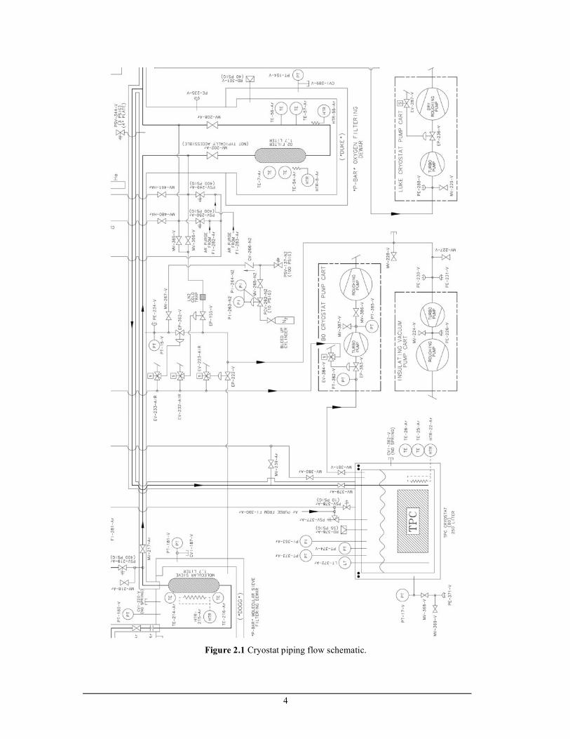
2.0 Flow schematic
The relevant portion of the flow schematic for the cryostat is shown in Figure 2.1.
The complete flow schematic is available at http://lartpc-docdb.fnal.gov:8080/cgi-
bin/ShowDocument?docid=265 in Section 1.2.
4
Figure 2.1 Cryostat piping flow schematic.

5
3.0 Design codes and evaluation criteria
The “Bo” LArTPC cryostat piping must meet all of the requirements of Section
5031.1 of the Fermilab ES&H Manual. This section states that piping systems containing
cryogenic fluids fall under the category of Normal Fluid Service and shall adhere to the
requirements of the ASME Process Piping Code B31.3.
4.0 Materials
The piping is fabricated from 304/304L stainless steel tube and pipe. In addition
to 304/304L material, some of the components and flanges are 316/316L stainless steel.
The lowest allowable stress for both of these materials from Table A-1 of ASME B31.3
will be used in this analysis, which is 16,700 psi. A portion of the existing piping that
feeds the new construction is fabricated from copper tube for which Table A-1 lists 6,000
psi as the allowable stress.
The LAr piping will be operated at 87 K. This is above the minimum temperature
listed for 304/316 stainless steel pipe or tube (19 K). According to Table 323.2.2 of the
Code, impact testing is not required for these austenitic stainless steels. However, Table
323.2.2 does require impact testing of the weld metal and heat affected zone except as
stated in Table 323.2.2 Note (6) where impact testing is not required when the minimum
obtainable Charpy specimen has a width along the notch of less than 2.5 mm (0.098 in).
All of the pipe or tube used in the “Bo” cryostat piping system has a manufacturer’s
minimum wall thickness less than 0.098 in. Therefore, impact testing is not required for
this piping system. It should also be noted the Fermilab has extensive service experience
using the 300 series stainless steels at liquid nitrogen temperatures.
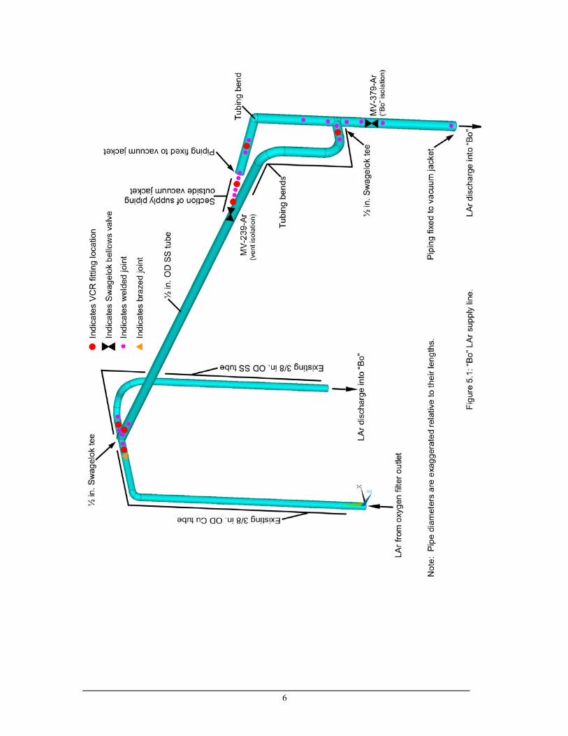
5.0 Piping design and analysis A schematic of the piping that supplies LAr to “Bo” is shown in Figure 5.1. The
cooldown/bypass vent piping associated with “Bo” is shown in Figure 5.2.
6

7

8
The minimum thickness of the pipes is evaluated using the procedures in
304.1.2(a) of ASME B31.3. The minimum tube thickness for seamless or longitudinally
welded piping for t<D/6 is given by:
)(2 PYSEW
PDt
+=
where: t = wall thickness, (manufacturers minimum value is used)
P = internal design pressure
D = outside diameter (manufacturers nominal value is used)
S = allowable stress from table A-1
E = quality factor from table A-1A or A-1B = 0.8 (worst case)
W = weld joint strength reduction factor = 1
Y = coefficient from Table 304.1.1 = 0.4
Table 5.1 summarizes the results of the wall thickness calculation.
Table 5.1. Cryogenic piping parameters
Pipe / Tube P (psid)
D (in)
S (psi)
E t req’d (in)
t mfg min (in)
MAWP (psid)
LAr supply line (vacuum jacketed)
400a 0.500 16,700 0.8 0.00740 0.0315 1772
“Bo” relief valve supply piping
35b 1.900 16,700 0.8 0.00249 0.0954 1397
“Bo” relief valve discharge piping
< 1c 3 16,700 0.8 0.0001 0.0585 529
“Bo” cooldown/blowdown vent piping
<< 350d
0.500 16,700 0.8 0.0065 0.0315 1772
(a) Pressure limited by trapped volume relief valve (PSV-250-Ar).
(b) Pressure limited by cryostat ASME relief valve (PSV-377-Ar).
(c) Relief valve calculations estimate vent pressure drop as less than 1 psi
(http://lartpc-docdb.fnal.gov:8080/cgi-bin/ShowDocument?docid=265, Section
4.1a).
(d) Supply LAr dewer reliefs are set at 350 psig. The pressure in the
cooldown/blowdown vent pipe during system cooldown (when the crysotat is
bypassed) will be much less than 350 psig because 98% of the flow resistance is
upstream of the vent pipe. The resistance coefficient for the supply piping up to

9
the cooldown/blowdown vent piping is 340.9 while the resistance coefficient for
the vent piping is only 4.3 (all piping converted to a common reference diameter).
In the above four cases the manufacturer’s minimum wall thickness of the piping
is greater than the minimum thickness required by ASME B31.3.
The “unlisted components” installed in the “Bo” cryostat piping system as defined
in B31.3 Section 304.7.2 are shown in Table 5.2.
Table 5.2. Unlisted piping components.
Component Source Pressure
rating [psi]
System Design
Pressure (psid)
Comment
Union Tee, socket weld, 316L S.S.
Swagelok, SS-8-TSW-3 6,600a 400 ----
Reducing Union, 316L S.S.
Swagelok, 316L-8TB7-
6-6 3,300a 400 ----
VCR gland Swagelok, SS-8-VCR-3 3,000a 400 304.7.2(a) Extensive
service experiencec
VCR gland Swagelok, SS-6-VCR-3 3,000a 400 304.7.2(a) Extensive
service experiencec
VCR body Swagelok, SS-8-VCR-4 3,000a 400 304.7.2(a) Extensive
service experiencec
Bellows Sealed Valve Swagelok, SS-8BG-V47 1,000 400 304.7.2(a) Extensive
service experiencec
Bellows Sealed Valve Swagelok, SS-8BG-TW 1,000 400 304.7.2(a) Extensive
service experiencec
Conflat flange, 2 ¾ in. Lesker vacuumb 35 304.7.2(a) Extensive service experiencec
(a) Swagelok literature states that the fitting pressure ratings are based on an allowable stress value of
20,000 psi in accordance with B31.3 (calculated at room temperature).
(b) During the pressure test of the TPC signal feed thru flange (section 3.5j of the system cryogenic
safety report - http://lartpc-docdb.fnal.gov:8080/cgi-bin/ShowDocument?docid=265), a 2 ¾ in.
conflat flange was part of the test setup. This test pressurized the 2 ¾ in. conflat to 400 psig
without leakage. Thus the conflat was proof tested to > 3x the maximum operating pressure it will
see per 304.7.2(c).
(c) These components have performed satisfactorily during several transfer of liquid argon to “Luke.”
10
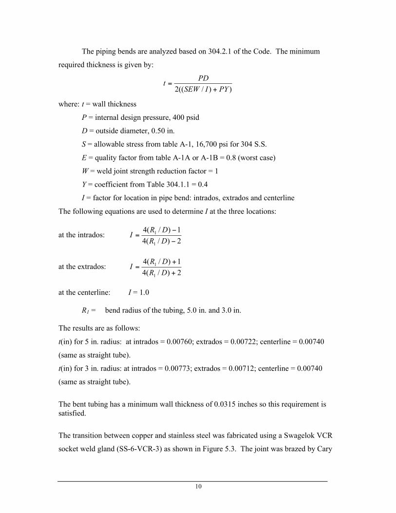
The piping bends are analyzed based on 304.2.1 of the Code. The minimum
required thickness is given by:
))/((2 PYISEW
PDt
+=
where: t = wall thickness
P = internal design pressure, 400 psid
D = outside diameter, 0.50 in.
S = allowable stress from table A-1, 16,700 psi for 304 S.S.
E = quality factor from table A-1A or A-1B = 0.8 (worst case)
W = weld joint strength reduction factor = 1
Y = coefficient from Table 304.1.1 = 0.4
I = factor for location in pipe bend: intrados, extrados and centerline
The following equations are used to determine I at the three locations:
at the intrados: 2)/(4
1)/(4
1
1
!
!=
DR
DRI
at the extrados: 2)/(4
1)/(4
1
1
+
+=
DR
DRI
at the centerline: I = 1.0 R1 = bend radius of the tubing, 5.0 in. and 3.0 in. The results are as follows:
t(in) for 5 in. radius: at intrados = 0.00760; extrados = 0.00722; centerline = 0.00740
(same as straight tube).
t(in) for 3 in. radius: at intrados = 0.00773; extrados = 0.00712; centerline = 0.00740
(same as straight tube).
The bent tubing has a minimum wall thickness of 0.0315 inches so this requirement is satisfied.
The transition between copper and stainless steel was fabricated using a Swagelok VCR
socket weld gland (SS-6-VCR-3) as shown in Figure 5.3. The joint was brazed by Cary

11
Kendziora using XUPER 1020 XFC silver brazing alloy which has a tensile strength of
85 ksi (data sheet included in the appendix). The gland mates to a Swagelock socket
weld tee to which 3 VCR fittings are welded. Before the brazed joint in the LAr transfer
line was fabricated, a test piece was brazed. This test piece was cold shocked in LN2,
passed a post cold shock helium mass spec leak check, and then split longitudinally to
investigate the quality of the brazing. The split test piece is also shown in Figure 5.3.
The flexibility of the LAr supply piping was analyzed using ANSYS. The model
boundary conditions and results are summarized in Figures 5.4 and 5.5.
Brazed joint
3/8 in. OD Cu tube
Flow to tee Flow from O2 filter
Figure 5.3: Brazed joint details
12
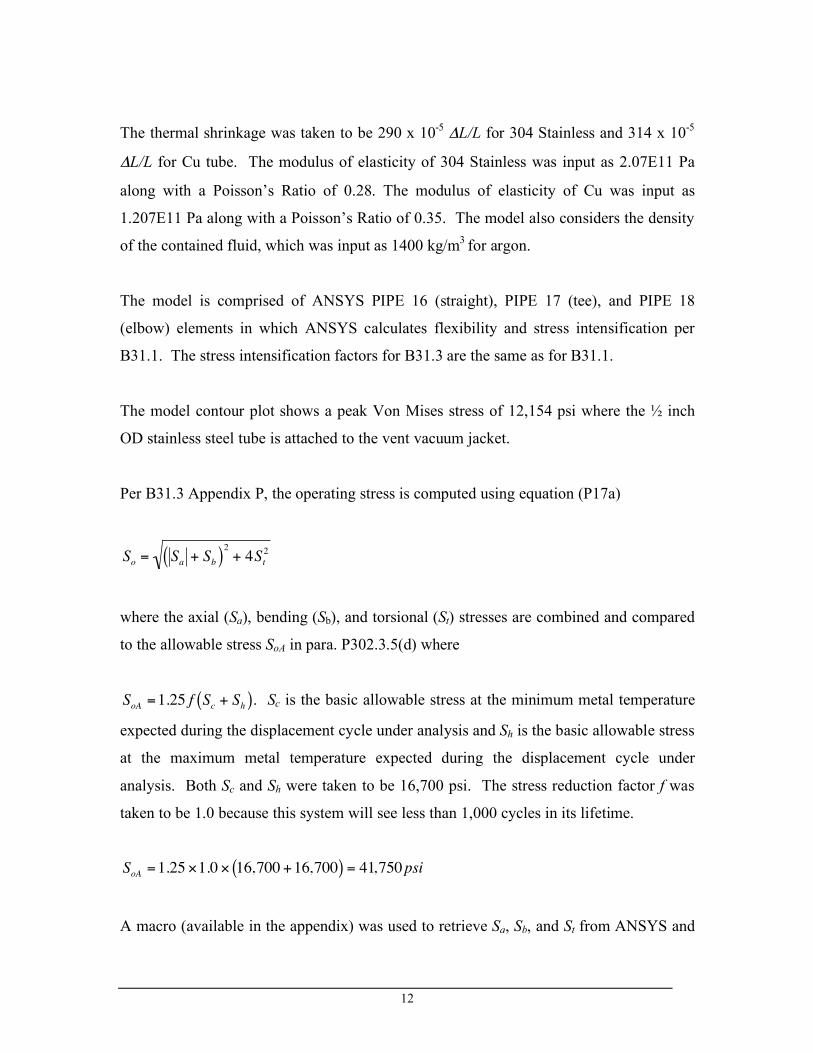
The thermal shrinkage was taken to be 290 x 10-5 ΔL/L for 304 Stainless and 314 x 10-5
ΔL/L for Cu tube. The modulus of elasticity of 304 Stainless was input as 2.07E11 Pa
along with a Poisson’s Ratio of 0.28. The modulus of elasticity of Cu was input as
1.207E11 Pa along with a Poisson’s Ratio of 0.35. The model also considers the density
of the contained fluid, which was input as 1400 kg/m3 for argon.
The model is comprised of ANSYS PIPE 16 (straight), PIPE 17 (tee), and PIPE 18
(elbow) elements in which ANSYS calculates flexibility and stress intensification per
B31.1. The stress intensification factors for B31.3 are the same as for B31.1.
The model contour plot shows a peak Von Mises stress of 12,154 psi where the ½ inch
OD stainless steel tube is attached to the vent vacuum jacket.
Per B31.3 Appendix P, the operating stress is computed using equation (P17a)
!
So
= Sa
+ Sb( )2
+ 4St
2
where the axial (Sa), bending (Sb), and torsional (St) stresses are combined and compared
to the allowable stress SoA in para. P302.3.5(d) where
!
SoA =1.25 f Sc + Sh( ). Sc is the basic allowable stress at the minimum metal temperature
expected during the displacement cycle under analysis and Sh is the basic allowable stress
at the maximum metal temperature expected during the displacement cycle under
analysis. Both Sc and Sh were taken to be 16,700 psi. The stress reduction factor f was
taken to be 1.0 because this system will see less than 1,000 cycles in its lifetime.
!
SoA =1.25 "1.0 " 16,700 +16,700( ) = 41,750psi
A macro (available in the appendix) was used to retrieve Sa, Sb, and St from ANSYS and

13
then compute the combined stress. The peak operating stress for this model was found to
be 6,032 psi for the cold case (thermal shrinkage + 400 psid) and 1,163 for the warm case
(400 psid loading only). Thus the operating stress range is only a few thousand psi and
does not exceed the allowable operating stress limit.
These stresses are below the 16,700 psi limit for the 304 SS tube or the 6,000 psi limit for
copper tube.
Figure 5.5 shows the results from a FEA model of the LAr vent piping that connects
“Bo” and “Luke” to the LAr vaporizer. The model considers the stress that results from
the shrinkage from 300 K to 80 K (no internal pressure). The material properties are the
same as those used in the LAr supply piping flexibility analysis.
The model shows a peak Von Mises stress of 3,582 psi where the ½ inch OD stainless
steel vent tube connects to Luke. Equation P17a computes a peak stress of 3,433 psi.
Thus the stress in the venting piping is far below the basic allowables for both the
stainless steel and copper piping.

14
Fixed to bottom of O2 filter
Liquid discharge fixed to piping vacuum jacket in Luke
Liquid discharge fixed to piping vacuum jacket in Bo
Fixed to vacuum jacket
3/8 in. OD Cu tube
3/8 in. OD SS tube
1/2 in. OD SS tube
Figure 5.4: LAr supply piping Von Mises Stresses due to cooldown shrinkage and internal 400 psid pressure.
(12,154 psi) (1,355 psi)
N/m2
LAr flow direction

15
Fixed to LAr vent piping vacuum jacket
Fixed to LAr vaporizer inlet
Figure 5.5: LAr vent piping Von Mises Stresses due to cooldown shrinkage.
(3,582 psi) (19 psi)
N/m2
Fixed to Bo top flange
Fixed to Luke top flange
1/2 in. OD SS tube
1 in. Type K Cu
Hanger fixes pipe in all directions except for Z
Hanger fixes pipe in all directions except for X
Z X
Y
16
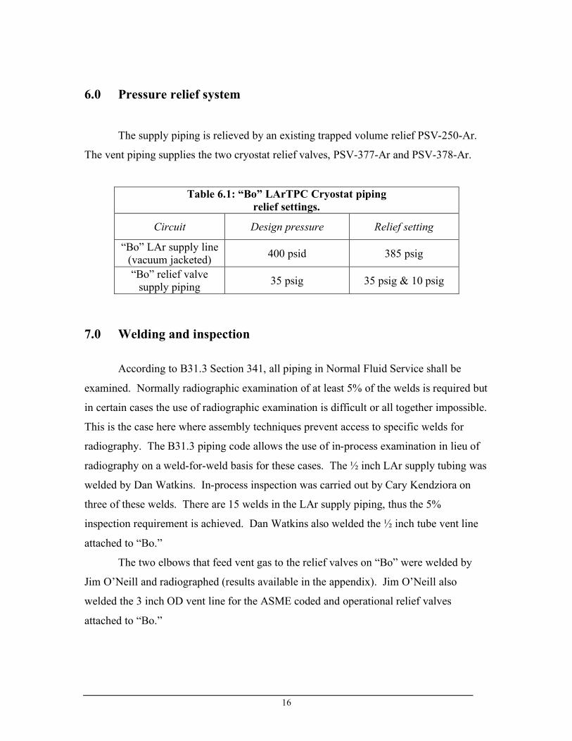
6.0 Pressure relief system
The supply piping is relieved by an existing trapped volume relief PSV-250-Ar.
The vent piping supplies the two cryostat relief valves, PSV-377-Ar and PSV-378-Ar.
Table 6.1: “Bo” LArTPC Cryostat piping relief settings.
Circuit Design pressure Relief setting
“Bo” LAr supply line (vacuum jacketed) 400 psid 385 psig
“Bo” relief valve supply piping 35 psig 35 psig & 10 psig
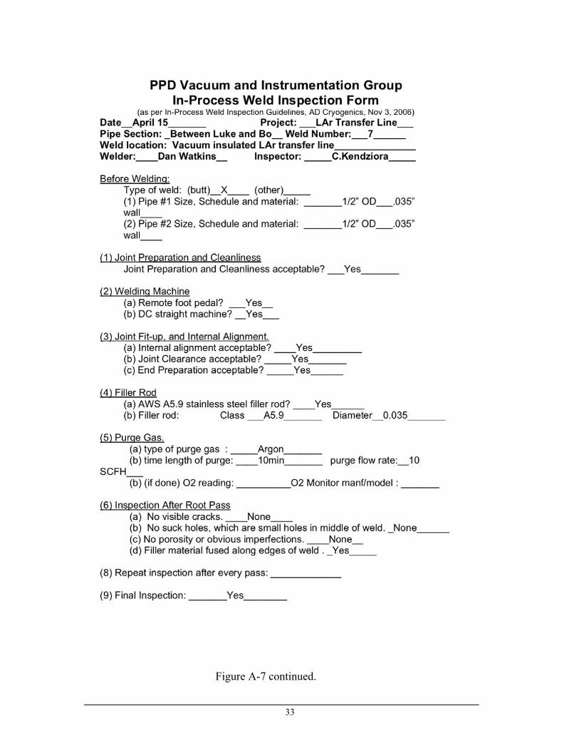
7.0 Welding and inspection According to B31.3 Section 341, all piping in Normal Fluid Service shall be
examined. Normally radiographic examination of at least 5% of the welds is required but
in certain cases the use of radiographic examination is difficult or all together impossible.
This is the case here where assembly techniques prevent access to specific welds for
radiography. The B31.3 piping code allows the use of in-process examination in lieu of
radiography on a weld-for-weld basis for these cases. The ½ inch LAr supply tubing was
welded by Dan Watkins. In-process inspection was carried out by Cary Kendziora on
three of these welds. There are 15 welds in the LAr supply piping, thus the 5%
inspection requirement is achieved. Dan Watkins also welded the ½ inch tube vent line
attached to “Bo.”
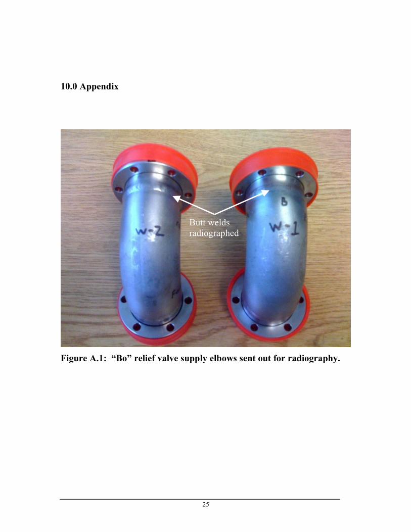
The two elbows that feed vent gas to the relief valves on “Bo” were welded by
Jim O’Neill and radiographed (results available in the appendix). Jim O’Neill also
welded the 3 inch OD vent line for the ASME coded and operational relief valves
attached to “Bo.”

17
8.0 Pressure testing
The piping system will be pressure tested in accordance with Section 5034 of the
Fermilab ES&H Manual and 345.5 of the Code. The test pressure is 110% of the design
pressure. The test pressures will be as follows:
• LAr supply circuit: 440 psig (while the vacuum jacket is evacuated and
monitored). • “Bo” cryostat: 40 psig (this tests the “Bo” relief valve supply piping and
the Category D piping up to the isolation points specified in the pressure
test documentation).
9.0 Category D piping The portion of piping that is associated with “Bo” and designed to operate at room
temperature and a maximum pressure of 35 psig is classified as Category D piping. This
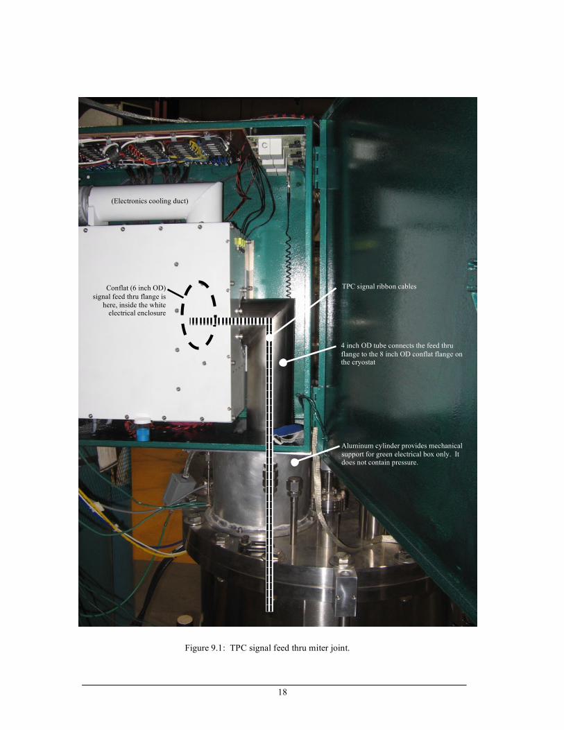
section describes these piping components. There is one miter joint in the system. It is shown in Figure 9.1.
18
Conflat (6 inch OD) signal feed thru flange is
here, inside the white electrical enclosure
4 inch OD tube connects the feed thru flange to the 8 inch OD conflat flange on the cryostat
Aluminum cylinder provides mechanical support for green electrical box only. It does not contain pressure.
TPC signal ribbon cables
Figure 9.1: TPC signal feed thru miter joint.
(Electronics cooling duct)

19
The strength of the miter joint is analyzed per 304.2.3(2)(4c):
!!
"
#
$$
%
&
'+'
''=
)()tan(25.1)(
)(
22 cTrcT
cT
r
cTSEWPm
(
S = 16,700 psi (Table A-1 for A 269 TP316L tube) E = 0.8 (lowest value listed for A 269 spec. stainless steel tube) W = 1.0 (per 302.3.5(e) for temperatures below 950 oF) T = 0.0585 in. (Nominal wall thickness of 0.065 in. minus manufacturer’s tolerance
of 10%) c = 0 (per 304.1.1(b) , the tubing has no thread or groove depth nor will corrosion
or erosionn occur) r2 = 1.9675 in. (mean radius of pipe using nominal wall
!
T , 2 – 0.065/2) θ = 45o (angle of miter cut)
!
Pm =16,700 " 0.8 "1.0(0.0585 # 0)
1.9675
0.0585 # 0
(0.0585 # 0) +1.25tan(45) 1.9675(0.0585 # 0)
$
% &
'
( ) = 48.1 psi
Thus the strength of the miter joint with respect to internal pressure is adequate
for the MAWP of “Bo.”
This section of piping will be evacuated such that it must be analyzed for external
pressure. Para. 304.2.4 states that the wall thickness of curved and mitered
segments of pipe subjected to external pressure maybe be determined as
specified for straight pipe in para. 304.1.3. Para. 304.1.3 states that UG-28 thru
UG-30 of the Section VIII Division 1 BPC code should be used to determine the
external pressure rating.
First Do / t is calculated where Do is the pipe outside diameter of 4.0 inches and t is the
wall thickness of 0.065 inches. Do / t = 4.0 / 0.065 = 61.5.

20
Because Do / t is greater than 4, calculate L / Do where L is the length of the cylinder
which is 11 inches. L / Do = 11 / 4.0 = 2.75. The length for the longest section of this
diameter piping is used.
Because L / Do is greater than 0.05 and less than 50, enter Figure G in ASME Section II
Part D and locate the value for Factor A. With a L / Do = 2.75 and Do / t = 61.5, Factor A
= 0.001.
From Figure HA-4 in Section II Part D, Factor B is 9,200 based on Factor A equal to
0.001 and the 100 oF modulus curve.
Because Do / t is greater than 10, the maximum allowable external pressure is calculated
using
!
P =4B
3Do
t
=4 " 9,200
34.0
0.065
=199psi.
The section of tubing that contains the mitered joint can handle the external pressure due to vacuum because 199 psi >> 15 psi. The welds in this section of piping have been visually examined per 341.4.2.
The purge flow to and from FI-390-Ar is supplied thru ¼ in. OD polyurethane tubing
which is rated for use from vacuum to 265 psi (McMaster part #5648K416). The supply
of GAr to this section is limited to 35 psig by PSV-276-Ar.
The vacuum jacket that surrounds the “Bo” LAr supply line is comprised of 4 in. OD
316L tubing (0.065 inch wall thickness). This tubing is welded to “Marmon” flanges
which were fabricated from MB-359521 which is entitled “Main Injector Vacuum
System φ Quick Disconnect Flange.” Based on extensive, successful service experience,
the “Marmon” flanges are qualified for this vacuum service. The longest length (11 ft.)
of 4 in. OD tubing is analyzed with respect to external pressure.

21
First Do / t is calculated where Do is the pipe outside diameter of 4.0 inches and t is the
wall thickness of 0.065 inches. Do / t = 4.0 / 0.065 = 61.5.
Because Do / t is greater than 4, calculate L / Do where L is the length of the cylinder
which is 11 inches. L / Do = 11 x 12 / 4.0 = 33.
Because L / Do is greater than 0.05 and less than 50, enter Figure G in ASME Section II
Part D and locate the value for Factor A. With a L / Do = 33 and Do / t = 61.5, Factor A =
0.0003.
From Figure HA-4 in Section II Part D, Factor B is 4,100 based on Factor A equal to
0.0003 and the 100 oF modulus curve.
Because Do / t is greater than 10, the maximum allowable external pressure is calculated
using
!
P =4B
3Do
t
=4 " 4,100
34.0
0.065
= 89psi.
Thus the longest section of vacuum jacket tubing (and any of the shorter similarly
constructed sections) can handle the external pressure due to vacuum because 89 psi >>
15 psi.
The instrumentation port that provides access to the insulating vacuum of “Bo” is
comprised of the components shown on the flow schematic and listed in the PI&D (such
as PT-17-V) and three pieces of piping. These pieces are a Swagelock VCR tee (vacuum
to 10,000 psig rating), a VCR to KF 25 adaptor (rated for vacuum), and a KF 25 cross
(rated for vacuum).
The piping that connects the commercial turbo vacuum pump cart to the cryostat has a total length of 6
inches and consists of two 3 inch long sections of piping. The first section adapts from a 4 ½ inch OD

22
conflat vacuum flange to a 6 inch OD conflat vacuum flange and these two flanges are joined by a SS
304L 2.5 inch OD tube with a 0.065 inch wall. A longer section of 2.5 inch OD tube with the 0.065 inch
wall is shown to be adequate for 15 psid external pressure in the document entitled “ASME Calculations
for the “Bo” cryostat top flange.” The second short section of vacuum piping consists of a 3 inch long 4
inch OD / 0.065 inch thick wall SS 316L tube with 6 inch OD conflat flanges on either end. This tubing
is qualified for the external pressure due to vacuum in the previous section that describes the vacuum
jacket.
PI-363-Ar is connected using a SS 304L 3/8 inch OD tube with a 0.035 inch wall thickness. Using the
equation in Section 5 of this document that relates wall thickness and pressure, this section of piping is
rated for 2400 psig internal pressure based on the manufacturers minimum wall thickness which far
exceeds the needed 35 psig rating. Its external pressure rating is calculated in the usual manner.
First Do / t is calculated where Do is the pipe outside diameter of 0.375 inches and t is the
wall thickness of 0.035 inches. Do / t = 0.375 / 0.035 = 10.7.
Because Do / t is greater than 4, calculate L / Do where L is the length of the cylinder
which is 12 inches. L / Do = 12 / 0.375 = 32.
Because L / Do is greater than 0.05 and less than 50, enter Figure G in ASME Section II
Part D and locate the value for Factor A. With a L / Do = 32 and Do / t = 10.7, Factor A =
0.011.
From Figure HA-3 in Section II Part D, Factor B is 15,000 based on Factor A equal to
0.011 and the 100 oF modulus curve.
Because Do / t is greater than 10, the maximum allowable external pressure is calculated
using
!
P =4B
3Do
t
=4 "15,000
30.375
0.035
=1,867psi.
23
Thus the section of tubing connecting the pressure gauge to the vapor space of “Bo” can
handle the external pressure due to vacuum because 1,867 psi >> 15 psi.
PT-373-Ar is connected to a Swagelock VCR male gland (pressure rating vacuum –
4,300 psig) that is welded to a 2 ¾ inch conflat flange.
RD-376-Ar is welded to a 1.5 inch OD / 0.065 inch wall SS 304L tube. Using the
equation in Section 5 of this document that relates wall thickness and pressure, this
section of piping is rated for 1,076 psig internal pressure based on the manufacturers
minimum wall thickness which far exceeds the needed 35 psig internal pressure rating.
Its external pressure rating is calculated in the usual manner.
First Do / t is calculated where Do is the pipe outside diameter of 1.500 inches and t is the
wall thickness of 0.065 inches. Do / t = 1.500 / 0.065 = 23.1.
Because Do / t is greater than 4, calculate L / Do where L is the length of the cylinder
which is 4.5 inches. L / Do = 4.5 / 1.500 = 3.
Because L / Do is greater than 0.05 and less than 50, enter Figure G in ASME Section II
Part D and locate the value for Factor A. With a L / Do = 3 and Do / t = 23.1, Factor A =
0.0036.
From Figure HA-3 in Section II Part D, Factor B is 11,000 based on Factor A equal to
0.0036 and the 100 oF modulus curve.
Because Do / t is greater than 10, the maximum allowable external pressure is calculated
using
24
!
P =4B
3Do
t
=4 "11,000
31.500
0.065
= 636psi.
Thus the section of tubing connecting the rupture disk can handle the external pressure
due to vacuum because 636 psi >> 15 psi.
PT-374-V is attached directly to a conflat flange.
25
10.0 Appendix
Figure A.1: “Bo” relief valve supply elbows sent out for radiography.
Butt welds radiographed
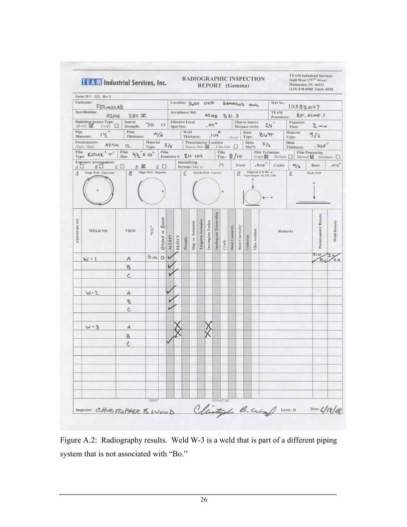
26
Figure A.2: Radiography results. Weld W-3 is a weld that is part of a different piping
system that is not associated with “Bo.”

27
Figure A-3: ANSYS macro used to compute operating stress.

28
Figure A-4: Dan Watkin’s welding qualification for stainless steel.
29
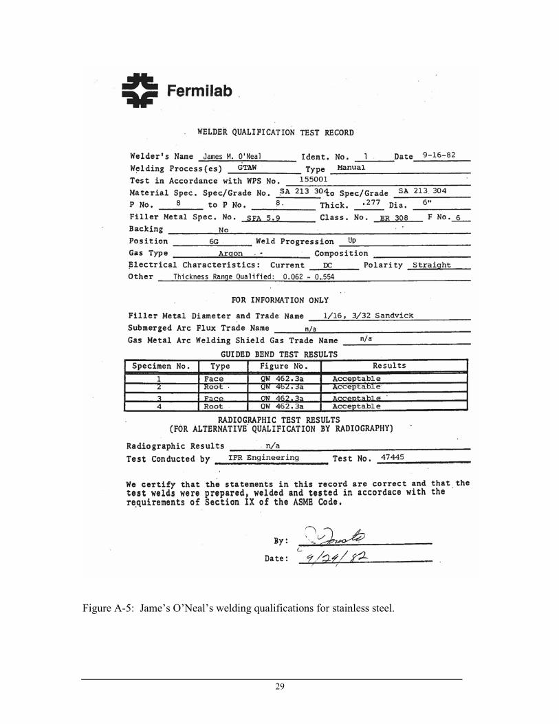
Figure A-5: Jame’s O’Neal’s welding qualifications for stainless steel.

30
Figure A-6: Brazing alloy used to join stainless steel and copper parts.

31
Figure A-6 continued.
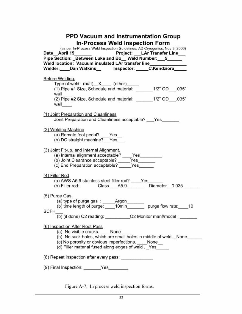
32
Figure A-7: In process weld inspection forms.
33
Figure A-7 continued.

34
Figure A-7 continued.