
BNB 130 300 Quick Start Guide
57
Alvarion BreezeNET ® B130/B300 Quick Start Guide Software Version: 1.2 November 2009 P/N 215477
-
Upload
vero-garcia-romero -
Category
Documents
-
view
176 -
download
5
Transcript of BNB 130 300 Quick Start Guide

Alvarion BreezeNET® B130/B300
Quick Start GuideSoftware Version: 1.2November 2009P/N 215477
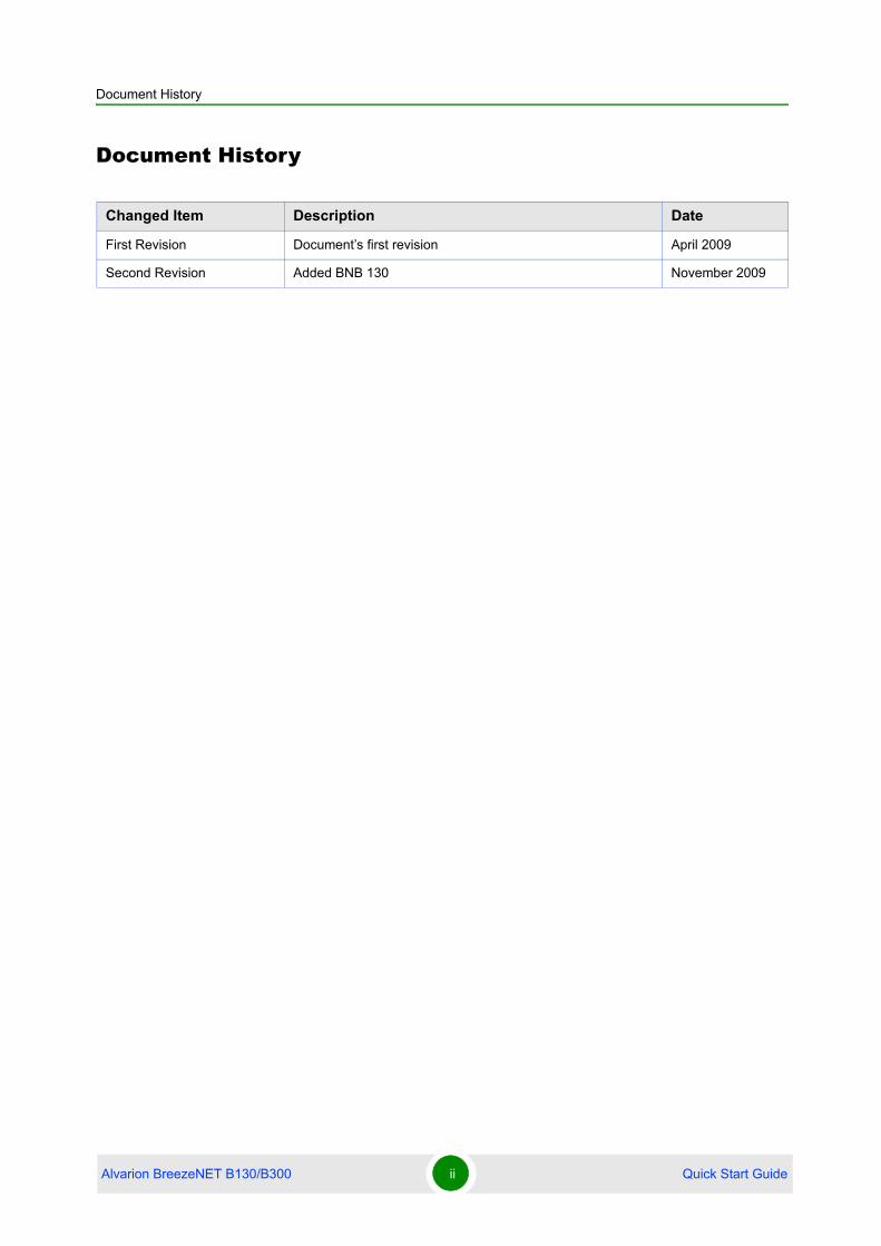
Document History
Document History
Changed Item Description Date
First Revision Document’s first revision April 2009
Second Revision Added BNB 130 November 2009
Alvarion BreezeNET B130/B300 ii Quick Start Guide

Legal Rights
Legal Rights© Copyright 2009 Alvarion Ltd. All rights reserved.
The material contained herein is proprietary, privileged, and confidential and
owned by Alvarion or its third party licensors. No disclosure thereof shall be made
to third parties without the express written permission of Alvarion Ltd.
Alvarion Ltd. reserves the right to alter the equipment specifications and
descriptions in this publication without prior notice. No part of this publication
shall be deemed to be part of any contract or warranty unless specifically
incorporated by reference into such contract or warranty.
Trade Names
Alvarion®, BreezeCOM®, WALKair®, WALKnet®, BreezeNET®, BreezeACCESS®,
BreezeMANAGE™, BreezeLINK®, BreezeConfig™, BreezeMAX™, AlvariSTAR™,
AlvariCRAFT™, BreezeLITE™, MGW™, eMGW™, 4Motion™, and/or other products
and/or services referenced here in are either registered trademarks, trademarks
or service marks of Alvarion Ltd.
All other names are or may be the trademarks of their respective owners.
Statement of ConditionsThe information contained in this manual is subject to change without notice.
Alvarion Ltd. shall not be liable for errors contained herein or for incidental or
consequential damages in connection with the furnishing, performance, or use of
this manual or equipment supplied with it.
Warranties and DisclaimersAll Alvarion Ltd. ("Alvarion") products purchased from Alvarion or through any of
Alvarion's authorized resellers are subject to the following warranty and product
liability terms and conditions.
Exclusive Warranty(a) Alvarion warrants that the Product hardware it supplies and the tangible
media on which any software is installed, under normal use and conditions, will
be free from significant defects in materials and workmanship for a period of
fourteen (14) months from the date of shipment of a given Product to Purchaser
(the "Warranty Period"). Alvarion will, at its sole option and as Purchaser's sole
remedy, repair or replace any defective Product in accordance with Alvarion'
standard R&R procedure.
(b) With respect to the Firmware, Alvarion warrants the correct functionality
according to the attached documentation, for a period of fourteen (14) month from
Alvarion BreezeNET B130/B300 iii Quick Start Guide

Legal Rights
invoice date (the "Warranty Period")". During the Warranty Period, Alvarion may
release to its Customers firmware updates, which include additional performance
improvements and/or bug fixes, upon availability (the "Warranty"). Bug fixes,
temporary patches and/or workarounds may be supplied as Firmware updates.
Additional hardware, if required, to install or use Firmware updates must be
purchased by the Customer. Alvarion will be obligated to support solely the two (2)
most recent Software major releases.
ALVARION SHALL NOT BE LIABLE UNDER THIS WARRANTY IF ITS TESTING
AND EXAMINATION DISCLOSE THAT THE ALLEGED DEFECT IN THE PRODUCT
DOES NOT EXIST OR WAS CAUSED BY PURCHASER'S OR ANY THIRD
PERSON'S MISUSE, NEGLIGENCE, IMPROPER INSTALLATION OR IMPROPER
TESTING, UNAUTHORIZED ATTEMPTS TO REPAIR, OR ANY OTHER CAUSE
BEYOND THE RANGE OF THE INTENDED USE, OR BY ACCIDENT, FIRE,
LIGHTNING OR OTHER HAZARD.
Disclaimer(a) The Software is sold on an "AS IS" basis. Alvarion, its affiliates or its licensors
MAKE NO WARRANTIES, WHATSOEVER, WHETHER EXPRESS OR IMPLIED,
WITH RESPECT TO THE SOFTWARE AND THE ACCOMPANYING
DOCUMENTATION. ALVARION SPECIFICALLY DISCLAIMS ALL IMPLIED
WARRANTIES OF MERCHANTABILITY AND FITNESS FOR A PARTICULAR
PURPOSE AND NON-INFRINGEMENT WITH RESPECT TO THE SOFTWARE.
UNITS OF PRODUCT (INCLUDING ALL THE SOFTWARE) DELIVERED TO
PURCHASER HEREUNDER ARE NOT FAULT-TOLERANT AND ARE NOT
DESIGNED, MANUFACTURED OR INTENDED FOR USE OR RESALE IN
APPLICATIONS WHERE THE FAILURE, MALFUNCTION OR INACCURACY OF
PRODUCTS CARRIES A RISK OF DEATH OR BODILY INJURY OR SEVERE
PHYSICAL OR ENVIRONMENTAL DAMAGE ("HIGH RISK ACTIVITIES"). HIGH
RISK ACTIVITIES MAY INCLUDE, BUT ARE NOT LIMITED TO, USE AS PART OF
ON-LINE CONTROL SYSTEMS IN HAZARDOUS ENVIRONMENTS REQUIRING
FAIL-SAFE PERFORMANCE, SUCH AS IN THE OPERATION OF NUCLEAR
FACILITIES, AIRCRAFT NAVIGATION OR COMMUNICATION SYSTEMS, AIR
TRAFFIC CONTROL, LIFE SUPPORT MACHINES, WEAPONS SYSTEMS OR
OTHER APPLICATIONS REPRESENTING A SIMILAR DEGREE OF POTENTIAL
HAZARD. ALVARION SPECIFICALLY DISCLAIMS ANY EXPRESS OR IMPLIED
WARRANTY OF FITNESS FOR HIGH RISK ACTIVITIES.
(b) PURCHASER'S SOLE REMEDY FOR BREACH OF THE EXPRESS
WARRANTIES ABOVE SHALL BE REPLACEMENT OR REFUND OF THE
PURCHASE PRICE AS SPECIFIED ABOVE, AT ALVARION'S OPTION. TO THE
FULLEST EXTENT ALLOWED BY LAW, THE WARRANTIES AND REMEDIES SET
FORTH IN THIS AGREEMENT ARE EXCLUSIVE AND IN LIEU OF ALL OTHER
Alvarion BreezeNET B130/B300 iv Quick Start Guide
Legal Rights
WARRANTIES OR CONDITIONS, EXPRESS OR IMPLIED, EITHER IN FACT OR BY
OPERATION OF LAW, STATUTORY OR OTHERWISE, INCLUDING BUT NOT
LIMITED TO WARRANTIES, TERMS OR CONDITIONS OF MERCHANTABILITY,
FITNESS FOR A PARTICULAR PURPOSE, SATISFACTORY QUALITY,
CORRESPONDENCE WITH DESCRIPTION, NON-INFRINGEMENT, AND
ACCURACY OF INFORMATION GENERATED. ALL OF WHICH ARE EXPRESSLY
DISCLAIMED. ALVARION' WARRANTIES HEREIN RUN ONLY TO PURCHASER,
AND ARE NOT EXTENDED TO ANY THIRD PARTIES. ALVARION NEITHER
ASSUMES NOR AUTHORIZES ANY OTHER PERSON TO ASSUME FOR IT ANY
OTHER LIABILITY IN CONNECTION WITH THE SALE, INSTALLATION,
MAINTENANCE OR USE OF ITS PRODUCTS.
Limitation of Liability(a) ALVARION SHALL NOT BE LIABLE TO THE PURCHASER OR TO ANY THIRD
PARTY, FOR ANY LOSS OF PROFITS, LOSS OF USE, INTERRUPTION OF
BUSINESS OR FOR ANY INDIRECT, SPECIAL, INCIDENTAL, PUNITIVE OR
CONSEQUENTIAL DAMAGES OF ANY KIND, WHETHER ARISING UNDER
BREACH OF CONTRACT, TORT (INCLUDING NEGLIGENCE), STRICT LIABILITY
OR OTHERWISE AND WHETHER BASED ON THIS AGREEMENT OR
OTHERWISE, EVEN IF ADVISED OF THE POSSIBILITY OF SUCH DAMAGES.
(b) TO THE EXTENT PERMITTED BY APPLICABLE LAW, IN NO EVENT SHALL
THE LIABILITY FOR DAMAGES HEREUNDER OF ALVARION OR ITS EMPLOYEES
OR AGENTS EXCEED THE PURCHASE PRICE PAID FOR THE PRODUCT BY
PURCHASER, NOR SHALL THE AGGREGATE LIABILITY FOR DAMAGES TO ALL
PARTIES REGARDING ANY PRODUCT EXCEED THE PURCHASE PRICE PAID
FOR THAT PRODUCT BY THAT PARTY (EXCEPT IN THE CASE OF A BREACH OF
A PARTY'S CONFIDENTIALITY OBLIGATIONS).
Disposal of Electronic and Electrical Waste
Disposal of Electronic and Electrical Waste
Pursuant to the WEEE EU Directive electronic and electrical waste must not be disposed of with unsorted waste. Please contact your local recycling authority for disposal of this product.
Alvarion BreezeNET B130/B300 v Quick Start Guide

Important Notice
Important NoticeThis user manual is delivered subject to the following conditions and restrictions:
This manual contains proprietary information belonging to Alvarion Ltd. Such
information is supplied solely for the purpose of assisting properly authorized
users of the respective Alvarion products.
No part of its contents may be used for any other purpose, disclosed to any
person or firm or reproduced by any means, electronic and mechanical,
without the express prior written permission of Alvarion Ltd.
The text and graphics are for the purpose of illustration and reference only.
The specifications on which they are based are subject to change without
notice.
The software described in this document is furnished under a license. The
software may be used or copied only in accordance with the terms of that
license.
Information in this document is subject to change without notice. Corporate
and individual names and data used in examples herein are fictitious unless
otherwise noted.
Alvarion Ltd. reserves the right to alter the equipment specifications and
descriptions in this publication without prior notice. No part of this
publication shall be deemed to be part of any contract or warranty unless
specifically incorporated by reference into such contract or warranty.
The information contained herein is merely descriptive in nature, and does not
constitute an offer for the sale of the product described herein.
Any changes or modifications of equipment, including opening of the
equipment not expressly approved by Alvarion Ltd. will void equipment
warranty and any repair thereafter shall be charged for. It could also void the
user's authority to operate the equipment.
Alvarion BreezeNET B130/B300 vi Quick Start Guide

Contents
Alvarion BreezeNET B130/B300 vii Quick Start Guide
Contents
Chapter 1 - Getting Started.....................................................................1
1.1 Scope of Document....................................................................................................3
1.2 Abbreviations .............................................................................................................4
1.3 Document Marks ........................................................................................................5
1.4 Additional Information ...............................................................................................6
Chapter 2 - Getting Access to the Unit...................................................7
2.1 PC/Laptop/LAN Connection ......................................................................................9
2.1.1 Cabling (Lab).......................................................................................................9
2.1.2 Accessing the Unit via Console.........................................................................11
2.1.3 Accessing the Unit via Ethernet ........................................................................15
2.2 Initial Setup ...............................................................................................................20
2.2.1 System Parameters...........................................................................................20
2.2.2 Learning Unit's Capabilities...............................................................................21
2.2.3 Radio Module Parameters Configuration ..........................................................22
Chapter 3 - Point-to-Point Configuration...............................................24
3.1 Unit’s Configuration.................................................................................................26
3.2 Learning Connection Status ...................................................................................28
3.3 Providing IP Connectivity........................................................................................30
3.3.1 Routed link ........................................................................................................30
3.3.2 Switched Link ....................................................................................................35
3.4 Link Throughput Test ..............................................................................................38
Chapter 4 - Performing Outdoor Testing...............................................40
4.1 Distance Setting .......................................................................................................42
4.2 Learning Link Status/Antenna Alignment Procedure ...........................................43
4.2.1 Antenna Alignment with MINT Monitor..............................................................44
4.2.2 Antenna alignment with Link test ......................................................................46
List of Figures
List of Figures
Figure 2-1: IDU Front ....................................................................................................................9
Figure 2-2: IDU Rear ................................................................................................................... 10
Figure 2-3: ODU Front.................................................................................................................10
Figure 2-4: Locating the HyperTerminal...................................................................................... 11
Figure 2-5: Selecting the Port .....................................................................................................12
Figure 2-6: Port Parameters........................................................................................................ 13
Figure 2-7: WANFleX OS Prompt ............................................................................................... 14
Figure 2-8: Changing the IP Address on eth0 Interface.............................................................. 15
Figure 2-9: Opening the Control Panel........................................................................................ 16
Figure 2-10: Network Connections.............................................................................................. 16
Figure 2-11: Connection Properties ............................................................................................17
Figure 2-12: Internet Protocol Properties .................................................................................... 17
Figure 2-13: Changing the IP Address........................................................................................ 18
Figure 2-14: Creating an Alias.....................................................................................................19
Figure 2-15: System Version.......................................................................................................21
Figure 2-16: Interfaces Information .............................................................................................22
Figure 2-17: Unit’s Capabilities ................................................................................................... 22
Figure 3-1: Sample Network (PtP Connection) ........................................................................... 25
Figure 3-2: “mint map” Command ............................................................................................... 28
Figure 3-3: Pinging Remote’s Ethernet ....................................................................................... 31
Figure 3-4: First Device...............................................................................................................33
Figure 3-5: Second Device.......................................................................................................... 34
Figure 3-6: First Device...............................................................................................................36
Figure 3-7: Second Device.......................................................................................................... 37
Figure 3-8: Load Meter Utility ......................................................................................................39
Figure 4-1: “mint monitor” output................................................................................................. 44
Figure 4-2: “muf stat” command output ....................................................................................... 45
Alvarion BreezeNET B130/B300 viii Quick Start Guide
List of Figures
Figure 4-3: “ltest” output .............................................................................................................. 47
Alvarion BreezeNET B130/B300 ix Quick Start Guide
1Chapter
Getting Started

Chapter 1 - Getting Started
In This Chapter:
“Scope of Document” on page 3
“Abbreviations” on page 4
“Document Marks” on page 5
“Additional Information” on page 6
This document is designed to help engineers/technicians in rapid configuring of
the system. The document includes detailed instructions for first configuration
steps and configuration scenarios for typical network topologies.
Alvarion BreezeNET B130/B300 2 Quick Start Guide

Chapter 1 - Getting Started Scope of Document
1.1 Scope of Document
This document consists of the following chapters:
“Getting Started” on page 1 - This chapter includes the information about this
document purpose and structure.
“Getting Access to the Unit” on page 7 - The chapter describes how to get
access to the device via Console Port and to configure Ethernet port.
“Point-to-Point Configuration” on page 24 - This chapter includes a
comprehensive list of instructions for point-to-point link configuration
including providing LAN connectivity.
“Performing Outdoor Testing” on page 40 - The chapter contains a list of
requirements for outdoor testing. Also some basic steps for link improvement
and antenna alignment are presented.
Alvarion BreezeNET B130/B300 3 Quick Start Guide

Chapter 1 - Getting Started Abbreviations
1.2 Abbreviations
The following abbreviations are used in this document:
ODU - Outdoor Unit
IDU - Indoor power supply Unit
RF cable - Radio Frequency cable to connect ODU and antenna
LOS - Line-of-Sight
STP cable - Shielded Twisted Pair cable to connect ODU and IDU. FTP (Foiled
Twisted Pair) CAT5e also can be used
PTP - Point-to-Point topology
MINT - Microwave Interconnection NeTworks
Alvarion BreezeNET B130/B300 4 Quick Start Guide

Chapter 1 - Getting Started Document Marks
1.3 Document Marks
CAUTION
All warnings are marked with a special warning sign. One should pay a great deal of attention to what is written in the Warning sections.
NOTE
All notes are marked with a special note sign. Notes usually contain useful comments or hints to the described section of the document.
Alvarion BreezeNET B130/B300 5 Quick Start Guide

Chapter 1 - Getting Started Additional Information
1.4 Additional Information
Additional information which is not included in this Manual can be found in the
following sources:
Device passport located in the box with the device
Technical User Manual
WANFleX OS User Guide
Alvarion BreezeNET B130/B300 6 Quick Start Guide

2Chapter
Getting Access to the Unit
Chapter 2 - Getting Access to the Unit
In This Chapter:
“PC/Laptop/LAN Connection” on page 9
“Initial Setup” on page 20
Alvarion BreezeNET B130/B300 8 Quick Start Guide

Chapter 2 - Getting Access to the Unit PC/Laptop/LAN Connection
2.1 PC/Laptop/LAN Connection
2.1.1 Cabling (Lab)The sequence of actions to be performed in order to connect the unit to the
PC/Laptop is the following:
1 Unpack the equipment
2 If you do not have a service cable soldered, please do it using special
connectors included into the package according to the soldering scheme
located in the "Supplementary information" section. STP cable cat 5 or cat 5E
should be used.
3 Locate IDU and ODU. Using STP Service cable connect ODU and IDU. Service
cable sockets are marked on the diagrams below
Figure 2-1: IDU Front
Alvarion BreezeNET B130/B300 9 Quick Start Guide

Chapter 2 - Getting Access to the Unit PC/Laptop/LAN Connection
Figure 2-2: IDU Rear
Figure 2-3: ODU Front
Alvarion BreezeNET B130/B300 10 Quick Start Guide
Chapter 2 - Getting Access to the Unit PC/Laptop/LAN Connection
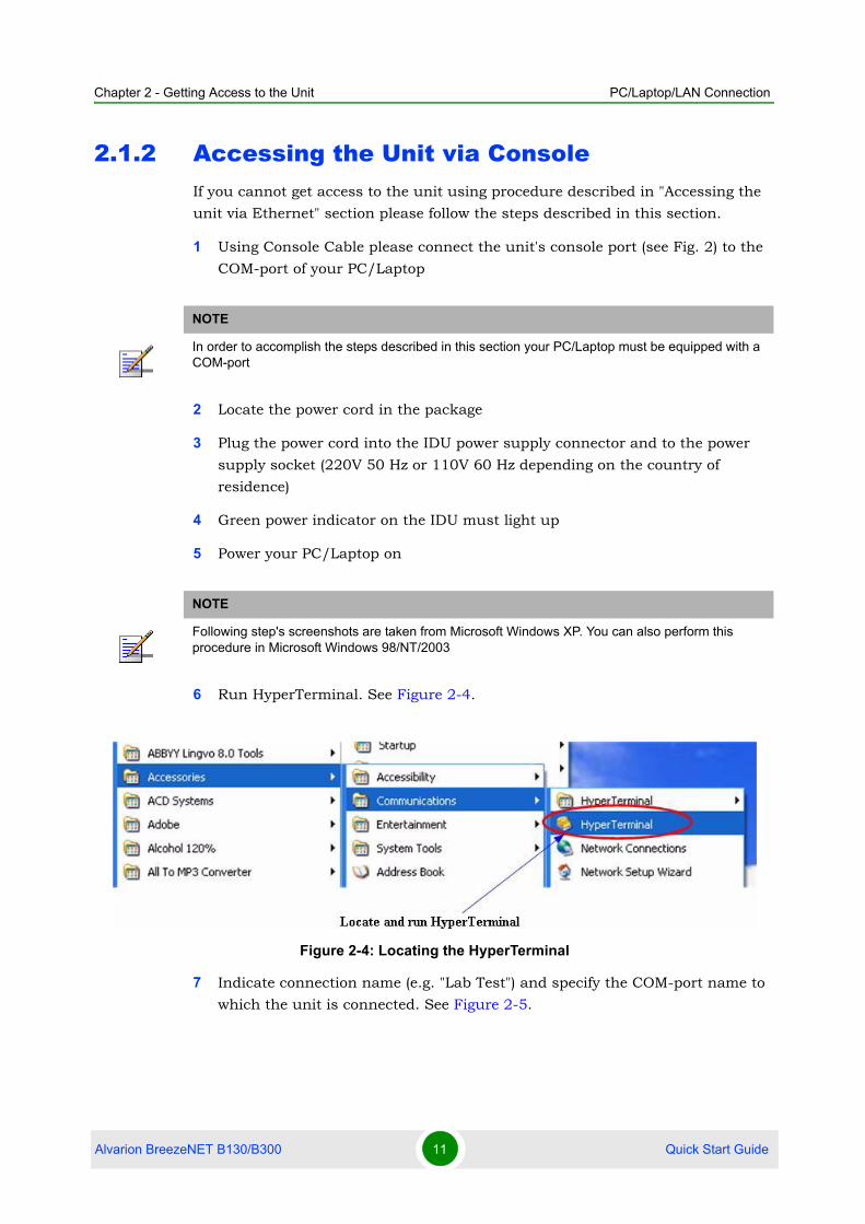
2.1.2 Accessing the Unit via ConsoleIf you cannot get access to the unit using procedure described in "Accessing the
unit via Ethernet" section please follow the steps described in this section.
1 Using Console Cable please connect the unit's console port (see Fig. 2) to the
COM-port of your PC/Laptop
2 Locate the power cord in the package
3 Plug the power cord into the IDU power supply connector and to the power
supply socket (220V 50 Hz or 110V 60 Hz depending on the country of
residence)
4 Green power indicator on the IDU must light up
5 Power your PC/Laptop on
6 Run HyperTerminal. See Figure 2-4.
7 Indicate connection name (e.g. "Lab Test") and specify the COM-port name to
which the unit is connected. See Figure 2-5.
NOTE
In order to accomplish the steps described in this section your PC/Laptop must be equipped with a COM-port
NOTE
Following step's screenshots are taken from Microsoft Windows XP. You can also perform this procedure in Microsoft Windows 98/NT/2003
Figure 2-4: Locating the HyperTerminal
Alvarion BreezeNET B130/B300 11 Quick Start Guide

Chapter 2 - Getting Access to the Unit PC/Laptop/LAN Connection
8 Specify port parameters exactly as shown on Figure 2-6.
Figure 2-5: Selecting the Port
Alvarion BreezeNET B130/B300 12 Quick Start Guide

Chapter 2 - Getting Access to the Unit PC/Laptop/LAN Connection
9 If you connected everything properly, selected the right port and made its
configuration right, after pressing enter on the white blank screen (after step
8) you should see WANFleX OS prompt as shown on Figure 2-7.
Figure 2-6: Port Parameters
Alvarion BreezeNET B130/B300 13 Quick Start Guide

Chapter 2 - Getting Access to the Unit PC/Laptop/LAN Connection
10 Your device has a factory configuration. The default login is "admin" and the
default password is "private".
11 Once this is done, you will see WANFleX CLI (Command Line Interface). See
Figure 2-8.
12 In order for your unit to be accessible from your LAN/PC/Laptop via Ethernet,
you should configure eth0 interface IP-address so the unit would allocate in
the desired LAN (or accessible from your PC/Laptop Ethernet adapter). Your
can change this IP-address via "ifc eth0" command as shown on figure 9. After
changing the IP-address, save the configuration using "co sa" command. In
the example given the IP-address being assigned to eth0 interface is 9.1.8.1
with mask length 24 (255.255.255.0). In order to check whether your changes
were correct, use "co sh ifc" command which shows configuration for all
interfaces of the unit. Do not forget to save your configuration using "co sa"
(config save) command.
Figure 2-7: WANFleX OS Prompt
Alvarion BreezeNET B130/B300 14 Quick Start Guide

Chapter 2 - Getting Access to the Unit PC/Laptop/LAN Connection
13 If all your settings are correct you can connect the unit to your LAN using UTP
cable with RJ-45 connectors (Ethernet port of the unit is located on IDU).
2.1.3 Accessing the Unit via EthernetIf your PC/Laptop does not have a COM-port or you want to plug the unit to the
LAN switch you can configure it using Telnet protocol.
The default IP-address assigned to the eth0 interface of the unit is 10.10.10.1
with 255.255.255.0 mask.
If you connect the unit directly to the LAN/PC/Laptop you should either change
the IP-address on the Ethernet adaptor or create an alias IP-address which would
be located in 10.10.10.0/24 network.
Connect the unit to LAN/PC/Laptop using UTP cable with RJ-45 connectors.
The procedure is the following:
1 Open the Control Panel in Windows. See Figure 2-9.
Figure 2-8: Changing the IP Address on eth0 Interface
Alvarion BreezeNET B130/B300 15 Quick Start Guide

Chapter 2 - Getting Access to the Unit PC/Laptop/LAN Connection
2 Open "Network connections" icon. See Figure 2-10.
3 In "Network connections" folder right mouse button click on the LAN
connection and click "Properties". See Figure 2-11.
Figure 2-9: Opening the Control Panel
Figure 2-10: Network Connections
Alvarion BreezeNET B130/B300 16 Quick Start Guide

Chapter 2 - Getting Access to the Unit PC/Laptop/LAN Connection
4 Choose "Internet protocol (TCP/IP)" and click "Properties". See Figure 2-12.
5 If you want to connect to the unit using PC/Laptop you can just change an
IP-address on the Ethernet adaptor to some address from 10.10.10.0/24
network (e.g. change "IP-address" field to "10.10.10.2" and "Subnet mask" to
"255.255.255.0"). After that click OK and move to step 7. See Figure 2-13.
Figure 2-11: Connection Properties
Figure 2-12: Internet Protocol Properties
Alvarion BreezeNET B130/B300 17 Quick Start Guide

Chapter 2 - Getting Access to the Unit PC/Laptop/LAN Connection
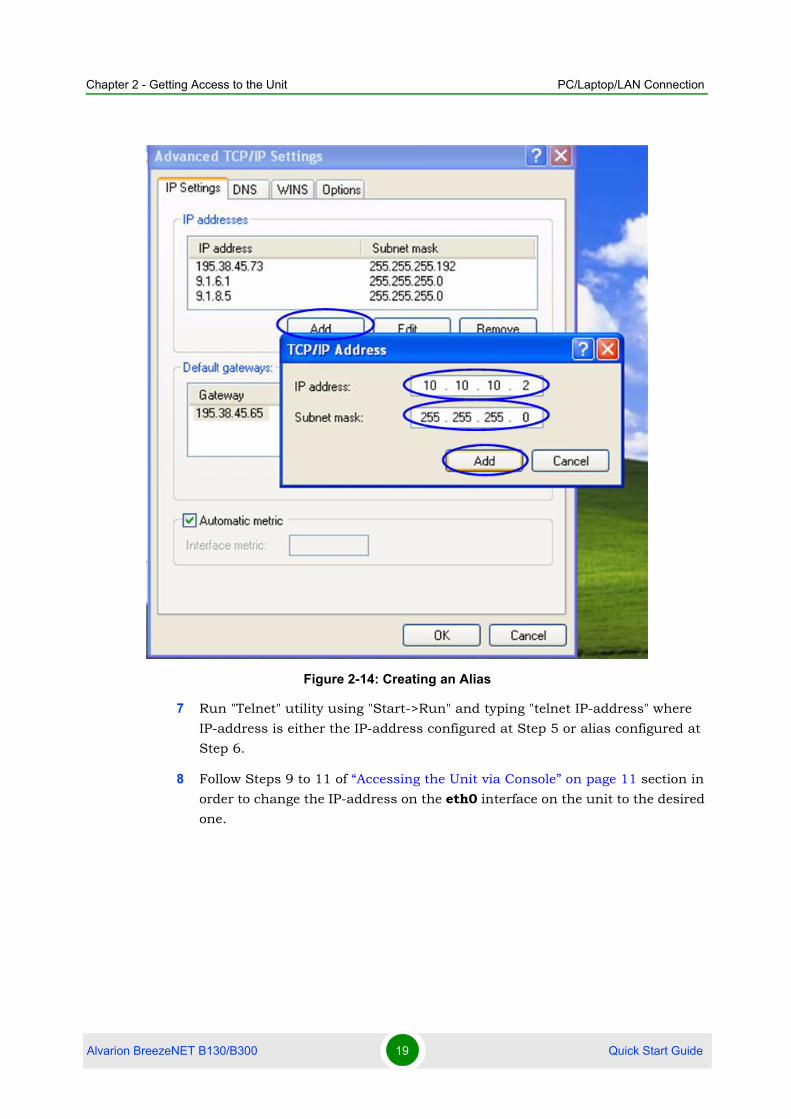
6 If you are in a LAN and you do not want to change your primary IP-address so
you could keep LAN connectivity, you can assign an alias. In order to do that,
press "Advanced…" button (Figure 14). In "Advanced TCP/IP Settings" click
"Add" and put alias IP-address and mask (e.g. "10.10.10.2" and
"255.255.255.0" correspondingly). See Figure 2-14. Click OK in all windows
opened in the described procedure.
Figure 2-13: Changing the IP Address
Alvarion BreezeNET B130/B300 18 Quick Start Guide
Chapter 2 - Getting Access to the Unit PC/Laptop/LAN Connection
7 Run "Telnet" utility using "Start->Run" and typing "telnet IP-address" where
IP-address is either the IP-address configured at Step 5 or alias configured at
Step 6.
8 Follow Steps 9 to 11 of “Accessing the Unit via Console” on page 11 section in
order to change the IP-address on the eth0 interface on the unit to the desired
one.
Figure 2-14: Creating an Alias
Alvarion BreezeNET B130/B300 19 Quick Start Guide

Chapter 2 - Getting Access to the Unit Initial Setup
2.2 Initial Setup
Once you have got the access to the unit via Telnet, you can perform initial unit
setup. Run telnet application (Start->Run) using IP-address that was assigned on
the eth0 interface of the unit (for example, 9.1.8.1)
First of all, let us list some useful commands that should be remembered.
"help" - lists all available commands in the unit
"config show" (or "co sh" for short) - shows unit's current configuration
"config save" (or "co sa" for short) - saves unit's current configuration
"restart y" - immediate unit reboot. Reboot lasts for 20-30 seconds
(approximately) and during this time you will not be able to control it over
Telnet. "restart XX" can be used for a postponed reboot so the unit will be
rebooted in XX seconds (this is very helpful when there is a risk of loosing a
remote unit while performing risky manipulations with configuration). "restart
0" cancels postponed reboot.
"quit" - closes current telnet session
2.2.1 System ParametersOnce you've got access to the unit, the most common thing to be done in the first
turn is to set up some basic system parameters:
System name. System name is specified by the following command:
system name [system_name]
System user. This parameter will be used as a login:
system user [user_name]
After specifying a user name you will need to type it the second time for
confirmation.
NOTE
The maximum number of concurrent Telnet sessions per one unit is five.
Alvarion BreezeNET B130/B300 20 Quick Start Guide

Chapter 2 - Getting Access to the Unit Initial Setup
System password. System password is used as a password while login:
system password [password]
After specifying a password you will need to type it the second time for
confirmation.
System prompt. This command will change current command line interface
prompt:
system prompt [any_word]
Also, it may be useful to know firmware version that is currently available in the
unit and unit's serial number. "Sys ver" command can be used for this purpose
(Figure 16):
2.2.2 Learning Unit's Capabilities1 In order to learn current interfaces configuration, execute "co sh ifc"
command.
2 In order to learn all configured interfaces, their states and statistics, execute
"ifc -a" command. See Figure 2-16.
Figure 2-15: System Version
Alvarion BreezeNET B130/B300 21 Quick Start Guide

Chapter 2 - Getting Access to the Unit Initial Setup
Information on the specific interface can be obtained using "ifc <IF-NAME>"
command. For example, "ifc rf5.0" will give you information on "rf5.0"
interface.
3 In order to get unit's capabilities including available frequency list, transmit
power levels, bitrates for the specific radio interface, "rf <IF-NAME> cap"
command is used. For example, "rf rf5.0 cap". See Figure 2-17.
2.2.3 Radio Module Parameters Configuration1 Power level changing is accomplished using "rf <IF-NAME> pwr
<power-level>" command. For example, "rf rf5.0 pwr 32" sets transmitting
power level to 32 mW. Power level specified in the command should be the one
from the list of available power levels.
Figure 2-16: Interfaces Information
Figure 2-17: Unit’s Capabilities
Alvarion BreezeNET B130/B300 22 Quick Start Guide

Chapter 2 - Getting Access to the Unit Initial Setup
2 Frequency changing is accomplished using "rf <IF-NAME> freq <frequency>"
command. For example, "rf rf5.0 freq 5340" sets current working frequency
to 5340 MHz.
3 Bitrate can be changed using "rf rf5.0 bitr <bitrate>" command. For example,
"rf rf5.0 bitr 130000" sets current bitrate to 130 Mbps.
Alvarion BreezeNET B130/B300 23 Quick Start Guide

3Chapter
Point-to-Point Configuration

Chapter 3 - Point-to-Point Configuration
In This Chapter:
“Unit’s Configuration” on page 26
“Learning Connection Status” on page 28
“Providing IP Connectivity” on page 30
“Link Throughput Test” on page 38
In our point-to-point configuration example we will built a simple network as
shown in Figure 3-1.
Here we will set up a connection between two PC/Laptops.
Figure 3-1: Sample Network (PtP Connection)
NOTE
All configuration samples and notes will use IP-addresses and names as specified in Figure 3-1.
Alvarion BreezeNET B130/B300 25 Quick Start Guide

Chapter 3 - Point-to-Point Configuration Unit’s Configuration
3.1 Unit’s Configuration
1 Choose two units.
2 Provide connectivity from PC1 to Unit1 and PC2 to Unit2 following the
procedure described in "“Getting Access to the Unit” on page 7". As a result
you should make sure that you can ping/telnet Unit1 from PC1 and
ping/telnet Unit 2 from PC2.
3 Now we will proceed to units configuration. From PC1 enter Unit 1 using
Telnet (Start->Run: "telnet 9.1.8.1") and from PC2 enter Unit 2 unit ("telnet
9.1.8.2").
4 Next step is configuring radio parameters of the radios. As the purpose of this
document is to show the basic settings we only will cover essential parameters
of the radio so that the connection could be established. In fact, radio has
many more other settings not mentioned below:
» Units should be configured for the same frequency. Example:
rf rf5.0 freq 5725
» Set up output power. For lab testing purposes the power can be configured
at the minimal value. Example:
rf rf5.0 pwr 4
» Units should have same SID. SID can be chosen as any 8-digit HEX
number. Example:
rf rf5.0 sid 11223344
» Set up desired working bitrate. Example:
rf rf5.0 bitr 52000
Please note that the list of allowed bitrates can be viewed using "rf rf5.0
cap" command and may depend on the unit's modification and selected
channel width (these settings are not within the scope of this document).
5 After radio configurations are done, we need to run MINT protocol which is a
core of the unit's architecture. On both units the following command should
be executed:
mint rf5.0 start
Alvarion BreezeNET B130/B300 26 Quick Start Guide

Chapter 3 - Point-to-Point Configuration Unit’s Configuration
If radio settings are done properly and units can physically "hear" each other,
the units will exchange a series of service packets and establish a connection.
In order to check it, one should use a command "mint map".
Also, the following configurations may be made in our particular PTP scenario:
» Set up a name for a network node (from MINT standpoint). Example:
mint rf5.0 -name "Test_Node_1"
» Set up node id (nodes in "mint map" will sorted according to this
numerical parameter):
mint rf5.0 -nodeid 1234
In order to see current MINT protocol configuration, use "co show mint"
command.
Alvarion BreezeNET B130/B300 27 Quick Start Guide

Chapter 3 - Point-to-Point Configuration Learning Connection Status
3.2 Learning Connection Status
Once all configuration steps are correctly performed you should make sure that
the connection is established.
Please keep in mind that once MINT protocol is working on MAC-layer (2nd layer
of OSI) IP-connectivity needs to be configured after link connectivity is
established.
Actually, it makes no sense to connect antennas to the devices while lab testing
but still you need to make them "hear" each other. Also you may try inserting
some kind of steel paper-clip in the connector - this might help in signal
improvement.
In order to learn current connection status, "mint map" command should be
used.
Example of "mint map" command output:
What important information do we learn from "mint map" output:
1 Current unit's neighbor of the device
2 Input / Output signal levels. Here, the parameters are displayed in dB above
current noise thresholds which are defined by current bitrates (displayed on
Figure 3-2: “mint map” Command
Alvarion BreezeNET B130/B300 28 Quick Start Guide
Chapter 3 - Point-to-Point Configuration Learning Connection Status
the right from signal levels). What is a good signal level (for current bitrate)?
For lower bitrates (equal or less than 52 Mbps) signal levels higher than 12-14
dB can be considered acceptable. For higher bitrates it is recommended to
have higher signal levels (>20 dB) in order to have a stable connection on this
bitrate and less retries and errors
3 Type of node: master or slave. In order to create PTP link, one unit should be
"master" and another one "slave". In this case a non-collision polling protocol
can be enabled on the "master" unit.
Alvarion BreezeNET B130/B300 29 Quick Start Guide

Chapter 3 - Point-to-Point Configuration Providing IP Connectivity
3.3 Providing IP Connectivity
Once we have connected our two units in a Point-to-Point link, the next step is to
configure IP-connectivity.
Units can be configured in either router or switch mode or even in hybrid mode
combining router and switch functionality.
In this manual we will review two most simple cases of link configuration in router
and switch mode.
3.3.1 Routed linkIn the simplest case, the following should be done to create routed link:
1 Configure two units' eth0 and eth1 (physical Ethernet) interfaces to a different
network subnets. In our example the addresses for eth 0 are 8.1.1.2/24
(8.1.1.0/24 network) and 8.1.2.6/24 (8.1.2.0/24 network), for eth1:
1.0.11.5/24 (1.0.11.0/24 network) and 1.0.12.4/24 (1.0.12.0/24 network).
Command example:
ifc eth0 8.1.2.6/24
Please note that after executing this command you will loose the connection to
your current telnet session (as you have logged on using different IP-address)
and you will need to re-log to the unit and save the configuration with a new
IP-address ("co save" command saves the configuration).
2 Next step is to configure a subnet between two radio interfaces. In our example
we use 10.10.10.0/30 network. One unit's radio interface gets 10.10.10.1
address and another one gets 10.10.10.2 address. Example:
ifc rf5.0 10.10.10.1/30
3 After configuring IP-addresses you can ping the opposite side of the link using
addresses assigned to radio interfaces.
4 Next, we need to configure routing between our four subnets which are
8.1.1.0/24, 8.1.2.0/24, 1.0.11.0/24 and 1.0.12.0/24. One can use static or
dynamic routing (RIP or OSPF). You can, for example, just enable RIP protocol
on both units or use static routing.
To enable RIP protocol on each unit type the following commands:
Alvarion BreezeNET B130/B300 30 Quick Start Guide

Chapter 3 - Point-to-Point Configuration Providing IP Connectivity
#2> arip start
Then enter ARIP router configuration mode:
#2> arip
RIP> configure
RIP(config)# router
And involve all the unit's interfaces in routing:
RIP(config-router)# network eth0
RIP(config-router)# network eth1
RIP(config-router)# network rf5.0
To configure static routing:
On each unit, e.g. on the second unit, which has 8.1.2.6/24 address on eth0
(Ethernet) and 10.10.10.2/30 on the radio interface (rf5.0) the command will
look as follows:
route add 8.1.1.0/24 10.10.10.1
which will mean that the network 8.1.1.0/24 is accessible via 10.10.10.1
address.
At this point, you can reach (e.g. ping) remote's eth0 interface both from one
unit to another.
The next step is to make you Laptops/PC/LAN "see" each other.
Figure 3-3: Pinging Remote’s Ethernet
Alvarion BreezeNET B130/B300 31 Quick Start Guide
Chapter 3 - Point-to-Point Configuration Providing IP Connectivity
If you connect two PC/Laptops (for example, Windows-basic) two options are
available in this case:
1 Write a route to the corresponding Ethernet network at the opposite side of the
link. In order to do this, go "Start->Run" and run "cmd" - Command Line. At
the computer connected to the first unit you should write the following:
route add 8.1.2.0 mask 255.255.255.0 8.1.1.2
This means that when an IP-packet goes from the computer connected to your
first device to the computer at the second side, it will go to the first device
Ethernet interface. In the unit, according to the routing tables formed using
RIP protocol, the packet will be sent via radio to the second unit. After that,
second unit will look up in its routing tables and send the packet through its
Ethernet interface to the remote computer.
At the second computer you should perform similar actions. Go "Start->Run"
and run "cmd" command. Type the following:
route add 8.1.1.0 mask 255.255.255.0 8.1.2.6
Now we provided connectivity between two computers.
2 The second option is to specify a default gateway for the PC/Laptop which is
going to be an Ethernet interface of the connected unit. You can specify
default gateway parameter in the window shown on Figure 14. Please refer.
For the first side it will be 8.1.1.2, for the second - 8.1.2.6
In order to make sure that your PC/Laptops are connected, you can ping one side
from the other one. For example, from one PC/laptop (located at one side of the
link) we are pinging remote computer at the opposite side.
NOTE
All routes in Windows that are specified using route command have power until next reboot of the computer (special parameter "-p" should be used to make a route permanent). To see the routing table in Windows "route print" command should be used.
IMPORTANT
IP-packets originated from the unit itself (e.g. ping, telnet, FTP, SNMP) are assigned an IP-address (primary) of the interface through which they leave the unit. In order for all IP-packets have one defined IP source address the following command can be used:
sys OfficialAddress IPHere, "IP" is the Official Address of the unit should be specified which will act as a source IP address for all the packets originated from the unit.
Alvarion BreezeNET B130/B300 32 Quick Start Guide

Chapter 3 - Point-to-Point Configuration Providing IP Connectivity
3.3.1.1 Sample Point-to-Point router configuration
Figure 3-4: First Device
Alvarion BreezeNET B130/B300 33 Quick Start Guide
Chapter 3 - Point-to-Point Configuration Providing IP Connectivity
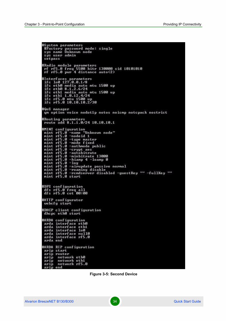
Figure 3-5: Second Device
Alvarion BreezeNET B130/B300 34 Quick Start Guide

Chapter 3 - Point-to-Point Configuration Providing IP Connectivity
3.3.2 Switched LinkMINT architecture has an ability of using switching capabilities. Switch, realized
in the units, is a very powerful tool that can be used in many different scenarios
but in this particular example we will be using it for one simple purpose - create a
simple switched link. The following steps should be taken:
1 Configure IP-addresses (e.g. on eth0 interface) from the same subnet. Say,
9.1.8.1/24 for the first unit and 9.1.8.2/24 for the second one.
2 On both units the switch needs to be configured. Although, switch realized in
the units is a powerful tool and can be used for many different purposes, here
in our example, we will use the simplest configuration which turns the unit to
a full switch mode. The following set of commands should be executed on both
units in the link:
switch group 1 add eth0 rf5.0
switch group 1 start
switch admin-group 1
switch start
Alvarion BreezeNET B130/B300 35 Quick Start Guide

Chapter 3 - Point-to-Point Configuration Providing IP Connectivity
3.3.2.1 Sample Point-to-Point Switch Configuration
Figure 3-6: First Device
Alvarion BreezeNET B130/B300 36 Quick Start Guide

Chapter 3 - Point-to-Point Configuration Providing IP Connectivity
Figure 3-7: Second Device
Alvarion BreezeNET B130/B300 37 Quick Start Guide

Chapter 3 - Point-to-Point Configuration Link Throughput Test
3.4 Link Throughput Test
The most evident way to test link throughput is to install FTP server on either first
or second computer.
During link throughput test using PC or Laptop with MS Windows please note the
following:
1 Hard disk drive speed or Ethernet adaptor speed may become a bottleneck of
the system at either side.
2 In MS Windows you need to run several (3 or more) TCP or UDP streams to
load up the radio link. In this case you will obtain a correct result.
Log on to FTP server on the remote computer. To do that go "Start->Run" and
execute "ftp 9.1.8.10". IP-address 9.1.8.10 is the address of the remote
computer. Enter login and password for the FTP-server.
Run several FTP streams from the remote computer. In order to do that create
several FTP sessions according to the procedure described in the previous
paragraph and start downloading files from the remote computer (files should be
relatively big).
Once the streams are run you can check the throughput using Load Meter utility
built into the unit. You can run it on either side. Run it for the eth0 interface. The
command is the following:
loadm -l rf5.0
"-l" parameter means line-by-line output.
The example is shown on the Figure 3-8.
Alvarion BreezeNET B130/B300 38 Quick Start Guide

Chapter 3 - Point-to-Point Configuration Link Throughput Test
Figure 3-8: Load Meter Utility
Alvarion BreezeNET B130/B300 39 Quick Start Guide
4Chapter
Performing Outdoor Testing

Chapter 4 - Performing Outdoor Testing
In This Chapter:
“Distance Setting” on page 42
“Learning Link Status/Antenna Alignment Procedure” on page 43
Before carrying out outdoor testing make sure that the equipment is properly
configured and tested in the lab. If you use outdoor equipment please prepare
service cables to connect IDU and ODU and check them in the lab. Also the
following accessories may be very useful while outdoor testing:
1 Console cable to perform configuration on the rooftops/masts, etc
2 Binoculars to locate the opposite side (within reasonable range)
3 Mobile phones at either side to coordinate each others actions
4 Screwdrivers set
5 Soldering iron in case if you have to fix some problems with connectors.
6 Voltage analyzer to reveal cable problems if any
When planning your outdoor testing it is strongly recommended to perform
calculations using:
Speed/Range Calculator
Fade Margin Calculator
How-to-use instructions are located in the Technical User Manual on the CD
delivered with the equipment.
Alvarion BreezeNET B130/B300 41 Quick Start Guide

Chapter 4 - Performing Outdoor Testing Distance Setting
4.1 Distance Setting
For outdoor testing/deployment it is vitally important to set up distance
parameter correctly. The recommended procedure is the following:
On one unit you set up the distance to the other unit in kilometers. It is required
to set up a bit bigger distance. Setting up a smaller distance may cause
errors on the link. At the other unit set up distance as auto or a bit bigger
distance than to the first unit
Distance parameter is set up using rf command:
rf rf5.0 distance <VALUE>
Alvarion BreezeNET B130/B300 42 Quick Start Guide

Chapter 4 - Performing Outdoor Testing Learning Link Status/Antenna Alignment Procedure
4.2 Learning Link Status/Antenna Alignment Procedure
In order to install the equipment, please do the following:
1 Install ODU and antenna at the roof top/mast etc. Connect ODU and antenna
using RF cable. If the link is just for testing usage make sure that it is not
going to rain or snow (because in this case you do not have to seal the
connectors).
2 Even in test link it is highly recommended to provide all grounding. Ground
the ODU to the mast/building grounding contour.
3 Usually when installing ODU at the top, the ODU-IDU service cable is already
connected to the ODU.
4 Connect ODU-IDU cable to IDU indoors.
5 Provide IDU grounding to the LAN grounding contour.
6 Connect power cable to IDU and plug this cable into the power socket.
Once the power is switched on, you can access the unit via Telnet (all necessary
configuration steps were already taken in the lab).
It will take several seconds for units to establish the connection. After this period
of time you can check the link status by using "mint map" command.
If it turns out that during some significant period of time (1 minute) there is no
link, several reasons may be the cause:
Link fade margin is not sufficient to handle the connection
Antenna alignment procedure is required in order to establish the connection
Units are not configured properly
Installation is made not according to the manual
Even if registration has occurred but signal levels are not enough antenna
alignment procedure is strongly recommended.
In both cases (whether there is a link or not) antenna alignment procedure is
recommended.
Alvarion BreezeNET B130/B300 43 Quick Start Guide

Chapter 4 - Performing Outdoor Testing Learning Link Status/Antenna Alignment Procedure
4.2.1 Antenna Alignment with MINT Monitor
1 On the unit run mint IFNAME monitor. Run it only from ONE side. The
command looks as follows (example):
mint rf5.0 monitor
Also, the following options of this command can be used:
"-s" option keeps the output on one screen
"-i SEC" option defines the periodicity of command's output (1 second by
default)
"MAC" option is a MAC-address (or several MAC-addresses) which should be
monitored (MAC-addresses can be viewed in "mint map" command)
2 Antenna alignment should be done only from one side at one time. Align one
side, than other side. Use mobile phones to check current signal levels. The
output of mint monitor command is demonstrated on the Figure 4-1.
3 The link can be claimed to be working when the following requirements are
met:
» Good signal levels. For low bitrates (<=52 Mbps) signal levels of 10-12 dB
and higher are appropriate. For higher bitrates (52 Mbps) signal levels of
higher than 18-20 dB should be achieved. For QAM64 bitrates (78 Mbps
NOTE
It is recommended to use "Antenna alignment with Link test" procedure instead of "Antenna alignment with MINT Monitor" procedure.
Figure 4-1: “mint monitor” output
Alvarion BreezeNET B130/B300 44 Quick Start Guide

Chapter 4 - Performing Outdoor Testing Learning Link Status/Antenna Alignment Procedure
and higher) signal levels of 30 dB and higher should be achieved for a
reliable link
» Low or zero repeats and errors. Please use "muf stat" command to see
statistics on errors. "muf stat clear" command clears the statistics.
» Link stability. Please check system log ("sys log show") if remote sides of
the link are permanently connected
Keep in mind that the antenna alignment should be performed slowly and with
pauses.
Also, important to remember that "mint monitor" command is a passive
command and does not generate any traffic. Thus, it is recommended to put
some load on the link while using "mint monitor"
4 Interference can be a possible reason for the link quality degradation (number
of repeats increases, lower signal levels due to higher noise levels or other
equipment working in the same area).
Figure 4-2: “muf stat” command output
Alvarion BreezeNET B130/B300 45 Quick Start Guide

Chapter 4 - Performing Outdoor Testing Learning Link Status/Antenna Alignment Procedure
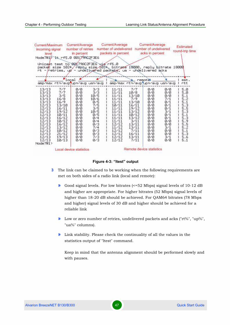
4.2.2 Antenna alignment with Link testIt is recommended to use "Antenna alignment with Link test" procedure instead of
"Antenna alignment with MINT Monitor" procedure because Link test is much
better radio link testing tool then Mint Monitor. This is so because of the following
reasons:
With Link test tool you are getting much more testing statistics using only one
command.
Link test tool perform "active testing", i.e. it generates special testing traffic
itself and then analyze radio link quality according to it. MINT Monitor doesn't
do that.
For Link test no MINT configuration needed.
Procedure:
1 On the unit run Link test. The command looks as follows:
ltest IFNAME MAC
Also, the following options of this command can be used:
"IFNAME" radio interface name which will be used in a test
"MAC" option is a MAC-address of the remote device on the opposite side of
the radio link
Example:
This command illustrates the simplest way to start link test. "lt" command
with all parameters undefined (default parameters) starts test of a local
device with a remote device which have "00179AC2F3E6" MAC-address.
2 Antenna alignment should be done only from one side at one time. Align one
side, than other side. Use mobile phones to check current signal levels. The
output of ltest command is demonstrated on the Figure 4-3.
lt rf5.0 00179AC2F3E6
Alvarion BreezeNET B130/B300 46 Quick Start Guide
Chapter 4 - Performing Outdoor Testing Learning Link Status/Antenna Alignment Procedure
3 The link can be claimed to be working when the following requirements are
met on both sides of a radio link (local and remote):
» Good signal levels. For low bitrates (<=52 Mbps) signal levels of 10-12 dB
and higher are appropriate. For higher bitrates (52 Mbps) signal levels of
higher than 18-20 dB should be achieved. For QAM64 bitrates (78 Mbps
and higher) signal levels of 30 dB and higher should be achieved for a
reliable link
» Low or zero number of retries, undelivered packets and acks ("rt%", "up%",
"ua%" columns).
» Link stability. Please check the continuality of all the values in the
statistics output of "ltest" command.
Keep in mind that the antenna alignment should be performed slowly and
with pauses.
Figure 4-3: “ltest” output
Alvarion BreezeNET B130/B300 47 Quick Start Guide

Chapter 4 - Performing Outdoor Testing Learning Link Status/Antenna Alignment Procedure
4 5.Interference can be a possible reason for the link quality degradation
(number of repeats increases, lower signal levels due to higher noise levels or
other equipment working in the same area).
Alvarion BreezeNET B130/B300 48 Quick Start Guide