BML - Airco Furnaces
32
BML (Lowboy Model) BMLV (Lowboy Model with ECM) Series B Oil Fired Warm Air Furnaces INSTALLATION, OPERATION & MAINTENANCE MANUAL P/N 30149, Rev. G [12/15/2016] ECR International 2210 Dwyer Avenue, Utica NY 13501 web site: www.ecrinternational.com
Transcript of BML - Airco Furnaces
BML (Lowboy Model)
BMLV (Lowboy Model with ECM)
Series BOil Fired Warm Air Furnaces
INSTALLATION, OPERATION & MAINTENANCE MANUAL
P/N 30149, Rev. G [12/15/2016]
ECR International 2210 Dwyer Avenue, Utica NY 13501
web site: www.ecrinternational.com

2 P/N 30149, Rev. G [12/15/2016]
Furnace Model
Cabinet Plenum Openings FlueFilter
(Permanent)Shipping Weight
(LB)WidthA
LengthB
HeightC
SupplyD x E
ReturnF x G Diameter Height
H
BMLBMLV
22" 51½" 32" 20½"x 19" 20½"x 18½" 5" 26¼" 20"x 20"x1" 240 LB
55.8 cm 130.8 cm 81.3 cm 52 cm x 49 cm 52.1 cm x 47 cm 12.7 cm 66.7 cm 51cm x 5cm x
2.6cm 108 Kg
Dimensions
F
G
1¾" (4.5cm)
E
H
B
C
D
A

3 P/N 30149, Rev. G [12/15/2016]
Check our website frequently for updates: www.ecrinternational.com
Information and specifications outlined in this manual in effect at thetime of printing of this manual. Manufacturer reserves the right to
discontinue, change specifications or system design at any time without notice and without incurring any obligation, whatsoever.
1. General ................................................................................................................................ 42. Safety Symbols ..................................................................................................................... 43. Introduction Models BML And BMLV .......................................................................................... 44. Heat Loss ............................................................................................................................. 45. Locating the Unit ................................................................................................................... 56. Furnace Used In Conjunction With Air Conditioning .................................................................... 57. Combustion Air ..................................................................................................................... 68. Chimney Venting ................................................................................................................... 69. Barometric Damper Control ..................................................................................................... 710. Optional Side Wall Venting ..................................................................................................... 711a. Fan Timer Board And Limit Control (BML) See Figure 3, page 15 ............................................... 711b. Fan Timer Board And Limit Control (BMLV) See Figure 4, page 15 ............................................. 712. Electrical Connections ........................................................................................................... 713. Humidifier ........................................................................................................................... 814. Piping Installation ................................................................................................................ 815. Oil Filter ............................................................................................................................. 816. Oil Burner Nozzles ............................................................................................................... 817. Oil Burner Adjustment .......................................................................................................... 818. Burner Electrodes ................................................................................................................ 819. Burner Primary (Safety) Control ............................................................................................. 920. Combustion Chamber ........................................................................................................... 921a. Circulating Air Blower (BML/BMLV) ........................................................................................ 921b. Circulating Air Blower (BMLV) .............................................................................................1022. Maintenance And Service .....................................................................................................1123. Operating Instructions (BML) ................................................................................................1224. Operating Instructions (BMLV) ..............................................................................................12Appendix A: Checkout and Adjustments ................................................................................. 13
A.1 Oil Burner Air Adjustment ..................................................................................................14A.2 Burner Electrodes .............................................................................................................15A.3 Start Up ..........................................................................................................................15A.4 Special Instructions For Units Equipped With Riello Burners .....................................................15A.5 Final Check Out ................................................................................................................16
Appendix B: Wiring Diagrams ................................................................................................ 20Chimney Vent Furnace Wiring Diagram BML/BMLV ......................................................................20Direct Vent Furnace Wiring Diagram BML/BMLV ..........................................................................21
Appendix C - Sequence of Operation and Troubleshooting ..................................................... 22C.1 Troubleshooting ................................................................................................................23C.2 Preliminary Steps ..............................................................................................................23C.3 Check Oil Primary Control ...................................................................................................23
Appendix D - Homeowner’s Reference Table .......................................................................... 27Parts Listing: Chimney Vent Models BML80(B2,BRF2) and BMLV80(B2,BRF2) ....................... 28Parts Listing: Direct Vent Models BML80(BB2U2,BRBU2) and BMLV80(BB2U2,BRBU2) .......... 30Parts Diagram BML and BMLV ................................................................................................ 31
4 P/N 30149, Rev. G [12/15/2016]
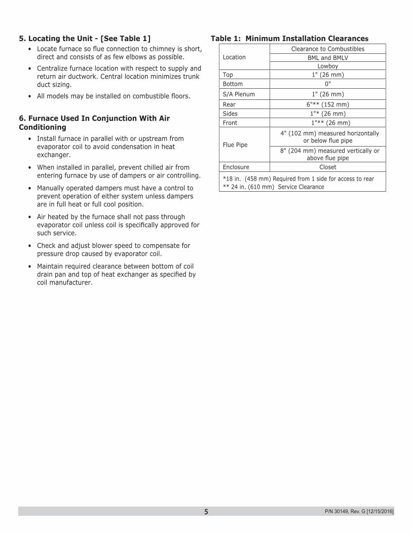
3. Introduction Models BML And BMLVModels BML and BMLV are oil fired forced air up-flow furnaces with an output capacity range of 59,000 btu/hr to 89,000 btu/hr.
• BML models are equipped with 1/2 HP PSC 4 speed blower motor.
• BMLV models are equipped with 1/2 HP ECM variable speed blower motor.
Furnace models are either factory equipped for chimney venting or factory equipped for direct venting. Chimney vent models and direct vent models are not field convertible. Direct vent installation instructions are included with the direct vent models.
Installation shall conform to requirements of authority having jurisdiction or in absence of such requirements:
• Canada - CAN/CSA - B139, Installation Code for Oil-Burning Equipment.
• United States - National Electrical Code, NFPA31, Standard for the Installation of Oil-Burning Equipment.
Models are CSA listed, (NRTL/C) for use with No. 1 (Stove) and No. 2 (Furnace) Oil. Refer to tables in Appendix A for performance data.
4. Heat LossMaximum hourly heat loss for each heated space shall be calculated in accordance with the procedures described in the manuals of:
• Canada - The Heating, Refrigeration and Air Conditioning Institute of Canada (HRAI), or by other means prescribed, or approved by the local authority having jurisdiction.
• United States - Manual J. titled, "Load Calculation" published by the Air Conditioning Contractors of America, describes a suitable procedure for calculating maximum hourly heat loss.
1. GeneralFurnace installation shall be completed by qualified agency. See glossary for additional information.
WARNINGFire, explosion, asphyxiation and electrical shock hazard. Improper installation could result in death or serious injury. Read this manual and understand all requirements before beginning installation.
!
NOTICEUsed to address practices not related to personal injury.
CAUTIONIndicates a hazardous situation which, if not avoided, could result in minor or moderate injury.
!
WARNINGIndicates a hazardous situation which, if not avoided, could result in death or serious injury.
!
DANGERIndicates a hazardous situation which, if not avoided, WILL result in death or serious injury
!
This is the safety alert symbol. Symbol alerts you to potential personal injury hazards. Obey all safety messages following this symbol to avoid possible injury or death.
Become familiar with symbols identifyingpotential hazards.
2. Safety Symbols
WARNINGFire, burn, asphyxiation hazard. Do not use gasoline, crank case oil, or any oil containing gasoline. Failure to follow these instructions could result in death or serious injury.
!
5 P/N 30149, Rev. G [12/15/2016]
5. Locating the Unit - [See Table 1]• Locate furnace so flue connection to chimney is short,
direct and consists of as few elbows as possible.
• Centralize furnace location with respect to supply and return air ductwork. Central location minimizes trunk duct sizing.
• All models may be installed on combustible floors.
6. Furnace Used In Conjunction With Air Conditioning
• Install furnace in parallel with or upstream from evaporator coil to avoid condensation in heat exchanger.
• When installed in parallel, prevent chilled air from entering furnace by use of dampers or air controlling.
• Manually operated dampers must have a control to prevent operation of either system unless dampers are in full heat or full cool position.
• Air heated by the furnace shall not pass through evaporator coil unless coil is specifically approved for such service.
• Check and adjust blower speed to compensate for pressure drop caused by evaporator coil.
• Maintain required clearance between bottom of coil drain pan and top of heat exchanger as specified by coil manufacturer.
Table 1: Minimum Installation Clearances
LocationClearance to Combustibles
BML and BMLVLowboy
Top 1" (26 mm)Bottom 0"
S/A Plenum 1" (26 mm)
Rear 6"** (152 mm)Sides 1"* (26 mm)Front 1"** (26 mm)
Flue Pipe
4" (102 mm) measured horizontally or below flue pipe
8" (204 mm) measured vertically or above flue pipe
Enclosure Closet
*18 in. (458 mm) Required from 1 side for access to rear** 24 in. (610 mm) Service Clearance
6 P/N 30149, Rev. G [12/15/2016]
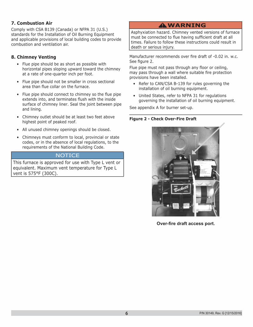
Manufacturer recommends over fire draft of -0.02 in. w.c. See figure 2.Flue pipe must not pass through any floor or ceiling, may pass through a wall where suitable fire protection provisions have been installed.
• Refer to CAN/CSA B-139 for rules governing the installation of oil burning equipment.
• United States, refer to NFPA 31 for regulations governing the installation of oil burning equipment.
See appendix A for burner set-up.
Over-fire draft access port.
7. Combustion AirComply with CSA B139 (Canada) or NFPA 31 (U.S.) standards for the Installation of Oil Burning Equipment and applicable provisions of local building codes to provide combustion and ventilation air.
8. Chimney Venting• Flue pipe should be as short as possible with
horizontal pipes sloping upward toward the chimney at a rate of one-quarter inch per foot.
• Flue pipe should not be smaller in cross sectional area than flue collar on the furnace.
• Flue pipe should connect to chimney so the flue pipe extends into, and terminates flush with the inside surface of chimney liner. Seal the joint between pipe and lining.
• Chimney outlet should be at least two feet above highest point of peaked roof.
• All unused chimney openings should be closed.
• Chimneys must conform to local, provincial or state codes, or in the absence of local regulations, to the requirements of the National Building Code.
NOTICEThis furnace is approved for use with Type L vent or equivalent. Maximum vent temperature for Type L vent is 575°F (300C).
WARNINGAsphyxiation hazard. Chimney vented versions of furnace must be connected to flue having sufficient draft at all times. Failure to follow these instructions could result in death or serious injury.
!
Figure 2 - Check Over-Fire Draft
7 P/N 30149, Rev. G [12/15/2016]
9. Barometric Damper ControlBarometric damper control, also known as draft regulator, is used on conventional chimney venting only. Control automatically maintains constant negative pressure. Ensures proper pressures are not exceeded. If chimney does not develop sufficient draft, draft control does not function properly.
• Install draft regulator in same room or enclosure as furnace. Draft regulator should not interfere with combustion air supplied to the burner.
• Locate control near furnace flue outlet. • Install per instructions supplied with regulator. • Set over fire draft, measured at oil burner mounting
plate over-fire draft access port, to -0.02 in. w.c. See Figure 2 page 6.
10. Optional Side Wall VentingCertain BML and BMLV furnace models are manufactured as sidewall vented units. Refer to Direct Venting Instructions, P/N 240006979 included with Vent Kit for details. Sidewall Venting (Direct Venting) requires use of specific oil burners; Beckett AFII, or Riello 40BF. Refer to Appendix A, Tables A2, and A4.
11a. Fan Timer Board And Limit Control (BML) See Figure 3, page 15.Electronic Fan Timer integrates control of burner and circulator fan operations. Control is central wiring point for most of furnace electrical components.
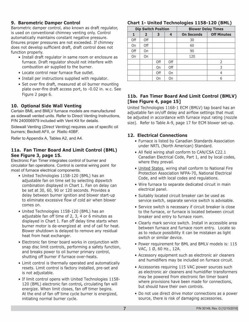
• United Technologies 1158-120 (BML) has an adjustable fan on time set by selecting dipswitch combination displayed in Chart 1. Fan on delay can be set at 30, 60, 90 or 120 seconds. Provides a delay between burner ignition and blower start-up to eliminate excessive flow of cold air when blower comes on.
• United Technologies 1158-120 (BML) has an adjustable fan off time of 2, 3, 4 or 6 minutes as displayed in Chart 1. Fan off delay time starts when burner motor is de-energized at end of call for heat. Blower shutdown is delayed to remove any residual heat from heat exchanger.
• Electronic fan timer board works in conjunction with snap disc limit controls, performing a safety function, and breaks power to oil burner primary control, shutting off burner if furnace over-heats.
• Limit control is thermally operated and automatically resets. Limit control is factory installed, pre-set and is not adjustable.
• If limit control opens with United Technologies 1158-120 (BML) electronic fan control, circulating fan will energize. When limit closes, fan off timer begins. At the end of fan off time cycle burner is energized, initiating normal burner cycle.
Chart 1- United Technologies 1158-120 (BML)Dip Switch Position Blower Delay Times
1 2 3 4 On Seconds Off MinutesOff Off 30On Off 60Off On 90On On 120
Off Off 2On Off 3Off On 4On On 6
11b. Fan Timer Board And Limit Control (BMLV) [See Figure 4, page 15]United Technologies 1168-1 ECM (BMLV) tap board has an adjustable fan on/off delay and airflow settings that must be adjusted in accordance with furnace input rating (nozzle size). Refer to Table A-9, page 17 for ECM blower set-up.
12. Electrical Connections• Furnace is listed by Canadian Standards Association
under NRTL (North American) Standard. • All field wiring shall conform to CAN/CSA C22.1
Canadian Electrical Code, Part 1, and by local codes, where they prevail.
• United States, wiring shall conform to National Fire Protection Association NFPA-70, National Electrical Code, and with local codes and regulations.
• Wire furnace to separate dedicated circuit in main electrical panel.
• Suitably located circuit breaker can be used as service switch, separate service switch is advisable.
• Service switch is necessary if circuit breaker is close to the furnace, or furnace is located between circuit breaker and entry to furnace room.
• Clearly mark service switch. Install in accessible area between furnace and furnace room entry. Locate so as to reduce possibility it can be mistaken as light switch or similar device.
• Power requirement for BML and BMLV models is: 115 VAC, 1 Ø, 60 Hz., 12A.
• Accessory equipment such as electronic air cleaners and humidifiers may be included on furnace circuit.
• Accessories requiring 115 VAC power sources such as electronic air cleaners and humidifier transformers may be powered from electronic fan timer board where provisions have been made for connections, but should have their own controls.
• Do not use direct drive motor connections as a power source, there is risk of damaging accessories.
8 P/N 30149, Rev. G [12/15/2016]
13. Humidifier• Humidifier is optional accessory available through
most heating supplies outlets. • Follow humidifier manufacturer's installation
instructions• Protect furnace heat exchanger from water or water
droplets from humidifier.• Do not use direct drive motor connections as source
of power for 115 VAC humidifiers and humidifier transformers.
14. Piping Installation• Install fuel system in accordance with requirements
of CAN/CSA B-139, and local regulations. • United States installation shall conform to NFPA No.
31 and local codes and authorities.• Use only approved fuel oil tanks, piping, fittings and
oil filter.• Install oil filter as close to burner as possible. • Refer to instructions and illustrations in oil burner and
oil pump instructions shipped with the furnace.
15. Oil FilterInstall oil filter between fuel oil storage tank and oil burner. When using oil burner nozzle smaller than 0.65 U.S. Gallons Per Hour, install additional 7 to 10 micron filter as close as possible to oil burner.
16. Oil Burner NozzlesBML and BMLV are certified for multiple firing rates, ranging from 59,000 to 89,000 Btu/h output. Furnace may be fired at ideal rate for wide range of structures by manipulating oil burner nozzle, flame retention head, and temperature rise. Refer to Table A-1 thru A-4, and furnace rating plate to determine proper combinations.
17. Oil Burner Adjustment• Adjust burner air supply to maintain fuel to air ratio
to obtain ideal combustion conditions.
• Lack of air causes "soft" and "sooty" flames, resulting in soot build-up throughout heat exchanger passages.
• Excess combustion air causes bright roaring fire and high stack temperatures resulting in poor fuel efficiency.
• BML and BMLV operate most efficiently with No. 1 smoke spot on Bacharach Scale. Dust will eventually build up on air moving components of oil burner assembly resulting in decreased air supply with potential soot build up in flue gas passageways of heat exchanger. Soot behaves as insulator and impairs good heat transfer. Stack temperature increases, and efficiency decreases. To avoid this problem, adjust the air supply to provide no more than trace smoke spot on Bacharach Scale.
• See Venting Instructions included in Vent Kits for set-up details for sidewall vented furnaces.
NOTICESet up sidewall vented models to deliver zero (0) smoke.
NOTICEBefore operating furnace check burner alignment with combustion chamber. End cone of air tube must be centred to accommodating ring of combustion chamber. Adjust as necessary.
18. Burner ElectrodesCorrect positioning of electrode tips with respect to each other, fuel oil nozzle, and burners is essential for smooth light ups and proper operation. Refer to oil burner instructions provided with furnace and Appendix A Section A.2 in this manual for electrode specifications.
• Thermostat wiring connections are shown in wiring diagrams in Appendix B. Some micro-electronic thermostats require additional controls and wiring. Refer to thermostat manufacturer's instructions.
• Locate thermostat approximately 5 feet above floor, on inside wall, and where thermostat is exposed to average room temperatures. Avoid locations where thermostat is exposed to cold drafts, heat from nearby lamps and appliances, exposure to sunlight, heat from inside wall stacks, etc.
• Adjust thermostat heat anticipator to amperage draw of heating control circuit as measured at "R" and "W" terminals of thermostat. Do not measure current with thermostat connected to the circuit. Measure amperage by connecting ammeter between two wires which connect to thermostat "R" and "W" terminals.
9 P/N 30149, Rev. G [12/15/2016]
19. Burner Primary (Safety) ControlFurnace is equipped with primary combustion control, also referred to as burner relay or burner protector relay, which uses a cad cell located in burner housing, to monitor and control combustion. Dust or combustion residuals can build up on lens of cad cell impairing its response to flame. Check cad cell for cleanliness and proper alignment if primary control fre-quently shuts down combustion.
20. Combustion ChamberFurnace is equipped with cerafelt combustion chamber, held in place by a retaining bracket.Check the alignment of the combustion chamber and oil burner before firing. It is possible for the combustion chamber to shift if subjected to rough handling during transit. Inspect combustion chamber for damage or carbon build up whenever oil burner is removed for repairs or routine maintenance.
WARNINGFire, burn, asphyxiation hazard. Do not start the burner unless blower access door is secured in place. Failure to follow these instructions could result in death or serious injury.
!
21a. CIRCULATING AIR BLOWER (BML/BMLV)• BML furnace models may be equipped with either
direct drive or belt drive blower systems.• BMLV furnace models are equipped with direct drive
blower systems. • BML models are equipped with PSC motors.• BMLV models are equipped with electronically
commutated motors (ECM).
Direct Drive Blower Systems• Direct drive blower speed adjustments are not
normally required in properly sized extended plenum duct systems. Motor RPM and air CFM delivery will vary automatically to accommodate conditions within usual range of external static pressures typical of residential duct systems.
• Under-sized duct systems may require higher blower speed to obtain system temperature rise.
• Some older duct systems were not designed to provide static pressure. They typically feature special reducing fittings at each branch run and lack block ends on the trunk ducts. These systems may require modification to provide some resistance to the airflow to prevent over-amping of direct drive blower motor. Selecting a lower blower speed may correct this problem.
• Direct drive blower speeds are adjusted by changing "hot" wires to motor winding connections. Refer to wiring diagrams in Appendix B or wiring diagram label affixed to furnace.
• Do not move neutral wire (normally white wire) to adjust blower speed.
• Single blower speed for both heating and cooling modes may be used. Use a "piggy-back connector" accommodating both wires on a single motor tap.
• It is also acceptable to connect selected motor speed with a pigtail joined to both heating and cooling speed wires with a wire nut.
• Safety precaution against accidental disconnection of wires by vibration, secure wire nut and wires with few wraps of electricians tape.
• Do not connect power leads between motor speeds. Always connect neutral wire to motor's designated neutral terminal.
• If joining blower speed wiring is done in furnace junction box, tape off both ends of unused wire.
• Do not use blower speed wires as source of power to accessories as electronic air cleaners and humidifier transformers. Unused motor taps auto-generate sufficiently high voltages to damage accessory equipment.
Belt Drive Blower Systems
WARNINGImproper installation could result in death or serious injury. Belt drive components operate at high speeds and may snag loose clothing resulting in injury or death. Have a trained service professional preform the following instructions. Failure to follow these instructions could result in death or serious injury.
!
Belt drive blower systems can be modified for speed and air delivery by adjusting variable speed motor pulley and changing blower pulley.
• Adjust variable speed motor pulley by loosening 5/32 allen set screw in outer sheave. Turn outer sheave clockwise to increase blower speed, counter clockwise to reduce speed.
NOTICEDo not tamper with furnace controls they are sensitive. If problems persist, call your service contractor.
10 P/N 30149, Rev. G [12/15/2016]
WARNINGElectrical shock hazard. Turn OFF electrical power supply at service panel before opening blower access door. Failure to do so could result in death or serious injury.
!
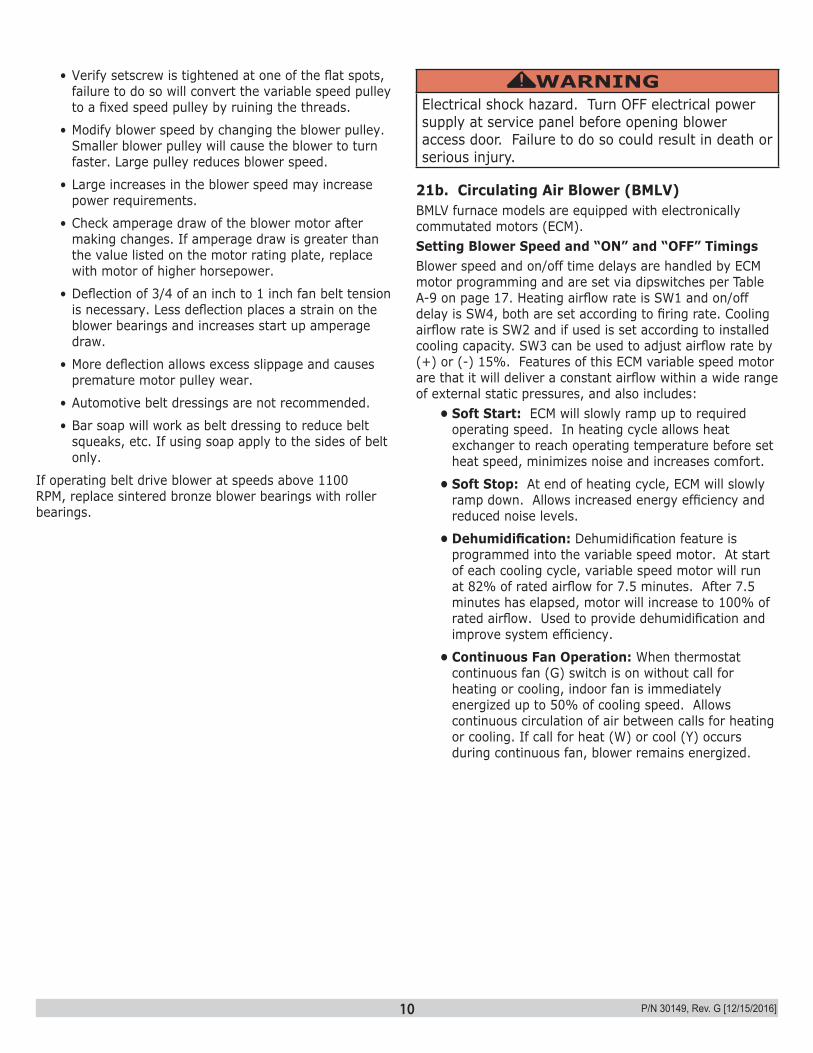
21b. Circulating Air Blower (BMLV) BMLV furnace models are equipped with electronically commutated motors (ECM). Setting Blower Speed and “ON” and “OFF” TimingsBlower speed and on/off time delays are handled by ECM motor programming and are set via dipswitches per Table A-9 on page 17. Heating airflow rate is SW1 and on/off delay is SW4, both are set according to firing rate. Cooling airflow rate is SW2 and if used is set according to installed cooling capacity. SW3 can be used to adjust airflow rate by (+) or (-) 15%. Features of this ECM variable speed motor are that it will deliver a constant airflow within a wide range of external static pressures, and also includes:
• Soft Start: ECM will slowly ramp up to required operating speed. In heating cycle allows heat exchanger to reach operating temperature before set heat speed, minimizes noise and increases comfort.
• Soft Stop: At end of heating cycle, ECM will slowly ramp down. Allows increased energy efficiency and reduced noise levels.
• Dehumidification: Dehumidification feature is programmed into the variable speed motor. At start of each cooling cycle, variable speed motor will run at 82% of rated airflow for 7.5 minutes. After 7.5 minutes has elapsed, motor will increase to 100% of rated airflow. Used to provide dehumidification and improve system efficiency.
• Continuous Fan Operation: When thermostat continuous fan (G) switch is on without call for heating or cooling, indoor fan is immediately energized up to 50% of cooling speed. Allows continuous circulation of air between calls for heating or cooling. If call for heat (W) or cool (Y) occurs during continuous fan, blower remains energized.
• Verify setscrew is tightened at one of the flat spots, failure to do so will convert the variable speed pulley to a fixed speed pulley by ruining the threads.
• Modify blower speed by changing the blower pulley. Smaller blower pulley will cause the blower to turn faster. Large pulley reduces blower speed.
• Large increases in the blower speed may increase power requirements.
• Check amperage draw of the blower motor after making changes. If amperage draw is greater than the value listed on the motor rating plate, replace with motor of higher horsepower.
• Deflection of 3/4 of an inch to 1 inch fan belt tension is necessary. Less deflection places a strain on the blower bearings and increases start up amperage draw.
• More deflection allows excess slippage and causes premature motor pulley wear.
• Automotive belt dressings are not recommended.
• Bar soap will work as belt dressing to reduce belt squeaks, etc. If using soap apply to the sides of belt only.
If operating belt drive blower at speeds above 1100 RPM, replace sintered bronze blower bearings with roller bearings.
11 P/N 30149, Rev. G [12/15/2016]
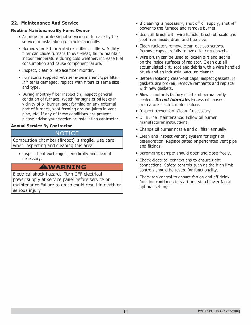
22. Maintenance And ServiceRoutine Maintenance By Home Owner
• Arrange for professional servicing of furnace by the service or installation contractor annually.
• Homeowner is to maintain air filter or filters. A dirty filter can cause furnace to over-heat, fail to maintain indoor temperature during cold weather, increase fuel consumption and cause component failure.
• Inspect, clean or replace filter monthly.
• Furnace is supplied with semi-permanent type filter. If filter is damaged, replace with filters of same size and type.
• During monthly filter inspection, inspect general condition of furnace. Watch for signs of oil leaks in vicinity of oil burner, soot forming on any external part of furnace, soot forming around joints in vent pipe, etc. If any of these conditions are present, please advise your service or installation contractor.
Annual Service By Contractor
NOTICECombustion chamber (firepot) is fragile. Use care when inspecting and cleaning this area
• Inspect heat exchanger periodically and clean if necessary.
WARNINGElectrical shock hazard. Turn OFF electrical power supply at service panel before service or maintenance Failure to do so could result in death or serious injury.
!
• If cleaning is necessary, shut off oil supply, shut off power to the furnace and remove burner.
• Use stiff brush with wire handle, brush off scale and soot from inside drum and flue pipe.
• Clean radiator, remove clean-out cap screws. Remove caps carefully to avoid tearing gaskets.
• Wire brush can be used to loosen dirt and debris on the inside surfaces of radiator. Clean out all accumulated dirt, soot and debris with a wire handled brush and an industrial vacuum cleaner.
• Before replacing clean-out caps, inspect gaskets. If gaskets are broken, remove remnants and replace with new gaskets.
• Blower motor is factory oiled and permanently sealed. Do not lubricate. Excess oil causes premature electric motor failure.
• Inspect blower fan. Clean if necessary.• Oil Burner Maintenance: Follow oil burner
manufacturer instructions.
• Change oil burner nozzle and oil filter annually.
• Clean and inspect venting system for signs of deterioration. Replace pitted or perforated vent pipe and fittings.
• Barometric damper should open and close freely.
• Check electrical connections to ensure tight connections. Safety controls such as the high limit controls should be tested for functionality.
• Check fan control to ensure fan on and off delay function continues to start and stop blower fan at optimal settings.
12 P/N 30149, Rev. G [12/15/2016]
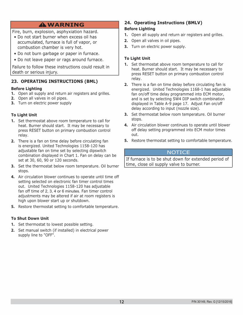
23. OPERATING INSTRUCTIONS (BML)Before Lighting1. Open all supply and return air registers and grilles.2. Open all valves in oil pipes.3. Turn on electric power supply
To Light Unit1. Set thermostat above room temperature to call for
heat. Burner should start. It may be necessary to press RESET button on primary combustion control relay.
2. There is a fan on time delay before circulating fan is energized. United Technologies 1158-120 has adjustable fan on time set by selecting dipswitch combination displayed in Chart 1. Fan on delay can be set at 30, 60, 90 or 120 seconds.
3. Set the thermostat below room temperature. Oil burner stops.
4. Air circulation blower continues to operate until time off setting selected on electronic fan timer control times out. United Technologies 1158-120 has adjustable fan off time of 2, 3, 4 or 6 minutes. Fan timer control adjustments may be altered if air at room registers is high upon blower start up or shutdown.
5. Restore thermostat setting to comfortable temperature.
To Shut Down Unit1. Set thermostat to lowest possible setting.2. Set manual switch (if installed) in electrical power
supply line to "OFF".
24. Operating Instructions (BMLV)Before Lighting1. Open all supply and return air registers and grilles.2. Open all valves in oil pipes.3. Turn on electric power supply.
To Light Unit1. Set thermostat above room temperature to call for
heat. Burner should start. It may be necessary to press RESET button on primary combustion control relay.
2. There is a fan on time delay before circulating fan is energized. United Technologies 1168-1 has adjustable fan on/off time delay programmed into ECM motor, and is set by selecting SW4 DIP switch combination displayed in Table A-9 page 17. Adjust Fan on/off delay according to input (nozzle size).
3. Set thermostat below room temperature. Oil burner stops.
4. Air circulation blower continues to operate until blower off delay setting programmed into ECM motor times out.
5. Restore thermostat setting to comfortable temperature.
NOTICEIf furnace is to be shut down for extended period of time, close oil supply valve to burner.
WARNINGFire, burn, explosion, asphyxiation hazard. • Do not start burner when excess oil has
accumulated, furnace is full of vapor, or combustion chamber is very hot.
• Do not burn garbage or paper in furnace. • Do not leave paper or rags around furnace.
Failure to follow these instructions could result in death or serious injury.
!
13 P/N 30149, Rev. G [12/15/2016]
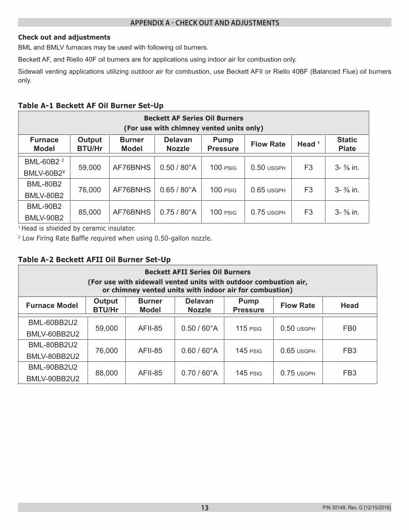
Check out and adjustmentsBML and BMLV furnaces may be used with following oil burners.
Beckett AF, and Riello 40F oil burners are for applications using indoor air for combustion only.
Sidewall venting applications utilizing outdoor air for combustion, use Beckett AFII or Riello 40BF (Balanced Flue) oil burners only.
Table A-1 Beckett AF Oil Burner Set-UpBeckett AF Series Oil Burners
(For use with chimney vented units only)
Furnace Model
Output BTU/Hr
Burner Model
Delavan Nozzle
Pump Pressure Flow Rate Head 1 Static
Plate
BML-60B2 2
BMLV-60B2²59,000 AF76BNHS 0.50 / 80°A 100 psig 0.50 usgph F3 3- ⅜ in.
BML-80B2BMLV-80B2
76,000 AF76BNHS 0.65 / 80°A 100 psig 0.65 usgph F3 3- ⅜ in.
BML-90B2BMLV-90B2
85,000 AF76BNHS 0.75 / 80°A 100 psig 0.75 usgph F3 3- ⅜ in.
1 Head is shielded by ceramic insulator. 2 Low Firing Rate Baffle required when using 0.50-gallon nozzle.
Table A-2 Beckett AFII Oil Burner Set-UpBeckett AFII Series Oil Burners
(For use with sidewall vented units with outdoor combustion air, or chimney vented units with indoor air for combustion)
Furnace Model Output BTU/Hr
Burner Model
Delavan Nozzle
Pump Pressure Flow Rate Head
BML-60BB2U2BMLV-60BB2U2
59,000 AFII-85 0.50 / 60°A 115 psig 0.50 usgph FB0
BML-80BB2U2BMLV-80BB2U2
76,000 AFII-85 0.60 / 60°A 145 psig 0.65 usgph FB3
BML-90BB2U2BMLV-90BB2U2
88,000 AFII-85 0.70 / 60°A 145 psig 0.75 usgph FB3
APPENDIX A - CHECK OUT AND ADJUSTMENTS

14 P/N 30149, Rev. G [12/15/2016]
Table A-3 Riello 40F Series Oil Burner Set-UpRiello 40F Series Oil Burners
(For use with chimney vented units)
Furnace Model Output BTU/Hr
Burner Model Delavan Nozzle Pump
Pressure Flow Rate Air Gate Turbulator Setting
BML-60BRF2BMLV-60BRF2
60,000 40F3 0.50 / 60°W 105 psig 0.50 usgph 2.6 1.0
BML-80BRF2BMLV-80BRF2
77,000 40F3 0.60 / 60°W 120 psig 0.65 usgph 2.6 1.5
BML-90BRF2BMLV-90BRF2
88,000 40F3 0.65 / 60°W 135 psig 0.75 usgph 3.6 2.0
Table A-4 Riello Balanced Flue (40BF) Burner Set-Up
Riello 40BF Balanced Flue Series Oil Burners(For use with sidewall vented units using outdoor combustion air)
Furnace Model Output BTU/Hr
Burner Model
Delavan Nozzle
Pump Pressure Flow Rate Turbulator
Setting
BML-60BRBU2BMLV-60BRBU2
61,000 40BF3 0.50 / 60°W 105 psig 0.50 usgph 1.0
BML-80BRBU2BMLV-80BRBU2
78,000 40BF3 0.60 / 60°W 120 psig 0.65 usgph 1.5
BML-90BRBU2BMLV-90BRBU2
89,000 40BF3 0.65 / 60°W 135 psig 0.75 usgph 2.0
NOTE: Air gate setting may vary for sidewall vented units where air gate must be adjusted to achieve zero smoke.
A.1 OIL BURNER AIR ADJUSTMENTConsult oil burner instructions provided in furnace documents envelope for specific information concerning burner adjustments, operation and troubleshooting.
Beckett AF Burner (Chimney Vent)Adjust air shutter by loosening locking screws. Moving air shutter, and if necessary, bulk air band.
Beckett AFII Burner (Direct Vent)Adjust burner air supply. Loosen locking screw located on black dial to right of burner. Turn black dial clockwise to increase combustion air and counter-clockwise to decrease combustion air. Re-tighten locking screw after obtaining proper setting.
Riello 40F3 Burner (Chimney Vent)Combustion air is adjusted by removing burner cover. Loosen screws that secure air adjustment plate. Move adjusting plate to either increase or decrease combustion air. When proper air setting is achieved, retighten fixing screws.
Riello 40BF3 Burner (Direct Vent)Combustion air can be adjusted with burner cover on. Remove plastic cover on top right hand side of burner cover. With phillips head screw driver, turn adjustment screw clockwise to increase combustion air or counter-clockwise to decrease combustion air. When combustion air is set, re-insert plastic cover.
APPENDIX A - CHECK OUT AND ADJUSTMENTS
15 P/N 30149, Rev. G [12/15/2016]
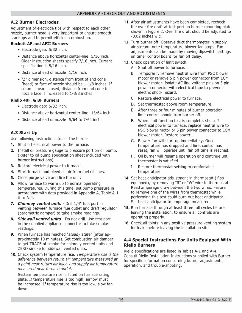
A.2 Burner ElectrodesAdjustment of electrode tips with respect to each other, nozzle, burner head is very important to ensure smooth start-ups and to permit efficient combustion.Beckett AF and AFII Burners
• Electrode gap: 5/32 inch.
• Distance above horizontal center-line: 5/16 inch. Older instruction sheets specify 7/16 inch. Current specification is 5/16 inch.
• Distance ahead of nozzle: 1/16 inch.
• “Z” dimension, distance from front of end cone (head) to face of nozzle should be 1-1/8 inches. If ceramic head is used, distance from end cone to nozzle face is increased to 1-3/8 inches.
Riello 40F, & BF Burners• Electrode gap: 5/32 inch.
• Distance above horizontal center-line: 13/64 inch.
• Distance ahead of nozzle: 5/64 to 7/64 inch.
A.3 Start UpUse following instructions to set the burner:1. Shut off electrical power to the furnace.2. Install oil pressure gauge to pressure port on oil pump.
(Refer to oil pump specification sheet included with burner instructions).
3. Restore electrical power to furnace.4. Start furnace and bleed all air from fuel oil lines.5. Close purge valve and fire the unit.6. Allow furnace to warm up to normal operating
temperatures. During this time, set pump pressure in accordance with data provided in Appendix A, Table A-1 thru A-4.
7. Chimney vented units - Drill 1/4" test port in venting between furnace flue outlet and draft regulator (barometric damper) to take smoke readings.
8. Sidewall vented units - Do not drill. Use test port in the supplied appliance connector to take smoke readings.
9. When furnace has reached "steady state" (after ap-proximately 10 minutes). Set combustion air damper to get TRACE of smoke for chimney vented units and ZERO smoke for sidewall vented units.
10. Check system temperature rise. Temperature rise is the difference between return air temperature measured at a point near return air inlet, and supply air temperature measured near furnace outlet. System temperature rise is listed on furnace rating plate. If temperature rise is too high, airflow must be increased. If temperature rise is too low, slow fan down.
11. After air adjustments have been completed, recheck the over fire draft at test port on burner mounting plate shown in Figure 2. Over fire draft should be adjusted to -0.02 inches w.c.
12. Turn burner off. Observe duct thermometer in supply air stream, note temperature blower fan stops. Fan adjustments can be made by moving dipswitch settings on timer control board for fan off delay.
13. Check operation of limit switch. A. Shut off power to furnace. B. Temporarily remove neutral wire from PSC blower
motor or remove 5 pin power connector from ECM blower motor. Isolate AC line voltage pins on 5 pin power connector with electrical tape to prevent electric shock hazard.
C. Restore electrical power to furnace. D. Set thermostat above room temperature. E. After three or four minutes of burner operation,
limit control should turn burner off. F. When limit function test is complete, shut off
electrical power to furnace, replace neutral wire to PSC blower motor or 5 pin power connector to ECM blower motor. Restore power.
G. Blower fan will start up immediately. Once temperature has dropped and limit control has reset, fan will operate until fan off time is reached.
H. Oil burner will resume operation and continue until thermostat is satisfied.
I. Restore thermostat setting to comfortable temperature.
14. Set heat anticipator adjustment in thermostat (if so equipped), by removing "R" or "W" wire to thermostat. Read amperage draw between the two wires. Failure to remove one of the wires from thermostat while performing this test could burn out heat anticipator. Set heat anticipator to amperage measured.
15. Run furnace through at least three full cycles before leaving the installation, to ensure all controls are operating properly.
16. Check all joints in any positive pressure venting system for leaks before leaving the installation site
A.4 Special Instructions For Units Equipped With Riello BurnersRiello specifications are listed in Tables A-1 and A-4. Consult Riello Installation Instructions supplied with Burner for specific information concerning burner adjustments, operation, and trouble-shooting.
APPENDIX A - CHECK OUT AND ADJUSTMENTS
16 P/N 30149, Rev. G [12/15/2016]
A.5 Final Check OutVerify all safety devices and electrical components have been set for normal operation. Verify all electrical connections are tight and wiring is secure.
Verify homeowner is informed and understands:Where circuit breaker or fuse is located in main electrical panel.Where furnace switch is located, and switch "on" and "off" positions if not obvious.
APPENDIX A - CHECK OUT AND ADJUSTMENTS
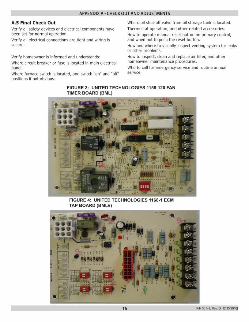
FIGURE 3: UNITED TECHNOLOGIES 1158-120 FAN TIMER BOARD (BML)
FIGURE 4: UNITED TECHNOLOGIES 1168-1 ECM TAP BOARD (BMLV)
Where oil shut-off valve from oil storage tank is located.Thermostat operation, and other related accessories.How to operate manual reset button on primary control, and when not to push the reset button.How and where to visually inspect venting system for leaks or other problems.How to inspect, clean and replace air filter, and other homeowner maintenance procedures.Who to call for emergency service and routine annual service.
17 P/N 30149, Rev. G [12/15/2016]
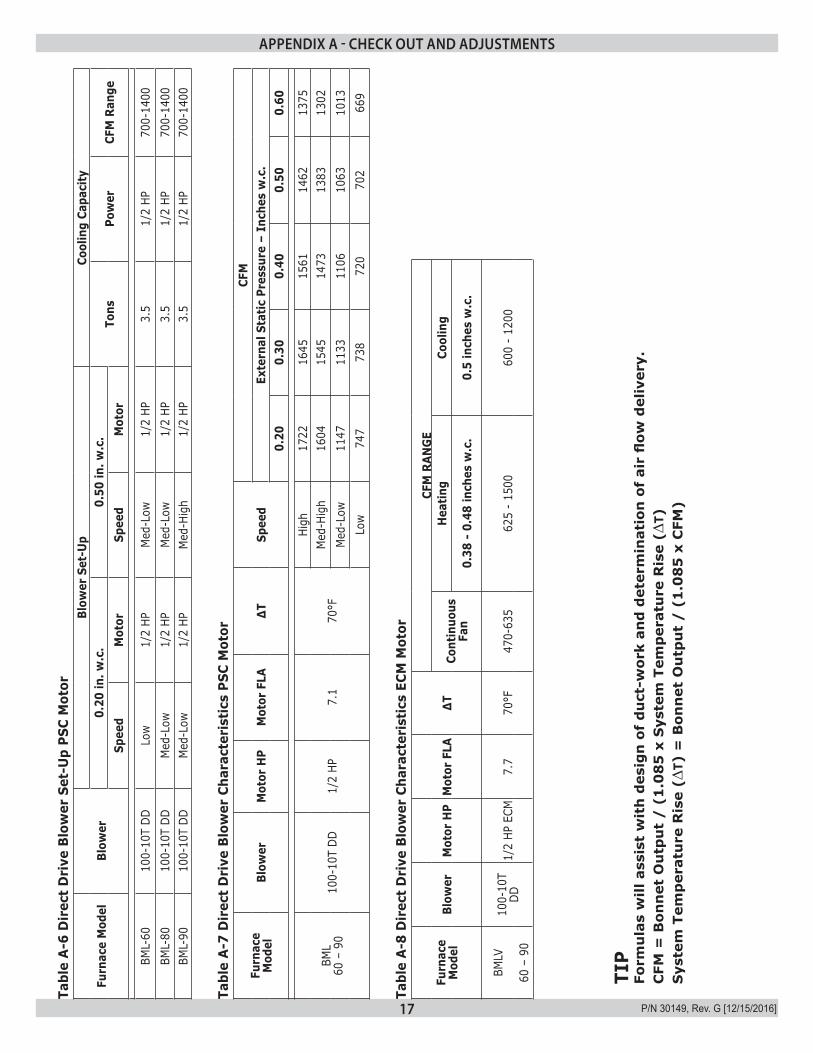
Tabl
e A
-6 D
irec
t D
rive
Blo
wer
Set
-Up
PSC
Mot
or
Furn
ace
Mod
elBl
ower
Blow
er S
et-U
pCo
olin
g Ca
paci
ty0.
20 in
. w.c
.0.
50 in
. w.c
.To
nsPo
wer
CFM
Ran
geSp
eed
Mot
orSp
eed
Mot
or
BML-
6010
0-10
T DD
Low
1/2
HPM
ed-L
ow1/
2 HP
3.5
1/2
HP70
0-14
00BM
L-80
100-
10T
DDM
ed-L
ow1/
2 HP
Med
-Low
1/2
HP3.
51/
2 HP
700-
1400
BML-
9010
0-10
T DD
Med
-Low
1/2
HPM
ed-H
igh
1/2
HP3.
51/
2 HP
700-
1400
Tabl
e A
-7 D
irec
t D
rive
Blo
wer
Cha
ract
eris
tics
PSC
Mot
or
Furn
ace
Mod
elBl
ower
Mot
or H
PM
otor
FLA
∆TSp
eed
CFM
Exte
rnal
Sta
tic P
ress
ure
– In
ches
w.c
.0.
200.
300.
400.
500.
60
BML
60 –
90
100-
10T
DD1/
2 HP
7.1
70°F
High
1722
1645
1561
1462
1375
Med
-Hig
h16
0415
4514
7313
8313
02M
ed-L
ow11
4711
3311
0610
6310
13Lo
w74
773
872
070
266
9
Tabl
e A
-8 D
irec
t D
rive
Blo
wer
Cha
ract
eris
tics
ECM
Mot
or
Furn
ace
Mod
elBl
ower
Mot
or H
PM
otor
FLA
∆TCF
M R
ANG
E
Cont
inuo
usFa
n
Hea
ting
Cool
ing
0.38
- 0
.48
inch
es w
.c.
0.5
inch
es w
.c.
BMLV
100-
10T
DD1/
2 HP
ECM
7.7
70°F
470-
635
625
- 15
0060
0 -
1200
60 –
90
APPENDIX A - CHECK OUT AND ADJUSTMENTS
TIP
Form
ula
s w
ill a
ssis
t w
ith
des
ign
of
du
ct-w
ork
and
det
erm
inat
ion
of
air
flow
del
iver
y.C
FM =
Bon
net
Ou
tpu
t /
(1
.08
5 x
Sys
tem
Tem
per
atu
re R
ise
(∆T)
Sys
tem
Tem
per
atu
re R
ise
(∆T)
= B
onn
et O
utp
ut
/ (
1.0
85
x C
FM)
18 P/N 30149, Rev. G [12/15/2016]
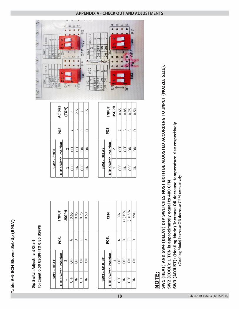
Tabl
e A
-9 E
CM B
low
er S
et-U
p (B
MLV
)
Dip
Sw
itch
Adju
stm
ent C
hart
For
Inpu
t 0.5
0 U
SGPH
TO
0.8
5 U
SGPH
SW1
- H
EAT
POS.
SW
2 -
COO
LPO
S.
DIP
Sw
itch
Posi
tion
INPU
TD
IP S
witc
h Po
sitio
nAC
Siz
e
12
USG
PH1
2(T
ON
)OF
FOF
FA
0.65
OFF
OFF
A3
ONOF
FB
0.85
ONOF
FB
2.5
OFF
ONC
0.75
OFF
ONC
2ON
OND
0.50
ONON
D1.
5
SW3
- AD
JUST
POS.
SW
4 -
DEL
AYPO
S.
DIP
Sw
itch
Posi
tion
CFM
DIP
Sw
itch
Posi
tion
INPU
T
12
1
2U
SGPH
OFF
OFF
A 0%
OFF
OFF
A0.
65ON
OFF
B (+
)15%
ONOF
FB
0.85
OFF
ONC
(-)1
5%OF
FON
C0.
75ON
OND
N/A
ONON
D0.
50
NO
TE:
SW1
(HEA
T) A
ND
SW
4 (D
ELA
Y) D
IP S
WIT
CHES
MU
ST B
OTH
BE
AD
JUST
ED A
CCO
RD
ING
TO
IN
PUT
(NO
ZZLE
SIZ
E).
SW2
(CO
OL)
: 1 T
ON
is a
ppro
xim
atel
y eq
ual t
o 40
0 CF
MSW
3 (A
DJU
ST):
(H
eati
ng M
ode)
Inc
reas
e O
R d
ecre
ase
tem
pera
ture
ris
e re
spec
tive
ly
(
Coo
ling
Mod
e) In
crea
se O
R d
ecre
ase
CFM
resp
ectiv
ely
APPENDIX A - CHECK OUT AND ADJUSTMENTS
19 P/N 30149, Rev. G [12/15/2016]
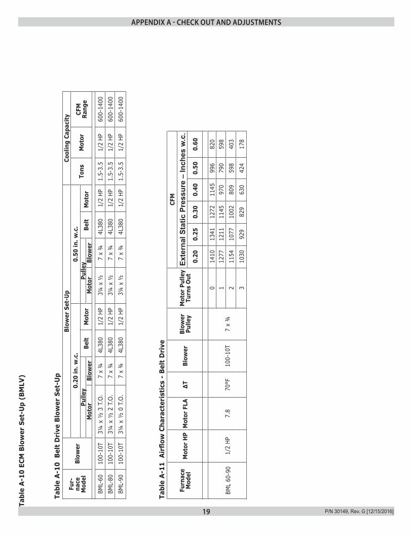
Tabl
e A
-10
ECM
Blo
wer
Set
-Up
(BM
LV)
Tabl
e A
-10
Bel
t D
rive
Blo
wer
Set
-Up
Fur-
nace
M
odel
Blow
er
Blow
er S
et-U
pCo
olin
g Ca
paci
ty0.
20 in
. w.c
.0.
50 in
. w.c
.To
nsM
otor
CFM
Ra
nge
Pulle
yBe
ltM
otor
Pulle
yBe
ltM
otor
Mot
orBl
ower
Mot
orBl
ower
BML-
6010
0-10
T3¼
x ½
3 T
.O.
7 x
¾4L
380
1/2
HP3¼
x ½
7 x
¾4L
380
1/2
HP1.
5-3.
51/
2 HP
600-
1400
BML-
8010
0-10
T3¼
x ½
2 T
.O.
7 x
¾4L
380
1/2
HP3¼
x ½
7 x
¾4L
380
1/2
HP1.
5-3.
51/
2 HP
600-
1400
BML-
9010
0-10
T3¼
x ½
0 T
.O.
7 x
¾4L
380
1/2
HP3¼
x ½
7 x
¾4L
380
1/2
HP1.
5-3.
51/
2 HP
600-
1400
Tabl
e A
-11
Air
flow
Cha
ract
eris
tics
- B
elt
Dri
ve
Furn
ace
Mod
elM
otor
HP
Mot
or F
LA∆T
Blow
erBl
ower
Pu
lley
Mot
or P
ulle
y Tu
rns
Out
CFM
Exte
rnal
Sta
tic P
ress
ure
– In
ches
w.c
.0.
200.
250.
300.
400.
500.
60
BML
60-9
01/
2 HP
7.8
70°F
100-
10T
7 x
¾
014
1013
4112
7211
4599
682
01
1277
1211
1145
970
790
598
211
5410
7710
0280
959
840
3
310
3092
982
963
042
417
8
APPENDIX A - CHECK OUT AND ADJUSTMENTS
20 P/N 30149, Rev. G [12/15/2016]
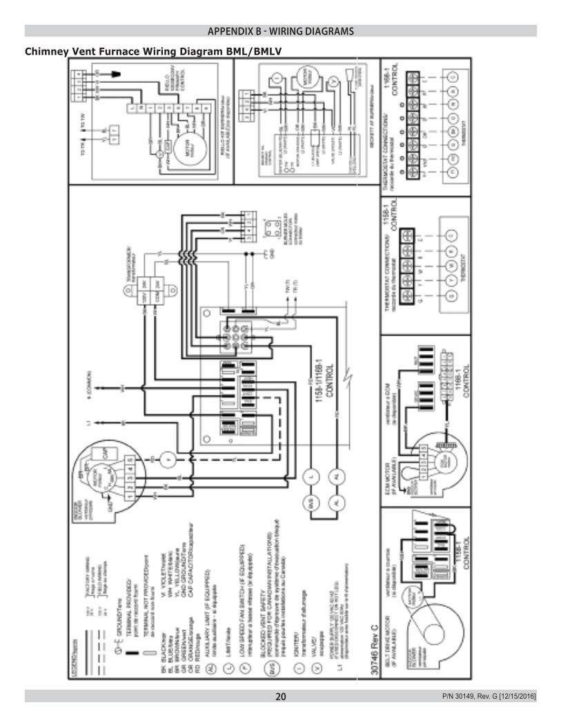
APPENDIX B - WIRING DIAGRAMS
Chimney Vent Furnace Wiring Diagram BML/BMLV

21 P/N 30149, Rev. G [12/15/2016]
APPENDIX B - WIRING DIAGRAMS
Direct Vent Furnace Wiring Diagram BML/BMLV

22 P/N 30149, Rev. G [12/15/2016]
Table C-1: 1158-120 Electronic Fan Timer Board (EFT) Detailed Sequence Of Operation (BML)Mode Action System Response
HEAT
Thermostat calls for heat. ("W" terminal is energized).
EFT closes the oil primary control T - T connections.Ignition system and the oil primary control start the furnace. Oil flows as long as the oil primary control senses flame.Burner motor is energized and heat "fan on" delay timing begins. When timing is complete, the circulator fan is energized at heat speed.
Thermostat ends call for heat. ("W" terminal is de-energized).
The oil primary control is de-energized, terminating the burner cycle.Heat "fan off" delay timing begins. Length of delay depends on EFT dipswitch settings. When timing is complete, the circulator fan is de-energized.EFT returns to standby mode, (Oil primary control and circulator fan are off, unless continuous fan operation is selected at the thermostat).
Burner fails to light.Oil primary control locks out within lockout timing, (15 seconds).Burner motor is de-energized. (Even though thermostat is still calling for heat).If circulator fan has started, it continues through the selected heat “fan off” delay period.
Established flame fails.Burner motor is de-energized and oil primary control goes into recycle mode.If the selected heat “fan off” delay timing is longer than the recycle delay timing, the circulator fan continues to run through the next trial for ignition.
COOL
Thermostat begins call for cool. (G and Y terminals are ener-gized).
Cooling contactor is energized immediately.Circulator fan is energized at cool speed.
Thermostat ends call for cool. (G and Y terminals are de-ener-gized).
Cooling contactor is de-energized immediately.Circulator fan turns off immediately.
FAN
Thermostat begins call for fan. (G terminal is energized). Circulator fan is energized immediately at cooling speed.
Thermostat ends call for fan. (G terminal is de-energized). Circulator fan is de-energized immediately.
LIMIT
Limit switch string opens.
Oil primary control shuts off burner.Circulator fan is energized immediately at heat speed.EFT opens the oil primary control T - T connections. Circulating fan runs as long as limit string stays open.If there is a call for cooling or fan, the circulating fan switches from heating to cooling speed.
Limit switch string closes (with existing call for heat).
EFT begins heat “fan off” delay sequence.Circulating fan turns off after the selected heat “fan off” timing.EFT re-closes the oil primary control T - T connections.Oil primary control is energized, initiating burner light off.
Limit switch string closes (with-out existing call for heat).
Circulator fan turns off when heat “fan off” delay time is complete.Normal operation resumes; EFT control is in standby mode awaiting next thermostat com-mand.
FAN Continuous circulating fan is con-nected.
Circulating fan is energized when there is no call for heat, cool, or fan.If fan operation is required by a call for heat, cool, or fan, the EFT switches off the continuous fan speed tap before energizing the other fan speed.
EAC Electronic Air Cleaner is con-nected.
Electronic air cleaner (EAC) connections are energized when the heat or cool speed of the cir-culator fan is energized. EAC connections are not energized when the optional continuous fan terminal is energized.
HUM Humidity control is connected. Humidifier connections are energized when the oil burner motor is energized.
1168-1 Electronic Fan Timer Board (EFT) Detailed Sequence Of Operation (BMLV)
Thermostat Input LEDs (LED1-5, LED8)Six green LEDs are placed behind their respective thermostat connections (Y1, Y/Y2, G, DH, O, and W) and operate whenever a call is present.Thermostat calls for heat “W”. The 24VAC input signal is passed to pin 2 of P1 and will drive the K1 relay that provides dedicated contacts to the T-T input of the Oil Primary Control. Thermostat calls for cool “Y1”. The 24VAC input signal is passed to pin 6 of P1. Thermostat calls for fan “G”. The 24VAC input signal is passed to pin 15 of P1. Thermostat calls for dehumidification “DH”. The 24VAC input signal is passed to pin 10 of P1. Thermostat calls for reversing valve “O”. The 24VAC input signal is passed to pin 9 of P1.
APPENDIX C - SEQUENCE OF OPERATION AND TROUBLESHOOTING
23 P/N 30149, Rev. G [12/15/2016]
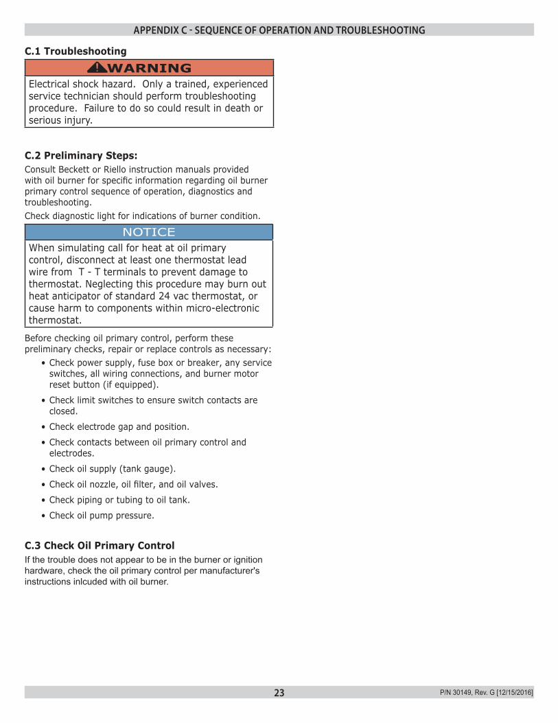
C.1 Troubleshooting
WARNINGElectrical shock hazard. Only a trained, experienced service technician should perform troubleshooting procedure. Failure to do so could result in death or serious injury.
!
C.2 Preliminary Steps:Consult Beckett or Riello instruction manuals provided with oil burner for specific information regarding oil burner primary control sequence of operation, diagnostics and troubleshooting.Check diagnostic light for indications of burner condition.
NOTICEWhen simulating call for heat at oil primary control, disconnect at least one thermostat lead wire from T - T terminals to prevent damage to thermostat. Neglecting this procedure may burn out heat anticipator of standard 24 vac thermostat, or cause harm to components within micro-electronic thermostat.
Before checking oil primary control, perform these preliminary checks, repair or replace controls as necessary:
• Check power supply, fuse box or breaker, any service switches, all wiring connections, and burner motor reset button (if equipped).
• Check limit switches to ensure switch contacts are closed.
• Check electrode gap and position.
• Check contacts between oil primary control and electrodes.
• Check oil supply (tank gauge).
• Check oil nozzle, oil filter, and oil valves.
• Check piping or tubing to oil tank.
• Check oil pump pressure.
C.3 Check Oil Primary ControlIf the trouble does not appear to be in the burner or ignition hardware, check the oil primary control per manufacturer's instructions inlcuded with oil burner.
APPENDIX C - SEQUENCE OF OPERATION AND TROUBLESHOOTING
24 P/N 30149, Rev. G [12/15/2016]
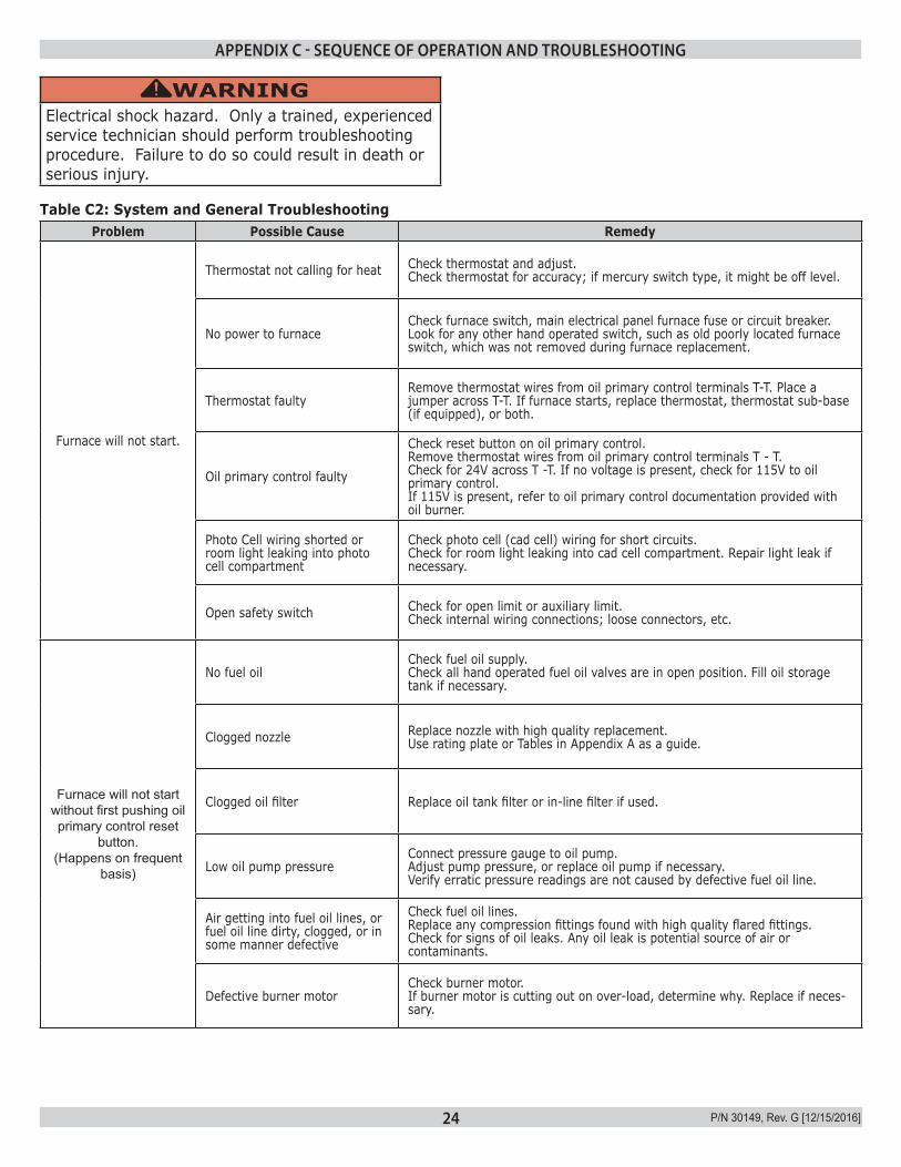
Table C2: System and General TroubleshootingProblem Possible Cause Remedy
Furnace will not start.
Thermostat not calling for heat Check thermostat and adjust.Check thermostat for accuracy; if mercury switch type, it might be off level.
No power to furnaceCheck furnace switch, main electrical panel furnace fuse or circuit breaker. Look for any other hand operated switch, such as old poorly located furnace switch, which was not removed during furnace replacement.
Thermostat faultyRemove thermostat wires from oil primary control terminals T-T. Place a jumper across T-T. If furnace starts, replace thermostat, thermostat sub-base (if equipped), or both.
Oil primary control faulty
Check reset button on oil primary control. Remove thermostat wires from oil primary control terminals T - T. Check for 24V across T -T. If no voltage is present, check for 115V to oil primary control. If 115V is present, refer to oil primary control documentation provided with oil burner.
Photo Cell wiring shorted or room light leaking into photo cell compartment
Check photo cell (cad cell) wiring for short circuits. Check for room light leaking into cad cell compartment. Repair light leak if necessary.
Open safety switch Check for open limit or auxiliary limit. Check internal wiring connections; loose connectors, etc.
Furnace will not start without first pushing oil primary control reset
button.(Happens on frequent
basis)
No fuel oilCheck fuel oil supply. Check all hand operated fuel oil valves are in open position. Fill oil storage tank if necessary.
Clogged nozzle Replace nozzle with high quality replacement. Use rating plate or Tables in Appendix A as a guide.
Clogged oil filter Replace oil tank filter or in-line filter if used.
Low oil pump pressureConnect pressure gauge to oil pump. Adjust pump pressure, or replace oil pump if necessary. Verify erratic pressure readings are not caused by defective fuel oil line.
Air getting into fuel oil lines, or fuel oil line dirty, clogged, or in some manner defective
Check fuel oil lines. Replace any compression fittings found with high quality flared fittings. Check for signs of oil leaks. Any oil leak is potential source of air or contaminants.
Defective burner motorCheck burner motor.If burner motor is cutting out on over-load, determine why. Replace if neces-sary.
WARNINGElectrical shock hazard. Only a trained, experienced service technician should perform troubleshooting procedure. Failure to do so could result in death or serious injury.
!
APPENDIX C - SEQUENCE OF OPERATION AND TROUBLESHOOTING
25 P/N 30149, Rev. G [12/15/2016]
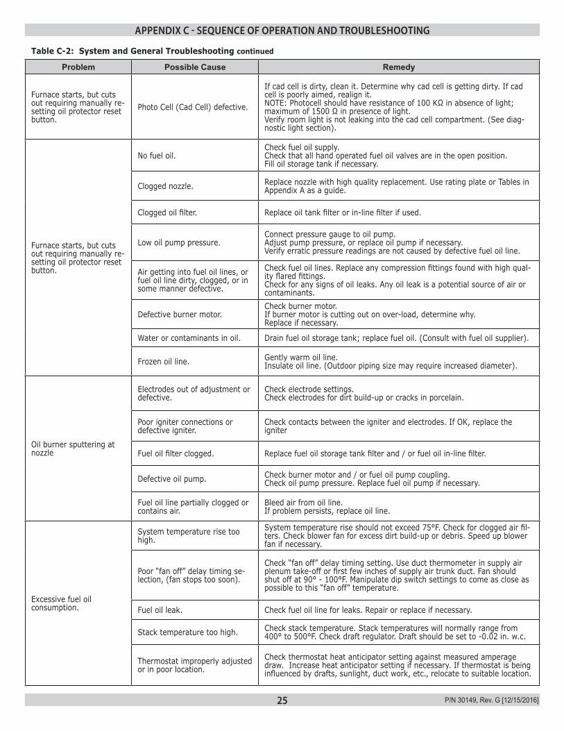
Table C-2: System and General Troubleshooting continued
Problem Possible Cause Remedy
Furnace starts, but cuts out requiring manually re-setting oil protector reset button.
Photo Cell (Cad Cell) defective.
If cad cell is dirty, clean it. Determine why cad cell is getting dirty. If cad cell is poorly aimed, realign it. NOTE: Photocell should have resistance of 100 KΩ in absence of light; maximum of 1500 Ω in presence of light. Verify room light is not leaking into the cad cell compartment. (See diag-nostic light section).
Furnace starts, but cuts out requiring manually re-setting oil protector reset button.
No fuel oil.Check fuel oil supply. Check that all hand operated fuel oil valves are in the open position. Fill oil storage tank if necessary.
Clogged nozzle. Replace nozzle with high quality replacement. Use rating plate or Tables in Appendix A as a guide.
Clogged oil filter. Replace oil tank filter or in-line filter if used.
Low oil pump pressure.Connect pressure gauge to oil pump. Adjust pump pressure, or replace oil pump if necessary. Verify erratic pressure readings are not caused by defective fuel oil line.
Air getting into fuel oil lines, or fuel oil line dirty, clogged, or in some manner defective.
Check fuel oil lines. Replace any compression fittings found with high qual-ity flared fittings. Check for any signs of oil leaks. Any oil leak is a potential source of air or contaminants.
Defective burner motor.Check burner motor. If burner motor is cutting out on over-load, determine why. Replace if necessary.
Water or contaminants in oil. Drain fuel oil storage tank; replace fuel oil. (Consult with fuel oil supplier).
Frozen oil line. Gently warm oil line. Insulate oil line. (Outdoor piping size may require increased diameter).
Oil burner sputtering at nozzle
Electrodes out of adjustment or defective.
Check electrode settings. Check electrodes for dirt build-up or cracks in porcelain.
Poor igniter connections or defective igniter.
Check contacts between the igniter and electrodes. If OK, replace the igniter
Fuel oil filter clogged. Replace fuel oil storage tank filter and / or fuel oil in-line filter.
Defective oil pump. Check burner motor and / or fuel oil pump coupling.Check oil pump pressure. Replace fuel oil pump if necessary.
Fuel oil line partially clogged or contains air.
Bleed air from oil line. If problem persists, replace oil line.
Excessive fuel oil consumption.
System temperature rise too high.
System temperature rise should not exceed 75°F. Check for clogged air fil-ters. Check blower fan for excess dirt build-up or debris. Speed up blower fan if necessary.
Poor “fan off” delay timing se-lection, (fan stops too soon).
Check “fan off” delay timing setting. Use duct thermometer in supply air plenum take-off or first few inches of supply air trunk duct. Fan should shut off at 90° - 100°F. Manipulate dip switch settings to come as close as possible to this “fan off” temperature.
Fuel oil leak. Check fuel oil line for leaks. Repair or replace if necessary.
Stack temperature too high. Check stack temperature. Stack temperatures will normally range from 400° to 500°F. Check draft regulator. Draft should be set to -0.02 in. w.c.
Thermostat improperly adjusted or in poor location.
Check thermostat heat anticipator setting against measured amperage draw. Increase heat anticipator setting if necessary. If thermostat is being influenced by drafts, sunlight, duct work, etc., relocate to suitable location.
APPENDIX C - SEQUENCE OF OPERATION AND TROUBLESHOOTING
26 P/N 30149, Rev. G [12/15/2016]
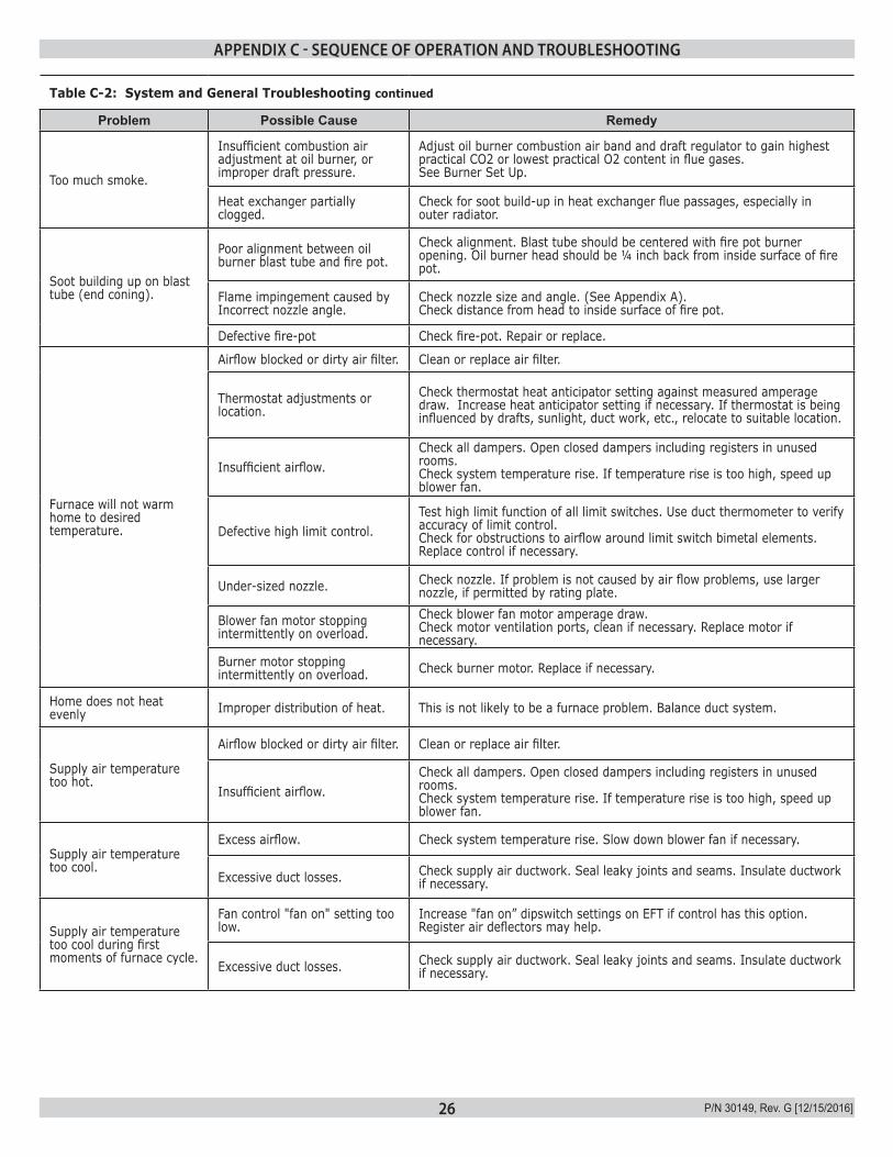
Table C-2: System and General Troubleshooting continued
Problem Possible Cause Remedy
Too much smoke.
Insufficient combustion air adjustment at oil burner, or improper draft pressure.
Adjust oil burner combustion air band and draft regulator to gain highest practical CO2 or lowest practical O2 content in flue gases. See Burner Set Up.
Heat exchanger partially clogged.
Check for soot build-up in heat exchanger flue passages, especially in outer radiator.
Soot building up on blast tube (end coning).
Poor alignment between oil burner blast tube and fire pot.
Check alignment. Blast tube should be centered with fire pot burner opening. Oil burner head should be ¼ inch back from inside surface of fire pot.
Flame impingement caused by Incorrect nozzle angle.
Check nozzle size and angle. (See Appendix A). Check distance from head to inside surface of fire pot.
Defective fire-pot Check fire-pot. Repair or replace.
Furnace will not warm home to desired temperature.
Airflow blocked or dirty air filter. Clean or replace air filter.
Thermostat adjustments or location.
Check thermostat heat anticipator setting against measured amperage draw. Increase heat anticipator setting if necessary. If thermostat is being influenced by drafts, sunlight, duct work, etc., relocate to suitable location.
Insufficient airflow.Check all dampers. Open closed dampers including registers in unused rooms. Check system temperature rise. If temperature rise is too high, speed up blower fan.
Defective high limit control.Test high limit function of all limit switches. Use duct thermometer to verify accuracy of limit control. Check for obstructions to airflow around limit switch bimetal elements. Replace control if necessary.
Under-sized nozzle. Check nozzle. If problem is not caused by air flow problems, use larger nozzle, if permitted by rating plate.
Blower fan motor stopping intermittently on overload.
Check blower fan motor amperage draw. Check motor ventilation ports, clean if necessary. Replace motor if necessary.
Burner motor stopping intermittently on overload. Check burner motor. Replace if necessary.
Home does not heat evenly Improper distribution of heat. This is not likely to be a furnace problem. Balance duct system.
Supply air temperature too hot.
Airflow blocked or dirty air filter. Clean or replace air filter.
Insufficient airflow.Check all dampers. Open closed dampers including registers in unused rooms. Check system temperature rise. If temperature rise is too high, speed up blower fan.
Supply air temperature too cool.
Excess airflow. Check system temperature rise. Slow down blower fan if necessary.
Excessive duct losses. Check supply air ductwork. Seal leaky joints and seams. Insulate ductwork if necessary.
Supply air temperature too cool during first moments of furnace cycle.
Fan control "fan on" setting too low.
Increase "fan on” dipswitch settings on EFT if control has this option. Register air deflectors may help.
Excessive duct losses. Check supply air ductwork. Seal leaky joints and seams. Insulate ductwork if necessary.
APPENDIX C - SEQUENCE OF OPERATION AND TROUBLESHOOTING
27 P/N 30149, Rev. G [12/15/2016]
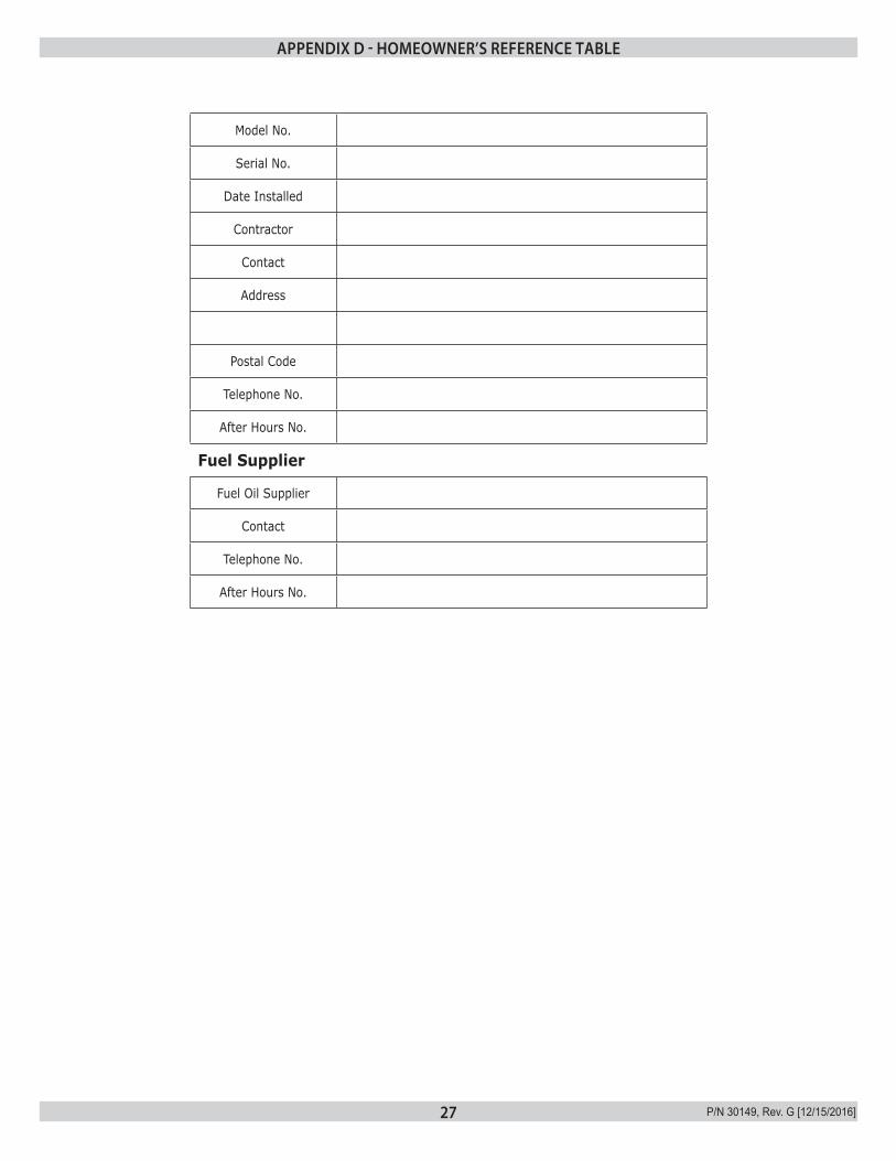
Model No.
Serial No.
Date Installed
Contractor
Contact
Address
Postal Code
Telephone No.
After Hours No.
Fuel Supplier
Fuel Oil Supplier
Contact
Telephone No.
After Hours No.
APPENDIX D - HOMEOWNER’S REFERENCE TABLE
28 P/N 30149, Rev. G [12/15/2016]
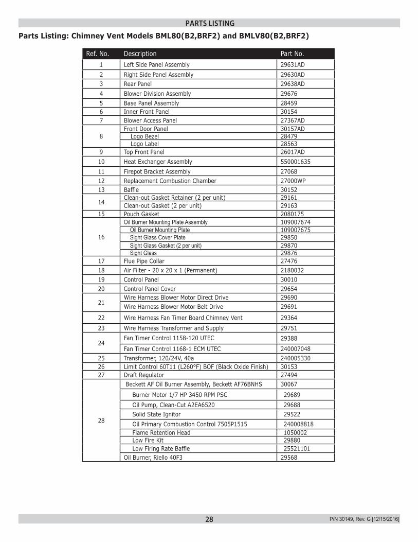
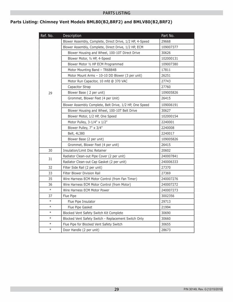
Parts Listing: Chimney Vent Models BML80(B2,BRF2) and BMLV80(B2,BRF2)
Ref. No. Description Part No.1 Left Side Panel Assembly 29631AD2 Right Side Panel Assembly 29630AD3 Rear Panel 29638AD4 Blower Division Assembly 296765 Base Panel Assembly 284596 Inner Front Panel 301547 Blower Access Panel 27367AD
8Front Door Panel 30157AD Logo Bezel 28479 Logo Label 28563
9 Top Front Panel 26017AD10 Heat Exchanger Assembly 55000163511 Firepot Bracket Assembly 2706812 Replacement Combustion Chamber 27000WP13 Baffle 30152
14Clean-out Gasket Retainer (2 per unit) 29161Clean-out Gasket (2 per unit) 29163
15 Pouch Gasket 2080175
16
Oil Burner Mounting Plate Assembly 109007674Oil Burner Mounting Plate 109007675Sight Glass Cover Plate 29850Sight Glass Gasket (2 per unit) 29870Sight Glass 29876
17 Flue Pipe Collar 2747618 Air Filter - 20 x 20 x 1 (Permanent) 218003219 Control Panel 3001020 Control Panel Cover 29654
21Wire Harness Blower Motor Direct Drive 29690Wire Harness Blower Motor Belt Drive 29691
22 Wire Harness Fan Timer Board Chimney Vent 2936423 Wire Harness Transformer and Supply 29751
24Fan Timer Control 1158-120 UTEC 29388
Fan Timer Control 1168-1 ECM UTEC 24000704825 Transformer, 120/24V, 40a 24000533026 Limit Control 60T11 (L260°F) BOF (Black Oxide Finish) 3015327 Draft Regulator 27494
28
Beckett AF Oil Burner Assembly, Beckett AF76BNHS 30067
Burner Motor 1/7 HP 3450 RPM PSC 29689 Oil Pump, Clean-Cut A2EA6520 29688 Solid State Ignitor 29522 Oil Primary Combustion Control 7505P1515 240008818 Flame Retention Head 1050002 Low Fire Kit 29880 Low Firing Rate Baffle 25521101
Oil Burner, Riello 40F3 29568
PARTS LISTING
29 P/N 30149, Rev. G [12/15/2016]
Parts Listing: Chimney Vent Models BML80(B2,BRF2) and BMLV80(B2,BRF2)
Ref. No. Description Part No.
29
Blower Assembly, Complete, Direct Drive, 1/2 HP, 4-Speed 29668Blower Assembly, Complete, Direct Drive, 1/2 HP, ECM 109007377 Blower Housing and Wheel, 100-10T Direct Drive 30626 Blower Motor, ½ HP, 4-Speed 102000131 Blower Motor ½ HP ECM Programmed 109007380 Motor Mounting Band – TR6884B 17811 Motor Mount Arms – 10-10 DD Blower (3 per unit) 26251 Motor Run Capacitor, 10 mfd @ 370 VAC 27743 Capacitor Strap 27760 Blower Base ( 2 per unit) 109005826 Grommet, Blower Feet (4 per Unit) 26415
Blower Assembly Complete, Belt Drive, 1/2 HP, One Speed 109006191 Blower Housing and Wheel, 100-10T Belt Drive 30627 Blower Motor, 1/2 HP, One Speed 102000154
Motor Pulley, 3-1/4" x 1/2" 2240001 Blower Pulley, 7" x 3/4" 2240008 Belt, 4L380 2240017 Blower Base (2 per unit) 109005826 Grommet, Blower Feet (4 per unit) 26415
30 Insulation/Limit Disc Retainer 20602
31Radiator Clean-out Pipe Cover (2 per unit) 240007841Radiator Clean-out Cap Gasket (2 per unit) 240006333
32 Filter Side Rail (2 per unit) 2737033 Filter Blower Division Rail 2736935 Wire Harness ECM Motor Control (from Fan Timer) 24000727636 Wire Harness ECM Motor Control (from Motor) 240007272* Wire Harness ECM Motor Power 24000727337 Flue Pipe 3002356* Flue Pipe Insulator 29713* Flue Pipe Gasket 21994* Blocked Vent Safety Switch Kit Complete 30690* Blocked Vent Safety Switch - Replacement Switch Only 30660* Flue Pipe for Blocked Vent Safety Switch 30655* Door Handle (2 per unit) 28673
PARTS LISTING
30 P/N 30149, Rev. G [12/15/2016]
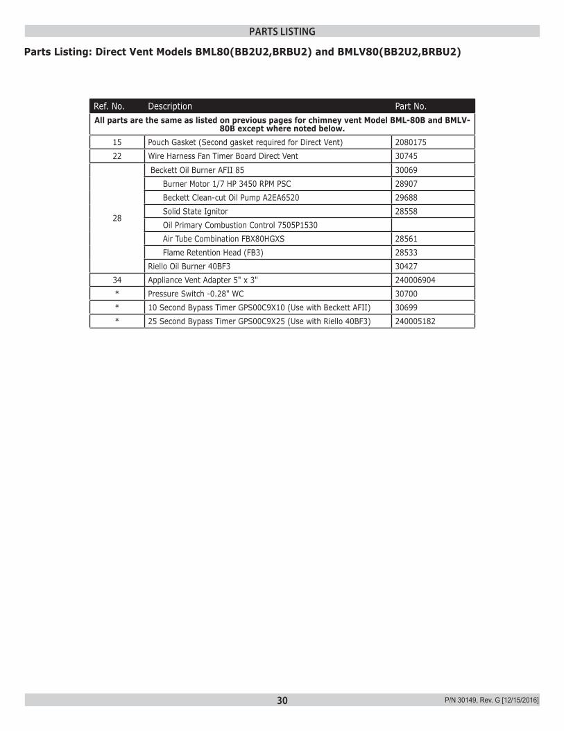
Ref. No. Description Part No.All parts are the same as listed on previous pages for chimney vent Model BML-80B and BMLV-
80B except where noted below.15 Pouch Gasket (Second gasket required for Direct Vent) 208017522 Wire Harness Fan Timer Board Direct Vent 30745
28
Beckett Oil Burner AFII 85 30069 Burner Motor 1/7 HP 3450 RPM PSC 28907 Beckett Clean-cut Oil Pump A2EA6520 29688 Solid State Ignitor 28558 Oil Primary Combustion Control 7505P1530 Air Tube Combination FBX80HGXS 28561 Flame Retention Head (FB3) 28533Riello Oil Burner 40BF3 30427
34 Appliance Vent Adapter 5" x 3" 240006904* Pressure Switch -0.28" WC 30700* 10 Second Bypass Timer GPS00C9X10 (Use with Beckett AFII) 30699* 25 Second Bypass Timer GPS00C9X25 (Use with Riello 40BF3) 240005182
Parts Listing: Direct Vent Models BML80(BB2U2,BRBU2) and BMLV80(BB2U2,BRBU2)
PARTS LISTING
31 P/N 30149, Rev. G [12/15/2016]
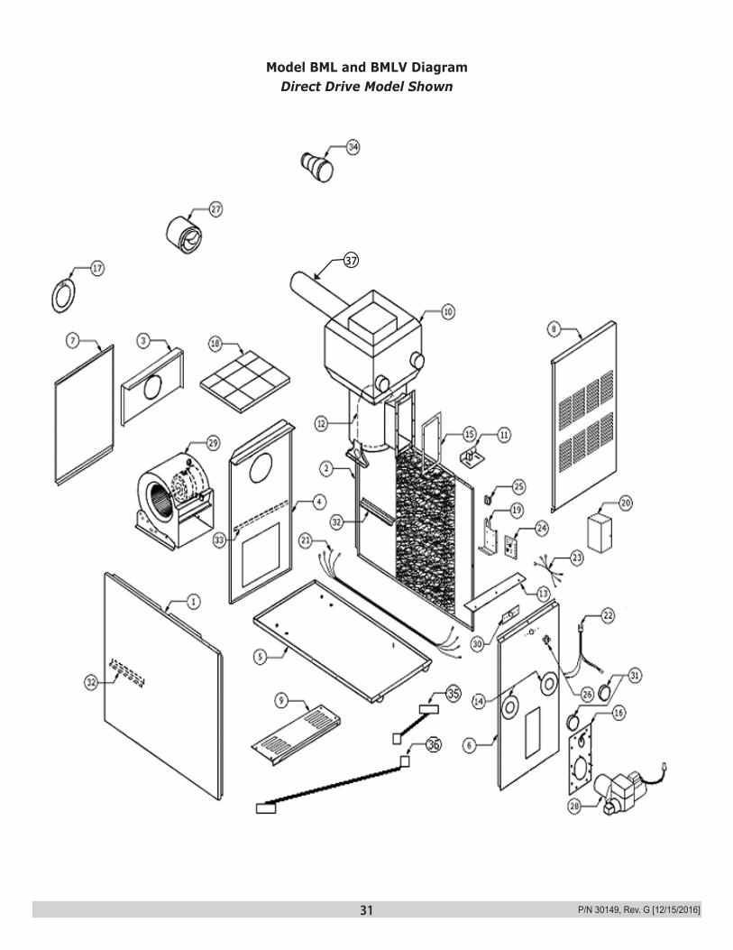
Model BML and BMLV DiagramDirect Drive Model Shown
37

P/N 30149, Rev. G [12/15/2016]
ECR International 2210 Dwyer Avenue, Utica NY 13501web site: www.ecrinternational.com