BMI Racing Copperhead 10 Manual - CompetitionX...Message from BMI Racing * The Copperhead 10 was...
12
Version 1.00 4-2-2010
Transcript of BMI Racing Copperhead 10 Manual - CompetitionX...Message from BMI Racing * The Copperhead 10 was...

Version 1.00 4-2-2010

1. .050”, 1/16” and 3/32” Allen wrenches
2. A #2 Phillips Screwdriver
3. 3/16” and 11/32” nut drivers
4. A pair of needle nose pliers
5. A pair of slip join pliers
6. A hobby knife
7. A ruler or calipers
8. A file
9. A soldering iron
10. Diff Grease
11. Electric Motor Cleaner Spray
12. 40wt silicon shock oil (for center shock)
13. 10,000wt silicon diff oil (for damper tubes)
Items needed to assemble your Copperhead 10
1. Two channel surface Radio system
2. A servo*
3. One or more 4 cell battery packs
4. A battery charger
5. An electronic speed control
6. An electric motor
7. A 64 pitch pinion gear
8. A small servo saver.
9. A 200m 1/10th scale body
10. 1/10th foam tires scale tires
Items needed to operate your Copperhead 10
Message from BMI Racing
* The Copperhead 10 was designed to use mini servos. While any servo will fit the ideal weight distribution is best achieved with a min servo such as the Futaba 9602, 3650, JR 3650, etc.
The Copperhead 10 is the first 2nd generation World GT car. After two years of racing and testing we had more than few good ideas that we wanted to incorporate in our next World GT car. As the concept for the new car started to come together we realized this was not going to be a DB10RRR. There we too many subtle tweaks, changes in suspension geometry, altering the chassis torsional stiffness as well as optimizing the car for the latest Brushless/LiPo power systems. The result of all of this is the Copperhead 10. This car is everything the DB 10R was and much, much more. All the changes focused on expanding the cars setup envelope. This means its is easier to get the car setup on a wider variety of surfaces. From club races on low grip parking lot tracks to the carpet at the A-Main of the Snowbird Nationals, the Copperhead 10 can easily be setup to win.
Please read through the instruction manual carefully. Even if you are an experienced R/C racer, there are some details about the Copperhead 10 that are different. To get the most out of your kit you must have it assembled correctly.
With Regards,
Jason Breiner
BMI Racing

Front suspension assembly
Locate your lower front suspension arms and the hard anodized alloy pivot balls. Note that the arms are not symmetrical.
Pop the pivot balls into the arms with the shoulder on the ball facing up. Do this by placing the ball on a hard flat surface and placing the arm over the ball. Carefully push the arm down over the pivot ball. Be careful. It will take a lot of force.
Special Note:The best way to install the pivot balls is with an IRS pivot ball tool (www.teamirsrc.com, IRS1376). If the pivot balls are tight you can over tighten this tool, after the ball snaps in, a little at a time until the ball moves freely.
Locate your upper suspension arm rod ends. Note that the top side of the rod end opening is smaller than the bottom
With a hobby knife, carefully chamfer the top of the rod ends opening. This creates clearance for the king pin shims that will go here later. This will ensure there is no binding in the suspension.
The inset picture shows a finished rod end.
Step 1
Step 2
Locate the two remaining hard anodized alloy pivot balls and snap them into the upper arm rod ends with the shoulder on the ball facing down. As with the lower arms, squeeze the rod ends if the balls do not move freely.
Locate the upper suspension arms, the upper arm turnbuckles and assemble as shown above.
We prefer to thread the right hand thread portions of the turnbuckles into the rod ends and the left hand thread into the upper arms.
Note: The arms have a bottom and a top. They have small circular impressions on the bottoms.
Step 3
Step 4
Step 5
Locate the 10 degree reactive caster upper suspension mounts, upper suspension hinge pin, e-clip and nylon caster spacers.
Assemble as shown.
Make sure the upper suspension arms pivots freely. If there is any binding at all, the car may handle poorly. If the upper arms are tight, use the back of a hobby knife to scrape the front and back of the reactive caster blocks and the inside of the upper suspension arms to make more clearance for the caster spacers. Take your time here and get it right!
Special Note:The Copperhead 10 uses IRS upper hinge pins and does not require setscrews in the upper suspension arm mounts.
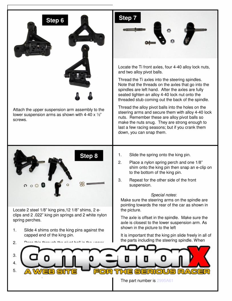
Step 6
Attach the upper suspension arm assembly to the lower suspension arms as shown with 4-40 x ½” screws.
Step 7
Locate the Ti front axles, four 4-40 alloy lock nuts, and two alloy pivot balls.
Thread the Ti axles into the steering spindles. Note that the threads on the axles that go into the spindles are left hand. After the axles are fully seated tighten an alloy 4-40 lock nut onto the threaded stub coming out the back of the spindle.
Thread the alloy pivot balls into the holes on the steering arms and secure them with alloy 4-40 lock nuts. Remember these are alloy pivot balls so make the nuts snug. They are strong enough to last a few racing seasons; but if you crank them down, you can snap them.
Step 8
1. Slide 4 shims onto the king pins against the capped end of the king pin.
2. Pass this through the pivot ball in the upper suspension arms rod end.
3. Place one more shim on the king pin.
4. Slide the steering spindle onto the king pin.
5. Slide the king pin through the pivot ball in the lower suspension arm.
1. Slide the spring onto the king pin.
2. Place a nylon spring perch and one 1/8” shim onto the king pin then snap an e-clip on to the bottom of the king pin.
3. Repeat for the other side of the front suspension.
Locate 2 steel 1/8” king pins,12 1/8” shims, 2 e-clips and 2 .022” king pin springs and 2 white nylon spring perches.
Special notes:Make sure the steering arms on the spindle are pointing towards the rear of the car as shown in the picture.
The axle is offset in the spindle. Make sure the axle is closest to the lower suspension arm. As shown in the picture to the left
It is important that the king pin slide freely in all of the parts including the steering spindle. When you thread the axle into the spindle, it may swell the king pin bore and make it tight on the spindle. You can try to use a 1/8” drill to open it up but the best solution is to use a 1/8” reamer.
You can order the reamer from: www.mcmaster.com.
The part number is 2995A61

Step 9
Take a minute to prepare all your carbon components for assembly. With a file or sand paper knock off any sharp edges along the perimeter or the carbon parts.
Special note:Carbon fiber dust is really bad for you. Always wear a mask and eye protection when sanding or filing carbon fiber.
Step 10
Note that the Track Width Adjuster plates have the large holes chamfered on one side. This is to provide clearance for the heads of the 8-32 screws that hold the front suspension to the lower chassis. Make sure these face down towards the chassis in all assembly steps.
Thread 2 ¼” 4-40 button head screws into the track adjuster plate as shown. Make them stick out the bottom ~1/16” (1.5mm). These screws will key into holes in the lower chassis to provide alignment at different width settings.
Step 11
Pass a 4-40 x 3/8” flat head screw through the bottom of the chassis and track adjuster plate. Secure it with an alloy lock nut.
Locate four 8-32 x 5/8” screws and 4 thick nylon lower suspension arm risers.
Pass a screw through the chassis, a track adjuster plate and slide a thick nylon riser over the screw. Start threading the screw into the lower suspension arm but do not tighten it. Pass another screw through the chassis and adjuster plate and slide a thick nylon riser over that screw. Start threading the screw into the other hole on the lower suspension arm. Tighten both screws. Repeat on the other side.
Special Note:You will have to add or subtract spacers in order to achieve your desired ride height. BMI Racing makes alloy spacers you can get a variety of sizes from www.bmiracing.com, (P/N DB5311-DB5316)
Step 12

Locate two flex plates*, 2 flex plate pivot assemblies and 4 2-56 button head screws.
1.Insert a pivot assembly into a flex plate.
2.Pass the 2-56 screws through the pivot ball assembly from the top so they thread into the flex plate.
3.Repeat for the other flex plate.
Rear suspension assembly
Step 13
Locate the delrin center pivot assembly one 4-40 x ¼” and two 4-40 x 3/8” flat head screws.
Attach the center pivot assembly to the rear most hole in the center of the lower chassis plate with the ¼” screw. The shoulder on the pivot ball and the two bosses on the center pivot assembly should face down towards the chassis. The pivot ball has a 3/32” hex in the top so you can use a wrench to tighten it firmly.
Attach the rear lower pod plate to the center pivot assembly with two 4-40 x 3/8” flat head screws.
Step 14
Step 15
Attach the two flex plate assemblies to thelower pod plate with 4-40 x 1-4: flat head screws. Use the 3/32” hex in the top of the pivot balls to tighten them down firmly.
Locate 2 anodized short non-threaded spacers and 2 4-40 x ½” flat head screws.
1.Pass a 4-40 x ½” flat head screw through the hole in the chassis corresponding to the front hole on the flex plate.
2.Slide the anodized spacer onto the screw.
3. Slide the flex link over the screw and secure it with an alloy lock nut.
4.Repeat to assemble the other side

Step 16
Locate the two alloy rear pod plates, the alloy rear pod plate spacer tube 2 4-40 x 3/8” flat head screws and 4 4-40 x ¼” flat head screws.
Attach the alloy pod plates to the lower carbon pod plate with the 4 4-40 x ¼” screws.
Attach the alloy rear pod plate spacer tube to the allow rear pods with the 2 4-40 x 3/8” screws.
Step 17
Locate and install the two long anodized threaded spacers as shown with 4-40 x ¼” flat head screws
1. Attach the carbon chassis brace to the chassis with 2 4-40 x ¼” flat head screws by threading them into the long alloy threaded posts at the rear corners of the chassis.
2. Attach the alloy pivot balls to the bottom of the pod top plate and the tops pf the side wings as shown above. Secure them with alloy lock nuts
3. Attach a black medium ball stud on top of the top pod plate in the front and center hole. Secure it with an alloy lock nut.
4. Attach the carbon pod top plate to the alloy rear pod plates
Step 18

Step 19Locate the damper tube parts bag, the rear pod top plate and 4 4-40 x ¼” flat head screws..
1.Thread a 4-40 x3/8” set screw into each of the 4 ball cups from the damper parts bag.
2.Thread a ball cup/set screw assembly into the ends of each of the damper tube pistons and damper tubes.
3.Apply 10000wt silicon diff oil to the pistons and insert them into the damper tubes.
4.Snap the ball cups of the assembled damper tubes onto the pivot balls on the pod top plate and wings.
Note:
If you feel play between your ball cups and ball studs, you can place a single layer of plastic bag material between your ball cup and ball stud then snap them together. This will cut and insert a disc of plastic into your ball cup reducing or eliminating the play. If you still feel play, repeat the process.
Attach 2 long alloy stand offs to the chassis in the locations shown with 4-40 x ¼” flat head screws.
Install a short ball stud in the battery retention plate in the hole show in the picture above.
Attach the battery retention plate to the 3 alloy stand offs with 3 4-40 x ¼” flat head screws.
Step 21Step 20

Step 22
Assemble the IRS Nickel-Teflon Macro Shock as per the included instructions with 40wt silicon shock oil.
Trim 1/8” (3mm) from the ball cup that threads onto the shock cap. Thread the ball cups on the ends of the shock so the over all shock length is 3.312” . This length will give you the standard setting of 1.5mm of rear pod droop.
Diff Assembly:
1. Put a small dab of diff grease on the axle flange so the diff will stick to it. Place a diff ring on the flange so its flat keys onto the flat on the diff flange.
2. Place a flanged 3/8 x ¼” bearing in the center of the spur gear. Slide the spur gear and bearing unit on to the axle until it stops against the diff ring.
3. With a small flat screw driver remove the diff balls from the diff grease and snap them into the outer row of holes in the spur gear.
4. Place a flanged 3/8 x ¼” bearing into the inside face of the right side diff hub. Put a small dab of diff grease on the hub flange so the diff will stick to it. Place a diff ring on the flange so its flat keys onto the flat on the hub flange. Slide this unit on to axle.
5. Slide a flanged 3/8 x ¼” bearing over the axle into the outside face of the right side diff hub. Slide the stepped thrust cone onto the axles so the smaller diameter part is against the right hub bearing.
Locate the rear axle parts bag. There are a couple of steps that can make your diff last longer that should be done at this time.
Use the right alloy diff hub as a holder and sand both sides of each diff ring on 600 grit sand paper using electric motor cleaner spray as a lubricant. Sand until you see an even scoring pattern across the face of each diff ring. Clean them with motor spray and set them aside.
The diff balls may have a protective oil coating on them. Place them on a clean paper towel and carefully clean them with motor spray. When dry drop them into your cup of diff grease and stir them to coat them with diff grease.
Step 23
Step 23 Continued
1. Thread the black nylon lock nut onto the threaded stud on the axles until it makes contact with the thrust cone.
2. Tighten the black lock nut gradually with an 11/32” nut driver until you notice you cannot slip the spur gear when holding the axle and right hub in a fixed position.
Six 4-40 x ¼” cap head screws are supplied to mount your rear wheels.
Notes:
Keep you fingers clean with motor spray. Diff assembly is like surgery. You do not want dirt or oil where it does not belong.
The grease on the diff balls when you pluck them out of the cup of diff grease is all you need. Smearing diff grease on the rings will make your diff get dirty faster and make a mess.
The ultimate goal in building a diff is one which is extremely free and glass smooth but requires a lot of force to slip the spur gear.
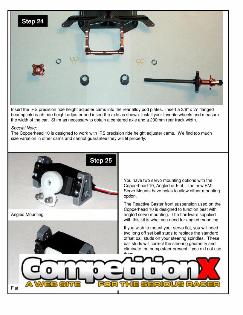
Insert the IRS precision ride height adjuster cams into the rear alloy pod plates. Insert a 3/8” x ¼” flanged bearing into each ride height adjuster and insert the axle as shown. Install your favorite wheels and measure the width of the car. Shim as necessary to obtain a centered axle and a 200mm rear track width.
Special Note:
The Copperhead 10 is designed to work with IRS precision ride height adjuster cams. We find too much size variation in other cams and cannot guarantee they will fit properly.
Step 24
Step 25
Angled Mounting
Flat Mounting
You have two servo mounting options with the Copperhead 10, Angled or Flat. The new BMI Servo Mounts have holes to allow either mounting option.
The Reactive Caster front suspension used on the Copperhead 10 is designed to function best with angled servo mounting. The hardware supplied with this kit is what you need for angled mounting.
If you wish to mount your servo flat, you will need two long off set ball studs to replace the standard offset ball studs on your steering spindles. These ball studs will correct the steering geometry and eliminate the bump steer present if you did not use them.
The servo is mounted to the servo mounts with two 4-40 x ¼” button head screws.

Step 27
Step 28
The Servo mounts are attached to the lower chassis with two 4-40 x ¼” flat head screws.
At this time drill out the center holes on your servo saver (not supplied) for two Nickel Teflon ball studs. Secure them with two 3/16 alloy lock nuts.
Locate two titanium turnbuckles and four black ball cups. Assemble them as shown and adjust them to an over all length of 2.66” (67.5mm). This is a starting point. You will need to reset their length after setting your camber in order to achieve the desired amount of front toe.
Note:
You can use the same plastic bag trick mentioned in Step 18 to remove play in your steering linkage. Remember you want to remove play but still have totally free movement in the links. Any friction at all is unacceptable and will make you car not center properly after steering inputs
Install your body posts with two 4-40 x ½’ flat head screws in the front (the front bumper fits between the lower chassis and the front body mounts) and two 4-40 x ¼” button head screws in the rear.
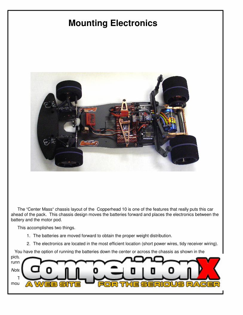
Mounting Electronics
The “Center Mass“ chassis layout of the Copperhead 10 is one of the features that really puts this car ahead of the pack. This chassis design moves the batteries forward and places the electronics between the battery and the motor pod.
This accomplishes two things.
1. The batteries are moved forward to obtain the proper weight distribution.
2. The electronics are located in the most efficient location (short power wires, tidy receiver wiring).
You have the option of running the batteries down the center or across the chassis as shown in the picture. This will give you the option to run your electronics however you may choose. We recommend running them as shown as it did yield the best overall result. However the option is there.
Note:
There is an antenna mount hole in the chassis for racers using non 2.4GHz receivers. An antenna mount is not supplied in the kit.