BMC Cosmic Ray Test Stand Update, Dec. 2001, Steve Ahlen - Boston Univ.
21
BMC Cosmic Ray Test Stand Update, Dec. 2001, Steve Ahlen - Boston Univ. • Gas system installed on Mod-0 (EIL-1) January 2001 • Initial electrical tests January - March 2001 • DAQ set up and debugged April - May 2001 • Data taking on cosmic rays June - August 2001 • Data analysis September - October 2001
-
Upload
colin-rhodes -
Category
Documents
-
view
40 -
download
4
description
BMC Cosmic Ray Test Stand Update, Dec. 2001, Steve Ahlen - Boston Univ. Gas system installed on Mod-0 (EIL-1) January 2001 Initial electrical tests January - March 2001 DAQ set up and debugged April - May 2001 - PowerPoint PPT Presentation
Transcript of BMC Cosmic Ray Test Stand Update, Dec. 2001, Steve Ahlen - Boston Univ.

BMC Cosmic Ray Test StandUpdate, Dec. 2001, Steve Ahlen - Boston Univ.
• Gas system installed on Mod-0 (EIL-1) January 2001
• Initial electrical tests January - March 2001
• DAQ set up and debugged April - May 2001
• Data taking on cosmic rays June - August 2001
• Data analysis September - October 2001
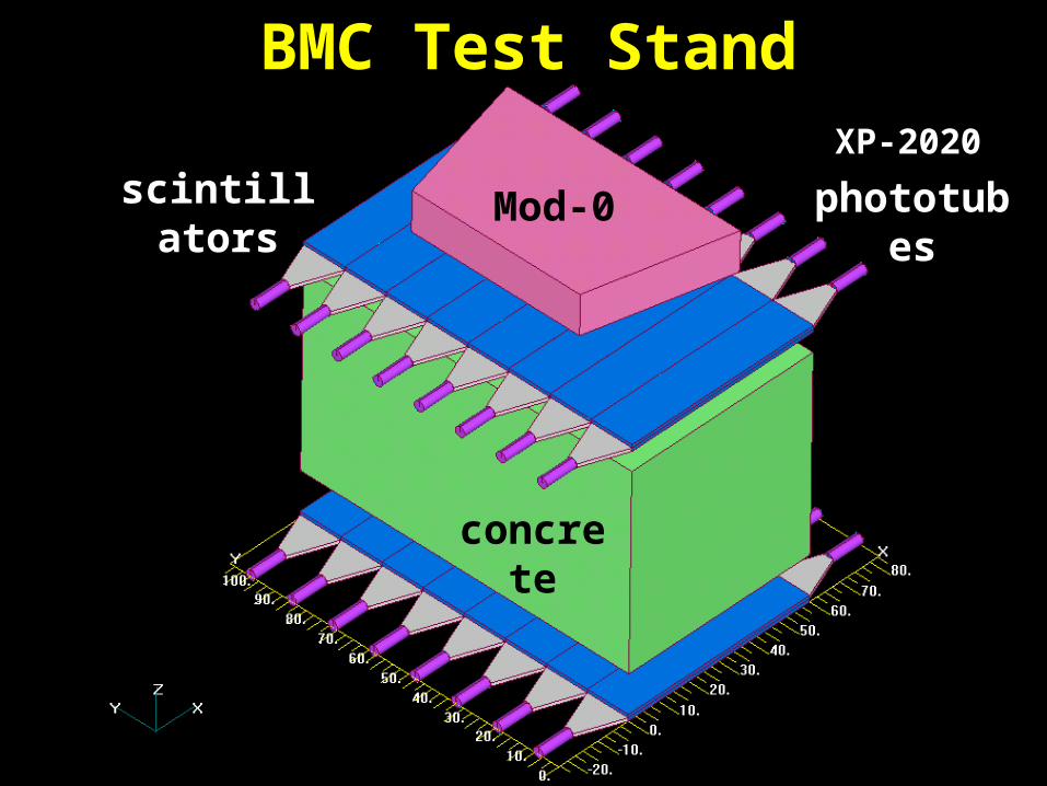
BMC Test Stand
concrete
Mod-0scintillators phototubes
XP-2020

Mod-0 (EIL-1) on combs in clean room
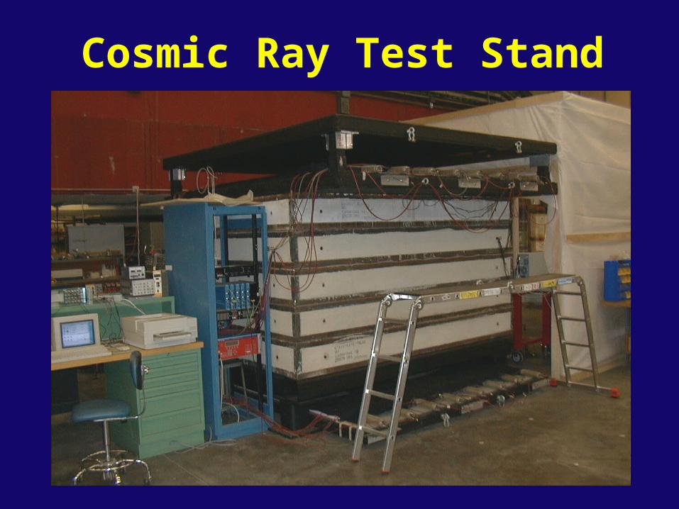
Cosmic Ray Test Stand

Mod-0 on Test Stand

X
Y
Z
V1

mu102201a_g
tdc100 120 140 160 180 200 220 240 260 280 300 320 340 360 380 400 420 440 460 480 500
100
200
300
400
500
600
700
800
mu070201a_c
tdc100 120 140 160 180 200 220 240 260 280 300 320 340 360 380 400 420 440 460 480 500
200
400
600
800
1000
mu102401a_h
tdc100 120 140 160 180 200 220 240 260 280 300 320 340 360 380 400 420 440 460 480 500
200
400
600
800
1000
Threshold = 60 mV flow = 100 sccm
Threshold = 44 mV flow = 100 sccm
Threshold = 44 mV, flow = 500 sccm for 2 days

More timing corrections• Transit time along wire• Time of flight• Trigger time variations due to cable/electronics
variations for bottom scintillator layer
Previous corrections
• TDC card initialization offsets (12.5 ns)
• Clock (synchronization of scintillator and drift tubes)
• Transit of light along bottom scintillator
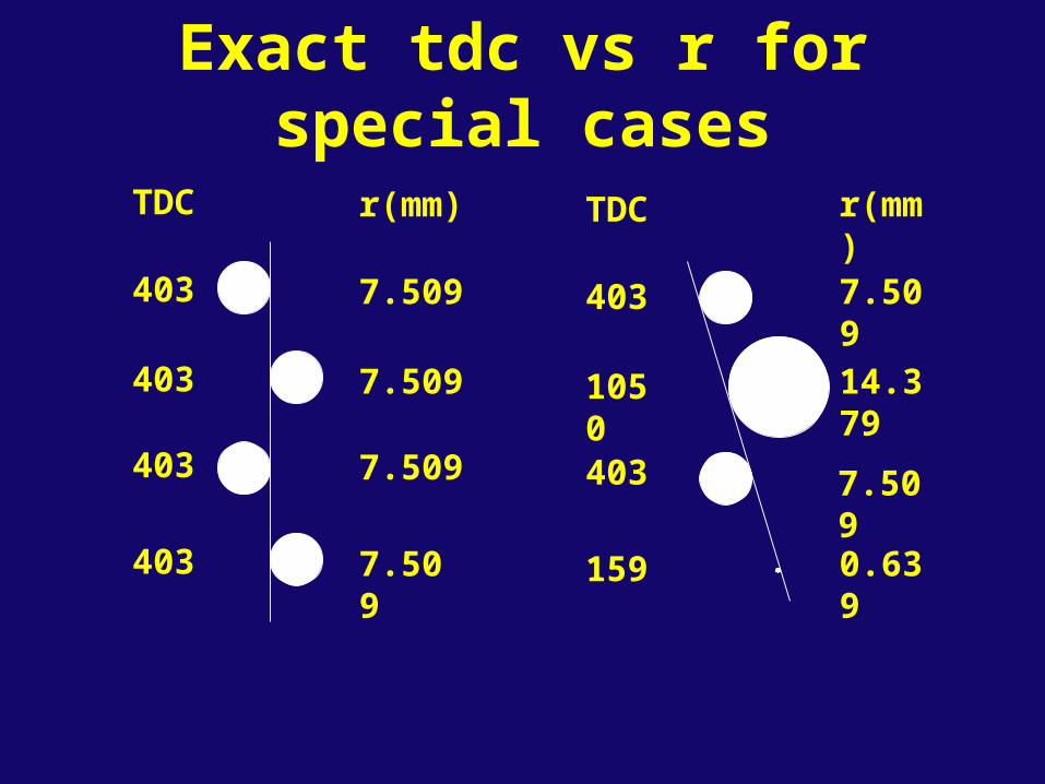
Exact tdc vs r for special cases
TDC
403
403
403
403
r(mm)
7.509
14.379
7.509
0.639
r(mm)
7.509
7.509
7.509
7.509
TDC
403
1050
403
159

0
2
4
6
8
10
12
14
16
0 200 400 600 800 1000 1200 1400
tdc channel
imp
ac
t p
ara
me
ter
r 2nd
exact
Time to distance function with correction factor
15 minutes data from mu062801a

Old Track Fitting• Multilayer (4-tube) fits
– determine the most likely position of the trajectory relative to the drift tube wire (i.e. left or right)
– consider all 16 possibilities for each multilayer
– least squares straight line fit obtained for each possibility
– the fit with the smallest rms residual is kept
• Global 8-tube fit
– use left/right information from multilayer fits
– least squares 8-tube fit
• Global 6-tube fit
– reject two most poorly fit tubes from 8-tube fit (eliminates some delta rays, multiple scatters, small impact parameter fluctuations)
– least squares fit with remaining 6 tubes

X
Y
Z
V1

0
5
10
15
20
25
30
0 100 200 300 400 500
multilayer fit (microns)
the
ta r
ms
(mra
d)
mu070201a_f; theta < 100 mrad
rms multiple scattering angle = 3.5 mrad

0
1
2
3
4
5
6
0 200 400 600 800 1000 1200
xwire(mm)
rms
(mra
d)
mu070201a_f; ML fit rms < 80 microns; theta < 100 mrad
multiple scattering angle larger near beams


-0.499 - -0.494 -0.254 - -0.249 -0.004 - 0.002 0.242 - 0.247 0.491 - 0.497
1000
2000
3000
4000
5000
6000
7000
8000
9000
mu062901a_f; no scintillator cuts
Residuals (mm)
FWHM*1.22/2.35 = 67 microns, MS cut (4 mrad)

mu062901a_f; no scintillator cuts; 97.5% of events
Residuals (mm)
FWHM*1.22/2.35 = 74 microns, no MS cut
-0.997 - -0.987 -0.496 - -0.486 -0.005 - 0.005 0.496 - 0.506 0.997 - 1.007
10000
20000
30000

Resolution Study• Use improved time-to-space function:
– add correction for large impact parameter– add corrections for layer-layer variation
• Select layer not used for track fit
• Best of 128 possibilities for 7 other layers
• Reject worst tube
• Best of 64 possibilities for 6 layers
• Compare fit position with excluded layer’s impact parameter
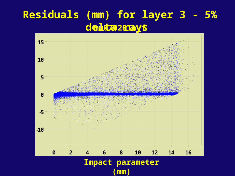
-10
-5
0
5
10
15
0 2 4 6 8 10 12 14 16
mu070201a_f
Impact parameter (mm)
Residuals (mm) for layer 3 - 5% delta rays

impm6
-1
-0.5
0
0.5
1
0 2 4 6 8 10 12 14
mu070201a_f
Impact parameter (mm)
Residuals (mm) for layer 3 (res study)

mu070201a_aj; m6:-.01-.01; chi6<60mic; imp:6.5-9.5mm
Residual (mm)
Residuals for layer 3: FWHM/2.35 = 85 microns
-0.991 - -0.971 -0.492 - -0.472 -0.013 - 0.007 0.486 - 0.506 0.985 - 1.005
100
200


![Micro-BMC development kit user manual R104[1] · Micro-BMC development kit user manual R104[1] ... bmc!!!!! !!](https://static.fdocuments.us/doc/165x107/5e81b1d9bef51d7696139ff7/micro-bmc-development-kit-user-manual-r1041-micro-bmc-development-kit-user-manual.jpg)