
[email protected] ENGR-36_Lec-02_Fa12_Forces_as_Vectorspptx 1 Bruce Mayer, PE Engineering-36:...
40
[email protected] • ENGR-36_Lec-02_Fa12_Forces_as_Vectorspptx 1 Bruce Mayer, PE Engineering-36: Engineering Mechanics - Statics Bruce Mayer, PE Licensed Electrical & Mechanical Engineer [email protected] Engineering 36 Chp 2: Force DeComposition
-
Upload
jean-turner -
Category
Documents
-
view
217 -
download
4
Transcript of [email protected] ENGR-36_Lec-02_Fa12_Forces_as_Vectorspptx 1 Bruce Mayer, PE Engineering-36:...

[email protected] • ENGR-36_Lec-02_Fa12_Forces_as_Vectorspptx1
Bruce Mayer, PE Engineering-36: Engineering Mechanics - Statics
Bruce Mayer, PELicensed Electrical & Mechanical Engineer
Engineering 36
Chp 2: ForceDeCompositi
on
[email protected] • ENGR-36_Lec-02_Fa12_Forces_as_Vectorspptx2
Bruce Mayer, PE Engineering-36: Engineering Mechanics - Statics
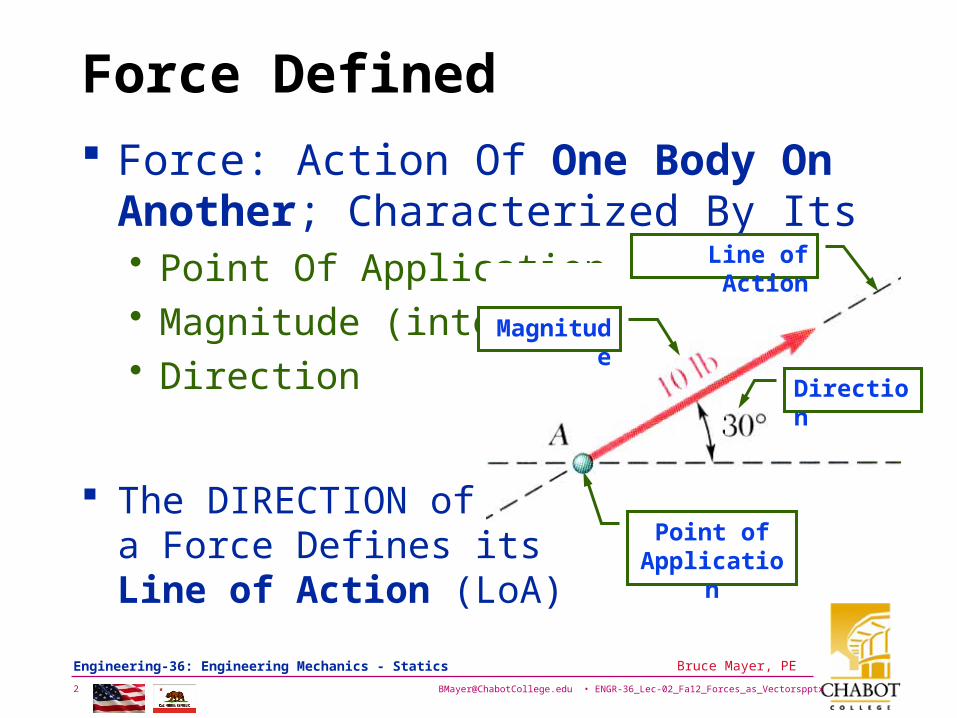
Force Defined
Force: Action Of One Body OnAnother; Characterized By Its • Point Of Application• Magnitude (intensity)• Direction
The DIRECTION of a Force Defines its Line of Action (LoA)
Magnitude
Line of Action
Direction
Point of Application

[email protected] • ENGR-36_Lec-02_Fa12_Forces_as_Vectorspptx3
Bruce Mayer, PE Engineering-36: Engineering Mechanics - Statics
Newton’s Law of Gravitation
Consider two massive bodies Separated by a distance r
M
m
-F
F• Newton’s Gravitation Equation
SCALAR) a (2
Fr
GMmF
– WhereF ≡ mutual force of attraction between 2 bodiesG ≡ universal constant known as the
constant of gravitation (6.673x10⁻¹¹ m3/kg-s2)M, m ≡ masses of the 2 bodies r ≡ distance between the 2 bodies

[email protected] • ENGR-36_Lec-02_Fa12_Forces_as_Vectorspptx4
Bruce Mayer, PE Engineering-36: Engineering Mechanics - Statics
Weight
Consider An Object of mass, m, at a modest Height, h, Above the Surface of the Earth, Which has Radius R• Then the Force on the Object (e.g., Yourself)
gm
R
GMmF
hR
GMmF
22 hRbut
mgW
This Force Exerted by the Earth is called Weight• While g Varies Somewhat With the Elevation &
Location, to a Very Good Approximation– g 9.81 m/s2 32.2 ft/s2

[email protected] • ENGR-36_Lec-02_Fa12_Forces_as_Vectorspptx5
Bruce Mayer, PE Engineering-36: Engineering Mechanics - Statics
Earth Facts
D 7 926 miles (12 756 km) M 5.98 x 1024 kg
• About 2x10¹⁵ EmpireState Buildings
Density, 5 520 kg/m3 • water 1 027 kg/m3
• steel 8 000 kg/m3
• glass 5 300 kg/m3

[email protected] • ENGR-36_Lec-02_Fa12_Forces_as_Vectorspptx6
Bruce Mayer, PE Engineering-36: Engineering Mechanics - Statics
Gravitation Example
Jupiter Moon Europa
Europa Statistics Discovered by Simon Marius & Galileo Galilei Date of discovery 1610 Mass (kg) 4.8e+22 Mass (Earth = 1) 8.0321e-03 Equatorial radius (km) 1,569 Equatorial radius (Earth = 1) 2.4600e-01 Mean density (kg/m^3) 3010 Mean distance from Jupiter (km) 670,900 Rotational period (days) 3.551181 Orbital period (days) 3.551181 Mean orbital velocity (km/sec) 13.74 Orbital eccentricity 0.009 Orbital inclination (degrees) 0.470 Escape velocity (km/sec) 2.02 Visual geometric albedo 0.64 Magnitude (Vo) 5.29
• Find Your Weight on Europra

[email protected] • ENGR-36_Lec-02_Fa12_Forces_as_Vectorspptx7
Bruce Mayer, PE Engineering-36: Engineering Mechanics - Statics
Europa Weight
Since your MASS is SAME on both Earth and Europa need to Find only geu and compare it to gea
Recall
2R
GMg
Europa Statisticsfrom table: Meu = 4.8x10²² kg
Reu = 1 569 km
Then geu
23
22
2
311
101569
1084106736
m
kg
skg
mgeu
..
22
3
12
2211
104622
1084106736
mskg
kgmgeu
.
..
23011 smgeu .
With %Weu = geu/gea
%..
.% 2713
8079
3011Weu
[email protected] • ENGR-36_Lec-02_Fa12_Forces_as_Vectorspptx8
Bruce Mayer, PE Engineering-36: Engineering Mechanics - Statics
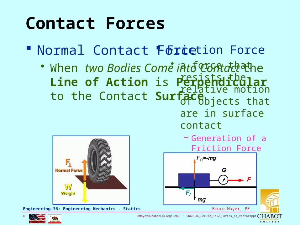
Contact Forces
Normal Contact Force• When two Bodies Come into Contact the
Line of Action is Perpendicular to the Contact Surface
Friction Force• a force that resists the
relative motion of objects that are in surface contact– Generation of a Friction
Force REQUIRES the Presence of a Normal force

[email protected] • ENGR-36_Lec-02_Fa12_Forces_as_Vectorspptx9
Bruce Mayer, PE Engineering-36: Engineering Mechanics - Statics
Contact Forces
Fluid Force• In Fluid Statics the Pressure exerted by the
fluid acts NORMAL to the contact Surface
Tension Force• A PULLING force
which tends to STRETCH an object upon application of the force
pa
p = pa + gd
HMS Bounty
d
[email protected] • ENGR-36_Lec-02_Fa12_Forces_as_Vectorspptx10
Bruce Mayer, PE Engineering-36: Engineering Mechanics - Statics
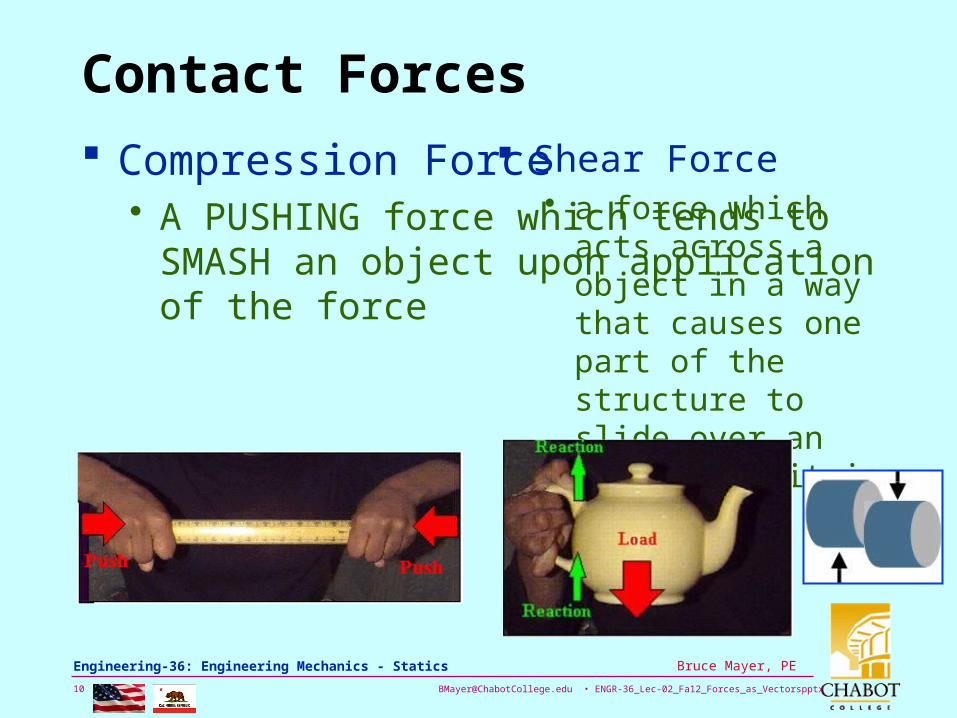
Contact Forces
Compression Force• A PUSHING force which tends to SMASH
an object upon application of the force
Shear Force• a force which acts
across a object in a way that causes one part of the structure to slide over an other when it is applied

[email protected] • ENGR-36_Lec-02_Fa12_Forces_as_Vectorspptx11
Bruce Mayer, PE Engineering-36: Engineering Mechanics - Statics
Recall Free-Body Diagrams
SPACE DIAGRAM A Sketch Showing The Physical Conditions Of The Problem
FREE-BODY DIAGRAM A Sketch Showing ONLY The Forces On The Selected Body

[email protected] • ENGR-36_Lec-02_Fa12_Forces_as_Vectorspptx12
Bruce Mayer, PE Engineering-36: Engineering Mechanics - Statics
Concurrent Forces
CONCURRENT FORCES ≡ Set Of Forces Which All Pass Through The Same Point
When Forces intersect at ONE point then NO TWISTING Action is Generated
In Equil the Vector Force POLYGON must CLOSE
Force Polygonif Static
FBD showing forces P, Q, R, S

[email protected] • ENGR-36_Lec-02_Fa12_Forces_as_Vectorspptx13
Bruce Mayer, PE Engineering-36: Engineering Mechanics - Statics
Vector Notation – Unit Vectors
Unit Vectors have, by definition a Magnitude of 1 (unit Magnitude)
Unit vectors may be • Aligned with the
CoOrd Axes to form a Triad
• Arbitrarily Oriented̂λˆˆˆˆi uukkjji
Unit Vectors may be indicated with “Carets”

[email protected] • ENGR-36_Lec-02_Fa12_Forces_as_Vectorspptx14
Bruce Mayer, PE Engineering-36: Engineering Mechanics - Statics
Example: FBD & Force-PolygonEYE, Not Pulley
A 3500-lb automobile is supported by a cable. A rope is tied to the cable and pulled to center the automobile over its intended position. What is the tension in the rope?
SOLUTION PLAN:• Construct a free-body
diagram for the rope eye at the junction of the rope and cable.– i.e., Make a FBD for the
connection Ring-EYE• Apply the conditions for
equilibrium by creating a closed polygon from the forces applied to the connecting eye.
• Apply trigonometric relations to determine the unknown force magnitudes

[email protected] • ENGR-36_Lec-02_Fa12_Forces_as_Vectorspptx15
Bruce Mayer, PE Engineering-36: Engineering Mechanics - Statics
Example Solution Construct A Free-body
Diagram For The Eye At A. Apply The Conditions For
Equilibrium. Solve For The Unknown Force
Magnitudes Using the Law of the Sines.
58sin
lb3500
2sin120sinACAB TT
lb3570ABT
lb144ACT A pretty Tough Pull for the Guy at C

[email protected] • ENGR-36_Lec-02_Fa12_Forces_as_Vectorspptx16
Bruce Mayer, PE Engineering-36: Engineering Mechanics - Statics
Vector Notation – Vector ID
In Print and Handwriting We Must Distinguish Between• VECTORS• SCALARS
These are Equivalent Vector NotationsPPP P
• Boldface Preferred for Math Processors• Over Arrow/Bar Used for Handwriting• Underline Preferred for Word Processor

[email protected] • ENGR-36_Lec-02_Fa12_Forces_as_Vectorspptx17
Bruce Mayer, PE Engineering-36: Engineering Mechanics - Statics
Vector Notation - Magnitude
The Magnitude of a vector is its Intensity or Strength• Vector Mag is analogous to Scalar
Absolute Value → Mag is always positive– Abs of Scalar x → |x|– Mag of Vector P → ||P|| =
We can indicate a Magnitude of a vector by removing all vector indicators; i.e.:
PP of Mag PPPP

[email protected] • ENGR-36_Lec-02_Fa12_Forces_as_Vectorspptx18
Bruce Mayer, PE Engineering-36: Engineering Mechanics - Statics
Force Magnitude & Direction
Forces can be represented as Vectors and so Forces can be Defined by the Vector MAGNITUDE & DIRECTION
Given a force F with magnitude, or intensity, ||F|| and direction as defined in 3D Cartesian Space withLoA of Pt1→Pt2

[email protected] • ENGR-36_Lec-02_Fa12_Forces_as_Vectorspptx19
Bruce Mayer, PE Engineering-36: Engineering Mechanics - Statics
Angle Notation: Space ≡ Direction
The Text uses [α,β,γ] to denote the Space/Direction Angles
Another popular Notation set is [θx,θy,θz]
We will consider these Triads as Equivalent Notation: [α,β,γ] ≡ [θx,θy,θz]

[email protected] • ENGR-36_Lec-02_Fa12_Forces_as_Vectorspptx20
Bruce Mayer, PE Engineering-36: Engineering Mechanics - Statics
Magnitude-Angle Form
The Magnitude of the Force is Proportional to the Geometric Length of its vector representation:
: Lengthan Pythagore theis where LLF
212
212
212 zzyyxxL
Note that if Pt1 is at the ORIGIN and Pt2 has CoOrds (x, y, z) then
222 zyxL

[email protected] • ENGR-36_Lec-02_Fa12_Forces_as_Vectorspptx21
Bruce Mayer, PE Engineering-36: Engineering Mechanics - Statics
Magnitude-Angle Form
Then calculate SPACEANGLES as
L
zz
L
yy
L
xxzyx
121212 arccosarccosarccos
By the 3D Trig ID
1222 zyx coscoscos
• Find Δx, Δ y, Δ z using Direction Cosines
L
zz
L
yy
L
xxzyx
121212 coscoscos

[email protected] • ENGR-36_Lec-02_Fa12_Forces_as_Vectorspptx22
Bruce Mayer, PE Engineering-36: Engineering Mechanics - Statics
Magnitude-Angle Form
Thus the Vector Representation of a Force isFully Specified by the LENGTH and SPACE ANGLES
L
zz
L
yy
L
xxzyx
121212 coscoscos
212
212
212 zzyyxxL
• Note: Can use the Trig ID to find the third θ if the other two are known

[email protected] • ENGR-36_Lec-02_Fa12_Forces_as_Vectorspptx23
Bruce Mayer, PE Engineering-36: Engineering Mechanics - Statics
Spherical CoOrdinates
A point in Space Can Be Specified by• Cartesian CoOrds → (x, y, z)• Spherical CoOrds → (r, θ, φ)
Relations between θx, θy, θz, θ, φ
coscoscos
costansinsincos
coscoscossincos
z
x
yy
zx

[email protected] • ENGR-36_Lec-02_Fa12_Forces_as_Vectorspptx24
Bruce Mayer, PE Engineering-36: Engineering Mechanics - Statics
Rectangular Force Components
Using Rt-Angle Parallelogram Resolve Force Into Perpendicular Components
yxyx FF jiFFF
Define Perpendicular UNIT Vectors Which Are Parallel To The Axes
Vectors May then Be Expressed as Products Of The Unit VectorsWith The SCALAR MAGNITUDESOf The Vector Components

[email protected] • ENGR-36_Lec-02_Fa12_Forces_as_Vectorspptx25
Bruce Mayer, PE Engineering-36: Engineering Mechanics - Statics
Rectangular Vectors in 3D
Extend the 2D Cartesian concept to 3D zyx FFFF
Introducing the 3D Unit Vector Triad (i, j, k)
Then kjiF zyx FFF
Where
zz
yy
xx
F
F
F
cosF
cosF
cosF

[email protected] • ENGR-36_Lec-02_Fa12_Forces_as_Vectorspptx26
Bruce Mayer, PE Engineering-36: Engineering Mechanics - Statics
Rectangular Vectors in 3D
Thus Fxi, Fyj, and Fzk are the PROJECTION of F onto the CoOrd Axes
Can Rewrite
kjiFF
F
kFjFiFF
zyx
mm
zyx
F
coscoscos
And cos :Note
coscoscos
kjiF zyx FFF

[email protected] • ENGR-36_Lec-02_Fa12_Forces_as_Vectorspptx27
Bruce Mayer, PE Engineering-36: Engineering Mechanics - Statics
Rectangular Vectors in 3D
Next DEFINE a UNIT Vector, u, that is Aligned with the LoA of the Force vector, F. Mathematically
Recall F from Last Slide to Rewrite in terms of u (note unit Vector Notation û)
kcosjcosicosu zyx
kFjFiF
ukji
xyx
zyx
ˆˆˆ
ˆˆcosˆcosˆcos
FFF

[email protected] • ENGR-36_Lec-02_Fa12_Forces_as_Vectorspptx28
Bruce Mayer, PE Engineering-36: Engineering Mechanics - Statics
Rectangular Vectors in 3D
Find ||F|| by the Pythagorean Theorem
Can use ||F|| to determine the Direction Cosines
2222
zyx FFF F22
1 yx FF F
Fcos
Fcos
Fcos
zz
yy
xx
F
F
F

[email protected] • ENGR-36_Lec-02_Fa12_Forces_as_Vectorspptx29
Bruce Mayer, PE Engineering-36: Engineering Mechanics - Statics
2D Case
In 2D: θz = 90° → cos θz = 0 → Fz = 0
In this Case
jcosFicosFF
jiF
yx
yx FF
jiu
jiFF
yx
xx
xyx FF
coscos
sincos
tan

[email protected] • ENGR-36_Lec-02_Fa12_Forces_as_Vectorspptx30
Bruce Mayer, PE Engineering-36: Engineering Mechanics - Statics
Example – 2D REcomposition
Given Bolt with Rectilinear Appiled Forces
For this Loading Determine• Magnitude of the
Force, ||F||• The angle, θ, with
respect to the x-axis
Game Plan• State F in
Component form• Use 2D Relationsθ

[email protected] • ENGR-36_Lec-02_Fa12_Forces_as_Vectorspptx31
Bruce Mayer, PE Engineering-36: Engineering Mechanics - Statics
Example – 2D REcomposition
The force Description in Component form
Now use Fy = ||F||sinθ to find ||F||
jiF lblb 1500700 Find θ by atan
7
15
700
1500
lb
lb
F
F
x
ytan
98647
15.arctan
lb
lbFy
165565
1500
Fsinsin
F
Or by Pythagorus
lb
lblb
1655
1500700 22
F
F

[email protected] • ENGR-36_Lec-02_Fa12_Forces_as_Vectorspptx32
Bruce Mayer, PE Engineering-36: Engineering Mechanics - Statics
Example – 3D DeComposition
û
A guy-wire is connected by a bolt to the anchorage at Pt-A
The Tension in the wire is 2500 N
Find • The Components Fx, Fy,
Fz of the force acting on the bolt at Pt-A
• The Space Angles θx, θy, θz for the Force LoA

[email protected] • ENGR-36_Lec-02_Fa12_Forces_as_Vectorspptx33
Bruce Mayer, PE Engineering-36: Engineering Mechanics - Statics
Example – 3D DeComposition
The LoA of the force runs from A to B. Thus Direction Vector AB has the same Direction Cosines and Unit Vector as F
With the CoOrd origin as shown the components of AB
AB = Lxi + Lyj +Lzk• In this case
– Lx = –40 m
– Ly = +80 m
– Lz = +30 m
Then the Distance L = AB = ||AB||
mAB
mmmL
LLLLABAB zyx
394
308040 222
222
.
[email protected] • ENGR-36_Lec-02_Fa12_Forces_as_Vectorspptx34
Bruce Mayer, PE Engineering-36: Engineering Mechanics - Statics
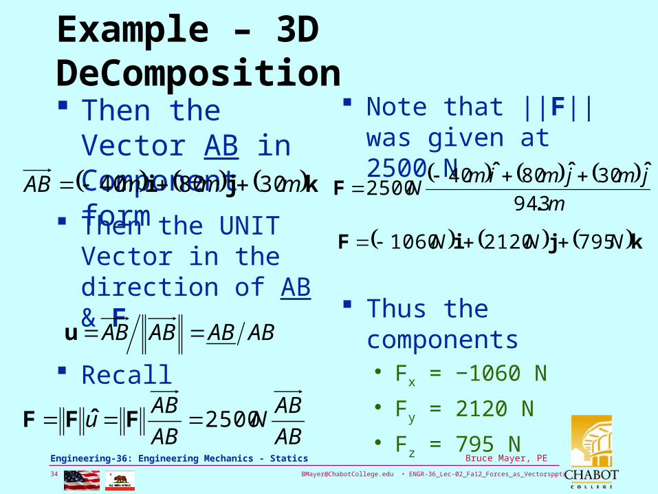
Example – 3D DeComposition
Then the Vector AB in Component form kji mmmAB 308040
Then the UNIT Vector in the direction of AB & F
ABABABAB u
Recall
AB
ABN
AB
ABu 2500 FˆFF
Note that ||F|| was given at 2500 N
m
jmjmimN
394
3080402500
.
ˆˆˆF
kjiF NNN 79521201060
Thus the components• Fx = −1060 N
• Fy = 2120 N
• Fz = 795 N

[email protected] • ENGR-36_Lec-02_Fa12_Forces_as_Vectorspptx35
Bruce Mayer, PE Engineering-36: Engineering Mechanics - Statics
Example – 3D DeComposition
Now Find the Force-Direction Space-Angles
Using Direction Cosines
Note that ||F|| was given at 2500 N
Using Component Values from Before
Fcos m
m
F
Using arccos find• θx = 115.1°
• θ y = 32.0°
• θ z = 71.5°
N
NN
NN
N
z
y
x
2500
795cos
2500
2120cos
2500
1060cos

[email protected] • ENGR-36_Lec-02_Fa12_Forces_as_Vectorspptx36
Bruce Mayer, PE Engineering-36: Engineering Mechanics - Statics
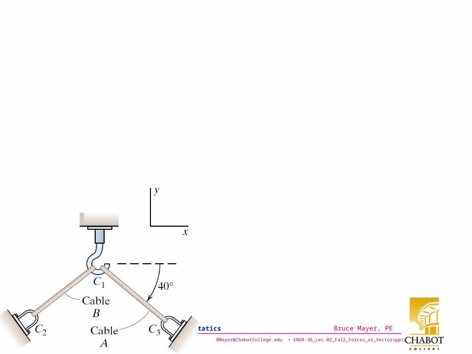
WhiteBoard Work
Lets WorkThis niceProblem
100
lbTA 500
lbTB 400
a. Express in Vector Notation the force that Cable-A exerts on the hook at C1
b. Express in Vector Notation the force that Cable-B exerts on the U-Bracket at C2

[email protected] • ENGR-36_Lec-02_Fa12_Forces_as_Vectorspptx37
Bruce Mayer, PE Engineering-36: Engineering Mechanics - Statics
wy wy
[email protected] • ENGR-36_Lec-02_Fa12_Forces_as_Vectorspptx38
Bruce Mayer, PE Engineering-36: Engineering Mechanics - Statics

[email protected] • ENGR-36_Lec-02_Fa12_Forces_as_Vectorspptx39
Bruce Mayer, PE Engineering-36: Engineering Mechanics - Statics
References
Good “Forces” WebPages• http://www.engin.brown.edu/courses/en3/N
otes/Statics/forces/forces.htm• http://www.pt.ntu.edu.tw/hmchai/Biomecha
nics/BMmeasure/StressMeasure.htm
Vectors• http://www.netcomuk.co.uk/~jenolive/
homevec.html

[email protected] • ENGR-36_Lec-02_Fa12_Forces_as_Vectorspptx40
Bruce Mayer, PE Engineering-36: Engineering Mechanics - Statics
Some Unit Vectors


