BLUEPRINTS & MAPS - Florida Rural Water · PDF fileBLUEPRINTS & MAPS FRWA 2016 ANNUAL...
43
BLUEPRINTS & MAPS FRWA 2016 ANNUAL CONFERENCE August 10, 2016 JASON D. SPARKS , P.E.
Transcript of BLUEPRINTS & MAPS - Florida Rural Water · PDF fileBLUEPRINTS & MAPS FRWA 2016 ANNUAL...

BLUEPRINTS
& MAPS
FRWA 2016 ANNUAL CONFERENCE
August 10, 2016
JASON D. SPARKS, P.E.

Weakness of attitude
becomes weakness of
character.
---- Albert Einstein


Recommended Standards for Water
Works or 10-State Standards
• Technical Resource incorporated into
FDEP Rules by reference
• Part 1.2 – PLANS
• 1.2.1 General Layout
– Title, Name of water supplier
– Area/Project to be served
– SCALE and North Arrow (Up or Right)
– Boundary Survey and datum used

Recommended Standards for
Water Works
– Date/Name/Address of design engineer
– PE Seal imprint
– LEGIBLE and reproducible
– Existing Utilities/Water Works
• Location, size, material, length
• Structures affecting impvmts. -- one sht.
• Part 1.2.2 -- Detailed Plans
– Water crossings inc. profiles and elevations
of stream bed, hi/lo H2O levels
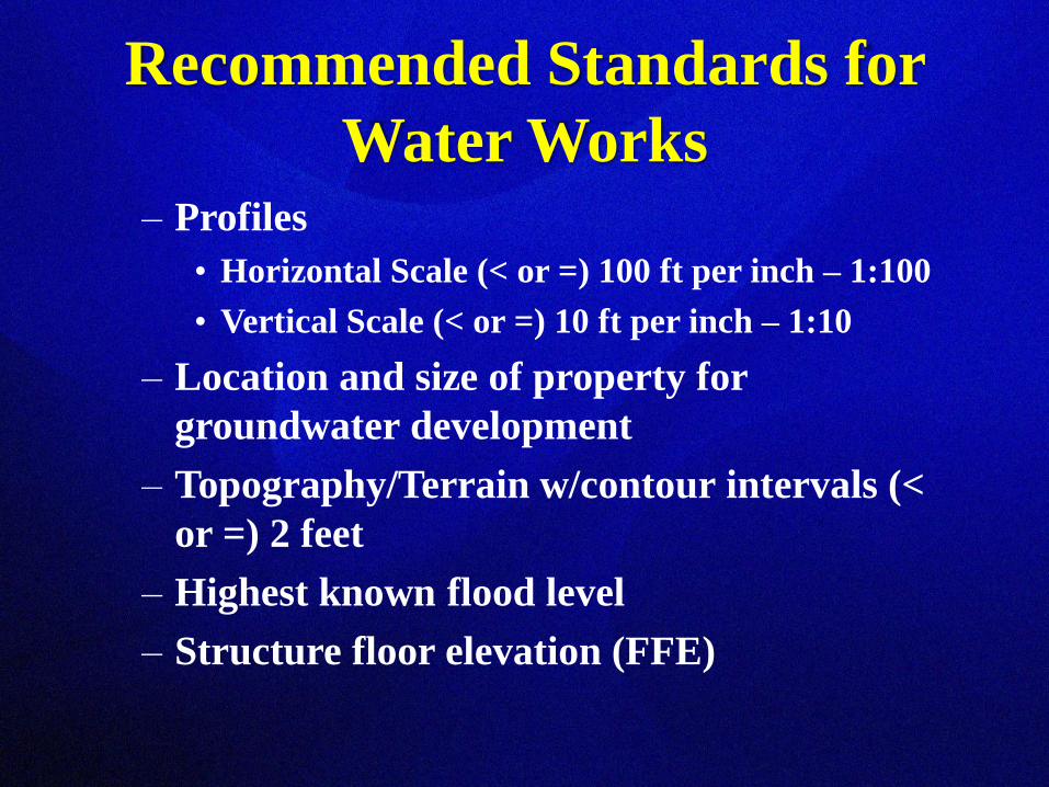
Recommended Standards for
Water Works– Profiles
• Horizontal Scale (< or =) 100 ft per inch – 1:100
• Vertical Scale (< or =) 10 ft per inch – 1:10
– Location and size of property for
groundwater development
– Topography/Terrain w/contour intervals (<
or =) 2 feet
– Highest known flood level
– Structure floor elevation (FFE)

Recommended Standards for
Water Works
– Upper terminal of protective casings &
ground surrounding
– Plan and profile drawings of improvements
• Pipelines
• Wells
• Drill hole diameter and depth
• Casing and liner diameter and depth
• Grouting depth
• Elevation and designation of natural geological
formations (Floridan, Avon, Hawthorn, etc.)

Recommended Standards for
Water Works
– Location of existing and potential pollution
– Existing and proposed:
• Streets
• Water sources
• Storm/Sanitary structures
• Combined & house sewers
• Septic Tanks
• Drainfields
• Cess Pools
– WTP process flow schematics/hydraulic
profile

Recommended Standards for
Water Works– Plant piping
– Chemical Storage Areas, feed eqpmt,
chemical application location(s)
– All improvement related
structures/discharges/disposal units
– Lavatories, showers, toilets, lockers (ADA)
– Proposed locations/dimensions/elevations
– Sample Tap Locations
– Any features not covered in specs.

Engineer Blueprint Checklist
A Cover Sheet including Project Location
Map with nearby and/or adjacent streets
labeled.
Cover sheet signed and sealed by engineer-
of-record.
A Drawing Index that clearly identifies the
names and sheet numbers of all drawings
under review, also on the Cover Sheet.
General/Specific Notes
Legend


Engineer Blueprint Checklist (cont’d)
The following information must appear
on all sheets:
– The design engineer's name
– The project name in lower right corner
– The phase to be constructed
A legible Utility Master Site Plan clearly
depicting utility infrastructure
The Utility Master Site Plan shall be a
maximum 1” = 40’ scale.
All phases of construction clearly shown

Engineer Blueprint Checklist (cont’d)
All plan sheets to scale with scale clearly
noted on each drawing.
All plan sheets shall have an arrow
indicating the direction north (pointing
up or to the right).
If the entire project area does not fit on
one sheet then print on multiple sheets.
A key map shall be provided on each
sheet indicating the location of the related
sheet within the project.

Engineer Blueprint Scale

Engineer Blueprint Scale

Engineer Blueprint Checklist
When multiple pages are used, a map of
the entire project area on a single
drawing, with limited labeling, shall be
included.
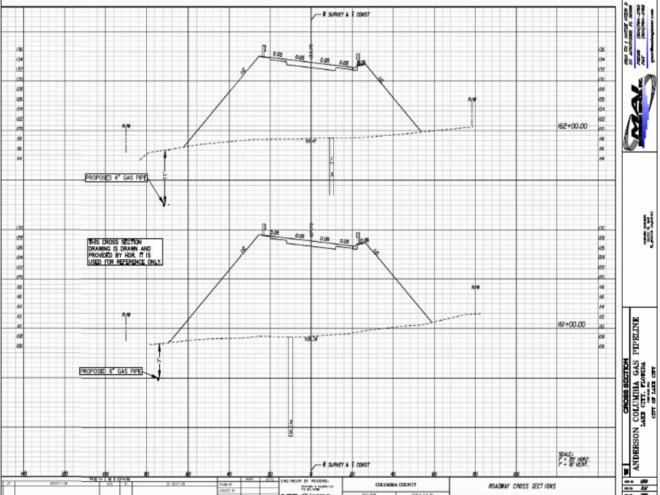
Mandatory Plan and Profile Sheets shall
be drawn at 1” = 20’ or 1” = 30’
(preferred) horizontal scale, and 1” = 2’
to 1” = 5’ vertical scale.
Building footprints

Engineer Blueprint Checklist (cont’d)
Each Plan and Profile Sheet shall display
the plan view above the profile view, and
each shall depict the same length of
utility installation. The plan shall be
aligned vertically with the profile.
The plan and profile sheet plan view
shall show the following:
Water mains, valves, fittings, fire hydrants
Services, meters, blow-offs


Engineer Blueprint Checklist (cont’d)
Wastewater mains, manholes, wyes, laterals,
cleanouts
Reclaimed water mains
Force mains
Stormwater lines and structures
Electric lines
Gas lines
Telco/FO/Conduit
Paving, curb and gutter
ROW, property lines
All existing and proposed features
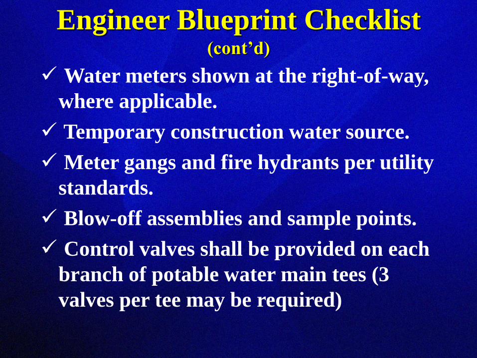
Engineer Blueprint Checklist (cont’d)
Water meters shown at the right-of-way,
where applicable.
Temporary construction water source.
Meter gangs and fire hydrants per utility
standards.
Blow-off assemblies and sample points.
Control valves shall be provided on each
branch of potable water main tees (3
valves per tee may be required)

Engineer Blueprint Checklist (cont’d)
Tap location and size
Required backflow preventers and types
Fire sprinkler lines
Clean-outs – top and invert elevations
MHs – top and invert elevations
Peak potable water demand w/ fire flow
Peak WW generation rate
WW Pump Station/Utility Standards
Utility specific construction std. details
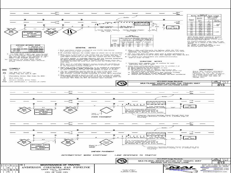
Landscape Plan, FDOT MOT Index


Engineer Blueprint Checklist (cont’d)
Sedimentation and Erosion Control
Dewatering


Mapping
• Not Surveying
• Spatial landbase
• GPS data collection
• Utility themes, feature classes and
attributes
• Effective cartographic design optimizes
communication of intended message
Map Evaluation
• Basics
– Author name
– Production date
– Title
– Sheet # (if in a series)

Map Evaluation
• Cartographic Requirement
– Purpose of map?
– Look and feel of map? (affective objective)
– Audience?
• Educational level
– Expected conditions for map use
• Medium, light, distance, etc.

Map Evaluation (cont’d)
• Cartographic compilation and design
– All themes and features included?
– Appropriate visual emphasis on imp.
theme(s)?
– Symbology for Q&Q data eff. applied?
• Colors/fonts/labels/graphics/images/text blocks
appropriate and legible?
– Map projection suited to purpose?
• Equal area, conformal, central meridian,
standard parallels, etc?

Map Evaluation (cont’d)
• Map elements and page layout
– Page look balanced?
– Do all map elements support objectives?
– Map elements logically placed?
– Map and elements aligned to page and each
other?
– Appropriate border?
– Orientation
• Is grid/graticule appropriately aligned and
labeled? Is north arrow required?

Map Evaluation (cont’d)
• Map elements and page layout
– Orientation
• Is grid/graticule appropriately aligned and
labeled?
• Is north arrow required?
– Scale
• Is scale appropriate?
• Bar appropriately designed, positioned and
sized?
• Units logical?

Map Evaluation (cont’d)
• Map elements and page layout
– Legend
• All necessary symbols and details included?
• Symbology exactly as appears on map?
• Logical structure to function of legend?
• Labels logical?
– Titles and Subtitles
• Relevant?
• Suitably descriptive (area mapped, date, subject,
etc.)?
• Suitably positioned and sized?

Map Evaluation (cont’d)
• Map elements and page layout
– Production notes
• Included?
• Dated correctly?
• Placed appropriately?
• Copyrighted sources correctly attributed?
• Map’s assertion to copyright included?
• Accuracy disclaimer?
• Attribution and/or revision details included?


QUESTIONS?
• Engineering Scale is a must have
• Always check scale on each sheet!!!
Jason D. Sparks, P.E.
Florida Rural Water Association
[email protected] or 850.668.2746