Blood Bank Management System (including UML diagrams)
14
Bachelor of Engineering Department of Information Technology A. D. Patel Institute of Technology Academic Year: 2013-14 [140703] Object Oriented Analysis Design with UML Blood Bank Management System Prepared by: Utsav Patel – 120010116017 – A5 Harshil Darji – 120010116045 – Divy Shah – 120010116055 – C5
-
Upload
harshil-darji -
Category
Engineering
-
view
3.409 -
download
43
description
This presentation is made by me & my two other friends on Blood Bank Management System with UML diagrams...
Transcript of Blood Bank Management System (including UML diagrams)
Bachelor of EngineeringDepartment of Information TechnologyA. D. Patel Institute of TechnologyAcademic Year: 2013-14
[140703]Object Oriented Analysis Design with UML
Blood Bank Management System
Prepared by:
Utsav Patel – 120010116017 – A5
Harshil Darji – 120010116045 – B5
Divy Shah – 120010116055 – C5
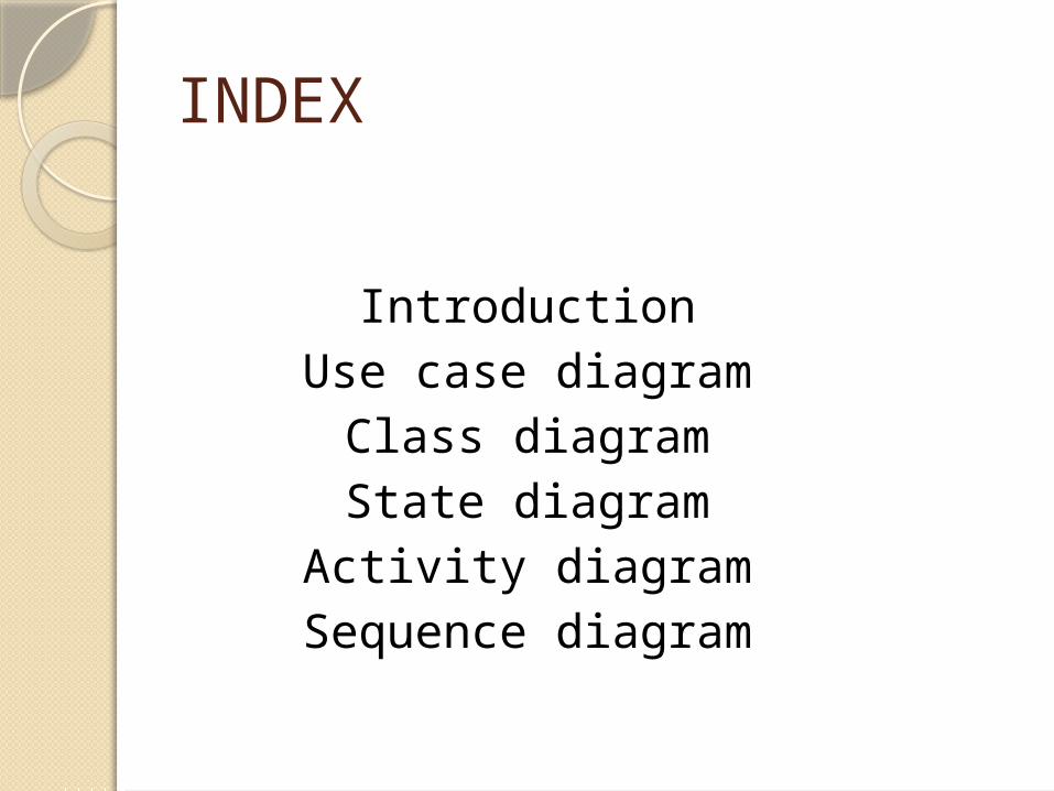
INDEX
IntroductionUse case diagram
Class diagramState diagram
Activity diagramSequence diagram

Introduction
The goal of blood management is to ensure the safe and efficient use of the many resources involved in the complex process of blood component therapy.
Our experience with comprehensive blood management programs has demonstrated sustainable reductions in the use of blood products by twenty percent or greater. This reduction reflects a more efficient utilization of blood and its associated resources, along with improvements in patient safety and the quality of care.

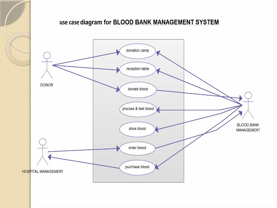
Use case diagramA use case diagram at its simplest is a representation of a user's interaction with the system.Cases included in following use-case diagram: Donation camp, Reception table, Donate blood, Process & test blood, Store blood, Order blood, purchase blood.

Class diagram
a class diagram in the UML is a type of static structure diagram that describes the structure of a system by showing the system's classes, their attributes, operations (or methods), and the relationships among objects.Classes included in following diagram: Donor, Receptionist, Doctor, Nurse, Lab technician, Blood, Blood bank, Hospital.


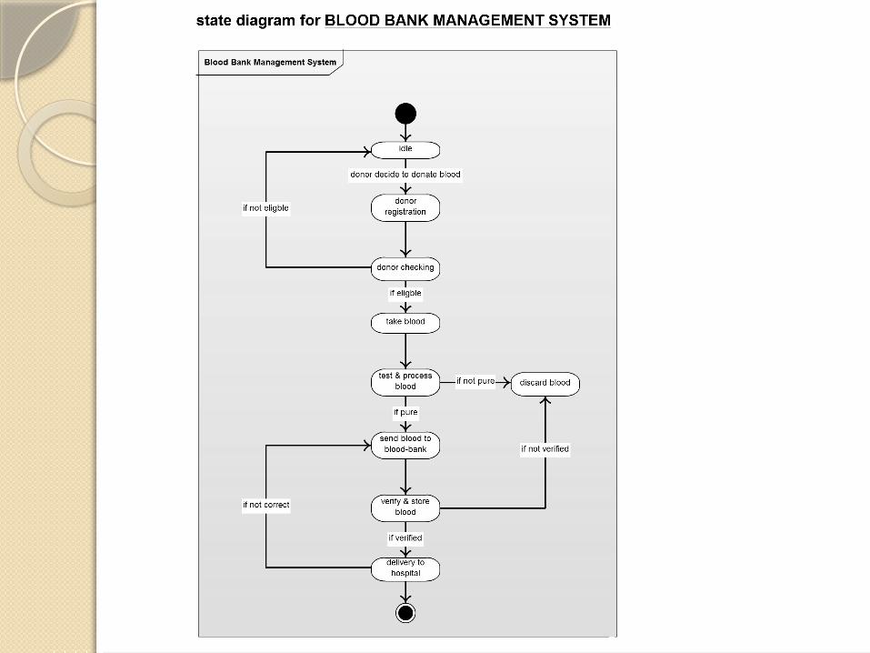
State diagramA state diagram is a type of diagram used in computer science and related fields to describe the behavior of systems. State diagrams require that the system described is composed of a finite number of states.
States included in following system:Idle, Donor registration, Donor checking, Take blood, Test and process blood, Send blood to blood bank, Verify and store blood, Delivery to hospital.

Activity diagramActivity diagrams are graphical representations of workflows of stepwise activities and actions with support for choice, iteration and concurrency.
the process of activity diagram is same as state diagram, there are mainly two differences; first: in this diagram condition is checked using rectangle,second: synchronized bar which use to split and merge activities/state of diagram.


Sequence diagramA sequence diagram is an interaction diagram that shows how processes operate with one another and in what order. It is a construct of a Message Sequence Chart.
A sequence diagram shows, as parallel vertical lines (lifelines), different processes or objects that live simultaneously, and, as horizontal arrows, the messages exchanged between them, in the order in which they occur.
This allows the specification of simple runtime scenarios in a graphical manner.


. . . T H A N K Y O U . . .