Blindsight: Proximity Sensing and Wireless Haptic Feedback
87
Blindsight: Proximity Sensing and Wireless Haptic Feedback A Major Qualifying Project Submitted to the Faculty of the WORCESTER POLYTECHNIC INSTITUTE in partial fulfillment of the requirements for the Degree in Bachelor of Science by Aatreya Chakravarti Alan Fernandez Yeggi Lee Date of Submission: April 24, 2019 Professor Stephen Bitar, Major Advisor Dr. Yitzhak Mendelson, Co-Advisor
Transcript of Blindsight: Proximity Sensing and Wireless Haptic Feedback

Blindsight: Proximity Sensing andWireless Haptic Feedback
A Major Qualifying Project
Submitted to the Faculty
of the
WORCESTER POLYTECHNIC INSTITUTE
in partial fulfillment of the requirements for the
Degree in Bachelor of Science
by
Aatreya Chakravarti
Alan Fernandez
Yeggi Lee
Date of Submission: April 24, 2019
Professor Stephen Bitar, Major Advisor
Dr. Yitzhak Mendelson, Co-Advisor

Worcester Polytechnic Institute
Advisor: Professor Stephen Bitar
Co-Advisor: Dr. Yitzhak Mendelson
Blindsight Assistive Technology
Author:Aatreya ChakravartiAlan FernandezYeggi Lee
Major:ECE\BME
ECEECE
April 24, 2019
Abstract
A staggering 98 percent of blind people have experienced head-level accidents with somerequiring professional medical assistance. Current technologies such as the white cane andguide dogs come with a significant flaw: the inability to detect objects at head-level. As such,the objective of this project was to create a more effective and affordable means to detectand prevent head-level injuries in blind people. Blindsight uses ultrasonic sensors to detectobstacles and transmits this information to haptic vibration motors which will then alert theuser of incoming obstacles.

Acknowledgements
The completion of our project would not have been accomplished without the sponsorship ofthe New England Center for Analog and Mixed Signal Integrated Circuit Design (NECAM-SID) lab.
We would also like to thank Sharon Strzalkowski and the Commission of the Blind for theiraid during the testing phase. The feedback received was beneficial towards making betterprototypes.
Additionally, we would also like to extend our sincerest thanks to our Major QualifyingProject advisors, Professor Stephen Bitar and Professor Yitzhak Mendelson for their con-stant support, patience, and guidance throughout the duration of this project.

Executive Summary
According to the World Health Organization, there are approximately 1.3 billion peoplearound the world living with some form of vision impairment. Out of these 1.3 billion, about217 million have moderate to severe vision impairment and 36 million people are entirelyblind (Blindness Statistics , 2018). The number of people with legal blindness is only ex-pected to increase as the population ages. Any significant loss of sight is life-altering assignificant adjustments must be made in order to maintain the same level of mobility. Dailyactivities and tasks such as cooking and navigating in tight spaces, can become extremelychallenging and potentially dangerous (Visual Impairment , 2016).
As such, there has been a greater demand for assistive devices for navigation and orien-tation. The most common navigation tools used today are the guide dog and the white cane.However, these tools come with a significant flaw: the inability to consistently detect objectsabove the waist. According to a study done in the University of Santa Cruz, 98 percentof blind respondents have experienced head-level accidents with some requiring professionalmedical assistance (Manduchi & Kurniawan, 2011). About 26 percent of the time, this causedthe respondent to doubt their ability to travel alone. Already, innovations such as the SunuBand and the Ultracane have become available to the public to help with this issue; however,these products are often times not affordable for a blind user (Manduchi & Kurniawan, 2011).
To combat this issue, our team developed a device that aims to aid blind individuals indetecting head-level objects. The system comprises of a sensing module in the form of a pairof glasses and two haptic feedback modules in the form of wristbands. The glasses collectproximity data from the environment and transmit this data wirelessly to the bands. Thebands then pulse at different intensities to alert the user of any head-level objects in theirpath.
The seven principles of universal design were applied to create a system that tended tothe needs of a wide customer base within the blind community. This was done by first re-searching assistive technology and blindness, defining customer needs and design constraints,reviewing previous research, and assessing prior art. Next, value analyses were carried outin order to assess and determine which components to include. Factors such as performance,affordability, reliability, ease of use, and design were taken into account when judging differ-ent components.

Blindsight Assistive Technology
The chosen components were then used in order to create both the glasses, which includedthe sensors, and the haptic feedback bands, which included the vibrating motors. Wirelesscommunication was established between the glasses and the bands and power consumptionwas determined under continuous transmission and vibration conditions. Later on, the teambegan prototyping on a circuit board with which initial component verification and func-tional testing was conducted. Once the components were better understood, the design wasreevaluated, and unnecessary parts were eliminated.
Communication between the microcontroller and the bands was then established and tested.The initial prototype was finished within the first few weeks of January. Following this, theteam met with Sharon Strzalkowski, the Regional Director of the Worcester Commission ofthe Blind, to test the prototype and receive feedback. Using the feedback received from themeeting, modifications were made in the design and a PCB was created in order to fit all ofthe components into a sleek, compact design.
Further testing was carried out on individuals with no visual impairment. These individ-uals were asked to walk through a course with obstacles that were meant to simulate thedangers present in common environments that might cause head-level accidents to occur.The feedback received was informative in multiple areas. Firstly, it was clear that there arechallenges in effectively communicating information through vibrations. More specifically, atrade-off exists between the periodicity of vibrations and the intensity of vibrations. Anotherarea of weakness that was identified through feedback was the characteristics of the ultrasonicsensor that was used. Participants complained about a narrow field-of-view and as designerswe also noticed the effects of an inadequately low sampling rate on the speed with which thepresence of obstacles was detected.
Although the device that was produced at the end of this project was not perfect, themost important takeaway from this experience was the importance of using a design centricapproach in the development of disability aids. It was noticed that disability aids tend tosacrifice aesthetics and functional design in order to tackle the problem. Even though theresulting device may solve the problem for which it was designed, the device will most likelysuffer from low adoption rates and high abandonment rates. This is the result of the stigmaattached to disability aids that stand out and have no aesthetic attractive to make the userproud of wearing the device rather than ashamed. It is then crucial to have the Seven Princi-ples of Universal Design at the core of the development of the device rather than to develop adevice first and then attempt to adapt it to meet these principles. Blindsight was developed

Blindsight Assistive Technology
in this manner, with a very clear design philosophy and constraints pandering to the needs ofblind individuals from the start of the project. Wireless communication, wireless charging,modular design, improved sensors and a sleek casing were the result of this design centricapproach and these are some of the features that distinguish Blindsight from other productson the market.

Blindsight Assistive Technology
Contents
1 Literature Review 11.1 Introduction . . . . . . . . . . . . . . . . . . . . . . . . . . . . . . . . . . . . 11.2 Problem Statement . . . . . . . . . . . . . . . . . . . . . . . . . . . . . . . . 21.3 Competing Products . . . . . . . . . . . . . . . . . . . . . . . . . . . . . . . 2
1.3.1 Prior Art . . . . . . . . . . . . . . . . . . . . . . . . . . . . . . . . . 21.3.2 Competitive Value Analysis . . . . . . . . . . . . . . . . . . . . . . . 9
1.4 Complementary Products . . . . . . . . . . . . . . . . . . . . . . . . . . . . 121.4.1 The Long Cane . . . . . . . . . . . . . . . . . . . . . . . . . . . . . . 121.4.2 Navigation with Guide Dogs . . . . . . . . . . . . . . . . . . . . . . . 14
1.5 Difficulties with Everyday Technologies . . . . . . . . . . . . . . . . . . . . . 151.5.1 Flaws in Traditional Devices . . . . . . . . . . . . . . . . . . . . . . . 16
2 Project Strategy 172.1 Design Approach . . . . . . . . . . . . . . . . . . . . . . . . . . . . . . . . . 17
2.1.1 Seven Principles of Universal Design . . . . . . . . . . . . . . . . . . 172.1.2 Iterative Design Process . . . . . . . . . . . . . . . . . . . . . . . . . 17
2.2 Introduction to BAT . . . . . . . . . . . . . . . . . . . . . . . . . . . . . . . 182.2.1 Purpose . . . . . . . . . . . . . . . . . . . . . . . . . . . . . . . . . . 182.2.2 High-Level Systems Perspective . . . . . . . . . . . . . . . . . . . . . 192.2.3 Design Constraints . . . . . . . . . . . . . . . . . . . . . . . . . . . . 192.2.4 Decision Matrix . . . . . . . . . . . . . . . . . . . . . . . . . . . . . . 222.2.5 Weight Assesment . . . . . . . . . . . . . . . . . . . . . . . . . . . . 23
2.3 Specific Module Design Options . . . . . . . . . . . . . . . . . . . . . . . . . 242.3.1 Sensor . . . . . . . . . . . . . . . . . . . . . . . . . . . . . . . . . . . 252.3.2 Haptic Feedback Actuator . . . . . . . . . . . . . . . . . . . . . . . . 27
2.4 Microcontroller . . . . . . . . . . . . . . . . . . . . . . . . . . . . . . . . . . 292.5 Battery . . . . . . . . . . . . . . . . . . . . . . . . . . . . . . . . . . . . . . 312.6 Power Management Integrated Circuit . . . . . . . . . . . . . . . . . . . . . 332.7 Gantt Chart . . . . . . . . . . . . . . . . . . . . . . . . . . . . . . . . . . . . 34
3 Product Development 363.1 Sensor Module Integration . . . . . . . . . . . . . . . . . . . . . . . . . . . . 36
3.1.1 Sensor Testing . . . . . . . . . . . . . . . . . . . . . . . . . . . . . . . 363.2 Motor Module Integration . . . . . . . . . . . . . . . . . . . . . . . . . . . . 403.3 Temperature Sensor Integration . . . . . . . . . . . . . . . . . . . . . . . . . 42
I

Blindsight Assistive Technology
3.4 Communication Module Integration . . . . . . . . . . . . . . . . . . . . . . . 423.5 Evolution of Device Casing . . . . . . . . . . . . . . . . . . . . . . . . . . . . 44
4 Systems Level Device Description 484.1 Hardware Architecture . . . . . . . . . . . . . . . . . . . . . . . . . . . . . . 484.2 Software Architecture . . . . . . . . . . . . . . . . . . . . . . . . . . . . . . . 50
4.2.1 High Level Software Overview . . . . . . . . . . . . . . . . . . . . . . 504.2.2 Sensing . . . . . . . . . . . . . . . . . . . . . . . . . . . . . . . . . . 504.2.3 Pause . . . . . . . . . . . . . . . . . . . . . . . . . . . . . . . . . . . 504.2.4 Sensitivity Adjustment . . . . . . . . . . . . . . . . . . . . . . . . . . 534.2.5 Intensity Adjustment . . . . . . . . . . . . . . . . . . . . . . . . . . . 534.2.6 Communication . . . . . . . . . . . . . . . . . . . . . . . . . . . . . . 544.2.7 Calibration . . . . . . . . . . . . . . . . . . . . . . . . . . . . . . . . 554.2.8 Haptic Feedback . . . . . . . . . . . . . . . . . . . . . . . . . . . . . 56
4.3 Casing . . . . . . . . . . . . . . . . . . . . . . . . . . . . . . . . . . . . . . . 57
5 Device Testing and Results 595.1 Testing with Device Designers . . . . . . . . . . . . . . . . . . . . . . . . . . 605.2 Testing with Individuals Without Visual Impairments . . . . . . . . . . . . . 605.3 Testing with Individuals With Visual Impairments . . . . . . . . . . . . . . . 61
6 Conclusion and Recommendations 626.1 Recommendations . . . . . . . . . . . . . . . . . . . . . . . . . . . . . . . . . 62
6.1.1 Processor and Sensing . . . . . . . . . . . . . . . . . . . . . . . . . . 626.1.2 Frame Design . . . . . . . . . . . . . . . . . . . . . . . . . . . . . . . 626.1.3 Alternative Form Factors . . . . . . . . . . . . . . . . . . . . . . . . . 62
6.2 Conclusion . . . . . . . . . . . . . . . . . . . . . . . . . . . . . . . . . . . . . 63
References 64
Appendix 68A Sensor Testing Data . . . . . . . . . . . . . . . . . . . . . . . . . . . . . . . 68B Feedback Forms for Testing with Sighted Individuals . . . . . . . . . . . . . 73C Cost of Components . . . . . . . . . . . . . . . . . . . . . . . . . . . . . . . 75
II

Blindsight Assistive Technology
List of Figures
1 Object detection sensor goggles image filed with patent . . . . . . . . . . . . 32 Software algorithm flow diagram image filed with patent . . . . . . . . . . . 33 Ultracane image filed with patent . . . . . . . . . . . . . . . . . . . . . . . . 44 Software obstacle avoidance algorithm flow chart . . . . . . . . . . . . . . . . 55 Sensory Substitution device image filed with patent . . . . . . . . . . . . . . 56 High frequency goggle object detection device image filed with patent . . . . 67 ETA device image filed with patent . . . . . . . . . . . . . . . . . . . . . . . 68 BLAID image filed with patent . . . . . . . . . . . . . . . . . . . . . . . . . 79 ETA device image filed with patent . . . . . . . . . . . . . . . . . . . . . . . 810 Artist rendition of quadcopter with monovision sensor mounted on front . . 811 Sunu Band . . . . . . . . . . . . . . . . . . . . . . . . . . . . . . . . . . . . . 1012 BuzzClip . . . . . . . . . . . . . . . . . . . . . . . . . . . . . . . . . . . . . . 1013 UltraCane . . . . . . . . . . . . . . . . . . . . . . . . . . . . . . . . . . . . . 1114 iGlasses . . . . . . . . . . . . . . . . . . . . . . . . . . . . . . . . . . . . . . 1215 Tom Pouce Electronic Canes . . . . . . . . . . . . . . . . . . . . . . . . . . . 1216 Visual demonstration of the relationship between number of iterations and the
usability of the product . . . . . . . . . . . . . . . . . . . . . . . . . . . . . . 1817 High-Level Block Diagram of the BAT . . . . . . . . . . . . . . . . . . . . . 1918 Visual demonstrating the specific approach followed in the design of the BAT
in chronological order . . . . . . . . . . . . . . . . . . . . . . . . . . . . . . . 3419 Gantt Chart representing the timeline of our project . . . . . . . . . . . . . 3520 Testing MB1020 Ultrasonic sensors outdoors in an open driveway . . . . . . 3621 Standalone circuit used to test the VL53L0X Infrared Sensor . . . . . . . . . 3722 Expected calibration graph given in the VL53L0X datasheet . . . . . . . . . 3723 Standalone circuit used to test the MB1020 Ultrasonic Sensor . . . . . . . . 3824 Sensor Distance Readings Overlapping . . . . . . . . . . . . . . . . . . . . . 3925 Standalone circuit used to test the ST Vibrating motor . . . . . . . . . . . . 4026 Motor current characteristics acquired by measuring the potential across the
1ohm base resistor . . . . . . . . . . . . . . . . . . . . . . . . . . . . . . . . 4127 Standalone circuit used to test the TMP3602 Temperature sensor . . . . . . 4228 Standalone circuit used to test the NRF24L01 Wireless transceiver . . . . . . 4229 Standalone circuit used to test the NRF24L01 Wireless transceiver along with
a single sensor . . . . . . . . . . . . . . . . . . . . . . . . . . . . . . . . . . . 4330 Oscilloscope image of original waveform . . . . . . . . . . . . . . . . . . . . . 44
III

Blindsight Assistive Technology
31 Oscilloscope image of waveform after correcting the code . . . . . . . . . . . 4432 Top view of first iteration of casing . . . . . . . . . . . . . . . . . . . . . . . 4533 Front view of first iteration of casing . . . . . . . . . . . . . . . . . . . . . . 4534 Front angled view of second iteration of casing . . . . . . . . . . . . . . . . . 4635 Isometric view of second iteration of casing . . . . . . . . . . . . . . . . . . . 4636 Isometric view of third iteration of casing . . . . . . . . . . . . . . . . . . . . 4737 Final glasses system circuit . . . . . . . . . . . . . . . . . . . . . . . . . . . . 4838 Final band system circuit . . . . . . . . . . . . . . . . . . . . . . . . . . . . 4939 From top to bottom (a) Board containing MCU and Communication Module
(b) Board containing user adjustable features . . . . . . . . . . . . . . . . . 4940 Board containing MCU, Communication Module and Motor Driver Circuit . 5041 Visual representation of how our code flows through different functions and
states . . . . . . . . . . . . . . . . . . . . . . . . . . . . . . . . . . . . . . . 5142 Isometric View of Glasses . . . . . . . . . . . . . . . . . . . . . . . . . . . . 5843 Isometric View of Wireless Charging Pad . . . . . . . . . . . . . . . . . . . . 5844 Isometric View of Glasses and the Bands placed on the Wireless Charging Pad 5845 From left to right (a) Overextended window sill (b) Overhanging support struc-
ture (c) Stop sign . . . . . . . . . . . . . . . . . . . . . . . . . . . . . . . . . 5946 From left to right (a) Sighted individuals participating in course and approach-
ing an overhanging support structure obstacle (b) Sighted individual wearingBAT device . . . . . . . . . . . . . . . . . . . . . . . . . . . . . . . . . . . . 60
47 Comparing round 1 indoors VL53L0X sensor data linear regression line to theline of identity . . . . . . . . . . . . . . . . . . . . . . . . . . . . . . . . . . . 68
48 Comparing round 2 indoors VL53L0X sensor data linear regression line to theline of identity . . . . . . . . . . . . . . . . . . . . . . . . . . . . . . . . . . . 69
49 Comparing round 3 indoors VL53L0X sensor data linear regression line to theline of identity . . . . . . . . . . . . . . . . . . . . . . . . . . . . . . . . . . . 70
50 Comparing round 1 outdoors VL53L0X sensor data linear regression line tothe line of identity . . . . . . . . . . . . . . . . . . . . . . . . . . . . . . . . 71
51 Comparing round 1 indoors MB1020 sensor data linear regression line to theline of identity . . . . . . . . . . . . . . . . . . . . . . . . . . . . . . . . . . . 72
52 Comparing round 1 outdoors MB1020 sensor data linear regression line to theline of identity . . . . . . . . . . . . . . . . . . . . . . . . . . . . . . . . . . . 72
IV

Blindsight Assistive Technology
List of Tables
1 Value Analysis for Competing Products . . . . . . . . . . . . . . . . . . . . . 92 Decision Matrix for Rank Ordering of Design Goals . . . . . . . . . . . . . . 223 Value Analysis for Sensor . . . . . . . . . . . . . . . . . . . . . . . . . . . . . 254 Value Analysis for Haptic Feedback Actuator . . . . . . . . . . . . . . . . . . 275 Value Analysis for Microcontroller . . . . . . . . . . . . . . . . . . . . . . . . 296 Value Analysis for Battery . . . . . . . . . . . . . . . . . . . . . . . . . . . . 317 Value Analysis for Power Management IC . . . . . . . . . . . . . . . . . . . 338 Round 1 VL53L0X Sensor Data Indoors . . . . . . . . . . . . . . . . . . . . 689 Round 2 VL53L0X Sensor Data Indoors . . . . . . . . . . . . . . . . . . . . 6910 Round 3 VL53L0X Sensor Data Indoors . . . . . . . . . . . . . . . . . . . . 6911 Round 1 VL53L0X Sensor Data Outdoors . . . . . . . . . . . . . . . . . . . 7012 Round 1 MB1020 Sensor Data Indoors . . . . . . . . . . . . . . . . . . . . . 7113 Round 1 MB1020 Sensor Data Outdoors . . . . . . . . . . . . . . . . . . . . 7214 Component List . . . . . . . . . . . . . . . . . . . . . . . . . . . . . . . . . . 75
V

Blindsight Assistive Technology
1 Literature Review
1.1 Introduction
There are more than 25.5 million people living with some sort of vision impairment in theUnited States with 1.1 million being completely blind (Blindness Statistics , 2018). Thesenumbers are only expected to rise as the population ages. In fact, according to the NationalEye Institute, the number of people with legal blindness will increase by 21 percent eachdecade reaching a staggering 2 million by 2050 (Visual Impairment , 2016).
Any significant loss of sight is traumatic and life-altering affecting not only the quality of life,but also the probability of accidental injury. Routine tasks and daily activities that mostof us take for granted, such as crossing the road, cooking, or navigating in tight spaces, canbecome extremely challenging and overwhelming for someone trying to navigate using onlyfour out of five senses.
As such, the need for assistive devices for navigation and orientation has increased. Themost common and affordable navigation tools used today are guide dogs and the white cane.Despite their popularity, they cannot provide all the information needed for safe mobilitysince the cane does not detect anything above the waist and the guide dog is concentratedmostly on objects at its own height. According to a study done in the University of SantaCruz, 98 percent of blind respondents have experience head-level accidents with 23 percentof accidents requiring professional medical assistance. After these incidents, in 26 percentof the cases, the head-level accident affected the respondent’s confidence as an independenttraveller (Manduchi & Kurniawan, 2011).
To combat this issue, this project applies the principles of universal design to develop adevice that seamlessly integrates into the life of the individual, while solving the clear pathproblem. The Blindsight Assistive Technology uses ultrasonic sensors integrated into theframe of the glasses to detect obstacles above the waist level. The presence of obstacleswithin the Field of View (FOV) is communicated via two or more vibrating motors. Thesimple, attractive, and inclusive design allows for the device to be easily adopted by visuallyimpaired individuals regardless of age, gender and level of dexterity.
1

Blindsight Assistive Technology
1.2 Problem Statement
The most popular assistive technologies, the white cane and the guide dog, do not offer anyform of consistent feedback regarding the presence of obstacles above the waist level. Exist-ing solutions to the problem tend to disregard the principles of universal and aestheticallypleasing design leading to low device adoption rates and device abandonment. The challengeis to design a device that is capable of solving the clear path problem, seamlessly integrateinto the individual’s life, and accommodate for any level of dexterity.
1.3 Competing Products
Since the 1970s, many groups have designed devices aimed at improving the quality of lifeof blind individuals with mixed success. Understanding the successes and failures of theseproducts is crucial to developing a product capable of competing in the current assistivedevice market. Therefore, a brief history of the development of blind assistive device is givenbelow such that the reader can become familiar with how the technology started and whereit is today. The devices described were obtained exclusively from patents and are listed in achronological manner.
1.3.1 Prior Art
• Highly Relevant: Patents that are in direct conflict with the idea of the Blindsightdevice.
• Relevant: Patents that have some relevance to the project, but are not in direct conflictwith it.
• Irrelevant: Patents that are listed because they form part of a group of patents filed tocomplement a highly relevant patent but may hold little value for the project.
Obstacle Detection System Using Sensors on Goggles (1972):This patent, one of the first filed for a wearable blind assistive device technology, was ap-proved in 1972 and has since expired. In this patent, the inventor describes the use of lightbased time-of-flight ranging sensors to detect obstacles in the path of the user. These sensorsare mounted on a pair of goggles behind the lens (Benjamin, 1970).
The main takeaway from this patent is the form factor that is functionally efficient whilesimultaneously being aesthetically pleasing. However, there are some negative aspects of thisdesign including the location of the battery pack that runs a wire to the glasses to power the
2

Blindsight Assistive Technology
device. In any potential device resulting from this report, the power system will be locatedon the device itself rather than in a separate unit connected by a wire.
Figure 1: Object detection sensor goggles image filed with patent
Systems and methods providing tactile guidance using sensory supplementation:This patent describes a device that uses a vibrating actuator to guide a user to a desireddestination through GPS. The use of vibrational cues allows the user to concentrate on thevisual and auditory feedback rather than to focus on a device to follow directions. Thispatent simply describes a method for waypoint finding, not a device for obstacle avoidance.However, the use of tactile feedback rather than auditory feedback for directional cues isa notable characteristic that will be incorporated into the device resulting from this paper(Sokoler, Nelson, & Pedersen, 1999).
Figure 2: Software algorithm flow diagram image filed with patent
Ultracane Patent:This patent was filed by Sound Foresight, the company that produced the Ultracane, how-ever, the description of the device found in the patent document and the description foundon the Ultracane product website differ greatly. The most likely reason for this discrepancyis that the patent was filed at a very early stage of development for this device and therefore
3

Blindsight Assistive Technology
the final product design varied greatly while the technology that was patented remained thesame (Withington, Waters, Povey, & Hoyle, 1998).
The Ultracane is a device that that includes a number of ultrasonic ranging sensors thatprovide the user with increased spatial awareness through tactile feedback. From a systemslevel perspective, a potential device developed as a part of this paper would also use a rangingsensor and provide proximity information through haptic feedback. One of the disadvantagesof the ultracane is the location of the sensor below the hip which might decrease the device’sfield of view. Another drawback related to the location of the device is the motion artifactwhich is ever present due to the placement of the device on the cane which is constantlymoved by blind individuals. This continuous motion might cause the proximity informationto be more inaccurate than if the sensor were attached to a more stationary part of the body(e.g. head, torso etc.).
Figure 3: Ultracane image filed with patent
UAV Obstacle Detection and Avoidance (Stereovision):This patent describes the use of a stereovision setup to capture images that will then be sam-pled to obtain a 3D representation of the space. The distance between the points in the spaceand the drone is calculated based on the latency between transmitted and received signals.The trajectory of the obstacles is predicted in order to execute corrective actions. The ad-vantages of this device is the accuracy of the sensor module and the detailed 3D informationgathered by the device. However, the haptic feedback module required to communicate thisdetailed 3D information to the user would have to be equally complicated which would not
4

Blindsight Assistive Technology
only hinder the intuitive design this paper is aiming for but would also increase cost, powerconsumption and size as a result (Nichani, 1999).
Figure 4: Software obstacle avoidance algorithm flow chart
Sensory Substitution Through Vibrating Actuators:This patent describes a sensory substitution device that captures depth and color informa-tion about the environment. This information is relayed to the user via vibrating actuators.In respect to our project, the characteristic of this device that is of most interest is thehaptic feedback module which transmits depth information via intensity and color informa-tion via frequency. The patent does not cover how this information is collected. Rather, itfocuses on the signal processing aspect once the information has been received (Ward, 2005).
Figure 5: Sensory Substitution device image filed with patent
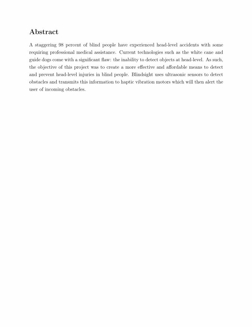
Object Detection System Using Sensors on Goggles with Gigahertz Waves:This patent describes a pair of goggles that achieve obstacle detection using a 94GHz wavetransceiver very similar to the sensor technology that will be utilized in a potential device
5
Blindsight Assistive Technology
resulting from this paper. Despite the accuracy of the sensor module and the apt location ofthe device, there are many drawbacks to this product. For one, the obstacle information isrelayed to the user via audible signals which would interfere with the blind individuals abilityto listen to feedback from their surroundings. Additionally, the 3x7 tactile matrix displayedin the figure would result in complex vibrational cues that might prove to be less effectivethan simple vibrational feedback (Jung, Chae, & Rhee, 2006).
Figure 6: High frequency goggle object detection device image filed with patent
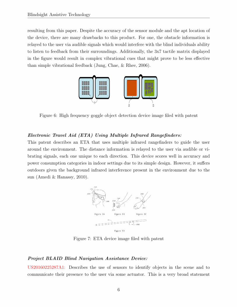
Electronic Travel Aid (ETA) Using Multiple Infrared Rangefinders:This patent describes an ETA that uses multiple infrared rangefinders to guide the useraround the environment. The distance information is relayed to the user via audible or vi-brating signals, each one unique to each direction. This device scores well in accuracy andpower consumption categories in indoor settings due to its simple design. However, it suffersoutdoors given the background infrared interference present in the environment due to thesun (Amedi & Hanassy, 2010).
Figure 7: ETA device image filed with patent
Project BLAID Blind Navigation Assistance Device:
US20160225287A1: Describes the use of sensors to identify objects in the scene and tocommunicate their presence to the user via some actuator. This is a very broad statement
6

Blindsight Assistive Technology
that seems to encompass the entirety of time-of-flight assistive device that communicate viahaptic feedback (Djugash, 2015).
US20160225286A1: A navigation aid that uses a number of cameras and image processing toidentify objects in the scene. Information about the object is relayed to the user via sound(Dayal, Chen, & Thackston, 2016).
US20180012377A1: Describes another calibration method of the camera (?, ?).
US20170367921A1: Describes the method of correcting the image captured by the camerawith inertial sensor. This negative feedback corrects image tilt in order to properly processthe scene for object recognition (Matsuno, 2016).
US20180012376A1: Describes a method for aligning the cameras with the physical charac-teristics of the user. This is something to take into consideration in designing the a potentialdevice for this paper given that a general configuration may not fit all users (Dayal et al.,2016).
The BLAID device using a conjunction of sensors and cameras to provide a 3D visualizationof the environment. Despite the impressive engineering behind such a complex product, theBLAID device tries to do too much in a single unit. The device integrates AI image process-ing, advanced sensor obstacle avoidance, tactile feedback as well as auditory feedback. Allthese different characteristics can make the use of this device difficult and non-intuitive.
Figure 8: BLAID image filed with patent
Electronic Travel Aid on a Necklace:This patent describes an electronic travel assistance device that is worn around the neck.The necklace includes vibrating actuators that will communicate the presence of objects asdetected by the imaging sensors. The vibrations are felt on the neck of the user as shown in
7
Blindsight Assistive Technology
the figure. The location and simplicity of the haptic feedback module are attractive features.However, the location and vulnerability to movement when walking are characteristics thatwill not be mimicked for any potential product developed (Mahoney, 2009).
Figure 9: ETA device image filed with patent
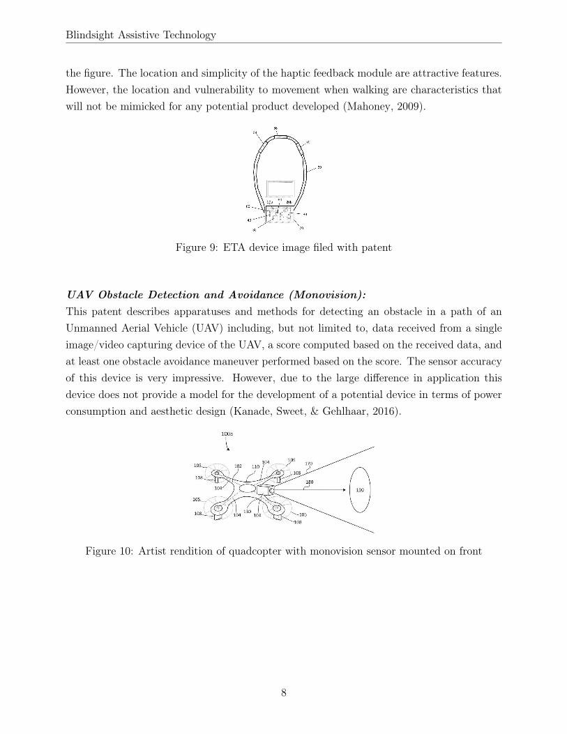
UAV Obstacle Detection and Avoidance (Monovision):This patent describes apparatuses and methods for detecting an obstacle in a path of anUnmanned Aerial Vehicle (UAV) including, but not limited to, data received from a singleimage/video capturing device of the UAV, a score computed based on the received data, andat least one obstacle avoidance maneuver performed based on the score. The sensor accuracyof this device is very impressive. However, due to the large difference in application thisdevice does not provide a model for the development of a potential device in terms of powerconsumption and aesthetic design (Kanade, Sweet, & Gehlhaar, 2016).
Figure 10: Artist rendition of quadcopter with monovision sensor mounted on front
8

Blindsight Assistive Technology
1.3.2 Competitive Value Analysis
Table 1: Value Analysis for Competing Products
As of now, few products with similar goals are offered in the market. We chose five competi-tors who had similar goals to ours in order to fully understand what appealed to the market.These included the Sunu Band, BuzzClip, UltraCane, iGlasses, and Tom Pouce. All of theseproducts aimed to improve the quality of life of blind individuals by providing a means forself-navigation that would prevent possible injuries. The main differences of these productswere the design as some took the shape of a clip while others took on more traditional shapeslike a cane.
To further evaluate our competition, the customer’s essential criteria was divided into re-liability, design, ease of use, performance, and affordability. A brief explanation of each isshown below. Each of these categories were rated from a scale of 1-10. Additionally, a smalldescription of each product is included.
• Reliability: Accuracy, Response time
• Design: Durability, Acceptable aesthetic design, Modularity
• Ease of Use: Intuitive to use, Comfort
• Performance: Battery life
• Affordability: Price per unit
As shown in the value analysis, the competitors that come on top are the Ultra Cane and theSunu Band at 2495 and 2025 points respectively. Therefore, our product will try to replicatethe most successful aspects of these competitors and attempt to negate their cons.
9

Blindsight Assistive Technology
Sunu Band:Sunu Band is one of the more popular products offered in the market today. The Sunu Banduses both radar and augmented reality to enable people who are low vision and blind to travelwithout assistance. Advanced haptic feedback is used to guide the user around obstacles andnavigation sensors connect the user to the world around them.
Figure 11: Sunu Band
The band uses echolocation/sonar to detect objects up to 5.5 meters (16 ft) away. Hapticfeedback is used to then inform the user on how close they are to potential obstacles. Thisproduct complements the cane or guide dog. Furthermore, it retails for $299 and comesequipped with a haptic compass, place finder/explorer and GPS navigation app. The SunuBand’s battery has an expected life of up to three days of average usage, 5 - 8 hours onconstant use, or seven days on Low Power Mode (Sunu, n.d.).
Buzzclip:The BuzzClip is a discreet wearable developed by iMerciv for blind people. The device usesultrasound to detect obstacles and then notifies the user of obstacles through haptic feedback.It offers head level obstacle detection and can be attached in multiple places. As seen in theimage below, the BuzzClip can be attached in different areas due to its shape and clip whichadd significant variability to its use.
Figure 12: BuzzClip
10

Blindsight Assistive Technology
The BuzzClip has two selectable ranges: a 1 meter and a 2 meter range. Additionally, thebattery is able to last up to 10 hours throughout day-to-day use. The battery level is in-dicated to the users through vibrations when turned on. This device retails for $249 whichputs it in a similar price range as the Sunu Band despite having less features (iMerciv, n.d.).
Ultracane:The UltraCane uses "narrow beam technology" to detect obstacles within 2 or 4 meters us-ing ultrasonic waves from two sensors. The user is then given tactile feedback through twovibrating buttons on the handle over which the user places their thumb. These buttons,when vibrating, are able to indicate the direction of the obstacle and the proximity of theobstacle by the frequency of the vibration. This way, the user is able to have a rough ideaof the layout of their immediate environment. However, this product is not without its cons.
Figure 13: UltraCane
The UltraCane is powered using AA batteries and as such need to be replaced. Additionally,this product is definitely the most expensive at roughly $800 per cane (Sound Foresight, n.d.).
iGlasses:The iGlasses Ultrasonic Mobility Aid looks like an ordinary pair of glasses. Objects in thepath are detected via ultrasonic sensors and communicated through vibrations, similarly tothe other products. Furthermore, it is extremely easy to use and a series of beeps will alertthe user of the current battery level.
The vibration intensity level and arms of the glasses can be adjusted depending on theuser’s preferences. Furthermore, it has a battery life of around one weak of typical use (10hours of continuous vibration) and is rechargeable via a AC charger. This is one of thecheaper options at only $96.10 (Ambutech, n.d.).
Tom Pouce:
11

Blindsight Assistive Technology
Figure 14: iGlasses
The TOM POUCE is a discreet, removable device which attaches to the cane and transformsit into an electronic cane. Its purpose is as an obstacle-reader that detects obstacles up to2m high and between 2 - 15m ahead (Farcy et al., 2019).
Figure 15: Tom Pouce Electronic Canes
However, this product seems to only be offered in France and it is unknown if it will beavailable in the USA. This device is available to users free of charge, once the user hasreceived a 30 hour training by one of Visoptronic’s centres.
1.4 Complementary Products
1.4.1 The Long Cane
The long cane is the most popular assistive technology (AT) for the blind and visually im-paired. Although government programs in the United States provide long canes for free toblind individuals following a short training period, approximately only 10% of the estimated1.3 million blind individuals own a long cane. Research shows that one third of cane usersare above the age of 65, while two thirds of visually impaired people are in the same age cat-egory (Blindness Statistics , 2018). This suggests that the difficulty in training as well as the
12

Blindsight Assistive Technology
additional requirements of older individuals combine to contribute to the limited adoption ofthe cane. Furthermore, the association between the cane and disability is a source of socialstigma that is recognized as a contributing factor to its low adoption rate.
Among its users, the simplicity in its design is a major factor in its success. The cane istypically composed of a number of cylindrical segments with an elastic running through theirinterior. This design allows for the cane to be folded by pulling the segments apart. The caneis used to sense objects in the immediate vicinity of the user, to provide feedback regardingthe type of terrain, and to signal that the user is blind. Limited customizability of the caneallows for the cane to be adapted to different terrains. The following grasps and techniques,applied in the correct situations, allow the user to navigate more safely. The way the caneis used is an important consideration in the development of a complimentary technology asthe movements performed by the user may justify particular designs.
Types of Long Cane Grasps:
1. Handshake Grasp: The cane is held by the dominant hand as if the user were to givea handshake and such that the grip extends one to two inches past the wrist joint.The index finger is extended and placed flat along the cane with the rest of the fingerscurled around the cane. The arm holding the cane is fully extended next to the body.Holding the cane in this manner allows the cane to safely slide past the users handwithout impacting the body if it gets stuck on a crack. This relaxed position is alsoless tiring as the arm is held loosely alongside the body.
2. Overhand Grasp: The cane is held with the thumb facing the floor and extended flatalong the cane. The rest of the fingers are curled around the cane.
3. Pencil Grasp: The cane is held like a pencil, with the weight supported by the middlefinger and the web of the thumb and index finger. The palm of the hand is faces inwards.
Travel techniques with the long cane:
1. Diagonal Trail Technique: This technique is used to navigate familiar spaces where thereare no changes in elevation and few obstacles. The cane is held, using the handshakegrasp, diagonally across the body while trailing the floor line. Since the cane is held
13

Blindsight Assistive Technology
across the body, it allows the user to detect any obstacles below the waist line. It isimportant that this technique is used in familiar environments because the position ofthe cane does not inform the user of the presence of any obstacles above the waistline(Terlau Rosanne, n.d.).
2. Two Touch Technique: This is the most common travel technique and is used to travelwithout an edge for reference. The taps are made opposite to the leading foot such asto anticipate an obstacle in the path of the upcoming foot. The taps occur about aninch past the shoulder and the arc made by the cane as it travels from one side to theother should not exceed an inch (Terlau Rosanne, n.d.).
3. Touch and Drag: This technique is used to follow a raised edge, which provides astraight path, and to locate obstacles on the path. The motion begins with a tap awayfrom the raised edge about an inch past the shoulder and finishes at the raised edge.
4. Three Point Touch: This technique is used to follow an elevated shoreline from belowand to detect an objective above the shoreline. For example, this approach would beused to find the sidewalk while walking on the street. The three taps begin with a tapon the street side, followed by a tap against the curb and one last tap on top of thecurb. The first tap and drag towards the curb is used to detect objects on the path,such as cars, and to maintain a straight path. The tap on top of the curb is used todetermine if there is a sidewalk present (Terlau Rosanne, n.d.).
Self Protection Technique:This technique is used when the person believes that there may be obstacles at head height.The free arm is raised and the forearm is placed diagonally across the face with the palm re-laxed and facing outwards (refer to the appendix for illustrations on the navigation techniqueswith the long cane).
1.4.2 Navigation with Guide Dogs
The guide dog is used as an alternative navigation aid to the long cane. Prior to receiving aguide dog, however, the owner must complete a mobility training course with the long cane.Guide dogs are purpose bred and undergo a stringent selection process to ensure only thedogs with the most suitable personality become guide dogs. Dogs are trained to avoid allobstacles, including overhanging objects. As the dog and user navigate, the dog will guidethe user around obstacles and if necessary, the dog will engage in intelligent disobedienceand ignore the user’s command in order to avoid a dangerous situation. For example, while
14

Blindsight Assistive Technology
preparing to cross the road, the dog will ignore the forward command and sit still if there isa car approaching.
The use of a guide dog is not suitable for all blind individuals. Guide dogs walk faster andthus require a greater level of confidence from the user. While the user communicates withthe dog with vocal commands, the dog will communicate with the user exclusively throughhis movement. This means that the user must have a strong sense of balance to follow thedog’s movement. Without the cane, the individual loses spatial feedback including surfacematerial and, to a certain degree, his relative position to edges and walls. It is thus recom-mended that guide dog users undergo sensory training in order to boost their confidence aswell as their spatial perception skills. Although dogs are trained to avoid overhanging objects,survey data indicates that users still run into objects above waist height while navigatingwith their guide dog. It is unlikely that the dog will always identify overhanging objects andsafely navigate the user around them because the dog is primarily focused on objects at hisheight. Lastly, only about 1% of visually impaired individuals in the United States own aguide dog (Hersh, 2017).
1.5 Difficulties with Everyday Technologies
Blind individuals encounter challenges using devices for which sight is key to interacting withthem. For example, a television remote control has no distinction between buttons aside froma small protrusions on the power, volume and channel buttons. The rest of the functionsremain inaccessible.
Connecting a smartphone to a usb mini cable can be problematic because the port is bothsmall and has a single orientation. For older individuals with lower dexterity this processmay be more challenging and frustrating. Devices that require multiple steps and multiplemenus for setup may be impossible to interact with unless they have been designed withaccessibility in mind.
For a device to be accessible by the blind, the following must be true:
• Buttons and selections must be easily differentiable either through braille or some formof audio or haptic feedback
• Digital menus should include voice over
• Printed text must include braille transliteration
15

Blindsight Assistive Technology
• Ports and plugs should be easy to identify and be reversible
However, it is important to note that this information is based on the extensive researchand literature review done before interviewing blind individuals. Further information basedon surveys will be reported later on in the report.
1.5.1 Flaws in Traditional Devices
Long Cane:The main limitations of the cane include its association to disability and the extended train-ing period required for effective use. Both act as large barriers even with the presence ofgovernment programs providing both canes and training for free. A discussion on the stigmaassociated to the use of assistive devices follows in the next section.
Since the optimal cane length is about four inches less than the user’s height, the canefails to provide the user with spatial information at a distance greater than the user’s height.This may be dangerous given that the user will be completely unaware of dangerous situ-ations further than the detection radius of the cane. Furthermore, none of the techniquesallow for the user to detect obstacles both at ground and head height. In order to do so it isnecessary for the user to combine a cane technique with the self protection technique. Doingso is both tiring and inconvenient as it occupies both hands.
Although cane techniques as well as different cane tips are designed to reduce the incidenceof the cane getting stuck on cracks and uneven surfaces, these instances still occur. The caneis also unable to provide information about drop offs aside from their presence. Lastly thecane there is no way to detect objects moving at a speed towards the user.
Guide Dog:Although they are trained to reduce the number of inconveniences they may present to theowner, they still present challenges like any other pet. Guide dog schools typically coverthe entire cost of breeding, raising and training, but once ownership is transferred the fi-nancial burden is passed entirely to the owner. Guide dogs effectively navigate the useraround spaces, however they don’t always dodge overhanging obstacles meaning that usersmay sometimes injure their heads.
16

Blindsight Assistive Technology
2 Project Strategy
2.1 Design Approach
2.1.1 Seven Principles of Universal Design
The Seven Principles of Universal Design were used to guide the design process of this device.These principles were developed in 1997 by the Center for Universal Design at the NorthCarolina State University College of Design in consortium with universal design researchersand practitioners from across the United States. The purpose of the principles is to guidethe design of spaces and products towards greater usability and accessibility (Connell et al.,1997).
1. Equitable Use: The design is useful and marketable to people with diverse abilities
2. Flexibility in Use: The design accommodates a wide range of individual preferencesand abilities
3. Simple and Intuitive Use: Use of the design is easy to understand, regardless of theuser’s experience, knowledge, language skills, or current concentration level
4. Perceptible Information: The design communicates necessary information effectively tothe user, regardless of ambient conditions or the user’s sensory abilities
5. Low Tolerance for Error: The design minimizes hazards and the adverse consequencesof accidental or unintended actions
6. Low Physical Effort: The design can be used efficiently and comfortably with minimumfatigue
7. Size and Space for Approach and Use: Appropriate size and space is provided for ap-proach, reach, manipulation, and use regardless of user;s body size, posture, or mobility
2.1.2 Iterative Design Process
The Iterative Design Approach is a commonly used cyclic conceptualization methodologythat requires designer to rapidly generate prototypes, get feedback on those prototypes andmake continued improvements to the design until a final product comes to shape (Wong &Park, 2017). This approach is most frequently used when the product in question has asignificant user interaction component to it such as computer software (Poltrock & Grudin,1996). The general trend that has been observed through the continued application of this
17

Blindsight Assistive Technology
method in industry is that the more design iterations there are the greater the usability of thedevice. This positive correlation is by no means linear. Rather, there are bursts of increasein product usability punctuated by periods of no change.
Figure 16: Visual demonstration of the relationship between number of iterations and theusability of the product
The practical limitations of this approach include a lack of access to users, speed of proto-typing and a lack of communication between designers in charge of different aspects of theproduct resulting in prototype with unequally developed features (Poltrock & Grudin, 1996).These constraints can limit the success of this approach. However, acknowledging these flawsin the methodology and working to avoid them can make an iterative design approach veryeffective (Nielsen, 1993).
2.2 Introduction to BAT
2.2.1 Purpose
The Blindsight Assistive Technology (BAT) device is a battery-powered system that wasdesigned to improve the quality and depth of spatial feedback provided to blind individualsto help them better navigate in indoor and outdoor settings. More specifically, the goal ofthis device was to reduce the incidence of injuries caused when blind individuals hit objectsabove the waist level. The BAT device was designed as a complimentary travel aid to thecane or the guide dog. As such, it was unable to provide safe mobility on its own and wasthus categorized as a secondary aid.
18
Blindsight Assistive Technology
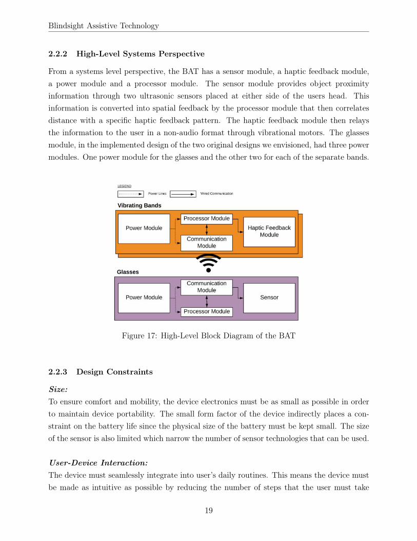
2.2.2 High-Level Systems Perspective
From a systems level perspective, the BAT has a sensor module, a haptic feedback module,a power module and a processor module. The sensor module provides object proximityinformation through two ultrasonic sensors placed at either side of the users head. Thisinformation is converted into spatial feedback by the processor module that then correlatesdistance with a specific haptic feedback pattern. The haptic feedback module then relaysthe information to the user in a non-audio format through vibrational motors. The glassesmodule, in the implemented design of the two original designs we envisioned, had three powermodules. One power module for the glasses and the other two for each of the separate bands.
Figure 17: High-Level Block Diagram of the BAT
2.2.3 Design Constraints
Size:To ensure comfort and mobility, the device electronics must be as small as possible in orderto maintain device portability. The small form factor of the device indirectly places a con-straint on the battery life since the physical size of the battery must be kept small. The sizeof the sensor is also limited which narrow the number of sensor technologies that can be used.
User-Device Interaction:The device must seamlessly integrate into user’s daily routines. This means the device mustbe made as intuitive as possible by reducing the number of steps that the user must take
19

Blindsight Assistive Technology
between purchasing the device and using it. In order to accomplish this goal, the device mustprovide clear feedback to the user in the form of simple and easily distinguishable vibrationpatterns for each scenario. Alerts regarding charging and battery status could also be addedthrough auditive or vibrating feedback depending on the user’s auditory level.
Studies have established a correlation between assistive device adaptability and device aban-donment. Rates of abandonment are typically greater for devices that are unable to matchthe changing needs of the user and when unfriendly design makes it difficult for the userto adapt the device to his needs [6]. Changing needs are common with progressive condi-tions such as muscular degeneration and muscular dystrophy. Given the target audience, itis expected that the device must be able to easily adapt to changes in pace, reaction timeand feedback intensity. Users may desire to receive warnings about obstacles at differentdistances over the time that they use the device and may require to adjust the intensityof the feedback for comfort. The user-friendly design of the device must take into accountthat the blind individual may encounter difficulties interacting with small, non differentiablebuttons as well as typical charging ports, especially non reversible or non magnetic ports.These requirements guide the desire to implement buttons with particular shapes, such as aplus symbol to increase vibration intensity, as well as wireless charging.
It is important to consider factors beyond the sensor characteristics during the value analy-sis. One such factor is the time course of the average action potential in a neuron as it is akey determinant in the maximum resolution of the device. With a time course of 1mS, themaximum resolution that the user could perceive is 17cm. The calculation of the resolutionfollows:
vsound × ActionPotential T imeCourse = Resolution (1)
344m/s× 1mS = 34.3cm (2)
34.4cm is the distance that the sound wave could travel in the time that it takes the signalto reach the brain. Given that object detection is a two way trip, the device could detect anobject that is 17cm away in that 1mS timeframe (Hoyle & Waters, 2010).
Environment-Device Interaction:It is important to consider the ruggedness of the device given that it will be used outdoors ina variety of conditions. The ideal device would include an Ingress Protection Rating (IPX)greater than or equal to IPX-55. This means that the device would be protected from water
20

Blindsight Assistive Technology
splashes in any direction. It is important that the device is capable of resisting shock as theuser may drop the device or bump it against an overhanging obstacle.
Society-Device Interaction:According to Hersh, “the symbolic identification of the cane with blindness means that thecane may be seen as only for totally blind people, leading to some partially sighted people,newly blind people, and people with progressive conditions finding it difficult to accept or de-laying cane use” (Pissaloux & Velázquez, 2017). Therefore, the device should be discrete, butit should (Alahakone & Senanayake, 2009) not follow the same approach as current medicaldevices that are meant to be hidden from view given their terrible aesthetic design (Pullin &Higginbotham, 2010). The device should ideally serve as a fashion item and the user shouldnot feel the need to hide it. It should complement the looks of the user. This will help theuser find the confidence to wear the device and beat the stigma. It is key that both the userand those around him find the device visually appealing. “Unsurprisingly blind people havebeen found to frequently share the general preference for small easily portable devices such asmobile and smartphones rather than larger more awkward and less easily portable devices"(Hersh, 2017).
Maintenance:The team desires to make the device highly modular and relatively low cost in order to keepany maintenance and repair costs as low as possible. The motivation behind this approachis to reduce the burden of owning the device may place on the owner. Following a visit tothe Abilities Conference in Boston, the team came to understand that there is little supportin terms of insurance coverage for assistive devices. This often means that the high costof assistive devices falls on the user. According to the National Census Bureau, visuallyimpaired individuals have a median income that is half the median income of the UnitedStates. Furthermore, the vast majority of visually impaired individuals are covered underMedicaid and Medicare, neither of which cover non medically prescribed assistive technolo-gies. This means that the users of the proposed device will most likely have to find alternatesources of funding to cover the device, and they are not guaranteed to find any. A short list,non comprehensive list of sources for assistive technology funding is available in the appendix.
The ultimate goal of the development of the device, regardless of its feasibility as a prod-uct around which a company may be built, is to provide a solution to improve the life ofvisually impaired individuals. Thus the development team wishes to open-source the designfiles for the device in hopes that the community of makers around assistive technologies will
21

Blindsight Assistive Technology
adopt the device and further its development well beyond what the current team is capableof achieving within the academic year timeframe.
2.2.4 Decision Matrix
Our general design approach was based on identifying specific categories that our customerswould find important based on our product specifications and trying to satisfy these categoriesin our final product. The list of selected categories is given below:
• Performance: Battery life
• Affordability: Price per unit
• Reliability: Accuracy, Response time
• Ease of Use: Intuitive to use, Comfort
• Design: Durability, Acceptable aesthetic design, Modularity
Each component was given a specific sub-categories that was used to determine the overallmain category ratings. In order to quantify the importance of the above qualities in eachproduct, we developed a decision matrix. In this ranking technique, each cell’s row categorywas compared to it’s column category. The sum of each row was then scaled based onthe importance of each factor. The total score of each component helped us prioritize theimportance of different device characteristics in our final product.
Table 2: Decision Matrix for Rank Ordering of Design Goals
22

Blindsight Assistive Technology
2.2.5 Weight Assesment
The decision matrix above helped us prioritize our design considerations. A numerical valueof “1” was given if the row category was deemed more important than the column category.Similarly, a numerical value of “0” was given if the opposite was considered true. A “0.5”was given for two design categories that were of equal importance and priority. Based on theresults above, a weight from 1 to 5, 1 being of the least priority and 5 being of the highestpriority, was given to each design condition. These assignments and their justification aregiven below.
1. Reliability: Device must accurately detect objects within its sensor’s range with nofalse positives or false negatives.
• Weight:100
• The reliability of our BAT is a critical customer requirement due to the catego-rization of our device as a medical assistive technology. Even though the devicewill not be FDA approved and therefore will not have to adhere by official medicaldevice stipulations, the potential liability associated with a poor accuracy sensingis very high. Furthermore, a main selling point for BAT is its low cost without acompromise in quality of detection. For these reasons, this design condition wasgiven the highest weight factor.
2. Design: Device must be physically appealing, pass Ingress Protection Marking-55 (IP-55) durability testing, and have a modular design.
• Weight: 65
• A common theme witnessed with assistive technologies is their lack of penetra-tion and use in the the target market. Reasons for this have been pinpointed tosocial stigmas against devices as well as the inconvenience of using a device incertain situations. For this reason, making our device look physically appealing isconsidered of utmost importance in ensuring the use of our device by blind indi-viduals. Durability and modularity are also important customer requirements tomake BAT more convenient to use. For these reasons, this design condition wasgiven the second highest weight factor.
3. Ease of Use: Device must be intuitive to operate and comfortable to wear.
• Weight: 50
23

Blindsight Assistive Technology
• The target market for BAT is all blind individuals which includes a broad rangeof technological literacy. For this reason, our device must be developed such thatits operation is as intuitive as possible. This can be achieved by mimicking thefront-end design of common devices such as home appliances. Since the device isintended for prolonged use, comfort is also prioritized as an important customerrequirement. For these reasons, this design condition was given the middle weightfactor.
4. Performance: Device must be able to operate on only the battery for a minimum of 10hours, 2 hours continuously with intermittent use for the other 8 hours.
• Weight: 40
• Regardless of the fulfillment of the other customer requirements and any addedbenefit the device gives to the user, if the BAT cannot last for the expected oper-ation period than the device becomes ineffective. Therefore, to ensure that blindindividuals are able to rely on the device to enhance their quality of life the assis-tive technology must be backed up with a powerful battery. The implementationof this design condition is fairly simple, therefore this consideration was given thesecond lowest weight factor.
5. Affordability: Device cost per unit must be less than $75.
• Weight: 25
• A low cost for our device would allows the BAT to target a larger market space.However, if the cost exceeds the stated threshold this would simply narrow ourmarket. For this reason, seeing as this customer requirement is not of criticalimportance it was given the lowest weight factor.
2.3 Specific Module Design Options
In the previous section, the general design categories were identified and ranked. This pri-oritization was useful in the overall product development process. However, when choosingspecific components used in our device the categories were made more specific. When choos-ing the components, multiple models and brands were compared based on technical specifi-cations. The final decision was made keeping the broad customer requirement themes in mind.
During the value analysis, each component was given different subcategories that helped
24

Blindsight Assistive Technology
determine the overall top category. The overall top category was assigned as the rating aver-age of all subcategories. This approach gave us a better understanding of the specific featuresthat each component was capable of delivering, and how it was valued for our application.
2.3.1 Sensor
Table 3: Value Analysis for Sensor
• Ultrasonic Two-Can HC-SR04
– Reliability: The range and field of view (FOV) is at an average level. The samplingfrequency and resolution are also at a mid-level compared to the other sensors.
– Design: This sensor scores very poorly in the design category due to its largesize. The two-can design is bulky and if used would probably not be physicallyappealing.
– Performance: The active and quiescent current consumption is very high whichwill reduce battery life significantly.
– Affordability: The cost per unit is the lowest of the three sensors and decreasesas more units are purchased.
25

Blindsight Assistive Technology
• Ultrasonic One-Can MB1040
– Reliability: The range and field of view (FOV) for this sensor is very good. Incontrast, the sampling frequency and resolution are at a mid-level compared tothe other sensors.
– Design: This sensor scores better than the previous sensor because only one-canis used to both transmit and receive which makes the design less bulky.
– Performance: The active and quiescent current consumption is very low whichgreatly improves battery life.
– Affordability: The cost per unit is very high but goes down as more units arepurchased.
• Time of Flight VL53L0X
– Reliability: The range and field of view (FOV) for this sensor is at an averagelevel. The sampling frequency is very high which implies that the sensor has avery high resolution.
– Design: The sensor is made using a very small Single Photon Avalanche Diodeswhich gives it a desirable compact form factor.
– Performance: The active current is very high for this sensor but is compensatedby the very low quiescent current consumption.
– Affordability: The cost per unit at a mid-range level but goes down as more unitsare purchased.
26

Blindsight Assistive Technology
2.3.2 Haptic Feedback Actuator
Table 4: Value Analysis for Haptic Feedback Actuator
• Precision Vibration Motor 310-101
– Reliability: The vibration amplitude is at an acceptable level such that the usercan recognize any received feedback. The maximum frequency of vibrations isfairly low which may increase the response time afforded to the whole device.
– Design: The small diameter and low weight of the motor makes it ideal for theBAT application where concealment of the sensor and comfort are critical customerrequirements.
– Performance: The high current consumption is highly undesirable due to thebattery-powered nature of the device.
– Affordability: The sensor is relatively inexpensive and the price goes down as moreunits are purchased.
• Seeed Tech Vibration Motor 31604004
– Reliability: The vibration amplitude is at an acceptable level such that the usercan recognize any received feedback. The maximum frequency of vibrations iseven lower than the previous motor which only increases device response time.
27

Blindsight Assistive Technology
– Design: The small diameter and low weight of the motor makes it ideal for theBAT application. The weight is lower than the previous sensor which makes thedevice more comfortable to wear.
– Performance: The high current consumption is again highly undesirable due tothe battery-powered nature of the device.
– Affordability: The sensor is inexpensive and the price goes down as more unitsare purchased.
• Micro Servo SG90C
– Reliability: The vibration amplitude is at an acceptable level such that the user canrecognize any received feedback. The maximum frequency is at a high enough levelthat it response is faster than the fastest reaction time the device will encounterwhile attempting to avoid objects.
– Design: Compared to the vibrating motors, the device is more bulky and harderto conceal. However, it is still small enough that a haptic feedback design canlook discrete.
– Performance: The current consumption is not given, however based on the natureof motors it is likely that a significant current draw will be seen (> 100mA).
– Affordability: The sensor is relatively expensive but the price goes down as moreunits are purchased.
28

Blindsight Assistive Technology
2.4 Microcontroller
Table 5: Value Analysis for Microcontroller
• Arduino Pro Mini
– Reliability: The score for this design category is estimated based on the expectedfailure that might occur in different circuits due to manufacturing discrepanciesbetween different units. To quantify this, the number of false positives that mightarise due to the speed of information processing is considered.
– Performance: The active and quiescent current consumption is very low which ishighly desirable to prolong battery life.
– Affordability: The sensor is relatively inexpensive and the price goes down as moreunits are purchased.
• NodeMCU
– Reliability: Again, the score for this design category is estimated based on thenumber of false positives expected. The NodeMCU is manufactured by a lessestablished company compared to the other two microcontrollers, therefore thequality of manufacturing was predicted to be lower explaining the lowered score.
– Performance: The active and quiescent current consumption is very high whichwould significantly reduce battery life.
29

Blindsight Assistive Technology
– Affordability: The sensor is relatively inexpensive and the price goes down as moreunits are purchased. However, the reduced price does not compensate adequatelyfor the inferior characteristics that the MCU has in comparison to its competitors.
• MSP430 Ultra Low-Power
– Reliability: The MSP430 is a very reliable chip that has been tried and testedfor many years in numerous applications. Furthermore, Texas Instruments is anestablished company therefore number of false positives expected is very low.
– Performance: The active and quiescent current consumption is very low which isgreat for the device battery life.
– Affordability: The sensor is slightly more expensive than its competitors but theprice is justified by the low power consumption and reliability of the device.
30

Blindsight Assistive Technology
2.5 Battery
Table 6: Value Analysis for Battery
• NiMh HHR-70AAAE4
– Reliability: For batteries, the reliability is directly linked to the performance be-cause the battery life decides how much the developed can depend on the deviceto last. In terms of manufacturing discrepancies, all three batteries are assumedto have an equal quality of manufacturing therefore the reliability is not affectedby individual battery characteristics.
– Design: This battery comes in a cylindrical double AA form factor is thereforefairly bulky and difficult to conceal.
– Performance: The average discharge capacity is very high, however, the nominalvoltage is low relative to the average microcontroller operating voltage. Thismeans that for this battery multiple units would have to be put in series.
– Affordability: The low cost of the battery and its prevalence in most departmentstores are both very attractive product features.
• LiPo 301120
– Reliability: Look at previous battery description.
31

Blindsight Assistive Technology
– Design: This battery comes in a flat disc form factor which is easy to conceal andallows greater variability in overall device form.
– Performance: The average discharge capacity is at the mid-range level high, how-ever, the nominal voltage exceeds the average microcontroller operating voltage.
– Affordability: The low cost of the battery and ubiquitousness of the battery areboth desirable features.
• Supercapacitor BZ055B203ZSB
– Reliability: Look at previous battery description.
– Design: This battery comes in a bulky package that is hard to conceal.
– Performance: The nominal voltage exceeds the average microcontroller operatingvoltage.
– Affordability: The high cost of the component and the lack of prevalence in ordi-nary consumer stores makes this option very unattractive.
32

Blindsight Assistive Technology
2.6 Power Management Integrated Circuit
Table 7: Value Analysis for Power Management IC
• LTC3106
– Reliability: This component is produced by Linear Technologies, an establishedcompany with a very good reputation in industry, therefore the number of defectbetween individual products due to manufacturing discrepancies is expected to below.
– Design: Support for a Lithium Polymer battery is critical when choosing this ICbecause that is the battery that is likely to be used based on the previous valueanalysis.
– Performance: The quiescent current consumption is low which is a desirable fea-ture for this component.
– Affordability: This component is relatively expensive, but the price goes down asmore units are purchased.
• STC3117
– Reliability: This component is produced by ST Microelectronics therefore thereliability of the device is very high since manufacturing discrepancies betweenindividual units can be expected to be low.
– Design: This device supports both Li-Ion and Li-Po battery charging.
33

Blindsight Assistive Technology
– Performance: The quiescent current consumption is fairly low. The active currentconsumption is really good in comparison to the competing products.
– Affordability: This component is very inexpensive compared to other productsand the cost only goes down as more units are purchased.
• BQ24079
– Reliability: This component is produced by MicroChip therefore the manufactur-ing tolerances are very high and adherence to the standard is expected to be verygood.
– Design: This device supports both Li-Ion and Li-Po battery charging.
– Performance: The quiescent current consumption is very low which is attractivefor wearable devices because of the boost it will provided in terms of battery life.
– Affordability: This component is comparatively very cheap and the price goesdown as more units are purchased.
2.7 Gantt Chart
Following the iterative design methodology, the timeline that was adopted followed a cyclicprototyping approach. First, the sensors were tested in an initial rough prototype. Followingthis, each module was tested separately with standalone circuitry. Inputs from other modulesnecessary for the testing of the module in question were simulated using software. Afterverifying the functionality of all the modules on their own, each of the standalone circuitswere individually integrated into a larger board. This system integration phase generatedmultiple prototypes as the circuit was tested after the addition of each significant module.
Figure 18: Visual demonstrating the specific approach followed in the design of the BAT inchronological order
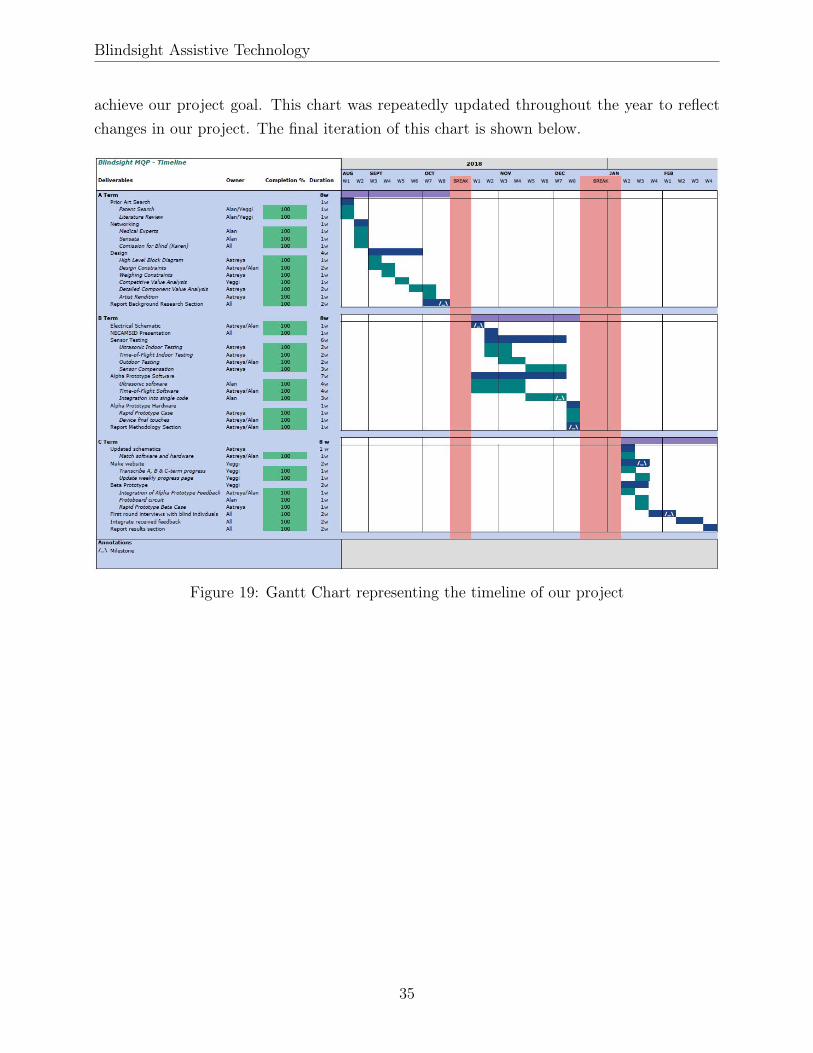
A gantt chart was made at the very beginning of the project to outline a structured plan to
34
Blindsight Assistive Technology
achieve our project goal. This chart was repeatedly updated throughout the year to reflectchanges in our project. The final iteration of this chart is shown below.
Figure 19: Gantt Chart representing the timeline of our project
35

Blindsight Assistive Technology
3 Product Development
In this section, the application of the iterative design methodology in our project is exploredin detail. The testing and integration of each module and feature is discussed in chronologicalorder.
3.1 Sensor Module Integration
3.1.1 Sensor Testing
Initially, two sensors were considered for our device: the VL53L0X Infrared Ranging Sensorand the MB1020 Ultrasonic Sensor. To determine which component would be best for ourapplication, the sensors were tested in different environments. The same test was carried outfor both components. The sensor circuit was mounted to a movable cart and a cardboardsheet was placed in front of it. The distance from the sheet to the sensor was increased inconsistent increments until the distance readings were maxed out. This test was carried outin an indoor and outdoor setting. The indoor setting was a tight corridor and the outdoorsetting was a open driveway. These settings best simulate the environments that our devicewould encounter.
Figure 20: Testing MB1020 Ultrasonic sensors outdoors in an open driveway
A secondary objective of sensor testing was to verify if the sensor data given in each compo-nent’s datasheet was accurate. Therefore, the results for each sensor were compared to the
36

Blindsight Assistive Technology
typical performance specifications found in their respective datasheets.
VL53L0X Testing:
Figure 21: Standalone circuit used to test the VL53L0X Infrared Sensor
The circuit shown in figure 21 was used to test the functionality of the VL53L0X Infraredsensor. In the circuit, there are four common lines coming from the microcontroller: power,ground, shared clock line (SCL) and shared data line (SDA). The SDA and SCL lines belongto the I2C bus that is used to collect the proximity data generated by each sensor. Eachsensor has a unique XSHUT line connected to individual digital pins on the microcontroller.Since the data lines are shared among sensors, the XSHUT pin is used to ensure that no twosensors are sending data at the same time.
According to the sensor datasheet, when the sensor is in default mode the proximity datashould follow a fairly linear calibration graph very close to the line of identity (ST Micro-electronics, 2018).
Figure 22: Expected calibration graph given in the VL53L0X datasheet
37

Blindsight Assistive Technology
After performing our own testing (for which the raw data can be found in Appendix A), asimilar linear trend was observed with an average sensitivity of 1.0007 mm/mm. This is veryclose to the ideal sensitivity of 1 mm/mm described in the sensor datasheet. An averageDC offset of -36.1 mm was also recorded. Due to the low resolution that is needed for ourapplication, this offset was not considered significant. The maximum distance the VL53L0Xsensors were able to detect was around 1.75 m.
MB1020 Testing:
Figure 23: Standalone circuit used to test the MB1020 Ultrasonic Sensor
The circuit shown in figure 23 was used to test the functionality of the MB1020 Ultrasonicsensor. The two common lines in this circuit are the power and the ground. Each com-ponent’s receiver (RX) pin is connected to the previous component’s transmitter (TX) pin.The reason for this setup is due to the way the sensors are configured. According to thedatasheet, in order to avoid multiple sensors pinging at the same time the first sensor pro-duces a signal that triggers the next sensor on the chain. This signal is generated once thesensor has finished collecting data or after 50ms have elapsed. This process then continuesuntil the last sensor is reached. The unique connection on each component, the pulse width(PW) pin, communicates the proximity information to a digital pin. The length of the pulsewidth directly correlates with the proximity value that is being reported.
There are two other recommended configurations in the manufacturer-provided datasheetthat could have been used. The first one, a "PW Output Constantly Looping" configura-tion, is a slight modification on the "PW Output Commanded Loop" configuration that wasused in our final circuit. The modification is the feeding back of the TX pin to the RX pinof the first sensor resulting in a circuit that requires only a single trigger to start a cyclicsensor collecting cycle. The other alternative configuration is the "PW Output Simultaneous
38
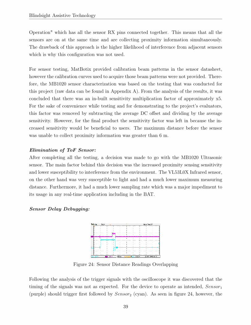
Blindsight Assistive Technology
Operation" which has all the sensor RX pins connected together. This means that all thesensors are on at the same time and are collecting proximity information simultaneously.The drawback of this approach is the higher likelihood of interference from adjacent sensorswhich is why this configuration was not used.
For sensor testing, MatBotix provided calibration beam patterns in the sensor datasheet,however the calibration curves used to acquire those beam patterns were not provided. There-fore, the MB1020 sensor characterization was based on the testing that was conducted forthis project (raw data can be found in Appendix A). From the analysis of the results, it wasconcluded that there was an in-built sensitivity multiplication factor of approximately x5.For the sake of convenience while testing and for demonstrating to the project’s evaluators,this factor was removed by subtracting the average DC offset and dividing by the averagesensitivity. However, for the final product the sensitivity factor was left in because the in-creased sensitivity would be beneficial to users. The maximum distance before the sensorwas unable to collect proximity information was greater than 6 m.
Elimination of ToF Sensor:After completing all the testing, a decision was made to go with the MB1020 Ultrasonicsensor. The main factor behind this decision was the increased proximity sensing sensitivityand lower susceptibility to interference from the environment. The VL53L0X Infrared sensor,on the other hand was very susceptible to light and had a much lower maximum measuringdistance. Furthermore, it had a much lower sampling rate which was a major impediment toits usage in any real-time application including in the BAT.
Sensor Delay Debugging:
Figure 24: Sensor Distance Readings Overlapping
Following the analysis of the trigger signals with the oscilloscope it was discovered that thetiming of the signals was not as expected. For the device to operate as intended, Sensor1(purple) should trigger first followed by Sensor2 (cyan). As seen in figure 24, however, the
39

Blindsight Assistive Technology
trigger signal for Sensor2 was taking place before that of Sensor1. This was indicative of amajor issue with either the software or the hardware as Sensor1 produces the trigger signalthat activates Sensor2. The waveform suggested that Sensor2 was ranging regardless of thetrigger signal produced by Sensor1. As a result of this unexpected behavior, Sensor1 wasproducing smaller measurements than expected even though both sensors were placed at thesame distance from the the same obstacle. When Sensor2 was obstructed, the resulting pulsedecreased, as expected, and Sensor1 reported the expected distance to the obstacle. Sinceno inconsistencies were found between the suggested wiring of the sensors in the datasheetand the prototype, it was concluded that there must have been a problem with the hardwareitself. More specifically, that the circuitry to produce the TX signal at Sensor1 was notworking properly. The sensors were then connected directly to the MCU to be triggeredindividually. The new configuration resulted in the correct, expected waveform from bothsensors. This configuration introduces a small, negligible delay since the MCU triggers thenext sensor when it recognizes the end of the distance measurement instead of the arrival ofthe ultrasonic pulse to the sensor. The alternative configuration, where one sensor triggersthe next, does not suffer from this delay because the next sensor is triggered immediatelyupon the arrival of the ultrasonic pulse.
3.2 Motor Module Integration
Figure 25: Standalone circuit used to test the ST Vibrating motor
The circuit shown in figure 25 was used to test the operation of the ST Vibrating motor. Inthe circuit, a BJT with an emitter and a base resistor is used. The base resistance reducescurrent sourcing from the base and the emitter resistor is used to limit current flow throughthe motor.
Initially when testing the motor, the current characteristics that were observed were ab-
40

Blindsight Assistive Technology
normal. Rather than seeing a clean square wave as expected, some major transient effectswere present.
Figure 26: Motor current characteristics acquired by measuring the potential across the1ohm base resistor
In the blown-up view in Figure 26, two consecutive signal periods are shown. In the sec-ond waveform period, a relatively clean square wave is visible. In contrast, the first periodexhibits a large transient in the high band. After some testing, we determined that thereason for this was the frequency of pulse-width modulated (PWM) signal generated by theArduino was matching the frequency of the mechanical movement of the vibrating motor.The conclusion that was reached was that the off centering of the internal weight in the shaftof the motor was occurring at the same time as the transition of the PWM signal from highto low resulting in second-order transients in the early part of the high band. By simplychanging the Arduino PWM signal property from "default PWM" (977Hz) to "Fast PWMmode" (16MHz), the motor current waveform became significantly cleaner.
41
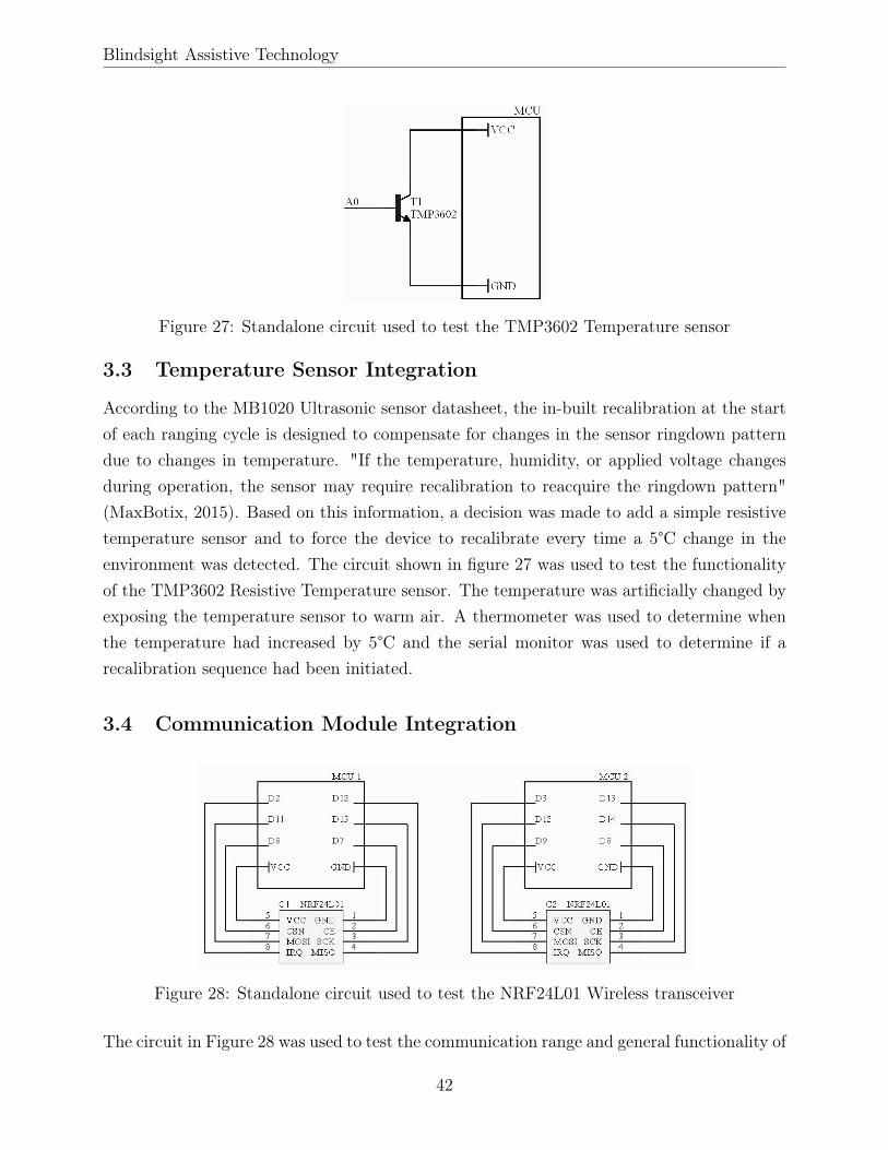
Blindsight Assistive Technology
Figure 27: Standalone circuit used to test the TMP3602 Temperature sensor
3.3 Temperature Sensor Integration
According to the MB1020 Ultrasonic sensor datasheet, the in-built recalibration at the startof each ranging cycle is designed to compensate for changes in the sensor ringdown patterndue to changes in temperature. "If the temperature, humidity, or applied voltage changesduring operation, the sensor may require recalibration to reacquire the ringdown pattern"(MaxBotix, 2015). Based on this information, a decision was made to add a simple resistivetemperature sensor and to force the device to recalibrate every time a 5°C change in theenvironment was detected. The circuit shown in figure 27 was used to test the functionalityof the TMP3602 Resistive Temperature sensor. The temperature was artificially changed byexposing the temperature sensor to warm air. A thermometer was used to determine whenthe temperature had increased by 5°C and the serial monitor was used to determine if arecalibration sequence had been initiated.
3.4 Communication Module Integration
Figure 28: Standalone circuit used to test the NRF24L01 Wireless transceiver
The circuit in Figure 28 was used to test the communication range and general functionality of
42

Blindsight Assistive Technology
the NRF24L01 Wireless transceiver. In the circuit, there are two transceivers, each connectedto a different microcontroller. The NRF chip is controlled through the SPI ports Master-In-Slave-Out (MISO) and Master-Out-Slave-In (MOSI). Subsequently, a Shared Clock (SCK)pin is necessary between the Master and Slave to synchronize communication and a SPIEnable (CSN) pin is necessary to turn serial communication on and off. Finally, the ChipEnable (CE) pin is used to turn on and off communication between chips and the InterruptRoutine (IRQ) pin is used to trigger a hardware interrupt.
Figure 29: Standalone circuit used to test the NRF24L01 Wireless transceiver along with asingle sensor
The circuit in Figure 29 was used to measure the delay of the combined communication andsensor modules to isolate the components contributing to a high overall system delay. In thiscircuit, there are two transceivers. One transceiver is connected to a single ultrasonic sensor.The data that is received from the sensor is sent to the next transmitter. This process iscarried out repeatedly. The main purpose of this circuit was to identify delays in our system.However, during this process a more significant problem was uncovered. When hooking upthe trigger pin, the pin used to initiate ranging in the sensor, to an oscilloscope along withsensor pulse width pin, the output trigger pin output was expected to be a 20µS square pulse.However, what was observed was a sharp transition followed by an extended decaying periodas shown in Figure 30. Connecting a 1kΩ resistor from the trigger pin to ground resultedin a 60Hz power line noise wave to be displaying on the oscilloscope. This suggested thatthe PWM output node from the Arduino had a very high impedance. Subsequently, placinga small resistance in parallel with a high resistance resulted in the lower resistance voltageappearing "stronger" than the actual PWM signal.
43
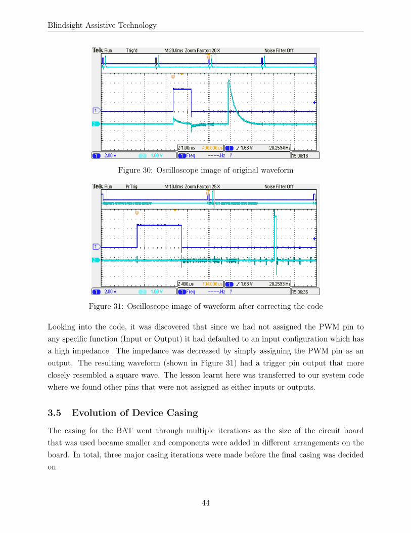
Blindsight Assistive Technology
Figure 30: Oscilloscope image of original waveform
Figure 31: Oscilloscope image of waveform after correcting the code
Looking into the code, it was discovered that since we had not assigned the PWM pin toany specific function (Input or Output) it had defaulted to an input configuration which hasa high impedance. The impedance was decreased by simply assigning the PWM pin as anoutput. The resulting waveform (shown in Figure 31) had a trigger pin output that moreclosely resembled a square wave. The lesson learnt here was transferred to our system codewhere we found other pins that were not assigned as either inputs or outputs.
3.5 Evolution of Device Casing
The casing for the BAT went through multiple iterations as the size of the circuit boardthat was used became smaller and components were added in different arrangements on theboard. In total, three major casing iterations were made before the final casing was decidedon.
44

Blindsight Assistive Technology
First Iteration Casing:
Figure 32: Top view of first iteration of casing
The first iteration, shown in Figure 32, three sensors were placed at the right, left and centerof the frame (circled in red). When this casing was made, the communication module hadnot been integrated into our system and the majority of the circuitry excluding the sensorswere still on a breadboard. Therefore, the casing was made with hollow frames to allow wiresto run from the breadboard to the sensors (wire entry points circled in green).
Figure 33: Front view of first iteration of casing
Some important lessons were learnt from this casing iteration. Firstly, it was clearly visiblethat a third sensor was not a viable options due to the base of the sensor PCB hitting thebridge of the user’s nose. Another mistake that we were able to identify in our design was theuse of hollow tubes that increased the thickness of the frames significantly. This made theglasses heavy and uncomfortable to wear as they did not sit well on the ridge of the user’s ear.
45
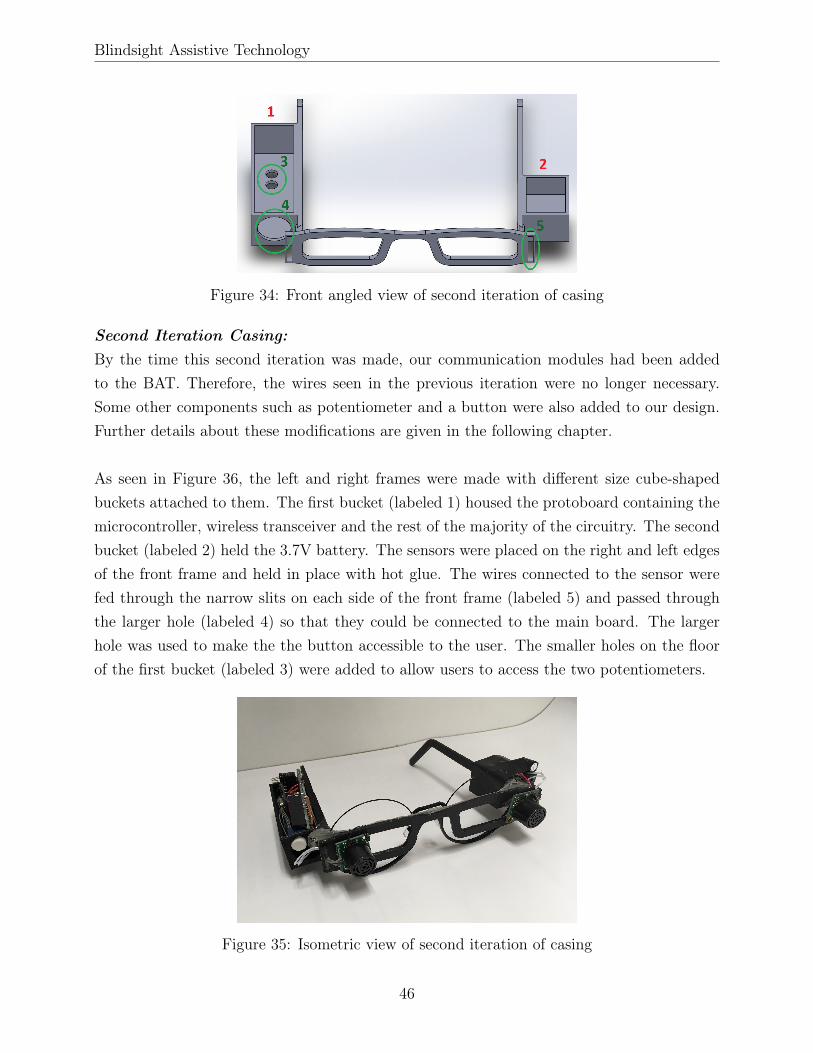
Blindsight Assistive Technology
Figure 34: Front angled view of second iteration of casing
Second Iteration Casing:By the time this second iteration was made, our communication modules had been addedto the BAT. Therefore, the wires seen in the previous iteration were no longer necessary.Some other components such as potentiometer and a button were also added to our design.Further details about these modifications are given in the following chapter.
As seen in Figure 36, the left and right frames were made with different size cube-shapedbuckets attached to them. The first bucket (labeled 1) housed the protoboard containing themicrocontroller, wireless transceiver and the rest of the majority of the circuitry. The secondbucket (labeled 2) held the 3.7V battery. The sensors were placed on the right and left edgesof the front frame and held in place with hot glue. The wires connected to the sensor werefed through the narrow slits on each side of the front frame (labeled 5) and passed throughthe larger hole (labeled 4) so that they could be connected to the main board. The largerhole was used to make the the button accessible to the user. The smaller holes on the floorof the first bucket (labeled 3) were added to allow users to access the two potentiometers.
Figure 35: Isometric view of second iteration of casing
46

Blindsight Assistive Technology
From this design, we were able to identify some major areas for improvement. For one, theangle of the nose bridge was too wide which resulted in the glasses slowly sliding down theuser’s nose. It was decided that in future designs the nose angle would be modeled of labsafety glasses which have a bridge width of around 18 in (Grainger, 2015). It was also notedthat from an aesthetic standpoint the first bucket was too large, therefore future iterationswould need a smaller PCB so that the bucket could be reduced.
Third Iteration Casing:
Figure 36: Isometric view of third iteration of casing
In the third iteration, the weaknesses in the previous iteration design were addressed. Thelarge buckets on either side of the glasses were reduced significantly (labeled 1 and 2 in Figure36). The potentiometers and button were removed from inside the bucket and moved to theright frame (circled in green) to make them more accessible. The narrow slits on either sideof the glasses were replaced with holes. Finally, the bridge width was reduced to ensure thatthe glasses didn’t slide down.
In this iteration, we found that the bridge needs to be reduced even more than it alreadyhad been. To accommodate the potentionmeters and button, the first bucket was movedfurther back towards the user’s ear which made the design less comfortable. These issueswere fixed in the final iteration which served as the casing for our final product. That casingis explained in the following chapter.
47

Blindsight Assistive Technology
4 Systems Level Device Description
4.1 Hardware Architecture
The two main circuits comprising the hardware for the BAT device are the glasses andband circuits. Referring to Figure 17, the glasses circuit is the implementation of the purple"Glasses" block. The main functionality of this circuit is to record sensor information, con-vert it to appropriate vibrating patterns, and send this information to the vibrating bands.The band circuit is the implementation of the orange "Vibrating Bands" blocks which re-ceives the vibrating pattern data from the glasses. These pattern values are then used tovibrate a motor. In this way, proximity information received at the glasses is correlated tovibrations at the bands. A deeper look at each circuit is given below.
Figure 37: Final glasses system circuit
Starting off with the glasses circuit, the modules that were mentioned in the "Product De-velopment" section including the ultrasonic sensors, temperature sensor, and the 2.4GHztransceiver were integrated into a single circuit with relative ease. Some additional compo-nents were added including two potentionmeters, a button, and an NPN transistor. Thepotentiometers were added to control the sensitivity and maximum vibration intensity of thebands. The button and transistor were used to pause the vibrations and put the whole systeminto low power mode. Once the button is pressed, the transistor switch cuts the power to thewhole system. This feature was added to allow the user to turn off the device when enteringan environment that they are familiar with. The reasoning behind this decision was that insuch environments the vibrations might be unnecessary or even distracting. An additionalbenefit of this is the reduced power consumption while the device is in low power mode.
48
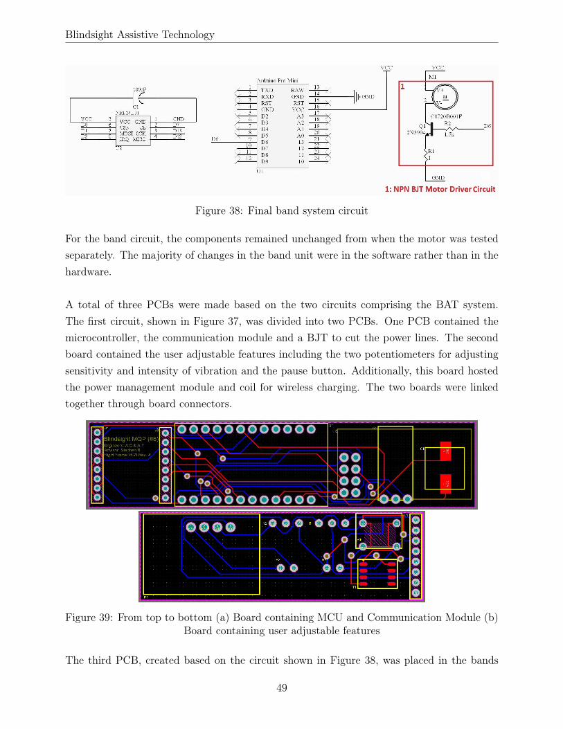
Blindsight Assistive Technology
Figure 38: Final band system circuit
For the band circuit, the components remained unchanged from when the motor was testedseparately. The majority of changes in the band unit were in the software rather than in thehardware.
A total of three PCBs were made based on the two circuits comprising the BAT system.The first circuit, shown in Figure 37, was divided into two PCBs. One PCB contained themicrocontroller, the communication module and a BJT to cut the power lines. The secondboard contained the user adjustable features including the two potentiometers for adjustingsensitivity and intensity of vibration and the pause button. Additionally, this board hostedthe power management module and coil for wireless charging. The two boards were linkedtogether through board connectors.
Figure 39: From top to bottom (a) Board containing MCU and Communication Module (b)Board containing user adjustable features
The third PCB, created based on the circuit shown in Figure 38, was placed in the bands
49
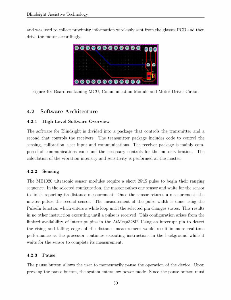
Blindsight Assistive Technology
and was used to collect proximity information wirelessly sent from the glasses PCB and thendrive the motor accordingly.
Figure 40: Board containing MCU, Communication Module and Motor Driver Circuit
4.2 Software Architecture
4.2.1 High Level Software Overview
The software for Blindsight is divided into a package that controls the transmitter and asecond that controls the receivers. The transmitter package includes code to control thesensing, calibration, user input and communications. The receiver package is mainly com-posed of communications code and the necessary controls for the motor vibration. Thecalculation of the vibration intensity and sensitivity is performed at the master.
4.2.2 Sensing
The MB1020 ultrasonic sensor modules require a short 25uS pulse to begin their rangingsequence. In the selected configuration, the master pulses one sensor and waits for the sensorto finish reporting its distance measurement. Once the sensor returns a measurement, themaster pulses the second sensor. The measurement of the pulse width is done using thePulseIn function which enters a while loop until the selected pin changes states. This resultsin no other instruction executing until a pulse is received. This configuration arises from thelimited availability of interrupt pins in the AtMega328P. Using an interrupt pin to detectthe rising and falling edges of the distance measurement would result in more real-timeperformance as the processor continues executing instructions in the background while itwaits for the sensor to complete its measurement.
4.2.3 Pause
The pause button allows the user to momentarily pause the operation of the device. Uponpressing the pause button, the system enters low power mode. Since the pause button must
50

Blindsight Assistive Technology
Figure 41: Visual representation of how our code flows through different functions andstates
be able to interrupt the operation of the device at any time, it is handled using an externalinterrupt. According to the documentation for the ATmega328P, there are two pins that areenabled for external interrupts: D2, D3. Since pin 2 is used by the NRF24, the momentarypush-button is connected to pin 3. The pin is externally pulled-up with a resistor such thatpressing the button brings the potential at the pin to ground.
When the button is pressed, the processor immediately jumps to the assigned handler func-tion for the interrupt. The ISR simply inverts the current state of the device, which is storedin a global boolean. The button is debounced using a simple delay which checks that thelogic level at the pin is the same after a number of milliseconds.
void PAUSE_ISR()
lastDebounce = micros();
while(micros() - lastDebounce < 5000)
lastDebounce = micros();
51

Blindsight Assistive Technology
if(PAUSE_PIN)
blindsight_running = !blindsight_running;
Upon exiting the ISR, the code executes the necessary commands to place the processor inlow power mode.
void low_power_mode()
for (byte node = 0; node < NUMBER_OF_SENSORS; node++)
radio.openWritingPipe(nodeAddresses[node]);
bool tx_sent;
int LPM = 999;
tx_sent = radio.write(&LPM, sizeof(LPM));
if (tx_sent)
if (radio.isAckPayloadAvailable())
radio.read(&remoteNodeData[node], sizeof(remoteNodeData[node]));
else
;;
else
;;
// Wait until PAUSE button is released before entering LPM
while(digitalRead(PAUSE_PIN) == LOW)
;;
radio.powerDown();
attachInterrupt(1, PAUSE_ISR, LOW);
LowPower.powerDown(SLEEP_FOREVER, ADC_OFF, BOD_OFF);
detachInterrupt(1);
radio.powerUp();
52

Blindsight Assistive Technology
The low power mode sequence first commands both slave nodes to sleep. Once the nodesacknowledge the receipt of their commands, the interrupt is attached to the Pause pin againand the device enters ultra low power mode. In this mode all oscillators are off and the onlyway to wake the device is through the external trigger generated by the Pause pin.
When the user presses the pause button, the device immediately continues the executionof the function, detaches the interrupt, and begins ranging again. The interrupt is not re-attached until a few seconds have elapsed and the button is no longer pressed. These twoconditions are included to stop erratic behavior if the user were to hold down the button toturn the device on or if he were to press the button multiple times in a row.
if(millis() - last_pause > 5000 &&
!pause_interrupt_set &&
digitalRead(PAUSE_PIN) == HIGH)
attachInterrupt(1, PAUSE_ISR, LOW);
pause_interrupt_set = true;
4.2.4 Sensitivity Adjustment
The device is intended to accommodate to the widest possible range of users. This require-ment means that the device must accommodate the gait of people of different heights. Sincea taller person will reach an object in less steps than a shorter person, it is expected that thetaller individual may want the device to start detecting obstacles that are slightly furtheraway than the shorter individual might find necessary. This change in sensitivity is achievedby selecting the detection distance using a potentiometer. Although the detection distanceof the utrasonic sensors is 6 meters, a hard limit is placed at 2 meters. The user may adjustthe detection distance within the 2 meter limit. For comparison, the range of detection ofthe long cane is approximately 1.2 meters.(Pyun, Kim, Wespe, Gassert, & Schneller, 2013).
4.2.5 Intensity Adjustment
Intensity = 255− (ADCV alue−MinADCV alue)
(MaxADCV alue−MinADCV alue)∗ 255, (3)
In order to accommodate for comfort, the user is given the option to adjust the intensityof the vibrations. The vibration intensity may be adjusted using a potentiometer. Thisadjustment will change the intensity for all three buckets at the same time. The code below
53
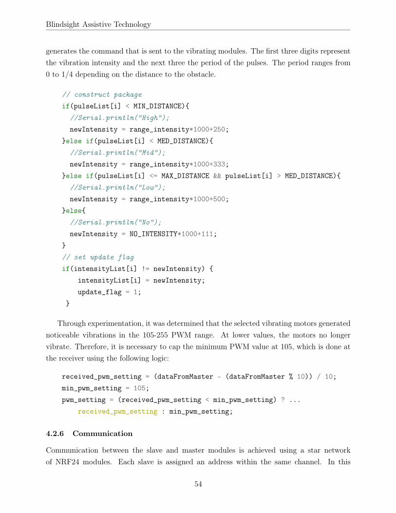
Blindsight Assistive Technology
generates the command that is sent to the vibrating modules. The first three digits representthe vibration intensity and the next three the period of the pulses. The period ranges from0 to 1/4 depending on the distance to the obstacle.
// construct package
if(pulseList[i] < MIN_DISTANCE)
//Serial.println("High");
newIntensity = range_intensity*1000+250;
else if(pulseList[i] < MED_DISTANCE)
//Serial.println("Mid");
newIntensity = range_intensity*1000+333;
else if(pulseList[i] <= MAX_DISTANCE && pulseList[i] > MED_DISTANCE)
//Serial.println("Low");
newIntensity = range_intensity*1000+500;
else
//Serial.println("No");
newIntensity = NO_INTENSITY*1000+111;
// set update flag
if(intensityList[i] != newIntensity)
intensityList[i] = newIntensity;
update_flag = 1;
Through experimentation, it was determined that the selected vibrating motors generatednoticeable vibrations in the 105-255 PWM range. At lower values, the motors no longervibrate. Therefore, it is necessary to cap the minimum PWM value at 105, which is done atthe receiver using the following logic:
received_pwm_setting = (dataFromMaster - (dataFromMaster % 10)) / 10;
min_pwm_setting = 105;
pwm_setting = (received_pwm_setting < min_pwm_setting) ? ...
received_pwm_setting : min_pwm_setting;
4.2.6 Communication
Communication between the slave and master modules is achieved using a star networkof NRF24 modules. Each slave is assigned an address within the same channel. In this
54

Blindsight Assistive Technology
configuration, all the slaves receive the same data packets, but disregard any packet that isnot addressed to them.
In order to communicate with the receivers, the master establishes a channel to which itwill write and the receivers will listen to. Within the channel, the master opens a writingpipe for each receiver. A single pipe is open at any one time and it basically representsa specific receiver address. Each receiver listens to its own pipe. This means that all thereceivers will receive the same packages, but they will only pay attention to those packagesthat are addressed to them. In other words, they will only listen to the package that is intheir own pipe. The master sends a message and awaits an automatic acknowledgement ofreceipt from the receiver. If it does not receive acknowledgement, an error is produced andthe master continues to the next receiver.
void Blindsight_Library::update_nodes()
for (byte node = 0; node < NUMBER_OF_SENSORS; node++)
radio.openWritingPipe(nodeAddresses[node]);
bool tx_sent;
tx_sent = radio.write(&intensityList[node], sizeof(intensityList[node]));
if (tx_sent)
bool ackavailable = radio.isAckPayloadAvailable();
if (ackavailable)
radio.read(&remoteNodeData[node], sizeof(remoteNodeData[node]));
else
Serial.println("[DBG] No ack packet available");
else
Serial.print("[Err] The transmission to the selected node failed:");
Serial.println(node);]
4.2.7 Calibration
According to MaxBotix, their MB1020 Ultrasonic Sensors must undergo recalibration if thereis a 5 °C change in ambient temperature. The recalibration adjusts the sensor’s ringdownpattern. Ringdown refers to the resonance of the air which can cause misreadings by thesensors. If the ambient temperature decreases, the sensor will experience reduced close range
55

Blindsight Assistive Technology
sensitivity. At a higher temperature, there would be reduced long range sensitivity. Giventhe drastic changes in temperature between indoors and outdoors due to air conditioning, itis important for the device to maintain the sensors calibrated to avoid misreadings. Recali-bration of the sensors is achieved by cycling their power and triggering a reading cycle. Thefollowing functions verify if recalibration is necessary and execute the recalibration cycle.
bool Blindsight_Library::check_temperature()
int t_check = false;
float actual_temp = (((analogRead(TEMP_SENSOR_PIN) * 5.0)/1024.0)-0.5)*100;
if (abs(actual_temp - calibration_temperature) >= 5.0)
calibration_temperature = actual_temp;
t_check = true;
return t_check;
void Blindsight_Library::recalibrate_sensors()
digitalWrite(SENSOR_POWER_PIN, 0);
delay(50); // Small delay to allow sensors to power down
digitalWrite(SENSOR_POWER_PIN, 1);
delay(250); // Delay 250ms for the power-up delay
start_ranging();
read_sensor();
The power rails of the sensors are controlled using a transistor. The transistor is necessaryin order to cycle power to the rails during recalibration. Refer to the module integrationsection for a description of the circuit used to monitor the temperature.
4.2.8 Haptic Feedback
As discussed earlier, the vibrating bands will pulse at a rate proportional to the range fromthe obstacle. The sensing distance is broken up into four buckets, each of which correspondto a different pulse rate. The pulse rate information is obtained by the receivers as the lastthree digits in the packet sent by the master. The master sends a packet that is formatted
56

Blindsight Assistive Technology
in the following manner:
concatenate(3_digit_pwm_value, 3_digit_period)
The three digits at the end of the packet correspond to the period in milliseconds. The firstthree digits are used to configure the PWM value to vibrate the motors. This results in threepossible periods for the pulsing of the device, all of which vibrate with the same intensity. Ina previous iteration of the algorithm, the PWM value of each bucket changed independentlyresulting in a constant vibration with different intensities depending on the distance to theobstacle.
The pulsing of the vibration is achieved using a timer interrupt. The timer is set to over-flow and trigger an interrupt. Since the interval of the interrupts is considerably lower thanthe desired period, the ISR contains a counter that keeps track of the number of interrupts.When enough interrupts have occurred to match the period of the waveform then the rest ofthe logic executes.
void configure_interrupt()
OCR2A = 0xFF; // interrupt at 255
TIMSK2 |= _BV(OCIE2A);
ISR(TIMER2_COMPA_vect)
number_of_interrupts += 1;
interrupts_per_period = 1000.0*period;
if(number_of_interrupts > interrupts_per_period)
number_of_interrupts = 0;
else if(number_of_interrupts < interrupts_per_period / 10)
analogWrite(MOTOR_PIN, pwm_setting);
else
analogWrite(MOTOR_PIN, 0);
4.3 Casing
The final casing was printed in seven parts. The first four parts were used to assemble theglasses legs and the fifth part was the glasses main frame.
57

Blindsight Assistive Technology
Figure 42: Isometric View of Glasses
The final two parts were used to assemble the wireless charging pad. Parts were connectedtogether with 2-56 x 1/2" machine screws.
Figure 43: Isometric View of Wireless Charging Pad
An additional two parts were printed to act as clasps for the two bands. A picture of theglasses and the bands placed on the wireless charging pad is shown below.
Figure 44: Isometric View of Glasses and the Bands placed on the Wireless Charging Pad
58
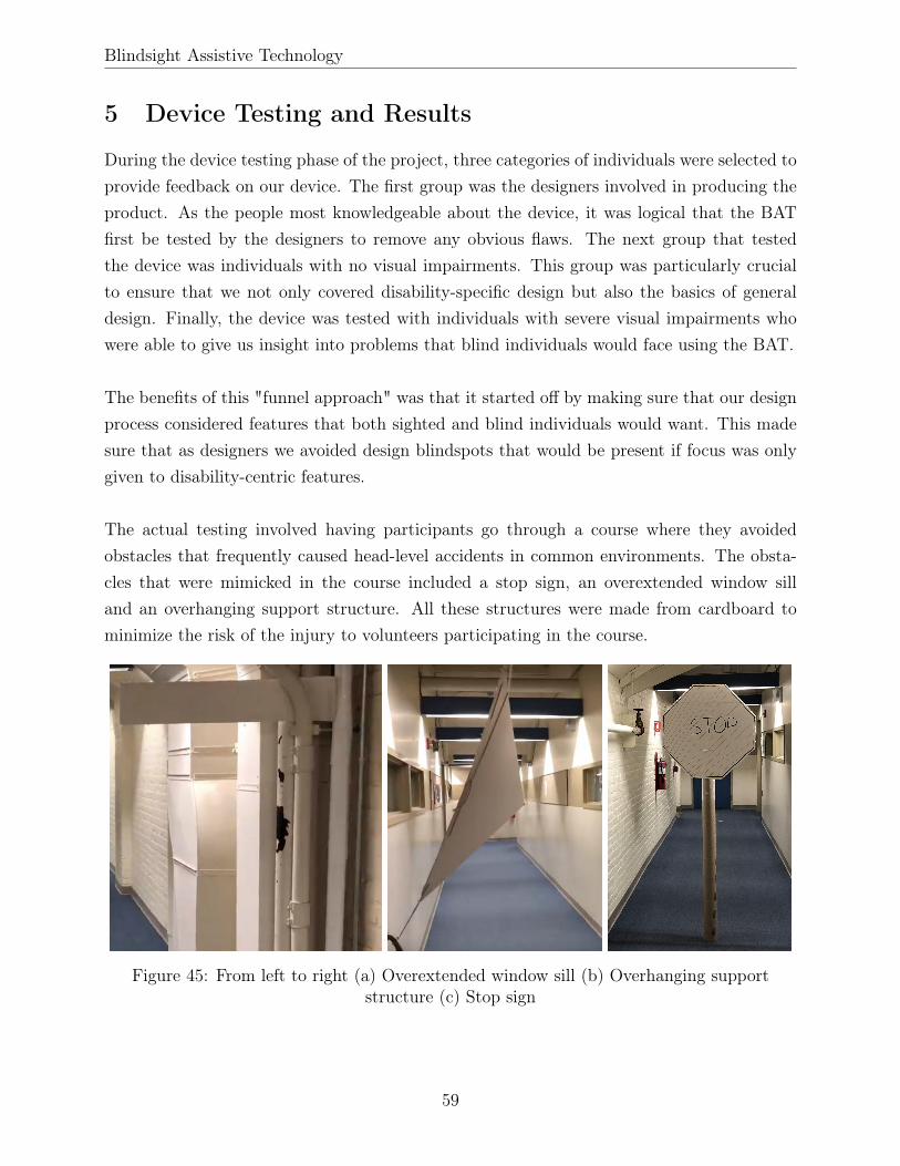
Blindsight Assistive Technology
5 Device Testing and Results
During the device testing phase of the project, three categories of individuals were selected toprovide feedback on our device. The first group was the designers involved in producing theproduct. As the people most knowledgeable about the device, it was logical that the BATfirst be tested by the designers to remove any obvious flaws. The next group that testedthe device was individuals with no visual impairments. This group was particularly crucialto ensure that we not only covered disability-specific design but also the basics of generaldesign. Finally, the device was tested with individuals with severe visual impairments whowere able to give us insight into problems that blind individuals would face using the BAT.
The benefits of this "funnel approach" was that it started off by making sure that our designprocess considered features that both sighted and blind individuals would want. This madesure that as designers we avoided design blindspots that would be present if focus was onlygiven to disability-centric features.
The actual testing involved having participants go through a course where they avoidedobstacles that frequently caused head-level accidents in common environments. The obsta-cles that were mimicked in the course included a stop sign, an overextended window silland an overhanging support structure. All these structures were made from cardboard tominimize the risk of the injury to volunteers participating in the course.
Figure 45: From left to right (a) Overextended window sill (b) Overhanging supportstructure (c) Stop sign
59

Blindsight Assistive Technology
5.1 Testing with Device Designers
Testing was carried out by both designers. The purpose of this testing was to remove anyobvious flaws in the basic functionality of the device. The feedback received is given below.
• Speed of device: A lag was observed in preliminary testing.
• Comfort: Nose bridge had some jagged edges that needed to be sanded down.
• Sensor Functionality: The first sensor behaved as expected, however a noticeable lagwas observed with the second sensor. Also, a random glitch was observed where thedevice would get stuck in a vibration pattern despite changes in the proximity of objectsfrom the user.
5.2 Testing with Individuals Without Visual Impairments
Figure 46: From left to right (a) Sighted individuals participating in course and approachingan overhanging support structure obstacle (b) Sighted individual wearing BAT device
Testing with individuals with no visual impairment proved to be the most beneficial of thethree tests that were conducted with the BAT. For this testing, participants wore a blindfoldand walked through the course with the BAT device on. Two feedback forms were createdprior to testing, a form for organizers to fill out while the participant was walking through thecourse and a form for participants to fill out after walking through the course. These formscan be found in Appendix B. The suggestions received from participants are summarizedbelow.
60

Blindsight Assistive Technology
• Haptic Feedback: A pulsed vibration was successful in alerting users of the proximity ofobjects, however participants did complain that it was difficult to differentiate betweenvibration intensities. The result was that individuals using the BAT had difficultyinterpreting how far the object was from them based on the vibration pattern.
• Sensor Functionality: A wider field-of-view was a recommendation from some partici-pants. The conical shape of the FOV resulted in the device not reporting objects thatwere very close to the face of the individual, but not directly in front of it. This resultedin some participants bumping their shoulder onto the obstacles.
5.3 Testing with Individuals With Visual Impairments
The BAT device was presented to the Regional Manager at the Massachusetts Commissionfor the Blind. As a blind individual, the manager was able to give us very descriptive feedbackabout areas of improvement in the BAT.
• Haptic Feedback: Continuous vibration was not effective because over time the userstarts to drown it out. Pulsed vibrations catch the user’s attention more aggressively.
• Speed of device: A one second lag was observed and noted as unacceptably high.
• Comfort: Nose bridge was not tight enough leading to the glasses sliding down theparticipant’s nose. Sharp edges made the device uncomfortable on the ears.
• Aesthetic: Bulkiness and weight of device were noted as unattractive features.
61

Blindsight Assistive Technology
6 Conclusion and Recommendations
6.1 Recommendations
6.1.1 Processor and Sensing
The team recommends that the next iteration of the device is built on the MSP430 platform.The MSP430 offers many advantages over the AtMega328P, especially when it comes to powerconsumption. The MSP430 also offers a larger number of interrupt enabled pins which wouldallow for a more responsive design of the software. As discussed in the software architecturesection, the processor currently idles for up to 50ms while it waits for each sensor to capturea pulse. With more interrupt enabled pins it could be possible to allow the processor toexecute background tasks such as updating the bands or calculating vibration intensitieswhile the sensors range. It is also recommended that a new sensor is identified. The MB1020is relatively large and this results in difficulties for designing a visually appealing frame forthe glasses. The MB1020 also outputs the pulse information in multiple formats which addsto the 50ms capture time. According to the datasheet, the pulse is captured within 39mS(MaxBotix, 2015). The addition of the RS232 output adds 10ms to the timing sequence. Ina device that must produce close to real-time performance, unnecessary delays such as theseshould be eliminated. Alternatively, the ultrasonic sensor can be replaced altogether with asolid state LiDAR technology which provides a higher resolution of the surroundings. Onelast disadvantage of the ultrasonic sensor, which was identified during testing, is that sincethe detection region is a cone objects disappear from the field of view as the user gets closeto them. This could result in the user’s head avoiding the obstacle while the shoulders stillimpact the obstacle.
6.1.2 Frame Design
There are obvious improvements to be made in the design of the frames, particularly in theattractiveness of the design. With smaller sensors and batteries, the task of designing a morevisually appealing frame will be easier. It is important to strive to eliminate all sharp edgesand to carefully examine the design of the nose bridge since it is the area that brings thegreatest discomfort to the user.
6.1.3 Alternative Form Factors
Next, the team recommends that other form factors for the sensing module are evaluated.This would allow for the device to be more inclusive as it could adapt better to the preferencesof the user. During testing it was found that users who have never used glasses found the
62

Blindsight Assistive Technology
current design exceedingly uncomfortable as would any first time user of optical glasses. Forthese users in particular, a different form factor may be preferable.
6.2 Conclusion
The design of the a proximity sensing device that employs wireless haptic feedback was chal-lenging and the results were mixed. The BAT device met, at a basic level, the specificationsthat were outlined during the conception of the design including wireless feedback, wirelesscharging and an aesthetic-focused design. However, feedback from blind users suggestedthat the device has a long way to go before becoming a viable option for reducing head-level accidents. Further work in developing an effective way to convey obstacle proximitythrough vibrations is crucial in order for Blindsight to meet its intuitive design goals. Thekey takeaway from the design of this mobility aid was the importance of a design centricapproach which has the Seven Principles of Universal Design at its core. Adhering to thisdesign philosophy as well as to the iterative design approach resulted in a device that metthe needs of the target population better than existing products. We recommend that anyteam that desires to develop a disability aid places these design philosophies at the core oftheir development from the conception of the idea to increase the chances of success withtheir device. Most significantly, this project laid the framework for future projects on thedevelopment of disability aids, especially for blind individuals.
63
Blindsight Assistive Technology
References
Alahakone, A. U., & Senanayake, S. M. N. A. (2009). Vibrotactile feedback systems: Currenttrends in rehabilitation, sports and information display. IEEE. doi: 10.1109/AIM.2009.5229741
Ambutech. (n.d.). iGlasses™ Ultrasonic Mobility Aid | Ambutech. Retrieved from https://
ambutech.com/shop-online/iglasses%E2%84%A2-ultrasonic-mobility-aid
Amedi, A., & Hanassy, S. (2010, 12). Infra red based devices for guiding blind and visu-ally impaired persons. USPTO. Retrieved from https://patents.google.com/patent/
US20140055229A1/en?oq=US20140055229A1
Benjamin, J. M. J. (1970, 6). Obstacle detection system for use by blind comprising pluralranging channels mounted on spectacle frames. USPTO. Retrieved from https://patents
.google.com/patent/US3654477A/en?oq=US3654477A
Blindness Statistics. (2018). Retrieved from https://nfb.org/resources/blindness
-statistics
Connell, B. R., Jones, M., Mace, R., Mueller, J., Mullick, A., Ostroff, E., . . . Vanderheiden,G. (1997). Universal Design Principles. Retrieved from https://projects.ncsu.edu/
design/cud/about_ud/udprinciplestext.htm
Dayal, R., Chen, T., & Thackston, A. (2016, 7). Aligning vision-assist device cameras basedon physical characteristics of a user. USPTO. Retrieved from https://patents.google
.com/patent/US20180012376A1/en?oq=US20180012376A1
Djugash, J. M. (2015, 1). Modifying Vision-Assist Device Parameters Based on an Envi-ronment Classification. USPTO. Retrieved from https://patents.google.com/patent/
US20160225287
Farcy, R., Leroux, R., Jucha, A., Damaschini, R., Grégoire, C., & Zogaghi, A. (2019,3). Electronic Travel Aids and Electronics Orientation Aids for Blind People: TechnicalRehabilitation and Everyday Life Points of View.
Grainger. (2015). Personal Protective Equipment (PPE) Size Charts. Re-trieved from https://www.grainger.com/content/qt-personal-protective-equipment
-size-charts-329
64

Blindsight Assistive Technology
Hersh, M. A. (2017). Mobility technologies for blind, partially sighted and deafblind people:Design issues. Springer International Publishing. doi: 10.1007/978-3-319-54446-5\_13
Hoyle, B., & Waters, D. (2010). Mobility AT: The Batcane (UltraCane). In Assistivetechnology for visually impaired and blind people. doi: 10.1007/978-1-84628-867-8\_6
iMerciv. (n.d.). Frequently Asked Questions. iMerciv. Wearable Assistive Technology. Re-trieved from https://imerciv.com/faq.shtml
Jung, K.-K., Chae, Y.-S., & Rhee, J.-K. (2006). Object identification system combinedwith millimeter-wave passive image system and global positioning system (GPS) for theblind - Google Patents. USPTO. Retrieved from https://patents.google.com/patent/
US7336226B2/en?oq=US+7%2c336%2c226+B2+
Kanade, P. M., Sweet, C. W., & Gehlhaar, J. B. (2016, 1). Unmanned aerial vehicle obstacledetection and avoidance. USPTO. Retrieved from https://patents.google.com/patent/
US20170076616A1/en?oq=US20170076616A1
Mahoney, A. (2009). System and method for alerting visually impaired users of nearbyobjects. USPTO. Retrieved from http://ieeexplore.ieee.org/document/799738/ doi:10.1109/38.799738
Manduchi, R., & Kurniawan, S. (2011). Mobility-Related Accidents Experienced by Peo-ple with Visual Impairment. Retrieved from https://pdfs.semanticscholar.org/609b/
3d62282eaa5c2e4a89c803c0b401a789e27d.pdf
Matsuno, N. (2016, 6). Vision-assist devices and methods of calibrating image data ofa vision-assist device. USPTO. Retrieved from https://patents.google.com/patent/
US20170367921A1/en?oq=US20170367921A1
MaxBotix. (2015). LV-MasXonar -EZ Series Datasheet (Tech. Rep.). Retrieved fromhttps://www.maxbotix.com/documents/LV-MaxSonar-EZ_Datasheet.pdf
Nichani, S. (1999, 11). Obstacle detection system. USPTO. Retrieved from https://
patents.google.com/patent/US6678394B1/en?oq=US6678394B1
Nielsen, J. (1993). Iterative user-interface design. Computer , 26 (11), 32–41. doi: 10.1109/2.241424
Pissaloux, E., & Velázquez, R. (2017). Mobility of visually impaired people: Fundamentalsand ICT assistive technologies. doi: 10.1007/978-3-319-54446-5
65

Blindsight Assistive Technology
Poltrock, S. E., & Grudin, J. (1996). E - Interface Development in a Large Organization:An Observational Study**This article is adapted from “Organizational Obstacles to Inter-face Design and Development: Two Participant Observer Studies,” ACM Transactions onComputer-Human Interaction, 1(1)(. In R. B. T. C. Kling & C. S. Edition) (Eds.), (pp.326–347). Boston: Morgan Kaufmann. Retrieved from http://www.sciencedirect.com/
science/article/pii/B9780124150409501159 doi: https://doi.org/10.1016/B978-0-12-415040-9.50115-9
Pullin, G., & Higginbotham, J. (2010). Design Meets Disability. Augmentative and Alter-native Communication. doi: 10.3109/07434618.2010.532926
Pyun, R., Kim, Y., Wespe, P., Gassert, R., & Schneller, S. (2013). Advanced AugmentedWhite Cane with obstacle height and distance feedback. In Ieee international conference onrehabilitation robotics. doi: 10.1109/ICORR.2013.6650358
Sokoler, T., Nelson, L. D., & Pedersen, E. R. (1999, 4). Systems and methods providingtactile guidance using sensory supplementation. USPTO. Retrieved from https://patents
.google.com/patent/US6320496B1/en?oq=US6320496B1
Sound Foresight. (n.d.). About the UltraCane. Retrieved from https://www.ultracane
.com/about_the_ultracane
ST Microelectronics. (2018). VL53L0x Datasheet - Production Data (Tech. Rep.). Retrievedfrom https://www.st.com/resource/en/datasheet/vl53l0x.pdf
Sunu. (n.d.). Sunu Band - FAQs. Retrieved from https://www.sunu.io/en/faqs.html
Terlau Rosanne, T. . H. (n.d.). Step-by-Step: A Guide to Mobility Techniques. Ameri-can Printing House for the Blind. Retrieved from https://tech.aph.org/sbs/04_sbs_lc
_study.html
Visual Impairment. (2016). States News Service. Retrieved from https://advance-lexis
-com.ezproxy.wpi.edu
Ward, K. (2005, 7). Device for providing perception of the physical environment.USPTO. Retrieved from https://patents.google.com/patent/US20070016425A1/en
?oq=US20070016425A1
Withington, D. J., Waters, D. A., Povey, M. J. W., & Hoyle, B. S. (1998, 12). Spa-tial awareness device. USPTO. Retrieved from https://patents.google.com/patent/
US6710706B1/en?oq=US6710706B1
66

Blindsight Assistive Technology
Wong, A. S. T., & Park, C. B. (2017). A Case Study of a Systematic Iterative DesignMethodology and its Application in Engineering Education. Proceedings of the CanadianEngineering Education Association. doi: 10.24908/pceea.v0i0.3148
67

Blindsight Assistive Technology
Appendix
A Sensor Testing Data
All units are in millimeters
VL53L0X Testing:
Table 8: Round 1 VL53L0X Sensor Data Indoors
Figure 47: Comparing round 1 indoors VL53L0X sensor data linear regression line to theline of identity
68

Blindsight Assistive Technology
Table 9: Round 2 VL53L0X Sensor Data Indoors
Figure 48: Comparing round 2 indoors VL53L0X sensor data linear regression line to theline of identity
Table 10: Round 3 VL53L0X Sensor Data Indoors
69

Blindsight Assistive Technology
Figure 49: Comparing round 3 indoors VL53L0X sensor data linear regression line to theline of identity
Temperature during outdoors testing was 1°C
Table 11: Round 1 VL53L0X Sensor Data Outdoors
70

Blindsight Assistive Technology
Figure 50: Comparing round 1 outdoors VL53L0X sensor data linear regression line to theline of identity
MB1020 Testing:
Table 12: Round 1 MB1020 Sensor Data Indoors
71

Blindsight Assistive Technology
Figure 51: Comparing round 1 indoors MB1020 sensor data linear regression line to the lineof identity
Table 13: Round 1 MB1020 Sensor Data Outdoors
Figure 52: Comparing round 1 outdoors MB1020 sensor data linear regression line to theline of identity
72

Blindsight Assistive Technology
B Feedback Forms for Testing with Sighted Individuals
Organizers Feedback Forms:
73

Blindsight Assistive Technology
Participants Feedback Forms:
74

Blindsight Assistive Technology
C Cost of Components
Table 14: Component List
Component Quantity Unit Cost (per 1000) Total CostUltrasonic Sensor - MB1020 2 $17.56 $35.12
Temperature Sensor - TMP36FSZ 1 $1.29 $1.29Potentiometer 20kOhm - 3352T 2 $1.00 $2.00
Tactile Switch - CKN90 1 $0.09 $0.09Transceiver - NRF24L01 3 $2.09 $6.27
NPN BJT - 2N3904 2 $0.04 $0.08Lithium Polymer Battery - LP552 3 $6.95 $20.85
Arduino Pro Mini - ATMega328 3.3V 3 $9.95 $29.85Board Connectors 1 $7.99 $7.99
USB LiPo Charger - MCP73831 3 $6.95 $20.85ST Vibrating Motor - ST3160 2 $1.44 $2.88
Wireless Charging Boards and Coil 2 $9.95 $19.90SMD 100uF Capacitor 3 $0.23 $0.69SMD 1.5kOhm Resistor 2 $0.06 $0.12SMD 1kOhm Resistor 2 $1.44 $2.88
TOTAL $148.09
75


![Blindsight revisited - University Of Marylandfaculty.philosophy.umd.edu/pcarruthers/Weiskrantz...Blindsight revisited Weiskrantz 217 such a residual capacity [22**]. It is of interest](https://static.fdocuments.us/doc/165x107/5e7e0fe3747a981eca0cce39/blindsight-revisited-university-of-blindsight-revisited-weiskrantz-217-such.jpg)


