BLH MODEL 308A, 306, and 304 Installation …cdn.vpg-web.com/documents/3820_tm023c.pdf... 306, and...
13
SYSTEM CALIBRATION TECHNOLOGY BLH MODEL 308A, 306, and 304 Installation Instructions TM023 RevC 6/1/11 Doc 35112
Transcript of BLH MODEL 308A, 306, and 304 Installation …cdn.vpg-web.com/documents/3820_tm023c.pdf... 306, and...
SY
ST
EM
CA
LIB
RA
TIO
N T
EC
HN
OL
OG
Y
BLH
MODEL 308A, 306, and 304
Installation Instructions
TM023
RevC
6/1/11
Doc 35112

NOTICE
BLH makes no representation or warranties of any kind whatsoever with respect to the
contents hereof and specifically disclaims any implied warranties or merchantability or fitness
for any particular purpose. BLH shall not be held liable for errors contained herein or for
incidental or consequential damages in connection with the furnishing, performance, or use
of this publication or its contents.
BLH reserves the right to revise this manual at any time and to make changes in the
contents hereof without obligation to notify any person of such revision or changes.
Call (781) 298-2216 for BLH Field Service
Table of Contents
SECTION 1. Introduction ..................................................................................................................................... 1-1
1.1 General .................................................................................................................................................... 1-1
1.1.1 Model 308A ......................................................................................................................................... 1-1
1.1.2 Model 306............................................................................................................................................ 1-1
1.1.3 Model 304............................................................................................................................................ 1-1
1.2 ENCLOSURE OPTIONS........................................................................................................................ 1-1
1.3 WARRANTY POLICY ............................................................................................................................. 1-1
1.4 FIELD ENGINEERING ........................................................................................................................... 1-2
SECTION 2. Model 308A Installation .................................................................................................................. 2-1
2.1 LOCATION CONSIDERATIONS ........................................................................................................... 2-1
2.2 WIRING CONSIDERATIONS ................................................................................................................ 2-1
2.3 RESISTOR REMOVAL .......................................................................................................................... 2-1
2.4 CLOSING UP .......................................................................................................................................... 2-1
SECTION 3. Model 306 Installation .................................................................................................................... 3-1
3.1 LOCATION CONSIDERATIONS ........................................................................................................... 3-1
3.2 WIRING CONSIDERATIONS ................................................................................................................ 3-1
3.3 CLOSING UP .......................................................................................................................................... 3-1
SECTION 4. Model 304 Installation .................................................................................................................... 4-1
4.1 GENERAL ............................................................................................................................................... 4-1
4.2 LOCATION .............................................................................................................................................. 4-1
4.3 WIRING and CLOSING .......................................................................................................................... 4-1
1-1
SECTION 1. Introduction
1.1 General
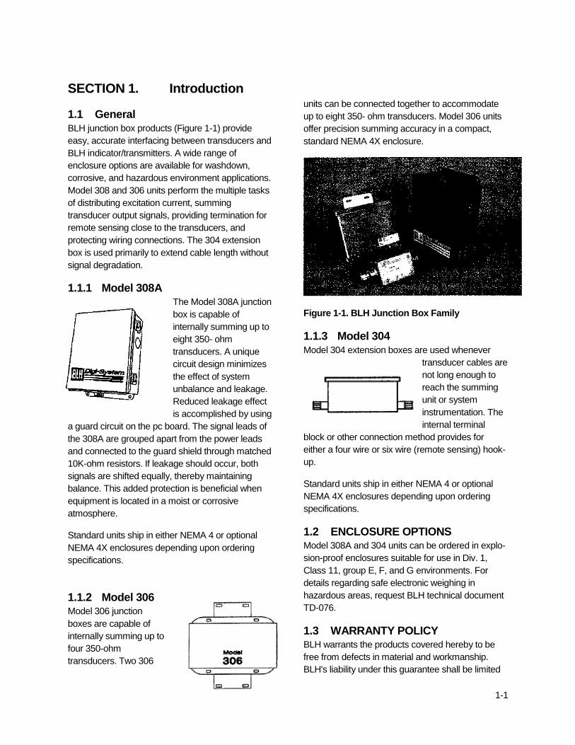
BLH junction box products (Figure 1-1) provide
easy, accurate interfacing between transducers and
BLH indicator/transmitters. A wide range of
enclosure options are available for washdown,
corrosive, and hazardous environment applications.
Model 308 and 306 units perform the multiple tasks
of distributing excitation current, summing
transducer output signals, providing termination for
remote sensing close to the transducers, and
protecting wiring connections. The 304 extension
box is used primarily to extend cable length without
signal degradation.
1.1.1 Model 308A The Model 308A junction
box is capable of
internally summing up to
eight 350- ohm
transducers. A unique
circuit design minimizes
the effect of system
unbalance and leakage.
Reduced leakage effect
is accomplished by using
a guard circuit on the pc board. The signal leads of
the 308A are grouped apart from the power leads
and connected to the guard shield through matched
10K-ohm resistors. If leakage should occur, both
signals are shifted equally, thereby maintaining
balance. This added protection is beneficial when
equipment is located in a moist or corrosive
atmosphere.
Standard units ship in either NEMA 4 or optional
NEMA 4X enclosures depending upon ordering
specifications.
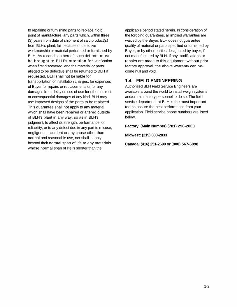
1.1.2 Model 306 Model 306 junction
boxes are capable of
internally summing up to
four 350-ohm
transducers. Two 306
units can be connected together to accommodate
up to eight 350- ohm transducers. Model 306 units
offer precision summing accuracy in a compact,
standard NEMA 4X enclosure.
Figure 1-1. BLH Junction Box Family
1.1.3 Model 304
Model 304 extension boxes are used whenever
transducer cables are
not long enough to
reach the summing
unit or system
instrumentation. The
internal terminal
block or other connection method provides for
either a four wire or six wire (remote sensing) hook-
up.
Standard units ship in either NEMA 4 or optional
NEMA 4X enclosures depending upon ordering
specifications.
1.2 ENCLOSURE OPTIONS Model 308A and 304 units can be ordered in explo-
sion-proof enclosures suitable for use in Div. 1,
Class 11, group E, F, and G environments. For
details regarding safe electronic weighing in
hazardous areas, request BLH technical document
TD-076.
1.3 WARRANTY POLICY BLH warrants the products covered hereby to be
free from defects in material and workmanship.
BLH's liability under this guarantee shall be limited
1-2
to repairing or furnishing parts to replace, f.o.b.
point of manufacture, any parts which, within three
(3) years from date of shipment of said product(s)
from BLH's plant, fail because of defective
workmanship or material performed or furnished by
BLH. As a condition hereof, such defects must
be brought to BLH's attention for verification
when first discovered, and the material or parts
alleged to be defective shall be returned to BLH if
requested. BLH shall not be liable for
transportation or installation charges, for expenses
of Buyer for repairs or replacements or for any
damages from delay or loss of use for other indirect
or consequential damages of any kind. BLH may
use improved designs of the parts to be replaced.
This guarantee shall not apply to any material
which shall have been repaired or altered outside
of BLH's plant in any way, so as in BLH's
judgment, to affect its strength, performance, or
reliability, or to any defect due in any part to misuse,
negligence, accident or any cause other than
normal and reasonable use, nor shall it apply
beyond their normal span of life to any materials
whose normal span of life is shorter than the
applicable period stated herein. In consideration of
the forgoing guarantees, all implied warranties are
waived by the Buyer, BLH does not guarantee
quality of material or parts specified or furnished by
Buyer, or by other parties designated by buyer, if
not manufactured by BLH. If any modifications or
repairs are made to this equipment without prior
factory approval, the above warranty can be-
come null and void.
1.4 FIELD ENGINEERING Authorized BLH Field Service Engineers are
available around the world to install weigh systems
and/or train factory personnel to do so. The field
service department at BLH is the most important
tool to assure the best performance from your
application. Field service phone numbers are listed
below.
Factory: (Main Number) (781) 298-2000
Midwest: (219) 838-2833
Canada: (416) 251-2690 or (800) 567-6098
2-1
SECTION 2. Model 308A Installation
2.1 LOCATION CONSIDERATIONS Install the 308A junction box within reach of all
transducer cables if possible. If a transducer cable
does not reach the 308A, consider using a 304 box
and BLH supplied extension cable.
The installation location should be reasonably
clean and moisture free. Mount NEMA 414X units
in accordance with dimensions provided in Figure
2-1 and explosion-proof units according to Figure
2-2.
NOTE: Load cells installed in Div.1I hazardous
locations must be protected with intrinsic safety
barriers. Explosion-proof enclosures are not
required in intrinsically safe systems.
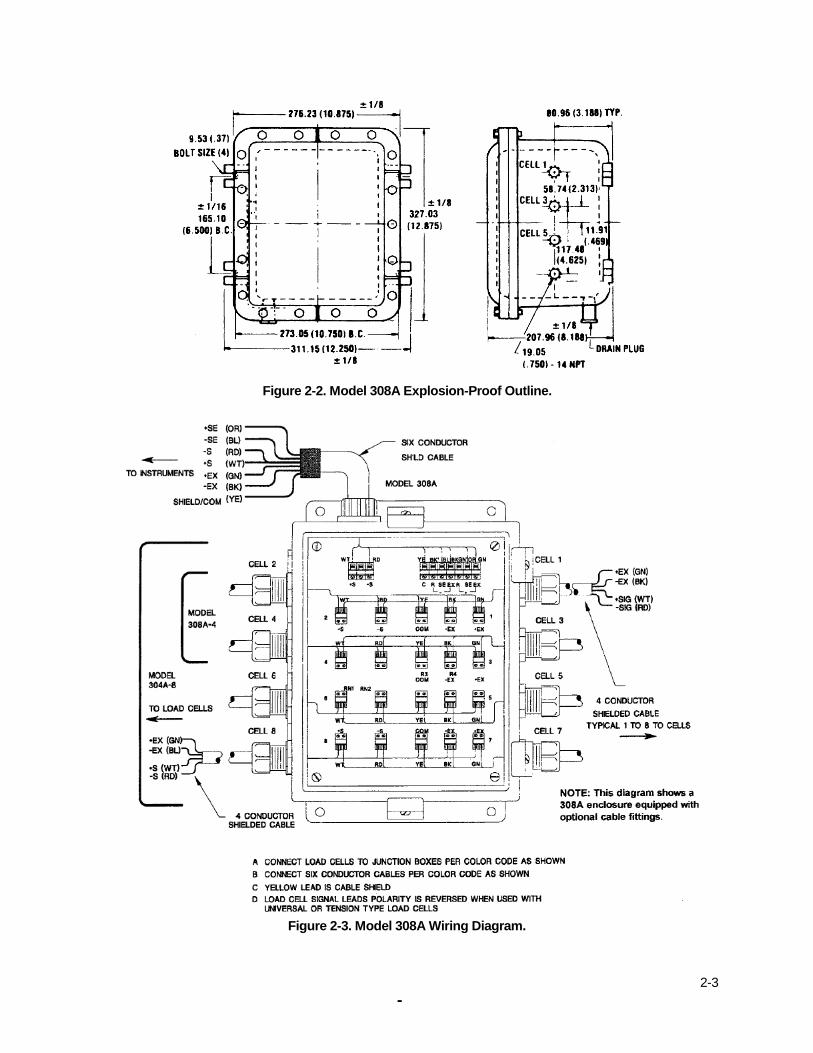
2.2 WIRING CONSIDERATIONS After the unit is mounted, remove the plastic
enclosure hole plugs and replace with appropriate
conduit fittings. Trim the tinned lead ends of the
transducer cables to 1/4" (maximum). Connect
transducer leads as shown in the Figure 2-3 wiring
diagram. Before tightening terminal screws, make
certain that exposed transducer lead ends are
completely free of insulation. Good lead contact
prevents needless trouble shooting during system
start-up. After installing all transducers, connect the
leads of the 6 conductor instrument cable as
shown in Figure 2-3 (next page).
2.3 RESISTOR REMOVAL Some BLH indicators/transmitters feature mV/V
calibration. In order for mV/V calibration to
function properly, 10K-ohm resistors R1 and R2
must be removed. Figure 2-4 (next page) shows
the location of these two components. Note,
however, that the 'guard' circuit is no longer
effective when these resistors are disconnected
(see paragraph 1.1.1).
2.4 CLOSING UP After installation and wiring is complete, tighten all
cable entry/exit fittings and then close and tighten
the 308A junction box cover.

2-2
Figure 2-1. Model 308A NEMA Enclosure Outline
2-3
II
Paae
Figure 2-2. Model 308A Explosion-Proof Outline.
Figure 2-3. Model 308A Wiring Diagram.

2-4
Figure 2-4. R1 and R2 Resistor Locations.
3-1
SECTION 3. Model 306 Installation
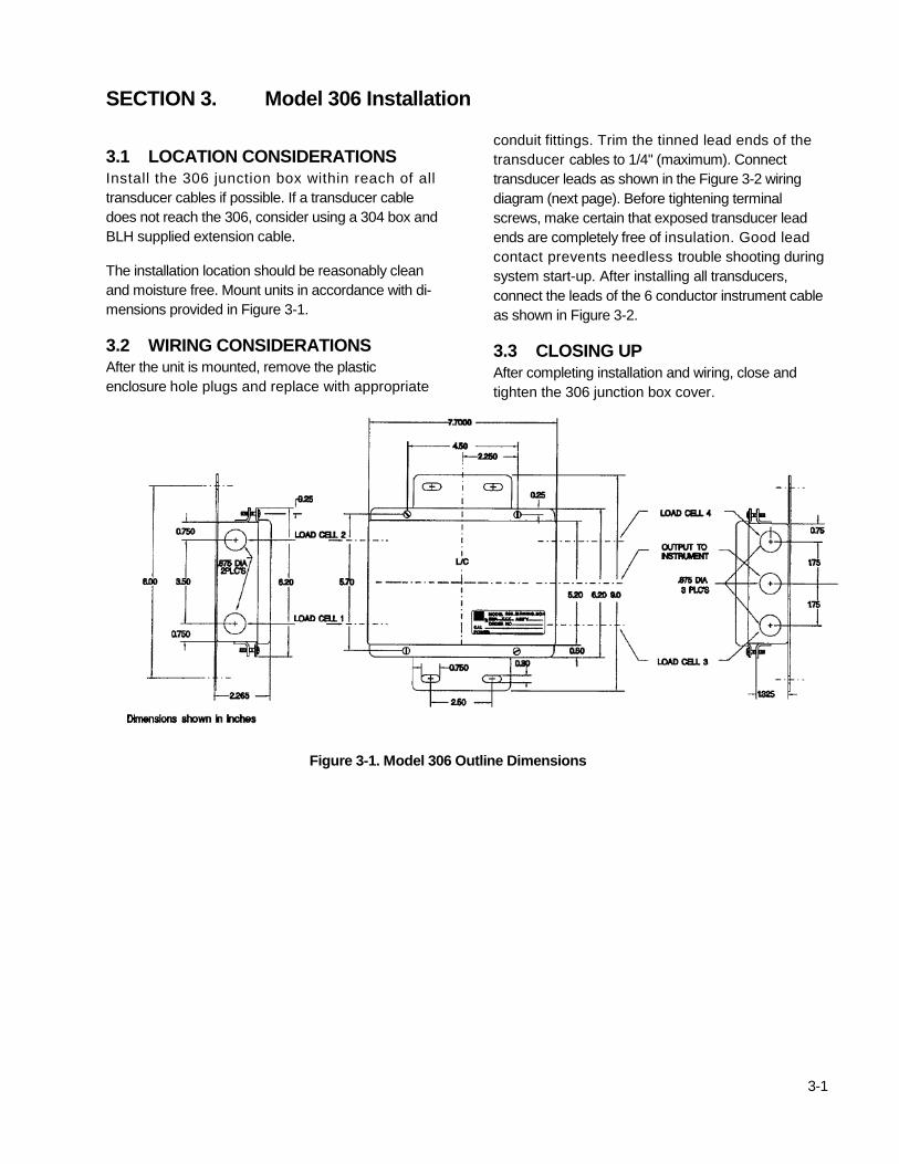
3.1 LOCATION CONSIDERATIONS
Install the 306 junction box within reach of all
transducer cables if possible. If a transducer cable
does not reach the 306, consider using a 304 box and
BLH supplied extension cable.
The installation location should be reasonably clean
and moisture free. Mount units in accordance with di-
mensions provided in Figure 3-1.
3.2 WIRING CONSIDERATIONS After the unit is mounted, remove the plastic
enclosure hole plugs and replace with appropriate
conduit fittings. Trim the tinned lead ends of the
transducer cables to 1/4" (maximum). Connect
transducer leads as shown in the Figure 3-2 wiring
diagram (next page). Before tightening terminal
screws, make certain that exposed transducer lead
ends are completely free of insulation. Good lead
contact prevents needless trouble shooting during
system start-up. After installing all transducers,
connect the leads of the 6 conductor instrument cable
as shown in Figure 3-2.
3.3 CLOSING UP
After completing installation and wiring, close and
tighten the 306 junction box cover.
Figure 3-1. Model 306 Outline Dimensions

4-2
Figure 3-2. Model 306 Wiring Diagram.
4-1
SECTION 4. Model 304 Installation
4.1 GENERAL
Model 304 extension junction boxes are used when the
transducer cable is not long enough to connect directly to
the instrument in a single-cell system or the summing
junction box in multi-cell systems. The 304 box has
terminals for interfacing the 4-wire transducer cable with a
6-wire cable and for remote sensing close to the
transducer location.
Standard 304 boxes are zinc plated or optional stainless
steel depending upon ordering specifications. Optional
explosion-proof units are suitable for use in Div. 1, Class
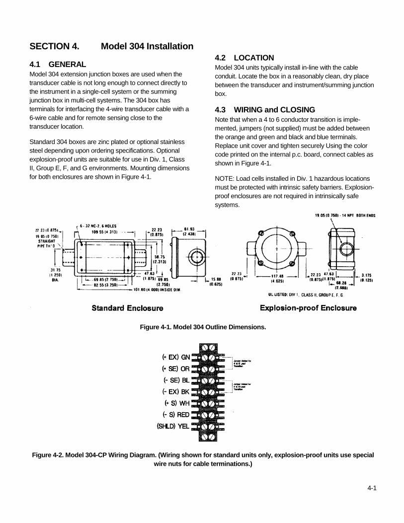
II, Group E, F, and G environments. Mounting dimensions
for both enclosures are shown in Figure 4-1.
4.2 LOCATION Model 304 units typically install in-line with the cable
conduit. Locate the box in a reasonably clean, dry place
between the transducer and instrument/summing junction
box.
4.3 WIRING and CLOSING
Note that when a 4 to 6 conductor transition is imple-
mented, jumpers (not supplied) must be added between
the orange and green and black and blue terminals.
Replace unit cover and tighten securely Using the color
code printed on the internal p.c. board, connect cables as
shown in Figure 4-1.
NOTE: Load cells installed in Div. 1 hazardous locations
must be protected with intrinsic safety barriers. Explosion-
proof enclosures are not required in intrinsically safe
systems.
Figure 4-1. Model 304 Outline Dimensions.
Figure 4-2. Model 304-CP Wiring Diagram. (Wiring shown for standard units only, explosion-proof units use special
wire nuts for cable terminations.)

BLH
3 Edgewater Drive,
Norwood, MA 02062 U.S.A
Phone (781) 298-2200
Fax (781) 762-3988
www.vishaypg.com