Blaster 2 Assembly Guide - HyperFlight.co.uk 2 Assembly Guide.pdf · HyperFlight.co.uk Blaster 2...
11
Blaster 2 & 2e Assembly Guide from HyperFlight.co.uk 123 Radford Road Leamington Spa Warwickshire UK CV31 1LG www.HyperFlight.co.uk [email protected] © 2009 HyperFlight Revision 5, 1/05/09 Blaster 2 Assembly Guide R5.odt
Transcript of Blaster 2 Assembly Guide - HyperFlight.co.uk 2 Assembly Guide.pdf · HyperFlight.co.uk Blaster 2...

Blaster 2 & 2e Assembly Guidefrom
HyperFlight.co.uk
123 Radford RoadLeamington SpaWarwickshire UK CV31 [email protected]
© 2009 HyperFlight
Revision 5, 1/05/09Blaster 2 Assembly Guide R5.odt
HyperFlight.co.uk Blaster 2 Assembly Guide
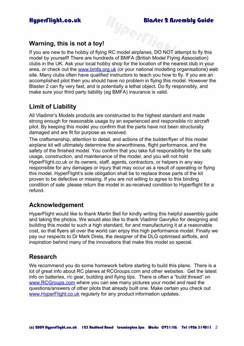
Warning, this is not a toy!If you are new to the hobby of flying RC model airplanes, DO NOT attempt to fly this model by yourself! There are hundreds of BMFA (British Model Flying Association) clubs in the UK. Ask your local hobby shop for the location of the nearest club in your area, or check out the www.bmfa.org.uk (or your national modelling organisations) web site. Many clubs often have qualified instructors to teach you how to fly. If you are an accomplished pilot then you should have no problem in flying this model. However the Blaster 2 can fly very fast, and is potentially a lethal object. Do fly responsibly, and make sure your third party liability (eg BMFA) insurance is valid.
Limit of LiabilityAll Vladimir’s Models products are constructed to the highest standard and made strong enough for reasonable usage by an experienced and responsible r/c aircraft pilot. By keeping this model you confirm that the parts have not been structurally damaged and are fit for purpose as received. The craftsmanship, attention to detail, and actions of the builder/flyer of this model airplane kit will ultimately determine the airworthiness, flight performance, and the safety of the finished model. You confirm that you take full responsibility for the safe usage, construction, and maintenance of the model, and you will not hold HyperFlight.co.uk or its owners, staff, agents, contractors, or helpers in any way responsible for any damages or injury that may occur as a result of operating or flying this model. HyperFlight’s sole obligation shall be to replace those parts of the kit proven to be defective or missing. If you are not willing to agree to this binding condition of sale please return the model in as-received condition to Hyperflight for a refund.
AcknowledgementHyperFlight would like to thank Martin Bell for kindly writing this helpful assembly guide and taking the photos. We would also like to thank Vladimir Gavrylko for designing and building this model to such a high standard, for and manufacturing it at a reasonable cost, so that flyers all over the world can enjoy this high performance model. Finally we pay our respects to Dr Mark Drela, the designer of the DLG optimised airfloils, and inspiration behind many of the innovations that make this model so special.
ResearchWe recommend you do some homework before starting to build this plane. There is a lot of great info about RC planes at RCGroups.com and other websites. Get the latest info on batteries, r/c gear, building and flying tips. There is often a “build thread” on www.RCGroups.com where you can see many pictures your model and read the questions/answers of other pilots that already built one. Make certain you check out www.HyperFlight.co.uk regularly for any product information updates.
(c) 2009 HyperFlight.co.uk 123 Radford Road Leamington Spa Warks CV311LG Tel 1926 314011 2

HyperFlight.co.uk Blaster 2 Assembly Guide
Parts ListWing (1 piece).Fuselage pod & boom.Nosecone.AMT - horizontal stabiliser.Fin/rudder - vertical stab.0.7mm carbon pushrods and PTFE outers.Accessories bag containing the AMT V mount, horns, and pushrod parts shown opposite.These Instructions.
R/C FunctionsLeft Aileron (Flaperon)Right Aileron (Flaperon)ElevatorRudderTo maximise the model's potential a computer radio is highly recommended.
Suggested R/CWing servos: Vigor VS-12m or Ripmax SD150/Dymond D60 Tail servos: Ripmax SD100/Dymond D47 Receiver: Schulze 535 or other small 5 channel receiverBattery: 300-400mAh NiMH or 2S LiPo with 5V regulator
(see the alarm regulators for sale on www.hyperflight.co.uk)
Model SpecificationsWingspan: 1.5m (59 in)Wing Area: 24 dm2 (372 sq in)Target Weight: From 290g (10.2 oz)Wing Loading: 12.1g/dm2 (4.0 oz/sq ft)Airfoils: Ag 45 ct-o2, Ag46 ct-02 , AG 47 ct-02
Note these instruction are for a right handed launcher, with the launching winglet on the left wing. For left handed launchers (with winglets on the right tip) please reverse any left/right instructions - the rudder horn should be on the left side of the rudder.
Also please test to ensure that any cyano glue used does not melt the foam internal structure when gluing components.
(c) 2009 HyperFlight.co.uk 123 Radford Road Leamington Spa Warks CV311LG Tel 1926 314011 3

HyperFlight.co.uk Blaster 2 Assembly Guide
Blaster 2 Assembly Guideby Martin Bell
AMT (All Moving Tail) & Fin/Rudder AssemblyFix wing to fuselage assembly using 3mm set screws supplied. Be careful when tightening these single slot head screws so as not to let the screwdriver slip off the screw head as the wing can be easily damaged by a wandering screwdriver head!
HINT: Replacing the supplied screws with cross-head or Allen key headed screws is an option you may like to consider if you intend removing and re-fitting the wing panel for transport of the model.
HINT: At this stage it is a good idea to make sure that the flaperons clear the tail boom properly when they are moved downward. Any minor adjustment required is easily done by elongation the holes in the wing pylon mount a tiny amount with a small round needle file.
Fix AMT (All Moving Tail-plane) to the V-mount using the special screw supplied.
Slide AMT / V-mount assembly on to tail boom and adjust position until rear of AMT is approximately 5mm from front of fin slot in the boom AND perfectly horizontal in relation the mounted wing panel.
Very carefully apply a very small amount of thin cyano adhesive to the V-Mount at the boom joint. Be very careful not to allow the cyano to run up the V-mount and into the precision bearing assembly that carries the tail-plane.
Remove the tail-plane and the wing panel and place to one side.
HINT: It is a good idea to keep all panels in their foam bags when not actually working on them. To make it MUCH easier to remove from and place in the foam bag, simply place a small length of masking tape between the trailing edges of the flaperons at their centre position.
Trial fit the fin / rudder assembly to the rear of the boom leaving 70mm of the fin below the bottom of the tail boom. When happy with the positioning, tape or hold the fin at precisely 90 degrees to the AMT and at 90 degrees to the top of the boom before carefully applying thin cyano or epoxy adhesive to the joint. If using cyano make sure it does not run onto the inner foam section of the fin. When dry remove the AMT and place to one side in its foam cover.
HINT: If in doubt at all about using cyano in any part of the assembly, 5 minute epoxy is certainly an option, at the cost of a small amount of extra weight and the need the hold components in place for 5 minutes when the adhesive sets. Another alternative would be to use “Foam Safe” cyano.
(c) 2009 HyperFlight.co.uk 123 Radford Road Leamington Spa Warks CV311LG Tel 1926 314011 4

HyperFlight.co.uk Blaster 2 Assembly Guide
Rudder & AMT Controls Snakes
Wrap a layer of masking tape around the boom to cover an area approximately 70mm in front of the front edge of the AMT V-mount. Mark a spot 55mm in front of the V-mount, exactly on top of the boom in alignment with the AMT control horn. Similarly place some masking tape around the boom immediately behind the front RIGHT HAND side of the fin and mark a spot on the boom about 3mm back from the front of the fin and at a position on the boom exactly 90 degrees to the fin. CAREFULLY drill a 2.5mm hole at both positions. Remove the masking tape, and then elongate each hole so that the outer tubes for the carbon control rods exit the boom at right angles to, and in direct alignment with their respective control horns on the AMT V-mount and the rudder horn, which is still to be fitted.
When satisfied with the fit of the push rod tubes, fit them in position, leaving short lengths of both tubes protruding from the boom. When passing the tubes down the inside of the boom, MAKE SURE that they exit in the correct place in the nose of the model to fit in with your proposed servo installation. Carefully secure the tubes in position with a cyano and then carve off the excess with a scalpel blade to leave them flush with the surface of the tail boom.
Place a piece of masking tape on the rudder in line with the centre of the tail boom and mark the position of the rudder control horn. Carefully cut a slot in the rudder at the position marked with a sharp scalpel blade, then remove the masking tape and fix the rudder horn in place using a very small amount of epoxy adhesive or FOAM SAFE cyano. The next step is to fit two of the four small steel push rod ends supplied to the carbon push rods. This can be done using cyano, in which case it must be done quickly to ensure that the carbon push rods fit right into the push rod ends before the cyano sets. Before installing the push rods into their tubes, (from the rear of the boom), make 90 degree bends in the thin solid section of the push rod ends ready to fit into their respective control horns.
Wing Panel Preparation and Servo Fitting
Be very careful when working on the Wing Panel not to damage the upper or lower surfaces. Always ensure that the wing is resting on a soft, resilient material, (such as the foam bag that the wings came in), at all times. There is no doubt that the vast majority of minor damage to this type of model occurs during build and later through careless handling.
Cut out pre-defined servos access holes in underside of wing using a sharp scalpel blade and steel straight edge. Make sure that you leave a 3mm lip, which will enable the servos covers to be fitted flush with the underside of the wing when the servo installation is complete. It is ALWAYS a good idea to place masking tape on any panel before cutting as this helps prevent the tool being used slipping out of position and damaging the surrounding surface.
(c) 2009 HyperFlight.co.uk 123 Radford Road Leamington Spa Warks CV311LG Tel 1926 314011 5

HyperFlight.co.uk Blaster 2 Assembly Guide
Prepare your selected wing servos by removing the mounting lugs and wrapping in two layers of masking tape. Fit and adjust the servo output arms to achieve required travel and trial fit to ensure position of servos is correct relative to the re-enforced areas in the flaperons that take the control horns. Also make sure that the servo output arm sweep is adequate. Ensure that servos are in their neutral position before securing in place with 5-minute epoxy. Make sure that the side of the servo butts up against the main spar. (This is to ensure that the main servo loads are transmitted into the spar and not the wing skin.)
Use masking tape to cover the re-enforced areas on the flaperons, mark out and cut the slots for the control horns, exactly in line with the servo output arms. Secure the control horns in place with epoxy adhesive. Make up control linkages by cutting the long wire in half. Bend the halves into L shapes. Trim the carbon tube if necessary.Centre the servo, test fit the linkage, and cyano the wire long L sides into the carbon tube. Fix the linkage in place with keepers or short pieces of tubing cyanoed in place. Ensure the underside of wing/flaperons is perfectly in line in neutral servos position.
Radio, Battery and Regulator Installation
There is so much room on the mounting plate in the sheath nose and it is so accessible, that a wide variation of installation possibilities exist, some of which are shown in the photographs below. Whatever system or installation you decide upon, remember to try and arrange the component parts so that the minimum of nose weight is required to balance the model at 78mm back from the leading edge of the wing panel.
Use an appropriately short arm on the elevator servo so that is does not have to be rated down. If this is not done a glitch could cause extreme AMT pushrod deflection, which could break the 0.7mm carbon pushrod where the wire is attached. Ensure there are no stress raisers in the pushrod/wire fixing. Make an opening in the bottom of the wing for the servo wiring. Either use extension leads or solder up a wiring harness using a suitable plug and socket – a Deans Micro 4 pin plug in this case.
Settings GuideCentre of Gravity DLG: 78mm-82mm from leading edge of wing under pylon mount.Electric: 73mm-79mm from wing leading (due to shorter boom).
Elevator (AMT) Travel12 mm up, 12mm down (at rear of AMT).Initial setting height of AMT trailing edge above top of boom.Cruise 22.5 mmLaunch 22.0 mm
(c) 2009 HyperFlight.co.uk 123 Radford Road Leamington Spa Warks CV311LG Tel 1926 314011 6

HyperFlight.co.uk Blaster 2 Assembly Guide
Rudder Travel25 mm left & rightNo rudder offset required on launch
Ailerons (Flaperons)Up +20 mm / down -9 mm (extreme throw for advanced user, beginners use less)Cruise – Lower surface of flaperons down 2 degreesSpeed – Lower surface of flaperons down 0.5 degrees.Launch – Lower surface of flaperons reflexed up 0.5 degrees.Thermal – Lower surface of flaperons down 6 degrees.Landing – Lower surface of flaperons down 45 degrees. Mix in progressive down elevator, approx 6mm at 20 deg, reducing to approx 4mm at 45 deg.Use the enclosed templates to setup the flaperon positions accurately. Alternative faster settings recommended by Simon Jones (measured in mm with a straight edge underneath the wing in line with the servo/control horn) are:Launch & Speed = -3mm, Cruise & Normal Thermal= -2mm, Weak Thermal = 0mm.
TrimmingCheck for long flat glide from a fast hand launch in Launch Mode. Only very minor AMT trim adjustment should be needed. If the rudder and flaperons have been set as above, then NO adjustment should be required to these control surfaces. Gradually increase launch speed to a hard “javelin” style launch. Make minor adjustments to AMT launch trim as required until model climbs at about 30 to 40 deg from launch. At this stage it is safer to work towards a trim where the launch angle gradually increases from launch. ONLY NOW should you try the first Discus launch.
Need more information?Try these Internet links and check out the July 2008 issue of Radio Control Model World for the Blaster 2 DLG review.144 more Blaster 2 DLG Build Pictures - http://www.photobox.co.uk/album/765608159 more Blaster 2 DLG Flying Pictures - http://www.photobox.co.uk/album/765575638 more Blaster 2 E Build Pictures - http://www.photobox.co.uk/album/7692097Blaster 2 Thread on FlyQuiet Forum - http://www.flyquiet.co.uk/smf/index.php?topic=1037.0Blaster 2 Electric Thread - http://www.flyquiet.co.uk/smf/index.php?topic=1079.0Blaster 2 Electric Flying Video 1 - http://www.youtube.com/watch?v=Lg7wRCr_XxkBlaster 2 Electric Flying Video 2 - http://www.youtube.com/watch?v=AnCUPFbePNQBlaster 2 – Manufacturers web site - http://airplane-model.com/blaster2.html
(c) 2009 HyperFlight.co.uk 123 Radford Road Leamington Spa Warks CV311LG Tel 1926 314011 7

HyperFlight.co.uk Blaster 2 Assembly Guide
A few build pictures to help you on your way!
(c) 2009 HyperFlight.co.uk 123 Radford Road Leamington Spa Warks CV311LG Tel 1926 314011 8
Fitting Fin/Rudder to Tail Boom
AMT Mount and Push Rod Tubes
Tape between Flaperon Halves
Fitting Fin/Rudder to Tail Boom
Cut out pre defined servo accesses Cut lugs off wing servos.
Servos wrapped and wing wiring Flaperon Links & Horn installed
Easiest way to cut slots for horns.
Possible Servo Installation 1
Possible Servo & Battery Position
Receiver & Regulator Positions
Possible Servo / Regulator Inst 2
Receiver on Underside of Mount.

HyperFlight.co.uk Blaster 2 Assembly Guide
Flaperon Templates
Cut the templates from card and use them to position the flaperon for the following flight modes.
1) CRUISE flight mode.
2) SPEED flight mode for best wind penetration.
(c) 2009 HyperFlight.co.uk 123 Radford Road Leamington Spa Warks CV311LG Tel 1926 314011 9

HyperFlight.co.uk Blaster 2 Assembly Guide
3) Discus Launch mode.
4) Maximum THERMAL flight mode.
The template can also be downloaded from www.hyperflight.co.uk/getfile.asp?code=BLASTER-2&code2=3and printed directly onto card.
(c) 2009 HyperFlight.co.uk 123 Radford Road Leamington Spa Warks CV311LG Tel 1926 314011 10

HyperFlight.co.uk Blaster 2 Assembly Guide
Electric Blaster 2 Addendum
Tail Assembly & Servo InstallationBuild the wings just like the Blaster 2 glider. Trial bolt the wings to the fuselage. Bolt the tailplane to the V mount and slip it onto the tail boom. Glue the fin/rudder to the rudder/servo mount. Trial fit the rudder/servo mount at the extreme rear of the boom, and mark where the V mount should fit for the tailplane to just clear the fin. Remove the rudder/servo mount and glue the V mount in place using epoxy or cyano. Ensure the tailplane is horizontally aligned with the wing before the glue sets. Remove the wing and tailplane.
Extend the Ripmax SD100/Dymond D47 tail servo leads using lightweight wire – old PC mouse cables often have suitable lightweight flexible cores. Wrap the tail servos in masking tape offset as in the photos. Use just enough layers to make the servos a good close fit in the rudder/servo mount. Remove the servo output arms and position the servos as a unit in the correct position in the rudder/servo mount. Then measure and mark out, on the outside of the mount, the position of the servo output arms and carefully cut the required slots in the mount big enough to be able to insert the arms from the outside, after fixing the servos in place.
After double checking, remove the servos, spread a very small amount of 5 minute epoxy on the masking tape wrapping and glue the servos in place inside the rudder/servo mount. (By using masking tape it should be possible to remove the servos without too much difficulty if this ever becomes necessary.) Connect the servos to the receiver and ensure they are centered. Maneuver the servo output arms into position on their respective servos. It is then quite easy to fit the servo arm retaining screws from the underside of the fin. Finally lightly glue the fin/servo assembly into place on the boom, routing the servo wires through the boom to the receiver in the pod. Before the glue sets ensure the fin is at 90 degrees to the tailplane and wing.
See www.hyperflight.co.uk for electric power train suggestions. Note you may have to add ballast in the tail to obtain the correct center of gravity.(c) 2009 HyperFlight.co.uk 123 Radford Road Leamington Spa Warks CV311LG Tel 1926 314011 11