Blast Retrofit of a RC Frame Building in a Petrochemical ... · PDF fileBlast Retrofit of a RC...
12
Blast Retrofit of a RC Frame Building in a Petrochemical Facility – a Case Study Marlon Bazan 1 , Chuck Oswald 1 , Andre Garner 2 1 Protection Engineering Consultants, 4203 Gardendale, Suite C112, San Antonio, TX 78229, [email protected]; [email protected] 2 Garner Consulting Group, 100 Commons Rd., Ste. 7-302, Dripping Springs, TX 78620, [email protected] ABSTRACT This paper presents a case study of the design of a blast-resistant retrofit for a control room at a petrochemical refinery in South Texas. The control room is a 1-story reinforced concrete frame building with masonry walls and steel roof deck supported by open-web steel joists. The building was analyzed and retrofits were designed for the design blast loads specified in an existing siting study. The design of the blast retrofit was completed in two stages: the initial concept study and the final design of the selected blast upgrade. The concept study consisted of the preliminary design of three different blast upgrades for the exterior masonry walls: attached HSS posts or FRP (fiber reinforced polymer) and an exterior shield wall system. After an assessment of the estimated construction costs and operational considerations, the shield wall system was selected by the building owner for final design. This paper discusses the concept level design of the upgrade options and the final design of the selected upgrade. In addition, the paper also discusses the upgrade required for the roof diaphragm. The design work was completed in March 2012. INTRODUCTION Buildings at petrochemical facilities need to be able to withstand effects of accidental explosions that can occur in process plants. Depending on the building function, the building may be required to satisfy different structural performance goals, including protection of personnel and critical equipment, and it may need to remain operational during an accidental explosion event. The design blast loads are usually determined through a site specific study which identifies and quantifies the explosion hazards in the plant and associated worst case blast loads on the building. Changes in building occupancy, building function, process hazards, or corporate policy, among other actions, can trigger or change blast-resistance requirements for existing buildings that may not have been designed to resist the specified blast loads. When required, the blast capacity of these buildings can be increased using different available structural retrofits. A number of options are available to upgrade the blast capacity of an existing building. The choice of an upgrade option is generally based on the applied blast loads, characteristics of the existing structural component makeup, cost considerations, implementation approach around current operations, and building functionality requirements. The design of blast resistant retrofits to existing buildings can be subject to many limiting factors not typically applicable for
-
Upload
truongkien -
Category
Documents
-
view
221 -
download
3
Transcript of Blast Retrofit of a RC Frame Building in a Petrochemical ... · PDF fileBlast Retrofit of a RC...
Blast Retrofit of a RC Frame Building in a Petrochemical Facility – a Case
Study
Marlon Bazan 1, Chuck Oswald 1, Andre Garner 2 1 Protection Engineering Consultants, 4203 Gardendale, Suite C112, San Antonio, TX 78229, [email protected]; [email protected] 2 Garner Consulting Group, 100 Commons Rd., Ste. 7-302, Dripping Springs, TX 78620, [email protected]
ABSTRACT
This paper presents a case study of the design of a blast-resistant retrofit for a control room at a petrochemical refinery in South Texas. The control room is a 1-story reinforced concrete frame building with masonry walls and steel roof deck supported by open-web steel joists. The building was analyzed and retrofits were designed for the design blast loads specified in an existing siting study. The design of the blast retrofit was completed in two stages: the initial concept study and the final design of the selected blast upgrade. The concept study consisted of the preliminary design of three different blast upgrades for the exterior masonry walls: attached HSS posts or FRP (fiber reinforced polymer) and an exterior shield wall system. After an assessment of the estimated construction costs and operational considerations, the shield wall system was selected by the building owner for final design. This paper discusses the concept level design of the upgrade options and the final design of the selected upgrade. In addition, the paper also discusses the upgrade required for the roof diaphragm. The design work was completed in March 2012.
INTRODUCTION
Buildings at petrochemical facilities need to be able to withstand effects of accidental explosions that can occur in process plants. Depending on the building function, the building may be required to satisfy different structural performance goals, including protection of personnel and critical equipment, and it may need to remain operational during an accidental explosion event. The design blast loads are usually determined through a site specific study which identifies and quantifies the explosion hazards in the plant and associated worst case blast loads on the building.
Changes in building occupancy, building function, process hazards, or corporate policy, among other actions, can trigger or change blast-resistance requirements for existing buildings that may not have been designed to resist the specified blast loads. When required, the blast capacity of these buildings can be increased using different available structural retrofits. A number of options are available to upgrade the blast capacity of an existing building. The choice of an upgrade option is generally based on the applied blast loads, characteristics of the existing structural component makeup, cost considerations, implementation approach around current operations, and building functionality requirements. The design of blast resistant retrofits to existing buildings can be subject to many limiting factors not typically applicable for

2
the design of new blast resistant buildings. The engineer must consider the capacity of existing framing components to resist increased reaction loads from retrofitted wall and roof components, limitations on the achievable connection strengths between retrofitted and existing components, limits on available space for retrofits and accessibility for construction equipment, aesthetic considerations, and potential loss of building operational capability during and after construction.
This paper presents a case study of the design of a blast retrofit for an existing building at a petrochemical refinery located in South Texas. The upgrades were designed by Protection Engineering Consultants (PEC) and the cost estimates and construction drawings were developed by Garner Consulting Group (GCG). The design process had two phases, including an initial phase where building damage to the design blast loads was calculated and preliminary upgrade design was performed for all components with heavy damage or failure. Since only limited drawings were available, field measurements were taken of the structure and all appurtenances on the exterior of the facility were mapped. Concept-level design was performed for three different upgrade options for the walls and corresponding cost estimates were developed for the building upgrade. The second phase consisted of final design of the selected upgrade option and preparation of construction documents. This paper discusses the concept-level design of the upgrade options and the final design of the upgrade option selected by the building owner.
BUILDING AND BLAST LOAD DESCRIPTION
The building requiring upgrade is a 1-story, 96-ft long by 60-ft wide, reinforced concrete frame building with double wythe masonry walls (see Figure 1). The gravity and lateral force resisting system consists of a perimeter RC moment frame, with 12-in by 14-in columns and 9-in by 44-in deep beams. In addition, a 12-in by 18-in concrete ridge beam runs in the long direction, supported by 12-in by 12-in concrete columns. The roof system consists of a corrugated metal roof deck with insulating concrete fill supported by 18-in deep open-web steel joists, spaced at 4-ft on center and spanning in the short direction between the perimeter beams and the ridge beam.
Figure 1. Framing plan and typical exterior wall cross section
60 ft
96 ft
Metal roof deck
RC moment frame
Open‐web steel joists N

3
The design blast loads at each face of the building are shown in Table 1. In all cases, the design blast loads were assumed to have an immediate rise to a peak pressure value and a linear decay to zero overpressure over the blast load duration.
Table 1. Design blast loads at each face of the building Face of Building Pressure
(psi) Impulse(psi-ms)
Duration(ms)
South 1.38 165 240 East 0.65 71 220
North 0.84 50 118 West 2.62 205 156 Roof 0.9 86 192
DESIGN METHODOLOGY
The building and retrofit components were analyzed using the SDOF (single degree of freedom) dynamic analysis method. The SDOF analyses were performed using the SBEDS software (SBEDS, 2008) distributed by the U.S. Army Corps of Engineers, Protective Design Center (PDC). The SDOF analysis method is a widely used approach for analysis and design of blast-loaded components and it is well documented in several available references (e.g. ASCE, 2010; UFC 3-340-02). The building components were required to satisfy the response limits (maximum ductility ratio and/or support rotation) for Medium Response according to criteria from Design of Blast-Resistant Buildings in Petrochemical Facilities (ASCE, 2010), which implies that the building may have widespread damage, but it would not collapse under the specified design blast load, and the building components may be repairable (although, total cost of repairs may be significant and component replacement may be more economical and aesthetic).
PHASE I: CONCEPT STUDY
The exterior non load-bearing wall of the building is a double-wythe infill (non-load bearing) masonry wall. The outer veneer wall is 4 inch thick brick and the inner wall is 4 inch thick CMU. The two walls have a small void space between them and are connected with light metal ties. An initial analysis of the building components showed that the exterior double-wythe masonry walls would fail under the specified design blast loads. As part of the first phase of the project, PEC determined that the existing reinforced concrete frame could resist the lateral and vertical design blast loads with acceptable damage and that the walls and roof diaphragm would sustain unacceptable damage (High response) or failure. The metal roof system with open web steel joists could resist the vertical blast loads with acceptable damage. Therefore, PEC developed concept level designs for three different upgrades for the exterior walls and a preliminary design for the diaphragm upgrade.
Option 1: Steel Posts
The design concept for this upgrade consisted of installing HSS 5x2x¼ posts on the interior face of the masonry walls spaced at 4 to 5 feet on center. The HSS posts are supported laterally at the floor slab and at the perimeter beam using steel angles

4
connected to the posts and to the floor slab and perimeter beam with concrete mechanical (expansion) anchors. Figure 2 shows a schematic representation of a typical HSS posts. The posts provide lateral support to the exterior wall, which can resist the blast loads spanning horizontally between the posts. For support during rebound, the wall is connected to the posts with thru bolts, as shown in Figure 2. The HSS posts are connected to the perimeter beam as close as possible to the roof diaphragm, in order to avoid excessive torsion on the beam. An analysis of the RC perimeter beam showed that the beam is adequate to support the tributary blast load from the wall. Note that the roof deck does not provide a strong substrate to connect the required mechanical anchors at top of the posts.
Figure 2. Exterior wall upgrade – Option 1: HSS posts
Option 2: Fiber-Reinforced Polymer (FRP)
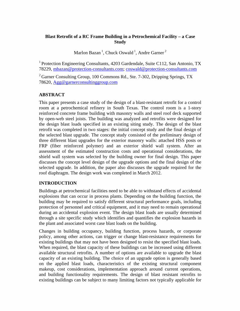
The second option for the wall upgrade consisted of installing FRP (fiber-reinforced polymer) strips or mats bonded to the interior (non-blast loaded) and exterior (blast loaded) face of the masonry walls. The FRP strips would act as tension reinforcement composite with the wall, to provide flexural strength to interior CMU wall wythe during inbound response and the exterior brick wythe during rebound. In order to provide the required strength to the walls, this upgrade required 50% to 100% coverage of the wall area with CFRP (Carbon FRP) material. Lateral support at bottom of the walls is provided using a steel angle anchored to the floor slab with mechanical anchors and thru bolts attaching the bottom of the wall to the angle. Lateral support at the top of the walls is provided by an HSS 10x2 tube installed just below the perimeter beam and spanning between the RC perimeter columns. The HSS tube is connected to the columns using steel angles and mechanical anchors and using thru bolts along the length of the tube to attach the top of the wall to the tube. Figure 3 shows a schematic representation of a typical HSS posts at its connections. The upgraded wall is not directly attached to the bottom of the concrete perimeter beam since this would cause too much torsion. Also, the interior masonry wall and the outer veneer wall on the West wall must be upgraded to act compositely as a solid wall to resist a higher design blast load. An arrangement of masonry screw anchors (¾” screws anchors at 6-in o.c. e.w.) was designed to transfer the in-place shear and thereby provide composite action between the wythes for this wall.
5
Figure 3. Exterior wall upgrade – Option 2: FRP
Option 3: Shield Wall
The third upgrade option consists of an attached shield wall around the perimeter of the building. The shield wall resists the applied blast load and protects the existing masonry walls from the blast overpressure. The shield wall consists of a corrugated steel panel supported by heavy steel beams (W14x38), spaced at 4 feet on center, that span horizontally between the reinforced concrete columns around the perimeter of the building. The columns protrude out from the building by a sufficient distance so that the shield wall can deflect under blast load without deflecting into the existing masonry wall. The controlling factor for the design of the new beams and panel was that their deflection under blast load would not cause a buildup of pressure in the gap between the new wall and existing wall that exceeded the lateral pressure design load for the existing walls. The steel beams are connected to the columns by mechanical anchors, as shown in Figure 4.
The concrete columns were analyzed as spanning between the foundation and the roof deck and loaded by the shield wall beams at third points. The analysis showed that the columns resisted the blast loads with acceptable damage, except the columns at the West elevation (higher blast load) which require strengthening.
Lateral Force Resisting System
The upgrade of the diaphragm consists in adding screw connections at the deck supports (between the existing deck and the top chord of the joists) and at the deck sidelaps in order to obtain the required in-plane shear strength capacity. This is required for all upgrade options. In addition, for upgrades options 1 (HSS posts) and 2 (FRP), which transmitted higher lateral loads into the diaphragm, the connection of the diaphragm to the concrete perimeter beam also required an upgrade by adding anchor bolts from the ledge angle (supporting the deck) into the concrete perimeter beam along the East and West walls.

6
Figure 4. Exterior wall upgrade – Option 3: Shield Wall
The perimeter reinforced concrete moment frames were analyzed dynamically as SDOF systems, considering the blast load over the tributary area of wall laterally supported by the concrete frames. The reinforced concrete frames of the building consist of columns spaced at approximately 16-ft on center and a 3’-8” deep concrete girder. This girder is assumed to develop the full moment capacity of the columns in a sway response mode so that the frames can act as moment resisting frames. The frames were analyzed as equivalent SDOF systems with sway response, where the stiffness and resistance of the SDOF system was provided by the columns responding with a fixed connection at the top to the girder and a pinned connection at the base. The blast load for the analysis of each frame was calculated as the design blast load applied over the tributary area of the frame. The mass of the roof and 1/3 of the walls was included in the equivalent SDOF system. The maximum dynamic deflection from the SDOF analyses of the concrete frames was used to determine support rotation for the concrete columns due to frame sway response, which was adequate for the required Medium Response level.
Comparison of Upgrade Options
Usually, the important aspects to consider for the selection of upgrades are the cost, the disruption to operations during and after construction, and the required construction time. Garner Consulting Group (GCG) developed cost estimates based on the concept level design by PEC for each of the wall upgrade options. The estimated upgrade cost for the building upgrade with the shield wall concept was in the range of $1M, including costs for final design, construction, and a contingency. The costs for the other upgrade options were considerably higher (i.e. more than 25% higher). The cost for the shield wall concept was reduced significantly for this
1C metal panel
W14x38 beams @ 4ft o.c. (typ.)
Self-drillingscrews
Expansionanchors

7
building by the fact the existing frame could be used to support the wall. In many cases, a shield wall would require new framing at a standoff of approximately one foot from the existing wall, which would increase the cost. It is important to emphasize that upgrade costs can be highly affected by numerous building-specific factors.
Another aspect that was considered when selecting the wall upgrade was the potential disruptions of the building operations during construction. Upgrade options 1 and 2 (HSS posts and FRP) require access to the interior side of walls, which imposes construction challenges (e.g. removal of interior finishing and equipment, limited work space) and limits the building operations during construction. In general, the HSS posts can be installed on the exterior side of solid walls; however, it is difficult to support the interior wall with posts in this case and the post connection at the top to the concrete frame would be problematic. On the other hand, the majority of the construction for upgrade option 3 (shield wall) would be conducted on the exterior of the building, reducing the interference with building operations and utilities and appurtenances at the interior of the building. Buildings in petrochemical facilities typically have utility fixtures on the exterior face of walls and may have restricted access due to pipelines or equipment around the building. However, in this particular case, the access from the exterior was unrestricted and, therefore, it would be easier to do most of the construction work from the outside of the building.
PHASE II: FINAL UPGRADE DESIGN
After reviewing the upgrade design concepts and cost estimates by PEC and GCG, the building owner selected the shield wall upgrade (Option 3) for final design. The shield wall components were designed using the SDOF methodology and response criteria for Medium Response, as specified in Design of Blast-Resistant Buildings in Petrochemical Facilities (ASCE, 2010). Furthermore, in order to limit the gap pressure in the space between the shield wall and the existing masonry wall, the shield wall panel and purlins were designed to remain elastic and limit their dynamic deflections to relatively small values, well below the response limits for Medium Response. The final design of the shield wall upgrade is described in this section.
Typical Shield Wall Components
The cladding of the shield wall consists of 3-in deep, gage 22 (0.0295-in thick), corrugated metal panel spanning vertically and supported by steel purlins. The steel purlins consist of W14x38 structural steel members (Grade 50), spaced at 3.75 and 4 feet on center spanning between the reinforced concrete columns around the perimeter of the building. Figure 5 shows a typical cross-section of the shield wall. The steel purlins are welded to a ½-in steel base plate and connected to the perimeter columns using ¾-in diameter expansion (wedge) anchors. The expansion anchors provide support for the purlins during rebound. These anchors were designed for a tension design load based on the maximum elastic rebound response of the purlin, including a safety factor of 2 applied to the maximum equivalent static tension load. A closure panel is provided at the top of the new shield wall to prevent pressure from leaking into the gap between the new wall and existing wall, as shown in Figure 6.

8
Figure 5. Typical shield wall cross-section

9
Figure 6. Typical closure plate
Shield Wall with Blast-Resistant Doors
The shield wall includes framing for blast-resistant doors at locations of existing doors where building entrance is still required. At other door locations, where an entrance is no longer required, the door opening in the existing wall is blocked with CMU. The framing for the blast-resistant doors at the shield wall consists of an HSS 14x6 header spanning between columns, in lieu of the second purlin from top of the shield wall, and HHS jambs spanning between the floor slab and the header. The HSS header and jamb members facilitate the attachment of the blast-resistant doors, which can be attached to the sides of the HSS members. A concrete slab was designed to provide lateral support at the bottom of the HSS door jambs. The slab is attached to the side of the existing grade beam using #4 bars anchored with epoxy adhesive to the side of the grade beams. The HSS jambs are welded to steel plates embedded into the extended concrete slab with headed stud anchors. Figure 7 shows a typical slab extension.
Figure 7. Typical concrete slab extension

10
Strengthening of West Columns
The SDOF analysis of the concrete columns at the interior bays (non-corner corner columns) at West wall, where the design blast load was highest, showed that these columns would require to be strengthened in order to laterally support the shield wall while satisfying the response limits for Medium Response. Steel posts were designed to strengthen these columns. The HSS 8x2 posts were bolted to each side of the columns so that they would laterally deflect with the columns as a “stacked system”, where the post and column deflect together but are not designed to act compositely. This stacked system was also designed using the SDOF approach, where the resistance functions for the steel post and reinforced concrete column were added together as the total resistance of the stacked system. The connection of the posts to the columns consisted of ¾-in (diameter) expansion anchors spaced at 12-in on center along the length of the column. Figure 8 shows a typical column upgrade.
Figure 8. Typical upgrade to perimeter columns at West wall
Gap Pressure
The calculated deflection histories of the panel and beams of the shield wall were used to calculate the volume change in the gap between the shield wall and the existing masonry wall and the corresponding pressure change assuming an adiabatic compression of air in the gap. A time stepping method, which allows air mass flow through required small openings in the existing wall into the volume of the building, was used to calculate the buildup pressure in the gap. The stiffness of the shield wall system and area of small openings in the existing wall were designed to keep the peak pressure in the gap to a maximum of 20 psf. This pressure is a typical wind design pressure for building walls. Analysis showed that vent openings were only required at the West wall in order to keep the buildup pressure below 20 psf. These openings can be covered with a lightweight material, weighting 2 psf or less (e.g. sheet metal panel), that is lightly adhered on the inner face of the CMU wall so that very little pressure is required to blow out the cover on the opening. Also, the openings were positioned above the interior ceiling level to minimize the effects of any sudden air

11
flow on building occupants. In addition, all existing exterior windows around the buildings are removed and replaced with CMU block. Existing doors are replaced with blast doors or filled in with CMU block as part of the upgrade. The existing masonry wall must be able to resist a 20 psf pressure load and must be inspected to ensure it is in good condition and repaired as necessary. Also, as a typical precaution for blast-loaded buildings, and because there will be some pressure venting into the building, all heavy items on the interior of the building that are supported by the roof, and could fall and injure building occupants, should be well attached to the roof structural members in a similar manner as in buildings subject to earthquake loads.
Roof Diaphragm Upgrade
The existing roof deck consists of a 22-gage corrugated steel non-composite (form) deck with insulating concrete infill. The deck is connected to the top chord of the roof joists with ½-in puddle welds at 15-in o.c. (30/3 pattern) and does not have sidelap connections. The in-plane shear capacity of the existing roof diaphragm was lower than the in-plane shear demand for blast load in the North-South direction and it needed to be increased in order to be able to transfer the reaction loads from the shield wall into the moment frames. The roof diaphragm upgrade consists of adding ¼-in self-drilling screws at 15-in on center between the deck and top chord of joists, and adding four No. 12 self-drilling screws at sidelaps within each span between joists. This upgrade is only needed for diaphragm action from load in the North-South direction and it can be reduced over the middle area of the roof considering the linear variation of the in-plane shear demand. The existing diaphragm strength for blast load in the East-West direction was adequate.
At the North and South sides, the roof joists are welded to steel angles with embedded anchors into the concrete perimeter frame beam. At the East and West sides, the roof diaphragm is connected to the East and West moment frames through the roof deck which is supported by a ledge angle that is anchored at interior side of the perimeter beam. The existing connection of the ledge angle into the perimeter beam consists of ½” anchor bolts at 4-ft on center. The capacity of this connection is adequate for the in-plane shear (diaphragm) forces due to blast load in the North-South direction. However, the existing connection of the roof deck to the ledge angle needs to be strengthened. The upgrade of this connection consists in adding self-drilling screws at 5-in on center (at every other flute) from the existing ledge angle into the roof deck along the East and West walls. Since the roof deck is covered by insulting concrete fill, all screws included in the roof upgrade are to be installed from the inside of the building, from the steel supports into the metal deck.
Other Design Considerations
It was recommended that all structural steel (purlins and door framing members) of the shield wall shall be hot-dip galvanized (zinc coated) in order to provide resistant to corrosion. In addition, base plates and concrete expansion anchors used to connect the structural steel members of the shield wall must also be hot-dip galvanized. Welding of all hot-dip galvanized steel members shall be in accordance with AWS (American Welding Society) specifications for welding of zinc-coated steel,

12
including coating of completed welds with liquid organic zinc compound per ASTM A780 specifications. In addition, self-drilling screws used for the connections of sheet metal in the shield wall shall be coated with an organic polymer coating (e.g. Kwik-Cote, Climaseal®), which insulate the screw material from the base metal, and shall use weatherproof EPDM bonded sealing washers.
SUMMARY AND CONCLUSIONS
This paper presents the design of a blast-resistant retrofit for an existing building at a petrochemical refinery. The design process included a preliminary design phase where three different upgrade concepts and corresponding cost estimates were developed. After consideration of the design concepts and estimated costs, a shield wall upgrade was selected by the building owner. The final design of the shield wall components and connections were discussed. At the time of completion of this paper, the authors do not have final information about the decision by the building owner to implement the selected upgrade final design. Other options, such as replacing the control room with a BRM (blast-resistant modular) building, are being considered by the building owner.
REFERENCES
ASCE Task Committee on Blast-Resistant Design, Design of Blast-Resistant Buildings in Petrochemical Facilities, 2nd ed., American Society of Civil Engineers, Reston, VA, 2010.
SBEDS (Single degree of freedom Blast Effects Design Spreadsheet), Version 4.1, US Army Corps of Engineers Omaha District, Protective Design Center, Omaha, Nebraska, August, 2008.
UFC 3-340-02, "Structures to Resist the Effects of Accidental Explosions," U.S. Department of Defense, Washington, DC, November 1990.