
BladeCenter: Serial over LAN Setup...
64
BladeCenter Serial over LAN Setup Guide
Transcript of BladeCenter: Serial over LAN Setup...

BladeCenter
Serial over LAN Setup Guide
���

BladeCenter
Serial over LAN Setup Guide
���

Note: Before using this information and the product it supports, read the general information in Appendix A, “Getting helpand technical assistance,” on page 51 and Appendix B, “Notices,” on page 53.
Twelfth Edition (November 2009)
© Copyright IBM Corporation 2009.US Government Users Restricted Rights – Use, duplication or disclosure restricted by GSA ADP Schedule Contractwith IBM Corp.
Contents
Chapter 1. Introduction . . . . . . . . 1Hardware and firmware requirements . . . . . . 2
Hardware requirements. . . . . . . . . . 2Firmware requirements . . . . . . . . . . 3Checking firmware versions . . . . . . . . 4
Starting the BladeCenter management-module Webinterface . . . . . . . . . . . . . . . . 5
Chapter 2. General configuration . . . . 7Configuring the global SOL settings for theBladeCenter unit . . . . . . . . . . . . . 7Configuring the management module . . . . . . 9Installing and configuring SSH for SOL . . . . . 11Enabling SOL for blade servers . . . . . . . . 12Updating and configuring the blade server BIOS . . 13
Chapter 3. Operating systemconfiguration . . . . . . . . . . . . 15Linux configuration . . . . . . . . . . . 15
Red Hat Enterprise Linux ES 2.1 configuration . 15SUSE SLES 8.0 configuration . . . . . . . 19Installing the Ethernet controller device driver forLinux operating systems . . . . . . . . . 21
Microsoft Windows 2003 Standard Editionconfiguration . . . . . . . . . . . . . . 22
Chapter 4. Special componentrequirements . . . . . . . . . . . . 25Configuring the BladeCenter HS22 Type 7870 bladeserver . . . . . . . . . . . . . . . . 25Configuring the BladeCenter HS20 Type 8832 andHS20 Type 8843 blade servers . . . . . . . . 27
HS20 Type 8832 SOL jumper placement . . . . 28Updating the integrated systems managementprocessor firmware . . . . . . . . . . . 28Updating the Broadcom Ethernet controllerfirmware . . . . . . . . . . . . . . 29
Configuring the BladeCenter HS40 Type 8839 bladeserver . . . . . . . . . . . . . . . . 29
Updating the Baseboard Management Controllerfirmware . . . . . . . . . . . . . . 29Updating and configuring the BIOS . . . . . 30
Configuring the BladeCenter JS20 Type 8842 bladeserver . . . . . . . . . . . . . . . . 30
Updating the open firmware (BIOS) . . . . . 31Updating the integrated systems managementprocessor firmware . . . . . . . . . . . 31Updating the Broadcom Ethernet controllerfirmware . . . . . . . . . . . . . . 32
Configuring the IBM 4-Port Gb Ethernet SwitchModule for BladeCenter . . . . . . . . . . 32Configuring the Nortel Networks Layer 2-7 GbESwitch Module for IBM BladeCenter . . . . . . 33Configuring the Cisco Systems Intelligent GigabitEthernet Switch Module for the IBM BladeCenter . 34Connecting an Intelligent Copper Pass-thru Module 35
Chapter 5. Using SOL . . . . . . . . 37Starting an SOL session . . . . . . . . . . 37
Starting a command-line Telnet connection . . . 38Establishing a serial connection . . . . . . . 38Starting a command-line Secure Shell (SSH)connection. . . . . . . . . . . . . . 39Starting an SOL session from the command-lineinterface . . . . . . . . . . . . . . 39
Ending an SOL session . . . . . . . . . . 40Monitoring SOL session status . . . . . . . . 40Restarting a blade server through SOL . . . . . 43Mounting and unmounting media for Linuxoperating systems . . . . . . . . . . . . 44
Chapter 6. Troubleshooting SOL. . . . 45Management module indicates that blade serverdoes not support SOL . . . . . . . . . . . 45Blade server shows SOL status of Not Ready . . . 46SOL session opens and drops . . . . . . . . 47Trouble entering SOL commands or receivingdouble prompts . . . . . . . . . . . . . 48Garbage characters in an SOL session. . . . . . 48
Appendix A. Getting help and technicalassistance . . . . . . . . . . . . . 51Before you call . . . . . . . . . . . . . 51Using the documentation . . . . . . . . . . 51Getting help and information from the World WideWeb . . . . . . . . . . . . . . . . . 52Software service and support . . . . . . . . 52Hardware service and support . . . . . . . . 52IBM Taiwan product service . . . . . . . . . 52
Appendix B. Notices . . . . . . . . . 53Trademarks . . . . . . . . . . . . . . 53Important notes . . . . . . . . . . . . . 53
Index . . . . . . . . . . . . . . . 55
© Copyright IBM Corp. 2009 iii

iv BladeCenter: Serial over LAN Setup Guide

Chapter 1. Introduction
Serial over LAN (SOL) provides a means to manage servers remotely by using acommand-line interface (CLI) over a Telnet or Secure Shell (SSH) connection. SOLis required to manage servers that do not have keyboard/video/mouse (KVM)support, such as the JS20 Type 8842 blade server.
SOL provides console redirection for both BIOS and the blade server operatingsystem. The SOL feature redirects server serial-connection data over a LANwithout the need for special cabling. The SOL connection enables blade servers tobe managed from any remote location with network access. The advantages of SOLinclude:v Remote administration without keyboard, video, or mouse (headless servers)v Reduced cabling and no need for a serial concentratorv Standard Telnet interface that eliminates the need for special client software
The IBM® BladeCenter management module command-line interfaces provideaccess to the text-console command prompt on each blade server through a SOLconnection, enabling the blade servers to be managed from a remote location. Thisdocument explains how to update and configure BladeCenter components for SOLoperation using the BladeCenter management-module Web interface. You can alsoperform many configuration procedures using the management-modulecommand-line interface or the simple network management protocol (SNMP). Seethe BladeCenter Management Module Command-Line Interface Reference Guide forinformation about the management-module command-line interface andinstructions about how to use it. All BladeCenter unit types, including theBladeCenter T unit, are referred to throughout this document as the BladeCenterunit. Unless stated otherwise, all descriptions and instructions in this documentapply to all BladeCenter unit configurations.
In the BladeCenter environment, the integrated system management processor(ISMP) and network interface controller (NIC) on each blade server routes theserial data from the blade server serial communications port to the networkinfrastructure of the BladeCenter unit, including an Ethernet-compatible I/Omodule that supports SOL communication. BladeCenter components areconfigured for SOL operation through the BladeCenter management module. Themanagement module also acts as a proxy in the network infrastructure to couple aclient running a Telnet session with the management module to an SOL sessionrunning on a blade server, enabling the Telnet client to interact with the serial portof the blade server over the network. Because all SOL traffic is controlled by androuted through the management module, administrators can segregate themanagement traffic for the BladeCenter unit from the data traffic of the bladeservers.
To start an SOL connection with a blade server, you must first start a Telnetcommand-line interface session with the management module. When this Telnetcommand-line interface session is running, you can start a remote-console SOLsession with any blade server in the BladeCenter unit that is set up and enabledfor SOL operation. You can establish up to 20 separate Web interface, Telnet, serial(advanced management module only), or SSH sessions with a BladeCentermanagement module. For a BladeCenter unit, this enables you to have 14simultaneous SOL sessions active (one for each of up to 14 blade servers) with 6additional command-line interface sessions available for BladeCenter unit
© Copyright IBM Corp. 2009 1

management. For a BladeCenter T unit, this enables you to have 8 simultaneousSOL sessions active (one for each of up to 8 blade servers) with 12 additionalcommand-line interface sessions available for BladeCenter unit management. Ifsecurity is a concern, you can use Secure Shell (SSH) sessions, or connections madethrough the serial management port that is available on the advanced managementmodule, to establish secure Telnet command-line interface sessions with theBladeCenter management module before starting an SOL console redirect sessionwith a blade server.
The most recent versions of all BladeCenter documentation is available athttp://www.ibm.com/support/.
Hardware and firmware requirementsThe BladeCenter unit must be correctly configured before you can use thecommand-line interface and SOL. This section describes the hardware and softwarethat are required for the command-line interface and SOL.
Hardware requirementsAll BladeCenter components, except for the BladeCenter HS20 Type 8678 bladeserver, are SOL capable. All blade servers must be configured to enable SOLoperation. Some of the older BladeCenter components require additionalconfiguration to support SOL operation.
To use the SOL feature, the following hardware is required:v An SOL-capable blade server.
The BladeCenter HS20 Type 8678 blade server does not support SOL operation.You can use the console command to control a blade server through SOL onlyon blade server types that support SOL functionality that have the requiredfirmware levels (see Table 1 on page 3).
v An Ethernet I/O module installed in I/O-module bay 1. For systems usingmanagement channel auto discovery (MCAD), SOL can use I/O modulesinstalled in other I/O-module bays (see the BladeCenter Advanced ManagementModule User's Guide for additional information about MCAD).
The following blade servers have specific requirements for SOL operation:v For the BladeCenter HS20 Type 8832 and Type 8843 blade servers, and LS20
Type 8850 blade server:– SOL uses the first network interface, Ethernet 1 (eth1 or Planar Ethernet 1), of
the blade server to communicate. When this network interface attempts toboot through PXE or DHCP, the network interface is reset, causing the currentSOL session to be dropped and have a new status of Not Ready. If yourequire booting through PXE or DHCP, use the second network interface,Ethernet 2 (eth2 or Planar Ethernet 2), of the blade server and install anEthernet I/O module in I/O-module bay 1.
– For the BladeCenter HS20 Type 8832 blade server, jumper J28 must beinstalled in the correct position. See “HS20 Type 8832 SOL jumper placement”on page 28 for information.
v For the BladeCenter JS20 Type 8842 blade server, SOL uses the first networkinterface, Ethernet 1 (eth1 or Planar Ethernet 1), of the blade server tocommunicate. When this network interface attempts to use BOOTP, the networkinterface is reset, causing the current SOL session to be dropped and have a new
2 BladeCenter: Serial over LAN Setup Guide

status of Not Ready. If you require BOOTP, use the second network interface,Ethernet 2 (eth2 or Planar Ethernet 2), of the blade server and install an EthernetI/O module in I/O-module bay 1.
Firmware requirementsMake sure that you are using the latest versions of device drivers, firmware, andBIOS for your blade server, management module, and other BladeCentercomponents. Go to http://www.ibm.com/support/ for the latest informationabout upgrading the device drivers, firmware, and BIOS for BladeCentercomponents. The latest instructions are in the documentation that comes with theupdates.
The firmware level of most BladeCenter components supports SOL operation.Some of the older BladeCenter components must have their firmware upgraded tosupport SOL operation. The following table lists the firmware levels that arerequired for older BladeCenter components to support SOL operation. If acomponent is not listed in the table, all firmware levels for that component supportSOL operation.
Table 1. Firmware levels required for SOL for older BladeCenter components
Component Firmware level
BladeCenter Management Module 1.08 or later
BladeCenter HS20 Type 8678 blade server No SOL support
Bla
deC
ente
rH
S20
Type
8832
blad
ese
rver BladeCenter HS20 Type 8832 blade server BIOS 1.03 or later
BladeCenter HS20 Type 8832 blade server diagnostics 1.02 or later
BladeCenter HS20 Type 8832 blade server ISMP 1.03 or later
BladeCenter HS20 Type 8832 blade server Broadcom Ethernet ControllerBoot ROM
3.21 or later
BladeCenter HS20 Type 8832 blade server Broadcom Ethernet ControllerFirmware
2.2 or later
BladeCenter HS20 Type 8832 blade server Broadcom Ethernet ControllerDiagnostic Utility
1.06 or later
BladeCenter HS20 Type 8832 blade server Broadcom Ethernet ControllerLinux Device Driver
7.1.22 or later
IBM 4-Port Gb Ethernet Switch Module for BladeCenter 1.04 or later
Nortel Networks Layer 2-7 GbE Switch Module for IBM BladeCenter (4-port switch) See the IBM SupportWeb site 1
Note 1: Go to http://www.ibm.com/support/ for the latest information about firmware levels that support SOL.
Chapter 1. Introduction 3
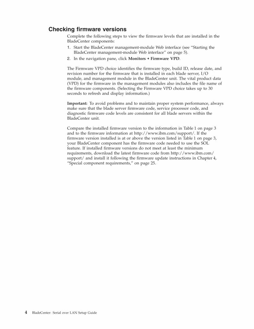
Checking firmware versionsComplete the following steps to view the firmware levels that are installed in theBladeCenter components:1. Start the BladeCenter management-module Web interface (see “Starting the
BladeCenter management-module Web interface” on page 5).2. In the navigation pane, click Monitors → Firmware VPD.
The Firmware VPD choice identifies the firmware type, build ID, release date, andrevision number for the firmware that is installed in each blade server, I/Omodule, and management module in the BladeCenter unit. The vital product data(VPD) for the firmware in the management modules also includes the file name ofthe firmware components. (Selecting the Firmware VPD choice takes up to 30seconds to refresh and display information.)
Important: To avoid problems and to maintain proper system performance, alwaysmake sure that the blade server firmware code, service processor code, anddiagnostic firmware code levels are consistent for all blade servers within theBladeCenter unit.
Compare the installed firmware version to the information in Table 1 on page 3and to the firmware information at http://www.ibm.com/support/. If thefirmware version installed is at or above the version listed in Table 1 on page 3,your BladeCenter component has the firmware code needed to use the SOLfeature. If installed firmware versions do not meet at least the minimumrequirements, download the latest firmware code from http://www.ibm.com/support/ and install it following the firmware update instructions in Chapter 4,“Special component requirements,” on page 25.
4 BladeCenter: Serial over LAN Setup Guide
Starting the BladeCenter management-module Web interface
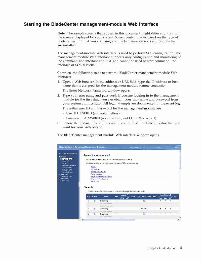
Note: The sample screens that appear in this document might differ slightly fromthe screens displayed by your system. Screen content varies based on the type ofBladeCenter unit that you are using and the firmware versions and options thatare installed.
The management-module Web interface is used to perform SOL configuration. Themanagement-module Web interface supports only configuration and monitoring ofthe command-line interface and SOL and cannot be used to start command-lineinterface or SOL sessions.
Complete the following steps to start the BladeCenter management-module Webinterface:1. Open a Web browser. In the address or URL field, type the IP address or host
name that is assigned for the management-module remote connection.The Enter Network Password window opens.
2. Type your user name and password. If you are logging in to the managementmodule for the first time, you can obtain your user name and password fromyour system administrator. All login attempts are documented in the event log.The initial user ID and password for the management module are:v User ID: USERID (all capital letters)v Password: PASSW0RD (note the zero, not O, in PASSW0RD)
3. Follow the instructions on the screen. Be sure to set the timeout value that youwant for your Web session.
The BladeCenter management-module Web interface window opens.
Chapter 1. Introduction 5

6 BladeCenter: Serial over LAN Setup Guide
Chapter 2. General configuration
Note: The sample screens that appear in this document might differ slightly fromthe screens displayed by your system. Screen content varies based on the type ofBladeCenter unit that you are using and the firmware versions and options thatare installed.
This section provides instructions for configuring the BladeCenter unit to operateusing SOL. You must perform the following procedures:v Make sure that all BladeCenter components and firmware meet the minimum
SOL requirements (see “Hardware and firmware requirements” on page 2).v Configure the BladeCenter unit for SOL operation (see “Configuring the global
SOL settings for the BladeCenter unit”).v Configure the management module for SOL operation (see “Configuring the
management module” on page 9).v If required, configure BladeCenter components for SOL operation (see Chapter 4,
“Special component requirements,” on page 25).v Update and configure BladeCenter BIOS for SOL operation (see “Updating and
configuring the blade server BIOS” on page 13).v Configure the operating system that is installed on each blade server to enable
SOL (see Chapter 3, “Operating system configuration,” on page 15).v If secure SOL sessions over a network are required, install and configure SSH for
SOL (see “Installing and configuring SSH for SOL” on page 11).v Enable the blade servers for SOL operation (see “Enabling SOL for blade
servers” on page 12).
Perform the SOL configuration that is shared by all BladeCenter components usingthe management-module Web interface. The management-module Web interfacesupports only configuration and monitoring of the command-line interface andSOL and cannot be used to start command-line interface or SOL sessions.
You can also perform some SOL configuration using the management-modulecommand-line interface or the Simple Network Management Protocol (SNMP). Seethe BladeCenter Management Module Command-Line Interface Reference Guide forinformation about the management-module command-line interface andinstructions for using it.
Configuring the global SOL settings for the BladeCenter unitComplete the following steps to configure the global SOL settings for theBladeCenter unit:1. Start the BladeCenter management-module Web interface (see “Starting the
BladeCenter management-module Web interface” on page 5).2. In the navigation pane, click Blade Tasks → Serial Over LAN. In the
management-module information page that opens make sure that the settingsmatch the following default values or are set to the values that are required byyour network configuration. Unless otherwise noted, the defaultmanagement-module SOL settings provide the best overall SOL performance.(For advanced management modules, click the Serial Over LAN configurationlink to access the SOL settings.)
© Copyright IBM Corp. 2009 7

The following illustration shows SOL settings for management modules other thanan advanced management module.
The following illustration shows SOL settings for an advanced managementmodule.
Note: For the advanced management module, the SOL VLAN ID and the BSMPIP address range are set on the Blade Tasks → Configuration page (see theAdvanced Management Module User's Guide for information).
The SOL settings and recommended values are:v Serial Over Lan: Enabled
Use this field to enable or disable SOL globally for the BladeCenter unit. If SOLis enabled globally and if SOL is enabled for a blade server, an SOL session canbe established with that blade server. If SOL is disabled globally, no SOLsessions can be established with any blade servers in the BladeCenter unit.
v SOL VLAN ID (management modules other than the advanced managementmodule)
8 BladeCenter: Serial over LAN Setup Guide

– For all switch modules other than the Cisco Systems Intelligent GigabitEthernet Switch Module for the IBM BladeCenter, the SOL VLAN ID must beset to 4095 (default value).
– For the Cisco Systems Intelligent Gigabit Ethernet Switch Module for the IBMBladeCenter the SOL VLAN ID is set as follows:- For Cisco IOS releases earlier than 12.1(22)EA6a, the SOL VLAN ID can be
set to any value between 3 and 1001: it cannot be set to the default value of4095.
- For Cisco IOS release 12.1(22)EA6a and later, the SOL VLAN ID is set to adefault value of 4095. If desired, you can still set your own defined VLANID.
Note: If your blade server has a Broadcom Ethernet controller and youwant to use an SOL VLAN ID of 4095 for the Cisco Systems IntelligentGigabit Ethernet Switch Module, upgrade to the latest versions of bladeserver Broadcom Ethernet Controller firmware (minimum level supportedis 1.20.14).
If you set the SOL VLAN ID to a custom value, write it down for later useduring the configuration process.
v BSMP IP Address Range: x.x.x.x (management modules other than theadvanced management module)This is a mandatory field where x.x.x.x is the base IP address for blade serversthat is used for internal communication inside the BladeCenter unit. The IPaddress that SOL uses to communicate with the blade system managementprocessor (BSMP) of each blade server is based on the IP address that is set inthis field. For example, if the value that you enter is 10.1.1.1, the blade server inblade bay 1 will have IP address 10.1.1.1, the blade server in blade bay 2 willhave IP address 10.1.1.2, and so on.
v Accumulate timeout: 25 (default value is 5 for management modules other thanthe advanced management module and 150 for the advanced managementmodule)
v Send threshold: 250
v Retry count: 3
v Retry interval: 2500 (default value is 250)
Do not attempt to enable or disable SOL on any of the blade servers that are listedin the Serial Over LAN Status section.
Configuring the management moduleBefore you configure the management module for SOL operation, review thefollowing information:v Make sure that the management-module external network interface (eth0)
configuration is valid for your production network. This configuration can beobtained from a DHCP server or set statically.
v For management module types other than the advanced management module,the management-module internal network interface (eth1) and the Ethernet I/Omodule configuration can be different from that of the management-moduleexternal network interface (eth0); however, the management-module internalnetwork interface (eth1) and the Ethernet I/O module configuration must be inthe same subnet. The management-module internal interface (eth1) is exposed tothe external network through the management module, so it must not conflictwith any other addresses on your production network. If you use a
Chapter 2. General configuration 9

configuration for the Ethernet I/O module that is not valid for your productionnetwork, you will not be able to update the firmware or manage your EthernetI/O module through a Web interface.
v Telnet sessions with the BladeCenter management module do not have a timeoutvalue set by default. If no timeout value is set, Telnet sessions will remain activeindefinitely. See the BladeCenter Management Module Command-Line InterfaceReference Guide for information about configuring the Telnet session timeoutvalue for the management module.
v The SOL blade system management processor (BSMP) address range can includeany valid IP addresses that do not conflict with any of the IP addresses of theblade servers. The BSMP address range is used for internal communicationbetween the blade server and the I/O module and is not exposed to the externalnetwork.
Complete the following steps to update the management-module firmware andconfigure the management module to enable SOL:1. Start the BladeCenter management-module Web interface (see “Starting the
BladeCenter management-module Web interface” on page 5).2. Complete the following steps to update the BladeCenter management module
firmware:a. Download the latest management-module firmware from
http://www.ibm.com/support/.b. Update the management-module firmware, following the instructions that
come with the update file that you downloaded.3. Start the BladeCenter management-module Web interface (see “Starting the
BladeCenter management-module Web interface” on page 5).4. Complete the following steps to enable SOL for the management module:
a. For management module types other than the advanced managementmodule, complete the following steps to configure the internal networkinterface (eth1) settings:1) In the navigation pane, click MM Control → Network Interfaces.2) Scroll to the Internal Ethernet Interface (eth1) section.3) Make sure that Interface is set to Enabled.4) Set the Static IP Configuration fields to the values that are required for
your physical network. The values must be in the following formats:v IP address: x.x.x.x
v Subnet mask: x.x.x.x
v Gateway address: x.x.x.x
The static IP configuration values specify valid IP addresses of the formx.x.x.x, where each x is a number from 0 to 255.
5) Click Save; then, click OK or Yes to confirm. Do not restart themanagement module.
b. Complete the following steps to configure the Ethernet I/O modulenetwork settings:
Note: If you are using management channel auto discovery (MCAD),replace references to I/O-module bay 1 in the following procedure with theI/O module bay number that is actually being used (see the BladeCenterAdvanced Management Module User's Guide for additional information aboutMCAD).1) In the navigation pane, click I/O Module Tasks → Configuration.
10 BladeCenter: Serial over LAN Setup Guide

2) Scroll to the Bay 1 (Ethernet SM)* section.3) Set the values in the New Static IP Configuration fields, if they are not
already correct as listed in the Current IP Configuration section. Thevalues must be in the following formats:v IP address: x.x.x.x
v Subnet mask: x.x.x.x
v Gateway address: x.x.x.x
The static IP configuration values specify valid IP addresses of the formx.x.x.x, where each x is a number from 0 to 255.
4) If you changed any values, click Save.5. Complete the following steps to restart the management module. Restarting the
management module ends the current BladeCenter management-module Webinterface session.a. In the navigation pane, click MM Control → Restart MM.b. Click Restart.c. Click OK to confirm.d. Click Yes to restart the management module and end the session.
Installing and configuring SSH for SOLComplete the following steps to install and configure Secure Shell Server (SSH) forSOL:1. Start the BladeCenter management-module Web interface (see “Starting the
BladeCenter management-module Web interface” on page 5).2. If you have not previously installed a security key file, complete the following
steps. Otherwise, go to step 3.a. In the navigation pane, click MM Control → Security.b. Download the latest version of the SSH security key file from
http://www.ibm.com/support/. Navigate to the Install SSL/SSH sectionand click BladeCenter firmware update.
c. Click Browse and select the file that was downloaded in step 2b.d. Click Install SSL/SSH.e. Scroll to the Install SSL/SSH section and click Configure and enable.
3. Complete the following steps to generate the SSH Server Private Key:a. In the navigation pane, click MM Control → Security.b. Scroll to the SSH Server Key Management section and click Generate SSH
Server Private Key.c. Click OK to confirm.
4. Complete the following steps to enable SSH:a. Scroll to the Secure Shell (SSH) Server section.b. Select Enabled for the SSH Server option; then, click Save.c. Click OK to confirm.
5. Complete the following steps to restart the management module. Restarting themanagement module ends the current BladeCenter management-module Webinterface session.a. In the navigation pane, click MM Control → Restart MM.b. Click Restart.c. Click OK to confirm.
Chapter 2. General configuration 11

d. Click Yes to restart the management module and end the session.
You can now use an SSH client to start a secure Telnet session with themanagement module and secure SOL sessions with the blade servers.
Enabling SOL for blade serversSOL must be enabled both globally for the BladeCenter unit (see “Configuring theglobal SOL settings for the BladeCenter unit” on page 7) and individually for eachblade server where you plan to start an SOL session.
Note: Make sure that console redirection is enabled for your blade server, withport 2 (COM 2) specified as the remote console port. Remote console configurationinformation for the HS20 Type 8832, HS20 Type 8843, and HS40 Type 8839 bladeservers is in Chapter 4, “Special component requirements,” on page 25. See theInstallation and User's Guide for your blade server for information about configuringblade server BIOS settings such as console redirection.
Complete the following steps to enable SOL for a blade server:1. Start the BladeCenter management-module Web interface (see “Starting the
BladeCenter management-module Web interface” on page 5).2. Complete the following steps to enable SOL on the blade servers:
a. In the navigation pane, click Blade Tasks → Serial Over LAN; then, scroll tothe Serial Over LAN Status section.
b. Select each blade server that will have SOL enabled; then, click or selectEnable Serial Over LAN. (For advanced management modules, you willalso need to click Perform Action.) Selecting the check box at the top of thestatus table selects all blade servers. The SOL column of the table will showa status of Enabled for each of the blade servers that was selected. The SOLSession column of the table indicates a status of Not Ready for each of theblade servers that was selected.
c. To disable SOL for a blade server, select each blade server that will haveSOL disabled; then, click or select Disable Serial Over LAN. (For advancedmanagement modules, you will also need to click Perform Action.)Selecting the check box at the top of the status table selects all blade servers.The SOL column of the table will show a status of Disabled for each of theblade servers that was selected.
Note: The blade server SOL status periodically updates itself automatically;however, you can refresh the window for an immediate display of updatedstatus.
3. Complete the following steps to power-on or restart the blade servers on whichSOL was enabled:a. In the navigation pane, click Blade Tasks → Power/Restart.b. Select each blade server on which SOL was enabled; then, click either
Power On Blade or Restart Blade, depending on the current status of theblade servers.
c. Click OK twice to confirm.4. Complete the following steps to check the SOL status of the blade servers (see
“Monitoring SOL session status” on page 40 for more information):a. In the navigation pane, click Blade Tasks → Serial Over LAN; then, scroll to
the Serial Over LAN Status section.
12 BladeCenter: Serial over LAN Setup Guide
b. Make sure that the SOL Session column of the table shows a status ofReady. For the BladeCenter HS20 Type 8832 blade server, if the SOL Sessioncolumn does not show a status of Ready, make sure that the J28 jumper onthe blade server is in the correct position. See “HS20 Type 8832 SOL jumperplacement” on page 28 for information.
Updating and configuring the blade server BIOS
Note: If you update the blade server BIOS using UpdateXpress, the blade serverwill maintain any BIOS settings that might have been set previously using theConfiguration/Setup Utility program; the blade server will not revert to the BIOSdefault settings when you use UpdateXpress.
Complete the following steps to update and configure the blade server BIOS toenable SOL. Some blade servers have special BIOS update and configurationrequirements that are in Chapter 4, “Special component requirements,” on page 25.1. Complete the following steps to update the blade server BIOS:
a. Download the latest version of BIOS for your blade server type fromhttp://www.ibm.com/support/.
b. Update the blade server BIOS, following the instructions that come with theupdate file that you downloaded.
2. Complete the following steps to configure the blade server BIOS settings:a. Restart the blade server and press F1 when prompted to start the
Configuration/Setup Utility program.b. Select Devices and I/O Ports; then, make sure that the values are set as
follows:v Serial Port A: Auto-configurev Serial Port B: Auto-configure
c. Select Remote Console Redirection; then, make sure that the values are setas follows:v Remote Console Active: Enabledv Remote Console COM Port: COM 2v Remote Console Baud Rate: 19200v Remote Console Data Bits: 8v Remote Console Parity: Nonev Remote Console Stop Bits: 1v Remote Console Text Emulation: ANSIv Remote Console Keyboard Emulation: ANSIv Remote Console Active After Boot: Enabledv Remote Console Flow Control: Hardware
d. Press Esc twice to exit the Remote Console Redirection and Devices andI/O Ports sections of the Configuration/Setup Utility program.
Note: For older blade servers, do not use Planar Ethernet 1 for PXE/DHCPor BOOTP booting or installation. See “Hardware and firmwarerequirements” on page 2 for information.
e. If your blade server does not support PXE/BOOTP booting or installationand SOL on Planar Ethernet 1 at the same time, select Start Options; then,set the following values:v Planar Ethernet PXE/DHCP to Planar Ethernet 2
Chapter 2. General configuration 13

v Run PXE only on selected Planar NIC to Enabled
f. Press Esc to exit the Start Options section of the Configuration/Setup Utilityprogram.
g. Select Save Settings; then, press Enter.h. Press Enter to confirm.i. Select Exit Setup; then, press Enter.j. Make sure that Yes, exit the Setup Utility is selected; then, press Enter.
14 BladeCenter: Serial over LAN Setup Guide

Chapter 3. Operating system configuration
This section provides instructions for configuring your operating system for SOLoperation, including any required installation of device drivers. It includes thefollowing instructions:v “Linux configuration”
– “Red Hat Enterprise Linux ES 2.1 configuration”– “SUSE SLES 8.0 configuration” on page 19– “Installing the Ethernet controller device driver for Linux operating systems”
on page 21v “Microsoft Windows 2003 Standard Edition configuration” on page 22
Linux configurationComplete one of the following procedures to enable SOL sessions for your Linuxoperating system. You must be logged in as a root user to perform theseprocedures. For SOL operation, you must also configure the Linux operatingsystem to expose the Linux initialization (booting) process. This enables users tolog in to the Linux console using an SOL session and directs Linux output to theserial console. See the documentation for your specific Linux operating-system typefor information and instructions.
Note: You do not have to configure the Linux operating system when using aBladeCenter JS20 Type 8842 blade server; however, you still must install theEthernet controller device drivers (see “Installing the Ethernet controller devicedriver for Linux operating systems” on page 21).
Red Hat Enterprise Linux ES 2.1 configuration
Note: This procedure is based on a default installation of Red Hat EnterpriseLinux ES 2.1. The file names, structures, and commands might be different forother versions of Red Hat Linux.
Complete the following steps to configure the general Linux parameters for SOLoperation when using the Red Hat Enterprise Linux ES 2.1 operating system.
Note: Hardware flow control prevents character loss during communication over aserial connection. You must enable it when using a Linux operating system.1. Add the following line to the end of the # Run gettys in standard runlevels
section of the /etc/inittab file. This enables hardware flow control and enablesusers to log in through the SOL console.7:2345:respawn:/sbin/agetty -h ttyS1 19200 vt102
2. Add the following line at the bottom of the /etc/securetty file to enable a userto log in as the root user through the SOL console:ttyS1
© Copyright IBM Corp. 2009 15
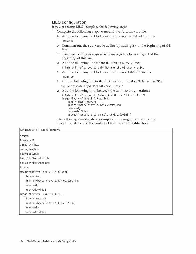
LILO configurationIf you are using LILO, complete the following steps:1. Complete the following steps to modify the /etc/lilo.conf file:
a. Add the following text to the end of the first default=linux line:-Monitor
b. Comment out the map=/boot/map line by adding a # at the beginning of thisline.
c. Comment out the message=/boot/message line by adding a # at thebeginning of this line.
d. Add the following line before the first image=... line:# This will allow you to only Monitor the OS boot via SOL
e. Add the following text to the end of the first label=linux line:-Monitor
f. Add the following line to the first image=... section. This enables SOL.append="console=ttyS1,19200n8 console=tty1"
g. Add the following lines between the two image=... sections:# This will allow you to Interact with the OS boot via SOLimage=/boot/vmlinuz-2.4.9-e.12smp
label=linux-Interactinitrd=/boot/initrd-2.4.9-e.12smp.imgread-onlyroot=/dev/hda6append="console=tty1 console=ttyS1,19200n8 "
The following samples show examples of the original content of the/etc/lilo.conf file and the content of this file after modification.
Original /etc/lilo.conf contents
prompt
timeout=50
default=linux
boot=/dev/hda
map=/boot/map
install=/boot/boot.b
message=/boot/message
linear
image=/boot/vmlinuz-2.4.9-e.12smp
label=linux
initrd=/boot/initrd-2.4.9-e.12smp.img
read-only
root=/dev/hda6
image=/boot/vmlinuz-2.4.9-e.12
label=linux-up
initrd=/boot/initrd-2.4.9-e.12.img
read-only
root=/dev/hda6
16 BladeCenter: Serial over LAN Setup Guide
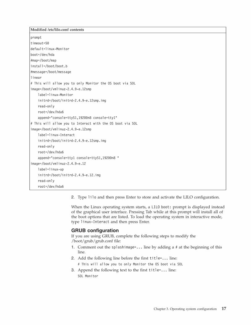
Modified /etc/lilo.conf contents
prompt
timeout=50
default=linux-Monitor
boot=/dev/hda
#map=/boot/map
install=/boot/boot.b
#message=/boot/message
linear
# This will allow you to only Monitor the OS boot via SOL
image=/boot/vmlinuz-2.4.9-e.12smp
label=linux-Monitor
initrd=/boot/initrd-2.4.9-e.12smp.img
read-only
root=/dev/hda6
append="console=ttyS1,19200n8 console=tty1"
# This will allow you to Interact with the OS boot via SOL
image=/boot/vmlinuz-2.4.9-e.12smp
label=linux-Interact
initrd=/boot/initrd-2.4.9-e.12smp.img
read-only
root=/dev/hda6
append="console=tty1 console=ttyS1,19200n8 "
image=/boot/vmlinuz-2.4.9-e.12
label=linux-up
initrd=/boot/initrd-2.4.9-e.12.img
read-only
root=/dev/hda6
2. Type lilo and then press Enter to store and activate the LILO configuration.
When the Linux operating system starts, a LILO boot: prompt is displayed insteadof the graphical user interface. Pressing Tab while at this prompt will install all ofthe boot options that are listed. To load the operating system in interactive mode,type linux-Interact and then press Enter.
GRUB configurationIf you are using GRUB, complete the following steps to modify the/boot/grub/grub.conf file:1. Comment out the splashimage=... line by adding a # at the beginning of this
line.2. Add the following line before the first title=... line:
# This will allow you to only Monitor the OS boot via SOL
3. Append the following text to the first title=... line:SOL Monitor
Chapter 3. Operating system configuration 17

4. Append the following text to the kernel/... line of the first title=... section:console=ttyS1,19200 console=tty1
5. Add the following lines between the two title=... sections:# This will allow you to Interact with the OS boot via SOLtitle Red Hat Linux (2.4.9-e.12smp) SOL Interactive
root (hd0,0)kernel /vmlinuz-2.4.9-e.12smp ro root=/dev/hda6 console=tty1
console=ttyS1,19200initrd /initrd-2.4.9-e.12smp.img
Note: The entry beginning with kernel /vmlinuz... is shown with a line breakafter console=tty1. In your file, the entire entry must all be on one line.
The following samples show examples of the original content of the/boot/grub/grub.conf file and the content of this file after modification.
Original /boot/grub/grub.conf contents
#grub.conf generated by anaconda
#
# Note that you do not have to rerun grub after making changes to this file
# NOTICE: You have a /boot partition. This means that
# all kernel and initrd paths are relative to /boot/, eg.
# root (hd0,0)
# kernel /vmlinuz-version ro root=/dev/hda6
# initrd /initrd-version.img
#boot=/dev/hda
default=0
timeout=10
splashimage=(hd0,0)/grub/splash.xpm.gz
title Red Hat Enterprise Linux ES (2.4.9-e.12smp)
root (hd0,0)
kernel /vmlinuz-2.4.9-e.12smp ro root=/dev/hda6
initrd /initrd-2.4.9-e.12smp.img
title Red Hat Enterprise Linux ES-up (2.4.9-e.12)
root (hd0,0)
kernel /vmlinuz-2.4.9-e.12 ro root=/dev/hda6
initrd /initrd-2.4.9-e.12.img
18 BladeCenter: Serial over LAN Setup Guide
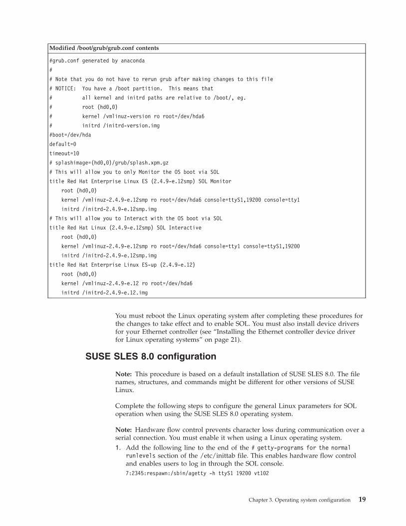
Modified /boot/grub/grub.conf contents
#grub.conf generated by anaconda
#
# Note that you do not have to rerun grub after making changes to this file
# NOTICE: You have a /boot partition. This means that
# all kernel and initrd paths are relative to /boot/, eg.
# root (hd0,0)
# kernel /vmlinuz-version ro root=/dev/hda6
# initrd /initrd-version.img
#boot=/dev/hda
default=0
timeout=10
# splashimage=(hd0,0)/grub/splash.xpm.gz
# This will allow you to only Monitor the OS boot via SOL
title Red Hat Enterprise Linux ES (2.4.9-e.12smp) SOL Monitor
root (hd0,0)
kernel /vmlinuz-2.4.9-e.12smp ro root=/dev/hda6 console=ttyS1,19200 console=tty1
initrd /initrd-2.4.9-e.12smp.img
# This will allow you to Interact with the OS boot via SOL
title Red Hat Linux (2.4.9-e.12smp) SOL Interactive
root (hd0,0)
kernel /vmlinuz-2.4.9-e.12smp ro root=/dev/hda6 console=tty1 console=ttyS1,19200
initrd /initrd-2.4.9-e.12smp.img
title Red Hat Enterprise Linux ES-up (2.4.9-e.12)
root (hd0,0)
kernel /vmlinuz-2.4.9-e.12 ro root=/dev/hda6
initrd /initrd-2.4.9-e.12.img
You must reboot the Linux operating system after completing these procedures forthe changes to take effect and to enable SOL. You must also install device driversfor your Ethernet controller (see “Installing the Ethernet controller device driverfor Linux operating systems” on page 21).
SUSE SLES 8.0 configuration
Note: This procedure is based on a default installation of SUSE SLES 8.0. The filenames, structures, and commands might be different for other versions of SUSELinux.
Complete the following steps to configure the general Linux parameters for SOLoperation when using the SUSE SLES 8.0 operating system.
Note: Hardware flow control prevents character loss during communication over aserial connection. You must enable it when using a Linux operating system.1. Add the following line to the end of the # getty-programs for the normal
runlevels section of the /etc/inittab file. This enables hardware flow controland enables users to log in through the SOL console.7:2345:respawn:/sbin/agetty -h ttyS1 19200 vt102
Chapter 3. Operating system configuration 19
2. Add the following line after the tty6 line at the bottom of the /etc/securettyfile to enable a user to log in as the root user through the SOL console:ttyS1
3. Complete the following steps to modify the /boot/grub/menu.lst file:a. Comment out the gfxmenu... line by adding a # at the beginning of the
line.b. Add the following line before the first title... line:
# This will allow you to only Monitor the OS boot via SOL
c. Add the following text to the end of the first title... line:SOL Monitor
d. Add the following text to the end of the kernel... line of the first title...section:console=ttyS1,19200 console=tty1
e. Add the following lines between the first two title... sections:# This will allow you to Interact with the OS boot via SOLtitle linux SOL Interactive
kernel (hd0,1)/boot/vmlinuz root=/dev/hda2 acpi=oldboot vga=791console=tty1 console=ttyS1,19200
initrd (hd0,1)/boot/initrd
Note: The entry beginning with kernel (hd0,1) is shown with a line break aftervga=791. In your file, the entire entry must all be on one line.
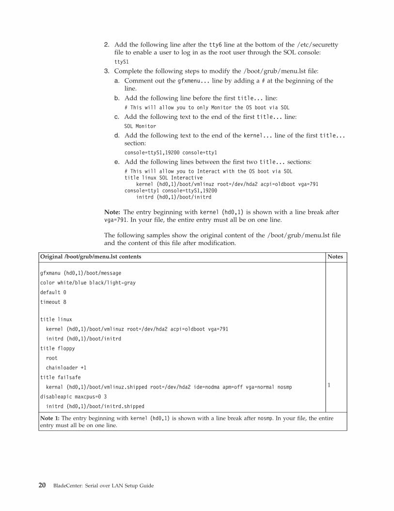
The following samples show the original content of the /boot/grub/menu.lst fileand the content of this file after modification.
Original /boot/grub/menu.lst contents Notes
gfxmanu (hd0,1)/boot/message
color white/blue black/light-gray
default 0
timeout 8
title linux
kernel (hd0,1)/boot/vmlinuz root=/dev/hda2 acpi=oldboot vga=791
initrd (hd0,1)/boot/initrd
title floppy
root
chainloader +1
title failsafe
kernal (hd0,1)/boot/vmlinuz.shipped root=/dev/hda2 ide=nodma apm=off vga=normal nosmp 1
disableapic maxcpus=0 3
initrd (hd0,1)/boot/initrd.shipped
Note 1: The entry beginning with kernel (hd0,1) is shown with a line break after nosmp. In your file, the entireentry must all be on one line.
20 BladeCenter: Serial over LAN Setup Guide
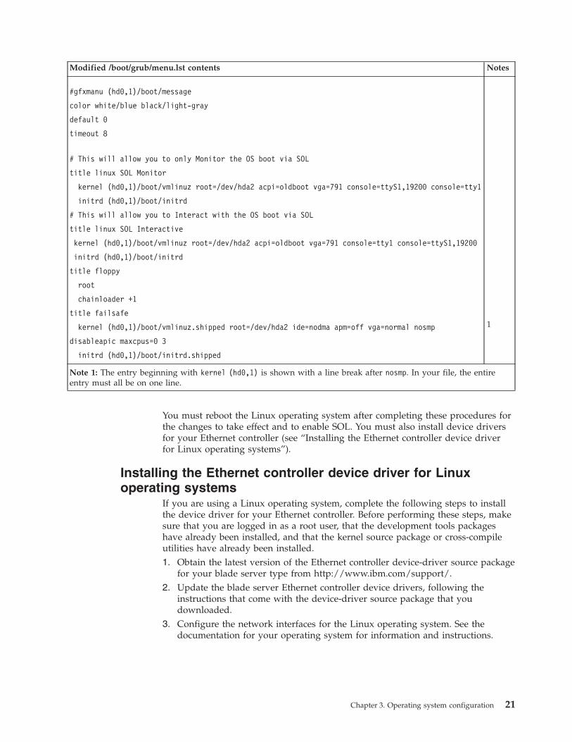
Modified /boot/grub/menu.lst contents Notes
#gfxmanu (hd0,1)/boot/message
color white/blue black/light-gray
default 0
timeout 8
# This will allow you to only Monitor the OS boot via SOL
title linux SOL Monitor
kernel (hd0,1)/boot/vmlinuz root=/dev/hda2 acpi=oldboot vga=791 console=ttyS1,19200 console=tty1
initrd (hd0,1)/boot/initrd
# This will allow you to Interact with the OS boot via SOL
title linux SOL Interactive
kernel (hd0,1)/boot/vmlinuz root=/dev/hda2 acpi=oldboot vga=791 console=tty1 console=ttyS1,19200
initrd (hd0,1)/boot/initrd
title floppy
root
chainloader +1
title failsafe
kernel (hd0,1)/boot/vmlinuz.shipped root=/dev/hda2 ide=nodma apm=off vga=normal nosmp 1
disableapic maxcpus=0 3
initrd (hd0,1)/boot/initrd.shipped
Note 1: The entry beginning with kernel (hd0,1) is shown with a line break after nosmp. In your file, the entireentry must all be on one line.
You must reboot the Linux operating system after completing these procedures forthe changes to take effect and to enable SOL. You must also install device driversfor your Ethernet controller (see “Installing the Ethernet controller device driverfor Linux operating systems”).
Installing the Ethernet controller device driver for Linuxoperating systems
If you are using a Linux operating system, complete the following steps to installthe device driver for your Ethernet controller. Before performing these steps, makesure that you are logged in as a root user, that the development tools packageshave already been installed, and that the kernel source package or cross-compileutilities have already been installed.1. Obtain the latest version of the Ethernet controller device-driver source package
for your blade server type from http://www.ibm.com/support/.2. Update the blade server Ethernet controller device drivers, following the
instructions that come with the device-driver source package that youdownloaded.
3. Configure the network interfaces for the Linux operating system. See thedocumentation for your operating system for information and instructions.
Chapter 3. Operating system configuration 21
Microsoft Windows 2003 Standard Edition configuration
Note: This procedure is based on a default installation of the Microsoft Windows2003 operating system.
Complete the following steps to configure the Windows 2003 operating system forSOL operation. You must be logged in as a user with administrator access toperform this procedure.1. Complete the following steps to determine which boot entry ID to modify:
a. Type bootcfg at a Windows command prompt; then press Enter to displaythe current boot options for your system.
b. In the Boot Entries section, locate the Boot entry ID for the section with anOS friendly name of Windows Server 2003, Standard. Write down the Bootentry ID that appears above this line for use in the next step.
2. To enable the Microsoft Windows Emergency Management System (EMS), at aWindows command prompt, type bootcfg /EMS ON /PORT COM2 /BAUD 19200/ID boot_id where boot_id is the boot entry ID from step 1b; then, press Enter.
3. Complete the following steps to verify that the EMS console is redirected to theCOM2 serial port:a. Type bootcfg at a Windows command prompt; then, press Enter to display
the current boot options for your system.b. Verify the following changes to the bootcfg settings:
v In the Boot Loader Settings section, make sure that redirect is set toCOM2 and that redirectbaudrate is set to 19200.
v In the Boot Entries section, make sure that the OS Load Options: line has/redirect appended to the end of it.
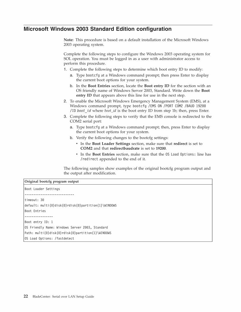
The following samples show examples of the original bootcfg program output andthe output after modification.
Original bootcfg program output
Boot Loader Settings
----------------------------
timeout: 30
default: multi(0)disk(0)rdisk(0)partition(1)\WINDOWS
Boot Entries
----------------
Boot entry ID: 1
OS Friendly Name: Windows Server 2003, Standard
Path: multi(0)disk(0)rdisk(0)partition(1)\WINDOWS
OS Load Options: /fastdetect
22 BladeCenter: Serial over LAN Setup Guide
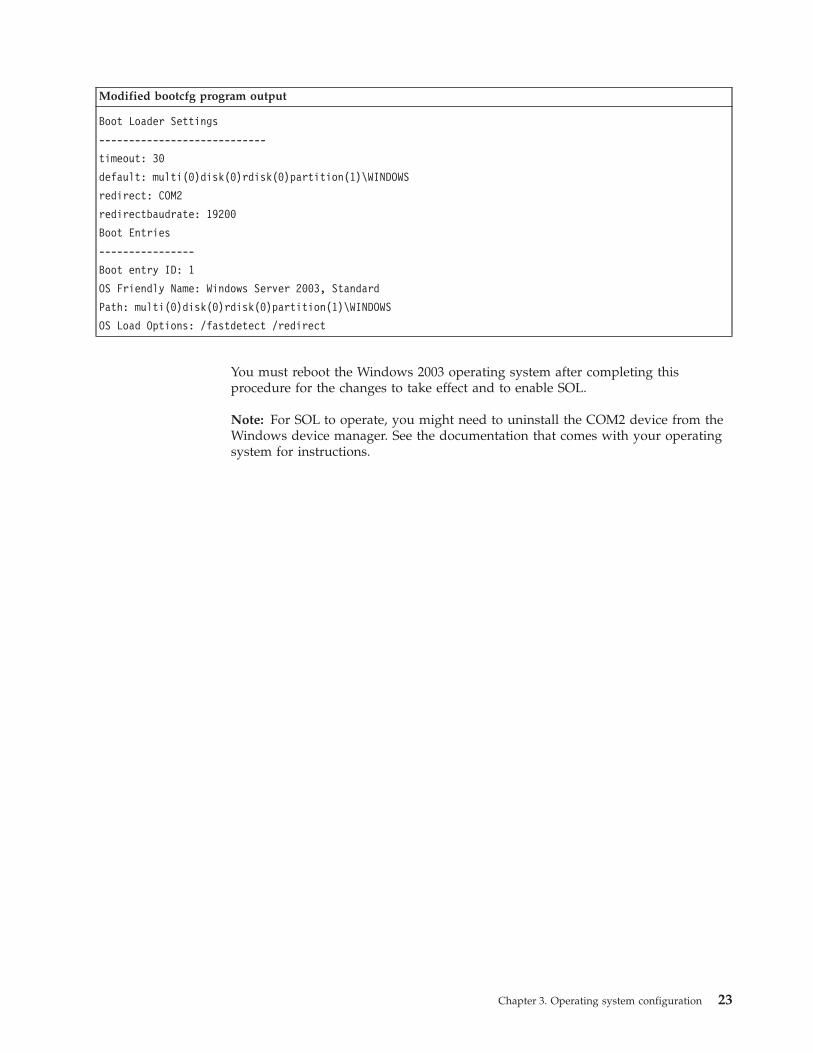
Modified bootcfg program output
Boot Loader Settings
----------------------------
timeout: 30
default: multi(0)disk(0)rdisk(0)partition(1)\WINDOWS
redirect: COM2
redirectbaudrate: 19200
Boot Entries
----------------
Boot entry ID: 1
OS Friendly Name: Windows Server 2003, Standard
Path: multi(0)disk(0)rdisk(0)partition(1)\WINDOWS
OS Load Options: /fastdetect /redirect
You must reboot the Windows 2003 operating system after completing thisprocedure for the changes to take effect and to enable SOL.
Note: For SOL to operate, you might need to uninstall the COM2 device from theWindows device manager. See the documentation that comes with your operatingsystem for instructions.
Chapter 3. Operating system configuration 23

24 BladeCenter: Serial over LAN Setup Guide

Chapter 4. Special component requirements
Most BladeCenter components are pre-configured for SOL operation. SomeBladeCenter components must be configured to support SOL operation. Thissection provides instructions for configuring BladeCenter components for SOLoperation. It also provides information that is needed when connecting certaincomponents for SOL operation. Use this information in addition to the informationin Chapter 2, “General configuration,” on page 7 and Chapter 3, “Operating systemconfiguration,” on page 15. This section is divided into the following subsections:
Special blade server configuration requirements:v “Configuring the BladeCenter HS22 Type 7870 blade server”v “Configuring the BladeCenter HS20 Type 8832 and HS20 Type 8843 blade
servers” on page 27v “Configuring the BladeCenter HS40 Type 8839 blade server” on page 29v “Configuring the BladeCenter JS20 Type 8842 blade server” on page 30
Special I/O-module configuration and connection requirements:v “Configuring the IBM 4-Port Gb Ethernet Switch Module for BladeCenter” on
page 32v “Configuring the Nortel Networks Layer 2-7 GbE Switch Module for IBM
BladeCenter” on page 33v “Configuring the Cisco Systems Intelligent Gigabit Ethernet Switch Module for
the IBM BladeCenter” on page 34v “Connecting an Intelligent Copper Pass-thru Module” on page 35
Configuring the BladeCenter HS22 Type 7870 blade serverComplete the following steps to configure the HS22 Type 7870 blade server forSOL operation. See the IBM BladeCenter HS22 Type 7870 Installation and User’s Guidefor additional information relating to these steps.1. Obtain the latest versions of HS22 Type 7870 blade server firmware from
http://www.ibm.com/support/.2. Update the HS22 Type 7870 blade server firmware, following the instructions
that come with the update file that you downloaded. The HS22 Type 7870blade server has multiple firmware images. Make sure that you restart theblade server after updating each firmware image.
3. Make sure that you have configured the BladeCenter unit and the operatingsystem for SOL operation, following the instructions in Chapter 2, “Generalconfiguration,” on page 7 and Chapter 3, “Operating system configuration,”on page 15.
4. Restart the blade server and immediately give the blade server control of theBladeCenter unit shared keyboard, video, and mouse ports.v If you are managing the blade server by using the BladeCenter system
console, press the KVM select button on the blade server.v If you are managing the blade server from a remote location, see the IBM
BladeCenter Management Module User’s Guide or IBM BladeCenter ManagementModule Command-Line Interface Reference Guide for information andinstructions.
© Copyright IBM Corp. 2009 25

5. When the prompt Press <F1> Setup is displayed, press F1. If you have set anadministrator password, you must type the administrator password to accessthe full Setup-utility menu. If you do not type the administrator password, alimited Setup-utility menu is available.
6. Select System Settings and then press Enter.7. Select Devices and I/O Ports and then press Enter.8. Select Console Redirection Settings and then press Enter.9. From the Console Redirection Settings menu:
a. If you are using a serial breakout cable with a BladeCenter H unit or aBladeCenter S unit, set COM Port 1 to Enable; otherwise, set it to Disable.
b. Set COM Port 2 to Enable.c. Set Remote Console to Enable.d. Set Legacy Option ROM Display to COM Port 2.e. Set the following COM2 Settings:
1) Make sure that the Baud Rate is set to 115200.
Note: The settings for Data Bits, Parity, and Stop Bits are static andcannot be changed.
2) Set Terminal Emulation to ANSI (default) or VT100, depending onyour system configuration.
3) Set Active After Boot to Enable.4) Set Flow Control to Hardware.
26 BladeCenter: Serial over LAN Setup Guide

10. Press Esc four times; then, press Y, when prompted, to save settings andrestart the blade server.
After the blade server has restarted, you can establish an SOL session to it usingthe advanced management module CLI. See “Starting an SOL session” on page 37for information and instructions.
Configuring the BladeCenter HS20 Type 8832 and HS20 Type 8843blade servers
Note: If an SOL session for the BladeCenter HS20 Type 8832 or Type 8843 bladeserver displays only a flashing cursor in a blank screen, this indicates aninterruption in the flow of serial data. Press Ctrl+q to resume serial data flow.
The following sections describe the SOL configuration that is required for theBladeCenter HS20 Type 8832 and Type 8843 blade servers. You must perform thefollowing procedures:v “HS20 Type 8832 SOL jumper placement” on page 28 (Type 8832 blade server
only)v “Updating and configuring the blade server BIOS” on page 13v “Updating the integrated systems management processor firmware” on page 28v “Updating the Broadcom Ethernet controller firmware” on page 29v “Installing the Ethernet controller device driver for Linux operating systems” on
page 21
Chapter 4. Special component requirements 27

HS20 Type 8832 SOL jumper placementFor SOL operation with the HS20 Type 8832 blade server, jumper J28 on the bladeserver must be installed on pins 2 and 3. This is the default jumper position thatdirects SOL data to I/O-module bay 1 in the BladeCenter unit.
I/O-module baySOL select
(J28)
12
34
56
78
OF
F
321
321
2 - 3I/O-module
bay 1
1 - 2I/O-module
bay 2
Updating the integrated systems management processorfirmware
Note: Make sure that the blade server BIOS is upgraded and configured beforeyou update the integrated systems management processor firmware (see“Updating and configuring the blade server BIOS” on page 13).
Complete the following procedure to update the BladeCenter HS20 Type 8832 orType 8843 blade server integrated systems management processor (ISMP)firmware. No configuration is required for the BladeCenter HS20 Type 8832 orType 8843 blade server ISMP to enable SOL.
Attention: Do not change the BladeCenter media tray owner by pressing thebutton on the front of the blade server or through the BladeCentermanagement-module Web interface while the ISMP firmware update is in progress.This will interrupt the update procedure and might damage the blade server.
Complete the following steps to update the BladeCenter HS20 Type 8832 or Type8843 blade server ISMP firmware:1. Download the latest version of ISMP firmware for your blade server type from
http://www.ibm.com/support/.2. Update the blade server ISMP firmware, following the instructions that come
with the update file that you downloaded. To update the blade server ISMPfirmware click Blade Tasks → Firmware Update in the BladeCentermanagement-module Web interface or use an update diskette.
28 BladeCenter: Serial over LAN Setup Guide
Updating the Broadcom Ethernet controller firmwareThe Broadcom Ethernet controller on the BladeCenter HS20 Type 8832 and Type8843 blade servers has the following requirements for SOL operation:v An SOL capable Ethernet I/O module must be installed in I/O module bay 1 of
the BladeCenter unit (see “Hardware and firmware requirements” on page 2).v For the BladeCenter HS20 Type 8832 blade server, the SOL jumper J28 must be
placed on pins 2 and 3. This is the default jumper position. See “HS20 Type 8832SOL jumper placement” on page 28.
Complete the following steps to update the BladeCenter HS20 Type 8832 or Type8843 blade server Broadcom Ethernet controller firmware. You do not have toconfigure the Broadcom Ethernet Controllers to enable SOL.1. Download the latest version of Broadcom Ethernet controller firmware for your
blade server type from http://www.ibm.com/support/.2. Update the blade server Broadcom Ethernet controller firmware, following the
instructions that come with the update file that you downloaded. To update theblade server Broadcom Ethernet controller firmware, use an update diskette oruse the Broadcom Ethernet controller diagnostic utility, depending on theoperating system that is installed on your blade server.
Configuring the BladeCenter HS40 Type 8839 blade serverThe following sections describe the SOL configuration that is required for theBladeCenter HS40 Type 8839 blade server. You must perform the followingprocedures:v “Updating the Baseboard Management Controller firmware”v “Updating and configuring the BIOS” on page 30v “Installing the Ethernet controller device driver for Linux operating systems” on
page 21
Updating the Baseboard Management Controller firmwareNo configuration is required for the BladeCenter HS40 Type 8839 blade serverBMC to enable SOL.
Complete the following steps to update the BladeCenter HS40 Type 8839 bladeserver BMC firmware:1. Download the latest version of BladeCenter HS40 Type 8839 blade server BMC
firmware from http://www.ibm.com/support/.2. Update the blade server BMC firmware, following the instructions that come
with the update images that you downloaded. To update the blade server BMCfirmware, use an update diskette.
Chapter 4. Special component requirements 29
Updating and configuring the BIOS
Important: The BladeCenter HS40 Type 8839 blade server BMC firmware must beupdated before you update the BIOS firmware.
Complete the following steps to update and configure the BladeCenter HS40 Type8839 blade server BIOS to enable SOL:1. Complete the following steps to update the BladeCenter HS40 Type 8839 blade
server BIOS:a. Download the latest version of BladeCenter HS40 Type 8839 blade server
BIOS from http://www.ibm.com/support/.b. Update the blade server BIOS, following the instructions that come with the
update images that you downloaded.2. Complete the following steps to configure the BladeCenter HS40 Type 8839
blade server BIOS settings:a. Restart the blade server and press F1 when prompted to start the
Configuration/Setup Utility program.b. Select Devices and I/O Ports; then, make sure that the Serial Ports value is
set to Enabled
c. Select Remote Console Redirection; then, make sure that the values are setas follows:
Note: For newer versions of HS40 Type 8839 BIOS, the BIOS RedirectionPort is set to a fixed value of Serial 2 and cannot be changed.v BIOS Redirection Port: Serial 2v Baud Rate: 19.2Kv Flow Control: CTS/RTSv Terminal Type: VT100+
d. Press Esc twice to exit the Remote Console Redirection and Devices andI/O Ports sections of the Configuration/Setup Utility program.
e. Press F10.f. Make sure that OK is selected; then, press Enter.
3. Remove the blade server from the BladeCenter unit and then reinstall it. Seethe Installation and User’s Guide for your blade server for instructions.
Configuring the BladeCenter JS20 Type 8842 blade serverNo manual configuration of the BladeCenter JS20 Type 8842 blade server openfirmware (BIOS) or ISMP is required. This blade server automatically configuresitself when you install it in the BladeCenter unit and is automatically reconfiguredafter you install new software or hardware. The BladeCenter JS20 Type 8842 bladeserver has built-in support for the SOL feature. You must install the BroadcomEthernet controller device driver after you install the blade server operatingsystem.
You must use the SOL feature to initially install and configure the operatingsystem in the BladeCenter JS20 Type 8842 blade server. After the operating systemhas been completely installed and configured, you can use either Telnet or SSHsessions to communicate directly with the blade server operating system.
Note: The Broadcom Ethernet controller on the BladeCenter JS20 Type 8842 bladeserver might be unable to communicate for a few seconds while the blade server is
30 BladeCenter: Serial over LAN Setup Guide

restarting. If this occurs, the current SOL session will be terminated; however, theSOL session can be established again after the blade server restarts.
The following sections describe how to set up SOL for the BladeCenter JS20 Type8842 blade server. You must perform the following procedures:v “Updating the open firmware (BIOS)”v “Updating the integrated systems management processor firmware”v “Updating the Broadcom Ethernet controller firmware” on page 32v “Installing the Ethernet controller device driver for Linux operating systems” on
page 21
Updating the open firmware (BIOS)
Notes:
1. The Linux operating system must be installed and configured before updatingBIOS.
2. You must be logged in as a root user to perform these procedures.3. If an SOL session is in progress, it will be terminated when the BladeCenter
JS20 Type 8842 blade server open firmware is updated. The SOL session can beestablished again after the firmware update is complete.
Complete the following steps to update the BladeCenter JS20 Type 8842 bladeserver open firmware. You do not have to configure the blade server openfirmware to enable SOL.1. Download the latest version of BladeCenter JS20 Type 8842 blade server open
firmware from http://www.ibm.com/support/.2. Update the blade server open firmware, following the instructions that come
with the update file that you downloaded.
Updating the integrated systems management processorfirmware
Attention: Do not change the BladeCenter media tray owner by pressing thebutton on the front of the blade server or through the BladeCentermanagement-module Web interface while the integrated systems managementprocessor (ISMP) firmware update is in progress. This will interrupt the updateprocedure and might damage the BladeCenter JS20 Type 8842 blade server.
Important: You must update the open firmware (BIOS) on the BladeCenter JS20Type 8842 blade server before you update the ISMP firmware.
Complete the following steps to update the BladeCenter JS20 Type 8842 bladeserver ISMP firmware. You do not have to configure the ISMP to enable SOL.1. Download the latest version of BladeCenter JS20 Type 8842 blade server ISMP
firmware from http://www.ibm.com/support/.2. Update the blade server ISMP firmware, following the instructions that come
with the update file that you downloaded. To update the blade server ISMPfirmware, click Blade Tasks → Firmware Update in the BladeCentermanagement-module Web interface.
Chapter 4. Special component requirements 31

Updating the Broadcom Ethernet controller firmware
Notes:
1. The Linux operating system must be installed and configured before updatingthe Broadcom Ethernet controller firmware.
2. You must be logged in as a root user to perform these procedures.
The Broadcom Ethernet controller on the BladeCenter JS20 Type 8842 blade serverhas the following requirements for SOL operation:v An SOL capable Ethernet I/O module must be installed in I/O module bay 1 of
the BladeCenter unit (see “Hardware and firmware requirements” on page 2).v You must not have any other Broadcom Ethernet Controller devices, such as the
BladeCenter Gigabit Ethernet Expansion Card, activated.v The latest Broadcom Ethernet controller network device driver must be installed
and both Ethernet interfaces (eth0 and eth1) must be configured before you usethe Broadcom Ethernet controller diagnostic utility.
Complete the following steps to update the BladeCenter JS20 Type 8842 bladeserver Broadcom Ethernet controller firmware. You do not have to configure theBroadcom Ethernet controllers to enable SOL.1. Download the latest version of BladeCenter JS20 Type 8842 blade server
Broadcom Ethernet controller firmware from http://www.ibm.com/support/.2. Update the blade server Broadcom Ethernet controller firmware, following the
instructions that come with the update file that you downloaded.
After installing the Broadcom Ethernet controller firmware, you must restart theblade server before you can use the SOL feature.
Configuring the IBM 4-Port Gb Ethernet Switch Module for BladeCenterComplete the following steps to update the firmware of the IBM 4-Port GbEthernet Switch Module for BladeCenter. No configuration is required for the IBM4-Port Gb Ethernet Switch Module for BladeCenter to enable SOL.
Note:
1. You will not be able to perform this procedure if the values for the networkconfiguration of the IBM 4-Port Gb Ethernet Switch Module for BladeCenter arenot within the same subnet as the BladeCenter management-module networkinterfaces (eth0 and eth1). See “Configuring the management module” on page9 for information.
2. If you are using management channel auto discovery (MCAD), replacereferences to I/O-module bay 1 in the following procedure with the I/Omodule bay number that is actually being used (see the BladeCenter AdvancedManagement Module User's Guide for additional information about MCAD).
1. Obtain the latest version of IBM 4-Port Gb Ethernet Switch Module forBladeCenter firmware from http://www.ibm.com/support/.
2. Start the BladeCenter management-module Web interface (see “Starting theBladeCenter management-module Web interface” on page 5).
3. In the navigation pane, click I/O Module Tasks → Configuration.4. Scroll to the Current IP Configuration section and make sure that it contains
values that are within the same subnet as the BladeCentermanagement-module network interfaces (eth0 and eth1). If the values are not
32 BladeCenter: Serial over LAN Setup Guide
in the same subnet, you must modify them before you continue. See“Configuring the management module” on page 9 for information.
5. Scroll to the Bay 1 (Ethernet SM)* section; then, click AdvancedManagement.
6. Scroll to the Start Telnet/Web Session section; then, click Start Web Session.This will start a new Web browser session and connect to the IBM 4-Port GbEthernet Switch Module for BladeCenter Web interface.
7. Log in to the IBM 4-Port Gb Ethernet Switch Module for BladeCenter Webinterface.
8. Click Maintenance.9. Click Using Browser.
10. Click Upgrade Firmware/Configuration.11. Click Browse; then, select the firmware update file that you obtained in step 1.12. Click Start; then, click Yes to confirm each time you are asked a question.13. Close the Web browser.14. Complete the following steps to restart the I/O module:
a. In the navigation pane, click I/O Module Tasks → Admin/Power/Restart.b. Select your IBM 4-Port Gb Ethernet Switch Module for BladeCenter and
click Restart Module(s) and Run Standard Diagnostics.c. Click OK to confirm.
Configuring the Nortel Networks Layer 2-7 GbE Switch Module for IBMBladeCenter
Complete the following steps to update the firmware of the Nortel Networks Layer2-7 GbE Switch Module for IBM BladeCenter. No configuration is required for theNortel Networks Layer 2-7 GbE Switch Module for IBM BladeCenter to enableSOL.
Notes:
v You will not be able to perform this procedure if the values for the networkconfiguration of the Nortel Networks Layer 2-7 GbE Switch Module for IBMBladeCenter are not within the same subnet as the BladeCentermanagement-module network interfaces (eth0 and eth1). See “Configuring themanagement module” on page 9 for information.
v These steps require that an accessible TFTP (Trivial FTP) server is present onyour production network.
1. Obtain the latest version of Nortel Networks Layer 2-7 GbE Switch Module forIBM BladeCenter firmware from http://www.ibm.com/support/.
2. Update the Nortel Networks Layer 2-7 GbE Switch Module for IBMBladeCenter firmware, following the instructions that come with the update filethat you downloaded. The Nortel Networks Layer 2-7 GbE Switch Module hasmultiple firmware images. These images must all be updated, in the correctorder. Make sure that you restart the Nortel Networks Layer 2-7 GbE SwitchModule after updating each firmware image.
Chapter 4. Special component requirements 33
Configuring the Cisco Systems Intelligent Gigabit Ethernet SwitchModule for the IBM BladeCenter
Note: For Cisco IOS release 12.1(22)EA6a and later, the SOL VLAN ID is set to adefault value of 4095. If you use the default SOL VLAN ID of 4095, no additionalconfiguration of the Cisco Systems Intelligent Gigabit Ethernet Switch Module isrequired. You need to complete the following procedure if you set a custom SOLVLAN ID.
Complete the following steps to configure the Cisco Systems Intelligent GigabitEthernet Switch Module for the IBM BladeCenter. The Cisco Systems IntelligentGigabit Ethernet Switch Module has built-in support for the SOL feature and doesnot require a firmware upgrade.
Note:
1. You will not be able to perform this procedure if the values for the networkconfiguration of the Cisco Systems Intelligent Gigabit Ethernet Switch Moduleare not within the same subnet as the BladeCenter management-modulenetwork interfaces (eth0 and eth1). See “Configuring the management module”on page 9 for information.
2. If you are using management channel auto discovery (MCAD), replacereferences to I/O-module bay 1 in the following procedure with the I/Omodule bay number that is actually being used (see the BladeCenter AdvancedManagement Module User's Guide for additional information about MCAD).
1. Start the BladeCenter management-module Web interface (see “Starting theBladeCenter management-module Web interface” on page 5).
2. In the navigation pane, click I/O Module Tasks → Configuration.3. Scroll to the Current IP Configuration section and make sure that it contains
values that are within the same subnet as the BladeCentermanagement-module network interfaces (eth0 and eth1). If the values are notin the same subnet, you must modify them before you continue. See“Configuring the management module” on page 9 for information.
4. Scroll to the Bay 1 (Ethernet SM)* section; then, click AdvancedManagement.
5. Scroll to the Start Telnet/Web Session section; then, click Start Telnet Session.This will start a new Telnet session and connect to the Cisco SystemsIntelligent Gigabit Ethernet Switch Module Telnet interface.
6. Log in to the Cisco Systems Intelligent Gigabit Ethernet Switch Module Telnetinterface.
7. Complete the following steps to activate the VLAN ID for the Cisco SystemsIntelligent Gigabit Ethernet Switch Module:a. Type en and then press Enter.b. Type config t and then press Enter.c. Type vlan vlan_id, where vlan_id is the VLAN ID that was set for the
management module (see “Configuring the global SOL settings for theBladeCenter unit” on page 7); then, press Enter.
d. Type state active and then press Enter.e. Type end and then press Enter.f. Type wri and then press Enter.
34 BladeCenter: Serial over LAN Setup Guide

Attention: To maintain system security, you must remove the SOL VLAN IDfrom the external ports of the Cisco Systems Intelligent Gigabit EthernetSwitch Module.
8. Complete the following steps to remove the SOL VLAN ID from the externalports of the Cisco Systems Intelligent Gigabit Ethernet Switch Module:a. Type config t and then press Enter.b. Type int gi0/port_number , where port_number is an external port number
from 17 through 20 for the switch module; then, press Enter.c. Type switchport trunk allowed vlan remove vlan_id, where vlan_id is the
VLAN ID that was set in step 7c on page 34 (4095, by default); then, pressEnter.
d. Repeat step 8b and 8c for each external port number from 17 through 20.e. Type end and then press Enter.f. Type wri and then press Enter.
Note: For SOL operation with Cisco IOS releases earlier than 12.1(22)EA6a,the internal interfaces of the Cisco Ethernet Switch Module must be set totrunk mode. Trunk mode is the default configuration. If SOL sessions do notgo into a Ready state and you are using Cisco IOS releases earlier than12.1(22)EA6a, perform the procedure in step 9 to configure trunk mode.
9. Complete the following steps to configure the internal interfaces of the CiscoSystems Intelligent Gigabit Ethernet Switch Module for trunk mode:a. Type config t and then press Enter.b. Type int gi0/port_number , where port_number is an external port number
from 1 through 14 for the switch module; then, press Enter.c. Type switchport mode trunk and then, press Enter.d. Repeat step 9b and 9c for each external port number from 1 through 14.e. Type exit and then press Enter.f. Type int gi0/port_number , where port_number is an external port number
from 1 through 16 for the switch module; then, press Enter.g. Type sw trunk allow vlan add vlan_id, where vlan_id is the VLAN ID
that was set in step 7c on page 34; then, press Enter.h. Repeat step 9f and 9g for each external port number from 1 through 16.i. Type end and then press Enter.j. Type wri and then press Enter.
10. Type exit and then press Enter to close the Cisco Systems Intelligent GigabitEthernet Switch Module Telnet interface session.
11. Close the window in which the Telnet session was running.
Connecting an Intelligent Copper Pass-thru ModuleFor SOL to function with an Intelligent Copper Pass-thru Module (ICPM), theexternal port corresponding to the blade server must have an Ethernet cableattached to it with a link to an upstream switch. For example, to support SOL forthe blade server in bay 2, you must plug an Ethernet cable into RJ-45 port 2 of theICPM and have this Ethernet cable connected to an upstream switch.
Chapter 4. Special component requirements 35

36 BladeCenter: Serial over LAN Setup Guide
Chapter 5. Using SOL
The BladeCenter management module command-line interface provides aconvenient method for entering commands that manage and monitor BladeCentercomponents. This section contains the following information about using thecommand-line interface:v “Starting an SOL session”v “Ending an SOL session” on page 40v “Monitoring SOL session status” on page 40v “Restarting a blade server through SOL” on page 43v “Mounting and unmounting media for Linux operating systems” on page 44
See the documentation for your operating system for information about commandsthat you can enter through an SOL connection.
Starting an SOL sessionStart an SOL session from a client computer through the management-modulecommand-line interface by establishing a Telnet connection to the IP address of themanagement module, by setting up a session with the management module serialport (advanced management module only), or by establishing a Secure Shell (SSH)connection. You can establish up to 20 separate Web interface, Telnet, serial(advanced management module only), or SSH sessions with a BladeCentermanagement module. For a BladeCenter unit, this enables you to have 14simultaneous SOL sessions active (one for each of up to 14 blade servers) with 6additional command-line interface sessions available for BladeCenter unitmanagement. For a BladeCenter T unit, this enables you to have 8 simultaneousSOL sessions active (one for each of up to 8 blade servers) with 12 additionalcommand-line interface sessions available for BladeCenter unit management. Seethe BladeCenter Management Module Command-Line Interface Reference Guide forinformation about the management-module command-line interface.
This section provides the following instructions:v “Starting a command-line Telnet connection” on page 38v “Establishing a serial connection” on page 38v “Starting a command-line Secure Shell (SSH) connection” on page 39v “Starting an SOL session from the command-line interface” on page 39
Note: When using a Microsoft Windows client to make an SOL connection to aserver running a Linux or Unix operating system, you might experience problemssuch as double command prompts or an inability to issue commands that executecorrectly. If this happens, change the terminal emulation software being used onthe Windows client to map the Enter key as a carriage return (hex 0x0D) instead ofthe carriage return and line feed combination. Linux and Unix operating systemsrequire only a carriage return to terminate commands in the CLI.
© Copyright IBM Corp. 2009 37

Starting a command-line Telnet connection
Note: If there is no Telnet or SOL traffic within the timeout interval specified inthe management module, the Telnet session and any SOL session associated withthis Telnet session will terminate. See the BladeCenter Management ModuleCommand-Line Interface Reference Guide for information about configuring the Telnetsession timeout value.
To log on to the management module using Telnet, complete the following steps:1. Open a command-line window on the network-management workstation, type
telnet 192.168.70.125, and press Enter. The IP address 192.168.70.125 is thedefault IP address of the management module; if a new IP address has beenassigned to the management module, use that one instead. You can alsosubstitute a valid host name instead of using an IP address.A command-prompt window opens.
2. At the login prompt, type the management-module user ID. At the passwordprompt, type the management-module password. The user ID and passwordare case sensitive and are the same as those that are used formanagement-module Web access. The default management-module user nameis USERID and the default password is PASSW0RD (note the number zero, notthe letter O, in PASSW0RD).A CLI command prompt is displayed. You can now enter commands for themanagement module.
Establishing a serial connectionAfter connecting a serial cable from the advanced management module to theclient computer, complete the following steps:1. Open a terminal session on the client computer, and make sure that the serial
port settings for the client computer match the settings for the serial port onthe advanced management module. The default advanced management-moduleserial port settings are as follows:v Baud rate: 57600v Parity: no parityv Stop bits: 1
2. At the login prompt, type the management-module user ID. At the passwordprompt, type the management-module password. The user ID and passwordare case sensitive and are the same as those that are used formanagement-module Web access. The default management-module user nameis USERID and the default password is PASSW0RD (note the number zero, notthe letter O, in PASSW0RD).
The CLI command prompt is displayed. You can now enter commands for themanagement module.
38 BladeCenter: Serial over LAN Setup Guide

Starting a command-line Secure Shell (SSH) connectionTo log on to the management module using SSH, complete the following steps:1. Make sure that the SSH service on the network-management workstation is
enabled. See your operating-system documentation for instructions.2. Make sure that the SSH server on the BladeCenter management module is
enabled. See the BladeCenter Management Module User’s Guide for instructions.3. Start a SSH session to the management module using the SSH client of your
choice. For example, if you are using the cygwin client, open a command-linewindow on the network-management workstation, type ssh -x192.168.70.125, and press Enter. The IP address 192.168.70.125 is the default IPaddress of the management module; if a new IP address has been assigned tothe management module, use that one instead.A command-prompt window opens.
4. Type the management-module user ID when prompted. At the passwordprompt, type the management-module password. The user ID and passwordare case sensitive and are the same as those that are used formanagement-module Web access. The default management-module user nameis USERID and the default password is PASSW0RD (note the number zero, notthe letter O, in PASSW0RD).A CLI command prompt is displayed. You can now enter commands for themanagement module.
Starting an SOL session from the command-line interfaceAfter an SOL session is started, all commands are sent to the operating system onthe blade server specified by the console command until the SOL session is ended,regardless of the persistent command target that was in effect before the SOLsession. During an SOL session, no BladeCenter command-line interface commandsare valid. If a blade server is restarted while an SOL session is in progress, the SOLsession remains in progress while the blade server restarts. Restarting themanagement module will end all SOL sessions that are running.
The BladeCenter management module automatically stores the previous 8 KB(kilobytes) of serial data that was transmitted by each blade server even when SOLsessions are not active. When an SOL session is established, all of the previousserial data, up to 8 KB, is automatically displayed. If no previous data is availablewhen the SOL session is started, the cursor will remain on the command line untilnew serial data is transmitted. If a management module fails, all Telnet and SOLsessions are terminated, and their caches are lost, even if failover to a redundantmanagement module is successful.
See the BladeCenter Management Module Command-Line Interface Reference Guide forinformation about configuring a blade server for SOL using the managementmodule command-line interface. See your operating-system documentation forinformation about commands that you can enter using an SOL command-lineinterface.
Note: Serial over LAN (SOL) must be enabled for both the BladeCenter unit andthe blade server before you can start an SOL session with the blade server. SeeChapter 2, “General configuration,” on page 7 and Chapter 4, “Special componentrequirements,” on page 25 for information about enabling SOL.
After you start a Telnet or SSH session to the BladeCenter management module(see the BladeCenter Management Module Command-Line Interface Reference Guide),
Chapter 5. Using SOL 39
you can start an SOL session to any individual blade server that supports SOLusing the console command. Because you can start up to 20 separate Webinterface, Telnet, serial (advanced management module only), or SSH sessions tothe BladeCenter management module, you can have up to 14 simultaneous SOLsessions with blade servers and 6 command-line interface sessions with otherBladeCenter components active at the same time. available for BladeCenter unitmanagement. For a BladeCenter T unit, you can have up to 8 simultaneous SOLsessions with blade servers and 12 command-line interface sessions with otherBladeCenter T components active at the same time.
To start an SOL session from the command line, type the following command,indicating the target blade server:console -T system:blade[x]
where x is the blade bay where the blade server assembly is installed. (A bladeserver that occupies more than one blade bay is identified by the lowest baynumber that it occupies.)
For example, to start an SOL connection to the blade server in blade bay 5, typeconsole -T system:blade[5]
Note: If an SOL session displays only a flashing cursor in a blank screen, thisindicates an interruption in the flow of serial data. Press Ctrl+q to resume serialdata flow.
Ending an SOL sessionTo end an SOL session, press Esc followed by an open parenthesis (press Shift and9 at the same time):
Esc (
When the SOL session ends, the command-line interface returns to the persistentcommand target that was in effect before the SOL session. If you want to end theTelnet or SSH command-line session, type exit.
Notes:
1. Exiting an SOL session does not stop the flow of serial data.2. The keys pressed to end an SOL session and return to the management-module
command line interface can be set to another user-defined keystroke sequence.See the BladeCenter Management Module User’s Guide for information.
Monitoring SOL session statusComplete the following steps to monitor SOL session status:1. Start the BladeCenter management-module Web interface (see “Starting the
BladeCenter management-module Web interface” on page 5).2. In the navigation pane, click Blade Tasks → Serial Over LAN; then, scroll to the
Serial Over LAN Status section.
The following illustration shows the SOL status page for management modulesother than an advanced management module.
40 BladeCenter: Serial over LAN Setup Guide

For management modules other than the advanced management module, the SOLSession status for each blade server has three possible states:
Not ReadyThis status indicates that no SOL session is available between themanagement module and the blade server. It might indicate that there wasan SOL session setup failure that must be investigated.
Ready This status indicates that an SOL session is established between themanagement module and the blade server. This SOL session is available toconnect to a Telnet session, if one is requested by the user.
Active This status indicates that there is an SOL session between the managementmodule and the blade server and that this session is currently connected toa Telnet session.
Chapter 5. Using SOL 41
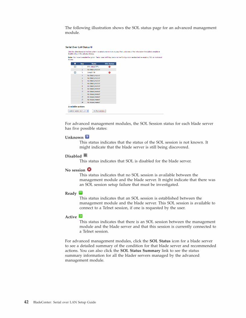
The following illustration shows the SOL status page for an advanced managementmodule.
For advanced management modules, the SOL Session status for each blade serverhas five possible states:
UnknownThis status indicates that the status of the SOL session is not known. Itmight indicate that the blade server is still being discovered.
DisabledThis status indicates that SOL is disabled for the blade server.
No sessionThis status indicates that no SOL session is available between themanagement module and the blade server. It might indicate that there wasan SOL session setup failure that must be investigated.
ReadyThis status indicates that an SOL session is established between themanagement module and the blade server. This SOL session is available toconnect to a Telnet session, if one is requested by the user.
ActiveThis status indicates that there is an SOL session between the managementmodule and the blade server and that this session is currently connected toa Telnet session.
For advanced management modules, click the SOL Status icon for a blade serverto see a detailed summary of the condition for that blade server and recommendedactions. You can also click the SOL Status Summary link to see the statussummary information for all the blader servers managed by the advancedmanagement module.
42 BladeCenter: Serial over LAN Setup Guide

If an SOL session closes itself, or if the session indicates that it is active and is notresponding, complete the following steps:1. Disable SOL for the affected blade server (see “Enabling SOL for blade servers”
on page 12).2. Wait 60 seconds.3. Re-enable SOL for the blade server (see “Enabling SOL for blade servers” on
page 12).
Problems with SOL sessions can also be due to incorrect BladeCenter configuration,or installation of components or firmware that are not SOL compatible.
Restarting a blade server through SOLYou can restart a blade server during an SOL session by typing a specific keysequence. This makes it possible to restart the blade server without ending the SOLsession so that you can use the restart command in the management-modulecommand-line interface.
Type the following key sequence (Esc R Esc r Esc R) to restart a blade serverduring an SOL session:1. Press Esc.2. Type a capital R by pressing Shift and r at the same time.3. Press Esc.4. Press r.5. Press Esc.6. Type a capital R by pressing Shift and r at the same time.
The blade server that is hosting this SOL session restarts, returning to the SOLsession that is already in progress.
Note: The keys pressed to restart a blade server can be set to another user-definedkeystroke sequence. See the BladeCenter Management Module User’s Guide forinformation.
Chapter 5. Using SOL 43

Mounting and unmounting media for Linux operating systemsThe following sections describe how to mount and unmount media using theLinux operating system for each blade server type.
For BladeCenter units that do not have a diskette drive, you can mount onlyoptical drive media.
Mounting and unmounting media using LinuxThe following section describes how to mount and unmount media using aLinuxoperating system.
Note: These procedures are based on a default installation of Red Hat EnterpriseLinux ES 2.1. The file names, structures, and commands might be different forother versions of Red Hat Linux or other types of Linux operating systems.
Complete the following steps if the medium to be mounted is a CD:1. Make sure that the /mnt/cdrom directory exists on your server. If this
directory does not exist, type mkdir /mnt/cdrom and then press Enter.2. To mount the CD, type mount /dev/scd0 –t iso9660 –o ro /mnt/cdrom and
then press Enter.
Complete the following steps if the medium to be mounted is a diskette:1. Make sure that the /mnt/floppy directory exists on your server. If this
directory does not exist, typemkdir /mnt/floppy
and then press Enter.2. To mount the diskette, type
mount /dev/sda –o auto /mnt/floppy
and then press Enter.
Complete the following steps to unmount media:1. Type cd and then press Enter.2. Type one of the following commands:
v If the medium to be unmounted is a CD, typeumount /mnt/cdrom
and then press Enter.v If the medium to be unmounted is a diskette, type
umount /mnt/floppy
and then press Enter.
44 BladeCenter: Serial over LAN Setup Guide
Chapter 6. Troubleshooting SOL
This section contains some troubleshooting hints and tips to assist you in solvingproblems that you might be experiencing with Serial over LAN operation. Go tohttp://www.ibm.com/systems/support/ for the latest information about solvingproblems with SOL. Information in this section relates to the following topics:
Note: If you are using management channel auto discovery (MCAD), replacereferences to I/O-module bay 1 in the following procedures with the I/O modulebay number that is actually being used (see the BladeCenter Advanced ManagementModule User's Guide for additional information about MCAD).v “Management module indicates that blade server does not support SOL”v “Blade server shows SOL status of Not Ready” on page 46v “SOL session opens and drops” on page 47v “Trouble entering SOL commands or receiving double prompts” on page 48v “Garbage characters in an SOL session” on page 48
Management module indicates that blade server does not support SOLIf the management module SOL configuration page indicates that a blade serverdoes not support SOL, check the following items:v Make sure that blade server type that you are using supports SOL. For example,
the Type 8678 blade server does not support SOL and this is a normal messagefor this blade server type.
v The management module has not completed its communication sequence witheach of the blade servers in the BladeCenter unit. This condition commonlyoccurs immediately after power has been applied to the BladeCenter unit orafter an management module reset. Allow 5 minutes after power application or amanagement module reset to make sure that all blade servers have beenscanned.
v Turn off the blade server, remove it from the BladeCenter unit, reinstall it, andturn it back on.
v Move the blade server to a different blade bay.v Update the blade server service processor firmware (BMC or ISMP firmware).
Latest firmware is available from http://www.ibm.com/systems/support/.Install the update by following the instructions that come with the update. Seethe Management Module User's Guide for additional information.
v Try a different management module. If the BladeCenter unit contains a standbymanagement module, switch control to it and wait 5 minutes for themanagement module to fully establish communications with all blade servers.
v Update the management module firmware. Latest firmware is available fromhttp://www.ibm.com/systems/support/. Install the update by following theinstructions that come with the update. See the Management Module User's Guidefor additional information.
v There might be a problem with the blade server system board.
© Copyright IBM Corp. 2009 45

Blade server shows SOL status of Not ReadyIf a blade server with SOL enabled in the management module indicates an SOLstatus of Not Ready, check the following items:v Make sure that an Ethernet switch module is installed in I/O-module bay 1. An
Ethernet switch module needs to be installed in I/O module bay 1; pass-thrumodules do not support SOL.
v Make sure that the SOL port assignment is set to blade server NIC 1, the defaultSOL port assignment that connects to the switch module in bay 1. The Type 8832blade server provides a jumper to change the SOL port assignment. All bladeservers except the HS40 and JS2x blade servers provide a setting in the networkcontroller firmware to change the SOL port assignment. This setting can bechanged only when flashing the NIC firmware on the blade server. If SOL traffichas been assigned to NIC 2, then the switch module in I/O-module bay 2 needsto be an Ethernet switch module and additional configuration of this switchmodule might be required. See Chapter 2, “General configuration,” on page 7,Chapter 3, “Operating system configuration,” on page 15, and Chapter 4,“Special component requirements,” on page 25 for more information.
v Make sure that SOL is properly set up in the blade server system firmware(BIOS). Only the JS2x family of blade servers do not require system firmwareconfiguration to enable SOL. See “Updating and configuring the blade serverBIOS” on page 13 and Chapter 4, “Special component requirements,” on page 25,for information about setting up blade server BIOS for SOL operation.
Note: A blade server might start slowly or become unresponsive if COM 1 isconfigured for SOL instead of COM 2.
v Make sure that the SOL IP address range (for the BSMP) is not already in use onthe external network. The default SOL BSMP address range starts at 10.1.1.80and ends at 10.1.1.93 for all 14 blades in the BladeCenter unit. If any bladeservers or other external devices use this range of IP addresses for productiontraffic, an IP address conflict will occur and SOL traffic might be blocked. TheSOL BSMP starting address can be changed using the management module Webinterface and any IP address range can be used that is not being used forproduction traffic.
v If the blade server has an operating system loaded, verify that the BroadcomNIC drivers are loaded and up to date. A downlevel NIC driver loaded in Linuxcan cause SOL to go into the Not Ready state.
v Make sure that the blade server is powered up. Some blade servers need to bepowered up for SOL to indicate a status of Ready. It can take up to 60 secondsafter some blade servers are powered up for SOL to indicate that they are Ready.
v Make sure that the management module can communicate with the switchmodule in I/O-module bay 1. Verify communications by pinging the I/Omodule from the management module. See the Management Module User's Guidefor additional information.
v Make sure that the Ethernet switch module in I/O-module bay 1 is configuredfor SOL operation. For most switch modules, the default configuration settingsfor the management module and the switch module are fine; however, if theswitch module in I/O-module bay 1 is a Cisco Systems Intelligent GigabitEthernet Switch Module for the IBM BladeCenter, make sure that it has afirmware level of 12.1(22)EA6a or later. (This is the minimum firmware level thatthe switch module requires to support a management module default SOLVLAN of 4095.) If the Cisco Gigabit Ethernet Switch Module has a firmwarelevel older than 12.1(22)EA6a, then the SOL VLAN must be set to a valuebetween 1 and 1001 and the Cisco switch needs to be configured for these
46 BladeCenter: Serial over LAN Setup Guide
setting (see “Configuring the Cisco Systems Intelligent Gigabit Ethernet SwitchModule for the IBM BladeCenter” on page 34). If the BladeCenter I/O moduleinternal ports are VLAN enabled (‘trunked’ in Cisco terms), then these portsmust be configured to pass traffic from the SOL VLAN ID.
v Restart the blade server system management processor (see the ManagementModule User's Guide or the Management Module Command-line Interface ReferenceGuide for instructions). Make sure that the blade server is turned on whenrestarting the management processor. After the restart is complete, check theblade server SOL status; if the status indicates Ready, then try to start an SOLsession.
v Disable SOL for the blade server; then, re-enable it (see the Management ModuleUser's Guide or the Management Module Command-line Interface Reference Guide forinstructions). Make sure that the blade server is turned on when disabling andre-enabling SOL. After the disable and re-enable is complete, check the bladeserver SOL status; if the status indicates Ready, then try to start an SOL session.
v Restart the management module (see the Management Module User's Guide or theManagement Module Command-line Interface Reference Guide for instructions). Afterthe restart is complete, check the blade server SOL status; if the status indicatesReady, then try to start an SOL session.
v Restart the switch module in I/O-module bay 1 (see the Management ModuleUser's Guide or the Management Module Command-line Interface Reference Guide forinstructions). After the restart is complete, check the blade server SOL status; ifthe status indicates Ready, then try to start an SOL session.
v Turn off the blade server, remove it from the BladeCenter unit, reinstall it, andturn it back on. After doing this, check the blade server SOL status; if the statusindicates Ready, then try to start an SOL session.
SOL session opens and dropsIf you can open an SOL session with a blade server but it will not remain open,check the following items:v Make sure that the session timeout has not expired. The management module
has a default timeout value of 120 seconds for command-line interface sessions.This value can be changed to never timeout using the command: telnetcfg –Tsystem:mm[x] –t 0 (where x is the primary management-module bay number).See the Management Module Command-line Interface Reference Guide forinstructions.
v (For HS20 Type 8832, JS20 Type 8842, HS20 Type 8843, and LS20 Type 8850 bladeservers only) SOL traffic shares blade server NIC port 1 with regular Ethernettraffic. Do not try to use SOL on a blade server while attempting to PXE boot itthrough NIC port 1. Traffic from a network install server running through bladeserver port 1 can block SOL traffic, which will cause the SOL session to hang.
v Make sure that the latest Broadcom Ethernet driver is installed on the bladeserver, especially for blade servers running a Linux operating system.
v Do not type on the keyboard while the blade server is rebooting or the operatingsystem network drivers are loading; this action has been known to cause an SOLsession to drop.
Chapter 6. Troubleshooting SOL 47
Trouble entering SOL commands or receiving double promptsIf you are having trouble entering commands in an SOL session or are receivingdouble prompts, check the following items:v Check the keyboard Return key settings for your terminal emulation program.
Make sure that only a line-feed character is sent whenever the Return key ispressed (Telnet works this way by default). The Putty terminal application has aconfiguration setting for the Return key under Configuration → Connection →Telnet.
v The service processor on older blade servers, including the Type 8832 and Type8842 blade servers, might block SOL output to a blade server that is runningLinux. If this happens, enter Ctrl+q in the SOL session to clear the keystrokebuffer.
v Make sure that the operating system that is running on the blade serversupports SOL. See Chapter 3, “Operating system configuration,” on page 15 forinstructions.
v Make sure that the operating system that is running on the blade server is set upcorrectly for SOL console access (see Chapter 3, “Operating systemconfiguration,” on page 15 for instructions). For example, you must enable theWindows Emergency Management System (EMS) for Windows Server 2003 andredirect it to the COM2 serial port.
Garbage characters in an SOL sessionThe default character encoding in Linux does not translate many of the characterssent over an SOL session, which might corrupt the BIOS screens display. If you aregetting garbage characters while viewing or typing in an SOL session, check thefollowing items:v Make sure the serial port settings in your terminal emulation program match the
settings specified in the blade server BIOS configuration. Also, make sure thatHardware Flow Control is enabled.
v Try setting the remote console text and keyboard emulation to VT100/220,instead of ANSI, in blade server BIOS. This might improve character display inSOL sessions. These setting are found in the blade server BIOS, under Devicesand I/O Ports → Remote Console Redirection.
v To correct garbage or missing characters when using Gnome Terminal on aremote computer, complete the following steps:1. From the Gnome Terminal menu, select Terminal → Set Character Encoding
→ Add or Remove.2. From the list of available encodings that displays, select Western IBM850;
then, click on the right-arrow button to add this encoding to the list ofencodings shown in the menu and click OK.
3. From the Gnome Terminal menu, select Terminal → Set Character Encoding →Western (IBM850).
Using these settings for the Gnome Terminal should greatly reduce the amountof garbage or missing characters.
v Try a different terminal emulation program. Several programs are available, suchas Telnet, Putty, or Hyperterm.
v Update the blade server service processor firmware (BMC or ISMP firmware).Latest firmware is available from http://www.ibm.com/systems/support/.Install the update by following the instructions that come with the update. Seethe Management Module User's Guide for additional information.
48 BladeCenter: Serial over LAN Setup Guide

v Restart blade server system management processor (see the Management ModuleUser's Guide or the Management Module Command-line Interface Reference Guide forinstructions).
v Check the external link statistics for the switch module in I/O-module bay 1.Look for high packet loss or high packet error rates. See the Management ModuleUser's Guide for additional information.
v Try to start an SOL session with another blade server in the BladeCenter unit. Ifyou see garbage or missing characters with all blade server sessions, thensuspect the management module.
v If the blade server supports local KVM, then switch the local command consoleto the blade server and type some characters. If you see the same garbage ormissing character problem, then the problem is most likely with themanagement module.
Chapter 6. Troubleshooting SOL 49

50 BladeCenter: Serial over LAN Setup Guide

Appendix A. Getting help and technical assistance
If you need help, service, or technical assistance or just want more informationabout IBM products, you will find a wide variety of sources available from IBM toassist you. This section contains information about where to go for additionalinformation about IBM and IBM products, what to do if you experience a problemwith your system, and whom to call for service, if it is necessary.
Before you callBefore you call, make sure that you have taken these steps to try to solve theproblem yourself:v Check all cables to make sure that they are connected.v Check the power switches to make sure that the system and any optional
devices are turned on.v Use the troubleshooting information in your system documentation, and use the
diagnostic tools that come with your system. Information about diagnostic toolsis in the Problem Determination and Service Guide on the IBM Documentation CDthat comes with your system.
v Go to the IBM support Web site at http://www.ibm.com/systems/support/ tocheck for technical information, hints, tips, and new device drivers or to submita request for information.
You can solve many problems without outside assistance by following thetroubleshooting procedures that IBM provides in the online help or in thedocumentation that is provided with your IBM product. The documentation thatcomes with IBM systems also describes the diagnostic tests that you can perform.Most systems, operating systems, and programs come with documentation thatcontains troubleshooting procedures and explanations of error messages and errorcodes. If you suspect a software problem, see the documentation for the operatingsystem or program.
Using the documentationInformation about your IBM system and preinstalled software, if any, or optionaldevice is available in the documentation that comes with the product. Thatdocumentation can include printed documents, online documents, readme files,and help files. See the troubleshooting information in your system documentationfor instructions for using the diagnostic programs. The troubleshooting informationor the diagnostic programs might tell you that you need additional or updateddevice drivers or other software. IBM maintains pages on the World Wide Webwhere you can get the latest technical information and download device driversand updates. To access these pages, go to http://www.ibm.com/systems/support/and follow the instructions. Also, some documents are available through the IBMPublications Center at http://www.ibm.com/shop/publications/order/.
© Copyright IBM Corp. 2009 51

Getting help and information from the World Wide WebOn the World Wide Web, the IBM Web site has up-to-date information about IBMsystems, optional devices, services, and support. The address for IBM System xand xSeries information is http://www.ibm.com/systems/x/. The address for IBMBladeCenter information is http://www.ibm.com/systems/bladecenter/. Theaddress for IBM IntelliStation® information is http://www.ibm.com/intellistation/.
You can find service information for IBM systems and optional devices athttp://www.ibm.com/systems/support/.
Software service and supportThrough IBM Support Line, you can get telephone assistance, for a fee, with usage,configuration, and software problems with System x and xSeries servers,BladeCenter products, IntelliStation workstations, and appliances. For informationabout which products are supported by Support Line in your country or region,see http://www.ibm.com/services/sl/products/.
For more information about Support Line and other IBM services, seehttp://www.ibm.com/services/, or see http://www.ibm.com/planetwide/ forsupport telephone numbers. In the U.S. and Canada, call 1-800-IBM-SERV(1-800-426-7378).
Hardware service and supportYou can receive hardware service through your IBM reseller or IBM Services. Tolocate a reseller authorized by IBM to provide warranty service, go tohttp://www.ibm.com/partnerworld/ and click Find a Business Partner on theright side of the page. For IBM support telephone numbers, seehttp://www.ibm.com/planetwide/. In the U.S. and Canada, call 1-800-IBM-SERV(1-800-426-7378).
In the U.S. and Canada, hardware service and support is available 24 hours a day,7 days a week. In the U.K., these services are available Monday through Friday,from 9 a.m. to 6 p.m.
IBM Taiwan product service
IBM Taiwan product service contact information:IBM Taiwan Corporation3F, No 7, Song Ren Rd.Taipei, TaiwanTelephone: 0800-016-888
52 BladeCenter: Serial over LAN Setup Guide

Appendix B. Notices
TrademarksIBM, the IBM logo, and ibm.com® are trademarks or registered trademarks ofInternational Business Machines Corporation in the United States, other countries,or both. If these and other IBM trademarked terms are marked on their firstoccurrence in this information with a trademark symbol (® or ™), these symbolsindicate U.S. registered or common law trademarks owned by IBM at the time thisinformation was published. Such trademarks may also be registered or commonlaw trademarks in other countries. A current list of IBM trademarks is available onthe Web at “Copyright and trademark information”at http://www.ibm.com/legal/copytrade.shtml.
Adobe and PostScript are either registered trademarks or trademarks of AdobeSystems Incorporated in the United States and/or other countries.
Cell Broadband Engine is a trademark of Sony Computer Entertainment, Inc., inthe United States, other countries, or both and is used under license therefrom.
Intel, Intel Xeon, Itanium, and Pentium are trademarks or registered trademarks ofIntel Corporation or its subsidiaries in the United States and other countries.
Java™ and all Java-based trademarks are trademarks of Sun Microsystems, Inc., inthe United States, other countries, or both.
Linux is a registered trademark of Linus Torvalds in the United States, othercountries, or both.
Microsoft, Windows, and Windows NT are trademarks of Microsoft Corporation inthe United States, other countries, or both.
UNIX is a registered trademark of The Open Group in the United States and othercountries.
Other company, product, or service names may be trademarks or service marks ofothers.
Important notesProcessor speeds indicate the internal clock speed of the microprocessor; otherfactors also affect application performance.
CD or DVD drive speed is the variable read rate. Actual speeds vary and are oftenless than the possible maximum.
When referring to processor storage, real and virtual storage, or channel volume,KB stands for 1024 bytes, MB stands for 1 048 576 bytes, and GB stands for1 073 741 824 bytes.
When referring to hard disk drive capacity or communications volume, MB standsfor 1 000 000 bytes, and GB stands for 1 000 000 000 bytes. Total user-accessiblecapacity can vary depending on operating environments.
© Copyright IBM Corp. 2009 53

Maximum internal hard disk drive capacities assume the replacement of anystandard hard disk drives and population of all hard disk drive bays with thelargest currently supported drives available from IBM.
Maximum memory might require replacement of the standard memory with anoptional memory module.
IBM makes no representation or warranties regarding non-IBM products andservices that are ServerProven, including but not limited to the implied warrantiesof merchantability and fitness for a particular purpose. These products are offeredand warranted solely by third parties.
IBM makes no representations or warranties with respect to non-IBM products.Support (if any) for the non-IBM products is provided by the third party, not IBM.
Some software might differ from its retail version (if available), and might notinclude user manuals or all program functionality.
54 BladeCenter: Serial over LAN Setup Guide

Index
Aassistance, getting 51
Bblade server
enable SOL 12Linux Ethernet driver 21remote console redirection
settings 13restart through SOL 43SOL status 12update firmware (BIOS) 13
blade server HS20 Type 8832configure 27firmware update (Ethernet
controller) 29firmware update (ISMP) 28jumper position 28Linux configuration 15
blade server HS20 Type 8843configure 27firmware update (Ethernet
controller) 29firmware update (ISMP) 28Linux configuration 15
blade server HS22 Type 7870configure 25
blade server HS40 Type 8839configure 29firmware update (BMC) 29Linux configuration 15remote console redirection
settings 30update firmware (BIOS) 30
blade server JS20 Type 8842configure 31firmware update (Ethernet
controller) 32firmware update (ISMP) 31update firmware (BIOS) 31
Cchecking firmware 4Cisco Systems Intelligent Gigabit Ethernet
Switch Module configuration 34command-line interface
starting 37configuration
special requirements 25configure
blade server HS20 Type 8832 27blade server HS20 Type 8843 27blade server HS22 Type 7870 25blade server HS40 Type 8839 29blade server JS20 Type 8842 31Cisco Systems Intelligent Gigabit
Ethernet Switch Module 34global SOL settings 7, 40
configure (continued)GRUB 17IBM 4-port Gb Ethernet I/O 32LILO 16Linux (HS20 Type 8832 blade
server) 15Linux (HS20 Type 8843 blade
server) 15Linux (HS40 Type 8839 blade
server) 15management module 9Microsoft Windows 2003 22Nortel Layer 2-7 GbE I/O 33Red Hat Enterprise Linux 15SSH 11SUSE Linux 19
connectICPM 35Intelligent Copper Pass-thru
Module 35
Ddevice driver
blade server (Linux for Ethernetcontroller) 21
documentation, latest version 2
EEmergency Management System (EMS)
Microsoft Windows 2003 22enable SOL for blade server 12ending an SOL session 40
Ffirmware
checking version 4firmware requirements 3firmware update
blade server (BIOS) 13blade server HS20 Type 8832 (Ethernet
controller) 29blade server HS20 Type 8832
(ISMP) 28blade server HS20 Type 8843 (Ethernet
controller) 29blade server HS20 Type 8843
(ISMP) 28blade server HS40 Type 8839
(BIOS) 30blade server HS40 Type 8839
(BMC) 29blade server JS20 Type 8842
(BIOS) 31blade server JS20 Type 8842 (Ethernet
controller) 32blade server JS20 Type 8842
(ISMP) 31
firmware update (continued)management module 10
firmware versions 3
Ggetting help 51global SOL settings, configure 7, 40GRUB configuration 17
Hhardware flow control 15, 19hardware requirements 2hardware service and support
IBM reseller 52IBM Services 52telephone numbers 52
help, getting 51
IIBM 4-port Gb Ethernet I/O
configuration 32IBM Support Line 52ICPM connection 35install, SSH 11Intelligent Copper Pass-thru Module
connection 35
Jjumper position
blade server HS20 Type 8832 28
LLILO configuration 16Linux
mounting media 44unmounting media 44
Linux configurationHS20 Type 8832 blade server 15HS20 Type 8843 blade server 15HS40 Type 8839 blade server 15
Linux driverblade server Ethernet controller 21
Mmanagement module
configuration 9configure SOL 10enable SOL 11firmware update 10
management-module firmware 3management-module Web interface
starting 5
© Copyright IBM Corp. 2009 55

maximum numberSOL sessions 1, 2, 37Telnet sessions 1, 37
mediamount (Linux) 44unmount (Linux) 44
Microsoft Windows 2003configuration 22Emergency Management System
(EMS) 22mount media, Linux 44
NNortel Layer 2-7 GbE I/O
configuration 33notes, important 53
Oonline documentation 2
RRed Hat Enterprise Linux
configuration 15remote console redirection
blade server 13blade server HS40 Type 8839 30
requiredfirmware 3hardware 2
Sserial
connection 38Serial over LAN 1, 40software service and support 52SOL 1, 40
blade server restart 43configure management module 10enable blade server 12enable for management module 11starting
from command line 39status of blade server 12troubleshooting 45using 37
SOL sessionending 40maximum allowed 1, 2, 37starting 37, 40
SOL settings, configure global 7, 40SSH
connection 39install and configure 11
startingcommand-line interface 37management-module Web interface 5session using serial 38session using SSH 39session using Telnet 38SOL from command line 39SOL session 37, 40
status, SOL for blade server 12support, web site 51SUSE Linux configuration 19
Ttelephone numbers
hardware service and support 52Telnet connection 38Telnet sessions, maximum allowed 1, 37trademarks 53troubleshooting
double prompts in SOL session 48garbage characters in SOL session 48missing characters in SOL session 48no SOL support 45SOL not ready 46SOL sessions drop 47trouble entering SOL commands 48
troubleshooting SOL 45
Uunmount media, Linux 44using SOL 37
Wweb site
publication ordering 51support 51support line, telephone numbers 52
56 BladeCenter: Serial over LAN Setup Guide


����
Part Number: 44R5390
Printed in USA
(1P) P/N: 44R5390


