BladeCenter S Type 7779/8886: Installation and...
80
IBM BladeCenter S Type 7779/8886 Installation and User's Guide
Transcript of BladeCenter S Type 7779/8886: Installation and...

IBM BladeCenter SType 7779/8886
Installation and User's Guide
���


IBM BladeCenter SType 7779/8886
Installation and User's Guide
���

NoteNote: Before using this information and the product it supports, read the general information inNotices; and read the IBM Safety Information and the IBM Systems Environmental Notices and UserGuide on the IBM Documentation CD.
Eighth Edition (July 2013)
© Copyright IBM Corporation 2007, 2013.US Government Users Restricted Rights – Use, duplication or disclosure restricted by GSA ADP Schedule Contractwith IBM Corp.

Contents
Chapter 1. Introduction . . . . . . . . 1Related documentation . . . . . . . . . . . 2The IBM BladeCenter Documentation CD. . . . . 3Notices and statements in this document . . . . . 4Features and specifications. . . . . . . . . . 5Components of the BladeCenter S system. . . . . 6
Front view of the BladeCenter S chassis . . . . 6Rear view of the BladeCenter S chassis . . . . 14
Systems and storage management . . . . . . . 24IBM Director . . . . . . . . . . . . . 24Storage Configuration Manager. . . . . . . 24
Chapter 2. Installing the BladeCenter STypes 7779 and 8886. . . . . . . . . 27Installation guidelines . . . . . . . . . . . 27
System reliability guidelines . . . . . . . . 28Handling static-sensitive devices . . . . . . 28
Preparing to install your BladeCenter S system . . 29Verifying ship group contents . . . . . . . 29Obtaining firmware and device drivers . . . . 29Obtaining configuration, systems management,and storage management software. . . . . . 30
Setting up your BladeCenter S system . . . . . 30Removing components . . . . . . . . . 30Installing the BladeCenter S chassis in a rack . . 34Installing components . . . . . . . . . . 39Cabling the BladeCenter S chassis . . . . . . 46Connecting the BladeCenter S chassis to power 47Disconnecting power from the BladeCenter unit 47
Chapter 3. Installing IBM DirectorServer (optional) . . . . . . . . . . 49
Chapter 4. Configuring the BladeCenterS system . . . . . . . . . . . . . . 51Configuring I/O modules . . . . . . . . . 51Configuring blade servers . . . . . . . . . 52Selecting shared BladeCenter resources . . . . . 53
Appendix A. Getting help and technicalassistance . . . . . . . . . . . . . 55Before you call . . . . . . . . . . . . . 55Using the documentation . . . . . . . . . . 56
Getting help and information from the World WideWeb . . . . . . . . . . . . . . . . . 56How to send DSA data to IBM . . . . . . . . 56Creating a personalized support web page . . . . 57Software service and support . . . . . . . . 57Hardware service and support . . . . . . . . 57IBM Taiwan product service . . . . . . . . . 58
Appendix B. Parts listing . . . . . . . 59Front view parts listing . . . . . . . . . . 59Rear view parts listing. . . . . . . . . . . 60
Notices . . . . . . . . . . . . . . 63Trademarks . . . . . . . . . . . . . . 64Important notes . . . . . . . . . . . . . 64Particulate contamination. . . . . . . . . . 65Documentation format. . . . . . . . . . . 66Telecommunication regulatory statement . . . . 66Electronic emission notices . . . . . . . . . 66
Federal Communications Commission (FCC)statement . . . . . . . . . . . . . . 67Industry Canada Class A emission compliancestatement . . . . . . . . . . . . . . 67Avis de conformité à la réglementationd'Industrie Canada . . . . . . . . . . . 67Australia and New Zealand Class A statement . 67European Union EMC Directive conformancestatement . . . . . . . . . . . . . . 67Germany Class A statement . . . . . . . . 68Japan VCCI Class A statement . . . . . . . 69Japan Electronics and Information TechnologyIndustries Association (JEITA) statement. . . . 69Japan Electronics and Information TechnologyIndustries Association (JEITA) statement. . . . 69Korea Communications Commission (KCC)statement . . . . . . . . . . . . . . 69Russia Electromagnetic Interference (EMI) ClassA statement . . . . . . . . . . . . . 70People's Republic of China Class A electronicemission statement . . . . . . . . . . . 70Taiwan Class A compliance statement . . . . 70
Index . . . . . . . . . . . . . . . 71
© Copyright IBM Corp. 2007, 2013 iii

iv BladeCenter S Type 7779/8886: Installation and User's Guide

Chapter 1. Introduction
The BladeCenter S Type 8886 is a high-density, high-performance rack-mountedserver system. It supports up to six blade servers that can share common resources,such as power, cooling, management, and I/O resources within a singleBladeCenter S chassis. In addition, it provides support for up to twelve 3.5-inch,hot-swappable SAS or SATA hard disk drives or twenty-four 2.5-inch,hot-swappable SAS hard disk drives.
The BladeCenter S system provides the following features:v IBM® Enterprise X-Architecture Technology
IBM Enterprise X-Architecture Technology leverages proven innovative IBMtechnologies to build powerful, scalable, and reliable blade servers. It providesfeatures such as IBM Predictive Failure Analysis (PFA) and real-time diagnostics.
v Server expansion capabilities
You can add up to six blade servers to the BladeCenter S chassis. Some bladeservers have connectors for additional optional devices that you can use to addcapabilities to the blade server. For example, you can connect either a storageexpansion unit or a PCI expansion unit to a blade server. Alternatively, you canadd optional I/O expansion cards to add network interfaces or storage throughI/O modules. SAS expansion cards provide access through SAS connectivitymodules or SAS RAID controller modules that are installed in I/O bays 3 and 4to the hard disk drives in the BladeCenter S chassis.
Note: SAS connectivity modules support the use of SAS or SATA hard diskdrives. SAS RAID controller modules support the use of SAS hard disk drivesonly.
v Hot-swap capabilities
Bays in the BladeCenter S chassis are hot-swappable. For example, you can add,remove, or replace a blade server or a SAS or SATA hard disk drive withoutremoving power from the BladeCenter S chassis.The midplane provides hot-pluggable connectors for the following components:– Six blade servers– Four I/O modules– One advanced management module– One serial pass-thru module– Four power modules– Four fan modules– Two disk storage modules– One media tray
v High-availability design
Components in the BladeCenter S system enable continued operation if one ofthe components fails:– Power modules. In normal operation, the power modules provide power to
share the system load. If a power module fails, the working power modulescan continue to handle the entire load. You can replace a power modulewithout shutting down the BladeCenter S system.
© Copyright IBM Corp. 2007, 2013 1

Note: The power management policy that you have implemented for theBladeCenter S system determines the result of a power module failure.Power modules also provide cooling fans for the disk storage modules.Therefore, if you are using disk storage module 1, you must install powermodules 1 and 2. If you are using disk storage module 2, you must installpower modules 3 and 4.
– Fan modules. In normal operation, fan modules share the cooling in theBladeCenter S system. If one fan module fails, the other three fan moduleshandle the entire load. You can replace a fan module without shutting downthe BladeCenter S system.
– BladeCenter S system midplane. The midplane has the followingcharacteristics:- Redundant high-speed serialize/deserialize (SERDES) interconnects
between blade servers and switches- I2C communication between the advanced management module and all
modules (except blade servers)- RS-485 (EIA 485) communication between the advanced management
module and blade servers- Analog video connectors from the blade servers to the advanced
management module- USB connections between the blade servers and the advanced management
modulev Systems management
The advanced management module is used to communicate with the serviceprocessor in each blade server to provide system monitoring, event recording,and alerts. You can manage the BladeCenter S chassis, its devices, and the bladeservers remotely.
Related documentationIn addition to this document, the following related documentation is provided inPortable Document Format (PDF) on the IBM BladeCenter Documentation CD thatcomes with your BladeCenter S chassis.
Note: The latest and most up-to-date product information for the BladeCenter STypes 7779 and 8886 can be found at the IBM Systems Information Center, whichis at http://publib.boulder.ibm.com/infocenter/systems/index.jsp. To access theBladeCenter S system documentation from this site, click Systems hardware >BladeCenter information > Chassis > BladeCenter S (8886).
In addition to the product documentation, online education is also available at thislocation.v BladeCenter S Types 7779 and 8886 Planning Guide
This document contains information to plan for the physical installation andconfiguration of the BladeCenter S Types 7779 and 8886.
v BladeCenter S Types 7779 and 8886 Problem Determination and Service Guide
This document contains information for troubleshooting your BladeCenter Ssystem and solving problems.
v Serial over LAN Setup Guide
This guide provides detailed Serial over LAN configuration information for yourBladeCenter S system.
2 BladeCenter S Type 7779/8886: Installation and User's Guide
v Safety Information
This document contains translated caution and danger statements. Each cautionand danger statement in the documentation has a number that you can use tolocate the corresponding statement in your language in the Safety Informationdocument.
v Warranty and Support
This document contains information about the terms of the warranty and gettingservice and assistance.
Additional documentation might be included on the IBM BladeCenter DocumentationCD.
The BladeCenter S chassis might have features that are not described in thedocumentation that comes with the BladeCenter S chassis. The documentationmight be updated occasionally to include information about those features, ortechnical updates might be available to provide additional information that is notincluded in the BladeCenter documentation. These updates are available from theIBM Web site. To check for updated documentation, go to http://publib.boulder.ibm.com/infocenter/bladectr/documentation/index.jsp.
The IBM BladeCenter Documentation CDThe IBM BladeCenter Documentation CD contains documentation for yourBladeCenter S chassis in Portable Document Format (PDF) and includes the IBMDocumentation Browser to help you find information quickly.
Hardware and software requirements
The IBM BladeCenter Documentation CD requires the following minimum hardwareand software:v Microsoft Windows NT XP, Windows 2000, or Red Hat Linuxv 100 MHz microprocessorv 32 MB RAMv Adobe Acrobat Reader 3.0 (or later) or xpdf, which comes with Linux operating
systems
Using the Documentation CD
Use the Documentation Browser to browse the contents of the CD, read briefdescriptions of the documents, and view documents, using Adobe Acrobat Readeror xpdf. The Documentation Browser automatically detects the regional settings inuse in your system and presents the information in the language for that region (ifavailable). If a topic is not available in the language for that region, theEnglish-language version is displayed.
Use one of the following procedures to start the Documentation Browser:v If Autostart is enabled, insert the CD into the DVD drive. The Documentation
Browser starts automatically.v If Autostart is disabled or is not enabled for all users:
– If you are using a Windows operating system, insert the CD into the DVDdrive, and click Start > Run. In the Open field, type:e:\win32.bat
where e is the drive letter of your DVD drive, and click OK.
Chapter 1. Introduction 3

– If you are using a Red Hat Linux, insert the CD into the DVD drive; then, runthe following command from the /mnt/cdrom directory:sh runlinux.sh
Select your BladeCenter S chassis from the Product menu. The Available Topicslist displays all the documents for your BladeCenter product. Some documentsmight be in folders. A plus sign (+) indicates each folder or document that hasadditional topics under it. Click the plus sign to display the additional documents.
When you select a document, a description of the document appears under TopicDescription. To select more than one document, press and hold the Ctrl key whileyou select the documents. Click View Book to view the selected document ordocuments in Acrobat Reader or xpdf. If you selected more than one document, allthe selected documents are opened in Acrobat Reader or xpdf.
To search all the documents, type a word or word string in the Search field andclick Search. The documents in which the word or word string appears are listedin order of the most occurrences. Click a document to view it, and press Ctrl+F touse the Acrobat search function, or press Alt+F to use the xpdf search functionwithin the document.
Click Help for detailed information about using the Documentation Browser.
Notices and statements in this documentThe caution and danger statements in this document are also in the multilingualSafety Information document, which is on the IBM BladeCenter Documentation CD.Each statement is numbered for reference to the corresponding statement in yourlanguage in the Safety Information document.
The following notices and statements are used in this document:v Note: These notices provide important tips, guidance, or advice.v Important: These notices provide information or advice that might help you
avoid inconvenient or problem situations.v Attention: These notices indicate potential damage to programs, devices, or data.
An attention notice is placed just before the instruction or situation in whichdamage might occur.
v Caution: These statements indicate situations that can be potentially hazardousto you. A caution statement is placed just before the description of a potentiallyhazardous procedure step or situation.
v Danger: These statements indicate situations that can be potentially lethal orextremely hazardous to you. A danger statement is placed just before thedescription of a potentially lethal or extremely hazardous procedure step orsituation.
4 BladeCenter S Type 7779/8886: Installation and User's Guide

Features and specificationsThe following table provides a summary of the features and specifications of theBladeCenter S chassis.
Media tray (on front):
v One DVD drive (can be either aCD-RW/DVD-ROM orDVD/RW drive)
v Two USB v2.0 ports
v Front system LED panel
v Two battery backup unit baylocations, which support the SASRAID controller modules
Blade bays (on front): Sixhot-swap blade server bays
Disk storage module bays (onfront): Two storage bays, eachcontaining up to six 3.5-inch diskdrive bays or twelve 2.5-inch diskdrive bays.
Module bays (on rear):
v One hot-swap advancedmanagement module bay
v Four hot-swap power modulebays
v Four hot-swap fan module bays
v Four hot-swap I/O module bays
v One hot-swap serial pass-thrumodule bay
Power modules:
v Minimum: Two hot-swap powermodules.
v Maximum: Four hot-swap powermodules
Cooling:
Four variable-speed, hot-swap fanmodules
Two fans in each power supplycool the disk storage modules
Management module:
v One hot-swap advancedmanagement module
Upgradeable microcode:
v Advanced management modulefirmware
v I/O module firmware
v Blade server firmware
v Disk storage module firmware
Security features:
v Login password for remoteconnection
v Secure Sockets Layer (SSL) securityfor remote management access
v Lightweight Directory AccessProtocol (LDAP)
Predictive Failure Analysis (PFA)alerts:
v Fan modules
v Blade-dependent features
Size (7 U):
v Height: 306.3 mm (12 in.)
v Depth: 733.4 mm (28.9 in.)
v Width: 444 mm (17.5 in.)
v Weight:
– Fully configured weight withblade servers: approximately108.86 kg (240 lb)
– Empty chassis without modulesor blade servers: approximately40.82 kg (90 lb)
Environment:
v Air temperature:
– BladeCenter S system on:
- Altitude: 0 to 914 m (3000 ft) 10°to 35°C (50° to 95°F)
- Altitude: 914 m to 2134 m (3000ft to 7000 ft) 10° to 32°C (50° to90°F)
– BladeCenter S system off: -40° to60°C (-40° to 140°F).
v Humidity: 8% to 80%
v Acoustics: declared sound power level:6.3 to 6.8 bels
Electrical input:
v Sine-wave input (50 - 60 Hzsingle-phase) required
v Input voltage (110 V ac):
– Minimum: 100 Vrms
– Maximum: 127 Vrms
v Input voltage (220 V ac):
– Minimum: 200 Vrms
– Maximum: 240 Vrms
Heat output: Approximate heat outputin British thermal units (BTU) per hour:
v Minimum configuration: 1365 Btu perhour (400 watts)
v Maximum configuration: 11942 Btuper hour (3500 watts)
Chapter 1. Introduction 5

Components of the BladeCenter S systemBladeCenter S system components include an advanced management module,blade servers, I/O modules, disk storage modules, power modules, fan modules, aserial pass-thru module, and a media tray.
Front view of the BladeCenter S chassisBlade servers, disk storage modules, and the media tray are installed in the frontof the BladeCenter S chassis.
Note: For proper cooling, each bay in the BladeCenter S chassis must have either adevice or a filler installed.
As the BladeCenter S chassis can support either 3.5-inch disk drives or 2.5-inchdisk drives in the storage bays, the front view of the chassis can appear as either ofthe following.
3.5-inch disk drive configuration:
Storagemodule
1
Storagemodule
2
SAS/SATAhard disk drives
SAS/SATAhard disk drives
Media tray
BladesBattery backupunit 1
Battery backupunit 2
2.5-inch disk drive configuration:
6 BladeCenter S Type 7779/8886: Installation and User's Guide

Disk storage modulesYou can install a maximum of two disk storage modules in the BladeCenter Schassis and each disk storage module contains hot-swap hard disk drives. A diskstorage module and the hard disk drives installed in that disk storage module arecommonly referred to as integrated shared storage because this storage is integratedin the BladeCenter S chassis and shared among the blade servers in theBladeCenter S system.
Each disk storage module can support up to six hot-swap, 3.5-inch or twelvehot-swap, 2.5-inch hard disk drives. For 3.5-inch hard disk drives, if you areinstalling SAS connectivity modules, both SAS and SATA hard disk drives aresupported, and you can use both types of hard disk drives in each disk storagemodule. If you are installing SAS RAID controller modules, you must install SAShard disk drives. For 2.5-inch hard disk drives, please note that only SAS hard diskdrives are supported. Thus, only SAS RAID controllers can be used.
Within each disk storage module, hard disk drives are numbered either 1 through6 from left to right, and top to bottom for the 3.5-inch hard disk driveconfiguration or 1 through 12 for the 2.5-inch hard disk drive configuration.
Note: Each hard disk drive bay must contain either a hard disk drive or adrive-bay filler.
Graphic showing close up of 6-disk disk storage module and indicators
Chapter 1. Introduction 7

Graphic showing close up of 12-disk disk storage module and indicators
Note: Four power modules are required in the BladeCenter S chassis if both diskstorage modules are installed.
To access the hard disk drives in the disk storage module, the following devicesmust be installed:v SAS I/O modules. For the 6-disk storage module, you can choose to install
either SAS connectivity modules or SAS RAID controller modules. As for the12-disk storage module, only the SAS RAID controller module can be installed.
Note: You cannot mix these module types in the same BladeCenter S chassis.– SAS connectivity module. At least one SAS connectivity module must be
installed. If a single SAS connectivity module is installed, it controls access toboth disk storage modules in the BladeCenter S chassis. If two SASconnectivity modules are installed, the module in I/O module bay 3 controlsaccess to disk storage module 1, and the module in I/O module bay 4controls access to disk storage module 2.
– SAS RAID controller module. Two SAS RAID controller modules must beinstalled, one in I/O module bay 3 and the other in I/O module bay 4. EachSAS RAID controller module will have access to both storage modules (forhigh availability).
8 BladeCenter S Type 7779/8886: Installation and User's Guide

v A SAS expansion card in each of the blade servers, which provides accessthrough the SAS I/O modules in I/O module bays 3 and 4 to the SAS or SATAhard disk drives in each disk storage module. This only applies to the 6-diskstorage module.
There is one LED on each disk storage module:
Fault Solid (amber) when there is a disk storage module failure.
There are two LEDs on each hard disk drive:
Green Flashing when an operation, such as a read or a write, is being performed.
AmberFlashing when the hard disk drive is being rebuilt (fast blink) or identified(slow blink).
Note: When power is restored to the BladeCenter S chassis after acomplete loss of power and you have implemented the hard disk drives asa mirrored array, the fault light will blink as the hard disk drive is beingresynchronized.
This resynchronization occurs because the blade servers are attempting topower on before all of the disk storage modules and SAS connectivitymodules or SAS RAID controller module are powered up and available.The mirrored array is accessible during resynchronization althoughperformance may be slightly slower.
Solid when there is a drive failure.
Chapter 1. Introduction 9

Media trayThe media tray contains the DVD drive (which can be either a CD-RW/DVD-ROMdrive or a DVD/RW drive) and two USB v2.0 ports, which are shared by the bladeservers. The media tray also contains two battery backup units, which providebackup for SAS RAID controller modules cache.
Note: The port on the side of the media tray is reserved for future use.
Controls and indicators
Power-on
Location
Over-temperature
Information
System error
The media tray provides the following controls and indicators:
System LED panelThe LEDs on this panel provide status information for the BladeCenter Schassis.
Note: These LEDs are also displayed on the rear of the BladeCenter Schassis.
10 BladeCenter S Type 7779/8886: Installation and User's Guide

Power-onLit (green). Power is being supplied to the BladeCenter S chassis.
Off. The power subsystem, ac power, or the LED has failed.
Note: Even if the power-on LED is off, always remove the powercords from all power modules before you service the BladeCenter Schassis.
LocationLit or flashing (blue). It has been turned on by the systemadministrator to aid in visually locating the BladeCenter S chassis.You can turn off the location LED throught the Web interface orthe IBM Director console.
Over-temperatureLit (amber). The temperature in the BladeCenter S chassis exceedsthe temperature limits, or a blade server reports anover-temperature condition. The BladeCenter S chassis might havealready taken corrective action, such as increasing the fan speed.This LED turns off automatically when there is no longer anover-temperature condition.
InformationLit (amber). A noncritical event has occurred that requiresattention, such as the wrong I/O module being inserted into a bay,or power demands within the BladeCenter S chassis exceeding thecapacity of the installed power modules.
You can turn off the information LED through the Web interface orthe IBM Director console.
System errorLit (amber). A system error has occurred, such as a module failureor a system error in a blade server. An LED on the failingcomponent is also lit to assist in isolating the error.
DVD drive activity LEDLit (green). The drive is in use.
DVD drive eject buttonPress this button to open the DVD drive.
USB portsConnect USB devices to these ports.
Battery backup unit:
Battery backup units provide backup for SAS RAID controller modules cache.
Battery backup units are installed in the battery backup unit bays located in themedia tray when you install SAS RAID controller modules. The battery backupunit in battery backup bay 1 provides backup support for the SAS RAID controllermodule in I/O module bay 3; the battery backup unit in battery backup bay 2provides backup support for the SAS RAID controller module in I/O module bay4.
Note: Both battery backup units are required if you install SAS RAID controllermodules.
Chapter 1. Introduction 11

Controls and indicators
The battery backup unit provides the following indicators:
Power Lit (green). Power is being supplied to the battery backup unit.
ChargingLit (green). The battery backup unit is being charged.
Fault Lit (amber). The battery backup unit has a failure. If the Fault LED is lit,replace the battery backup unit.
Blade serverBlade servers can contain components such as microprocessors, memory, Ethernetcontrollers, and hard disk drives. They receive power, network connection, andI/O devices (such as DVD drive, keyboard, mouse, video port, USB ports, and aremote monitoring port) from the BladeCenter S chassis.
A SAS expansion card must be installed in each blade server that will access theintegrated shared storage.
Note: The control panel door is shown in the closed position in the followingillustration. To access the power-control button, you must open the control paneldoor.
KVM select button
Activity LED
Location LED
Information LED
Blade-error LED
Media-tray selectbutton
Power-control button
Power-on LED
12 BladeCenter S Type 7779/8886: Installation and User's Guide

You can find the documentation for blade servers in the IBM Systems InformationCenter, which is at http://publib.boulder.ibm.com/infocenter/systems/index.jsp.To access the blade server documentation from this site, click Systems hardware >BladeCenter information > Blade servers.
To determine which blade servers are compatible with the BladeCenter S chassis,see the IBM ServerProven Web site at http://www.ibm.com/servers/eserver/serverproven/compat/us/eserver.html.
Controls and indicators
Blade servers typically provide the following controls and indicators:
KVM select buttonWhen using an operating system that supports a local console andkeyboard, press this button to associate the shared BladeCenter S chassiskeyboard and video ports with the blade server.
Activity LEDWhen this green LED is lit, it indicates that there is activity on the harddisk drive or network.
Location LEDWhen this blue LED is lit, it has been turned on by the systemadministrator to aid in visually locating the blade server. The location LEDcan be turned off through the Web interface of the advanced managementmodule or through the IBM Director Console.
Information LEDWhen this amber LED is lit, it indicates that information about a systemerror for the blade server has been placed in the advanced managementmodule event log. The information LED can be turned off through the Webinterface of the advanced management module or through the IBMDirector console.
Blade-error LEDWhen this amber LED is lit, it indicates that a system error has occurred inthe blade server. The blade-error LED will turn off after one of thefollowing events:v Correcting the errorv Reseating the blade server in the BladeCenter S chassisv Cycling the BladeCenter S chassis power
Media-tray select buttonPress this button to associate the shared BladeCenter S chassis media tray(removable-media drive and front-panel USB ports) with the blade server.The LED on the button flashes while the request is being processed, then islit when the ownership of the media tray has been transferred to the bladeserver. It can take approximately 20 seconds for the operating system inthe blade server to recognize the media tray.
If there is no response when you press the media-tray select button, usethe advanced management module to determine whether local control hasbeen disabled on the blade server.
Power-control buttonThis button is behind the control panel door. Press this button to turn onor turn off the blade server.
Chapter 1. Introduction 13

The power-control button has effect only if local power control is enabledfor the blade server. Local power control is enabled and disabled throughthe Web interface of the advanced management module.
Press down the power button for five seconds to begin powering down theblade server.
Power-on LEDThis green LED indicates the power status of the blade server in thefollowing manner:v Flashing rapidly: The service processor (BMC) is initializing the blade
server.v Flashing slowly: The blade server has completed initialization and is
waiting for a power-on command.v Lit continuously: The blade server has power and is turned on.
Rear view of the BladeCenter S chassisFan modules, I/O modules, power modules, the advanced management module,and the serial pass-thru module are in the rear of the BladeCenter S chassis.
Note: Each bay in the BladeCenter S chassis must have either a device or a fillerinstalled.
The following illustration shows the rear of the BladeCenter S chassis.
14 BladeCenter S Type 7779/8886: Installation and User's Guide

Advanced management moduleThe advanced management module is a hot-swap module that you use toconfigure and manage all installed BladeCenter components. The BladeCenter Schassis comes with one advanced management module in the advancedmanagement module bay.
The advanced management module provides systems-management functions andkeyboard/video/mouse (KVM) multiplexing for all blade servers in theBladeCenter S chassis that support KVM. It controls the following connections:v A serial port for a local connection to another computer, such as a notebook
computerv The external video and USB connections for keyboard and mousev A 10/100 Mbps Ethernet connection
The advanced management module communicates with the service processor (alsocalled the baseboard management controller, or BMC) in each blade server tosupport features such as blade server power-on requests, error and event reporting,KVM requests, and requests to use the BladeCenter S chassis shared media tray.
Release handle
OK
TX/RX
LINKEthernet
Video
USB
MACaddress
SerialConsole
Power-on LED
Activity LED
Error LED
Port link LED
Port activity LED
The BladeCenter S chassis supports a single advanced management module, and itmust be installed in the advanced management module bay.
Advanced management module indicators and controls:
The advanced management module has several LEDs that you can use to obtainstatus about the advanced management module and the Ethernet connection.
Chapter 1. Introduction 15

Release handle
OK
TX/RX
LINK
Power-onLED
ActivityLED Error
LED
Reset
Port link LED
Port activity LED
The following advanced management module LEDs provide status informationabout the advanced management module and Ethernet connection:
Power-onLit (green). The advanced management module has power.
ActivityLit (green). The advanced management module is actively controlling theBladeCenter S system.
Error Lit (amber). An error has been detected in the advanced managementmodule. When the error LED is lit, the BladeCenter system error LED isalso lit.
Port LinkLit (green). There is an active connection through the Ethernet port to thenetwork.
Port activityFlashing (green). There is activity through the Ethernet port over thenetwork link.
Reset
Insert a straightened paper clip into the reset pinhole and remove it to restart theadvanced management module. The fan modules operate at full speed while theadvanced management module is initializing.
Attention: If you push the paper clip in all the way and hold it for approximately10 seconds, the advanced management module will be reset to the defaultconfiguration. Therefore, you should always make sure that you save your currentconfiguration before resetting the advanced management module.
For more information about saving and restoring configurations, see the IBMBladeCenter Advanced Management Module User's Guide.
16 BladeCenter S Type 7779/8886: Installation and User's Guide

Advanced management module input and output connectors:
The advanced management module has a serial connector, a video connector, twoUSB connectors for keyboard and mouse, and an Ethernet connector for remotemanagement.
Release handle
OK
TX/RX
LINKEthernet
Video
USB
SerialConsole
Serial ConsoleUse this connection to configure and manage the BladeCenter componentsthrough the advanced management module command-line interface (CLI).For example, you can connect a notebook computer to the serial connectorand use a terminal emulator program to configure the IP addresses, useraccounts and other settings.
The serial pinout for the advanced management module is an EIA-561, asshown in the following table:
Contact (pin number) Signal name
1 DSR (Data set ready)
2 DCD (Data carrier detect)
3 DTR (Data terminal ready)
4 GND (Ground)
5 Receive (RX)
6 Transmit (TX)
7 CTS (Clear to send)
8 RTS (Request to send)
Video Use this connector to connect a compatible SVGA or VGA video monitor tothe BladeCenter S system.
EthernetUse this connector to connect the BladeCenter S system to a themanagement station, either through an Ethernet cable or on the network.
USB connectorsUse these connectors to connect a mouse and keyboard (or other USB
Chapter 1. Introduction 17

devices). Unlike the USB connectors on the media tray, these connectors areshared by the blade servers through the BladeCenter Keyboard, Video,Mouse (KVM) interface. The KVM interface owns these ports.
Note: If you connect a USB storage device to these connectors, the bladeserver has ownership of the media tray and can access the device. Toswitch ownership of the media tray to a specific blade server, press the
CD button on that blade server.
Serial pass-thru moduleThe serial pass-thru module has six serial ports that you can use to directly attacha four-wire serial RJ-45 connector to each of the blade servers in the BladeCenter Schassis. If you use the serial pass-thru module, it must be installed in the serialpass-thru module bay.
Note: See the documentation for the blade server that you are using to ensure thatit supports this type of serial access.
The connectors are numbered 1 through 6, from top to bottom, and correspond toblade servers in blade server bays 1 through 6.
Releasehandle
Serialpass-thrumodule
18 BladeCenter S Type 7779/8886: Installation and User's Guide

Serial pass-thru connector pinout
There are eight pins on each RJ-45 port, numbered 1 through 8, from bottom totop.
Releasehandle
Serialpass-thrumodule
1
8
Contact (pin number) Signal name Signal direction
1 RTS (Request tosend)
Output from blade server
2 Not used n/a
3 RXD (Receive data) Input to blade server
4 GND (Ground) n/a
5 Not used n/a
6 TXD (Transfer data) Output from blade server
7 Not used n/a
8 CTS (Clear to send) Input to blade server
Note: The serial pass-thru module uses the DTE convention.
Chapter 1. Introduction 19
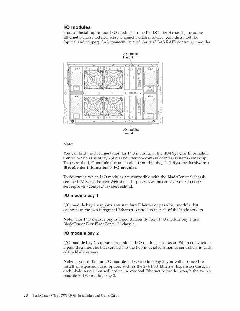
I/O modulesYou can install up to four I/O modules in the BladeCenter S chassis, includingEthernet switch modules, Fibre Channel switch modules, pass-thru modules(optical and copper), SAS connectivity modules, and SAS RAID controller modules.
I/O modules1 and 3
I/O modules2 and 4
! !
! !
Note:
You can find the documentation for I/O modules at the IBM Systems InformationCenter, which is at http://publib.boulder.ibm.com/infocenter/systems/index.jsp.To access the I/O module documentation from this site, click Systems hardware >BladeCenter information > I/O modules.
To determine which I/O modules are compatible with the BladeCenter S chassis,see the IBM ServerProven Web site at http://www.ibm.com/servers/eserver/serverproven/compat/us/eserver.html.
I/O module bay 1
I/O module bay 1 supports any standard Ethernet or pass-thru module thatconnects to the two integrated Ethernet controllers in each of the blade servers.
Note: This I/O module bay is wired differently from I/O module bay 1 in aBladeCenter E or BladeCenter H chassis.
I/O module bay 2
I/O module bay 2 supports an optional I/O module, such as an Ethernet switch ora pass-thru module, that connects to the two integrated Ethernet controllers in eachof the blade servers.
Note: If you install an I/O module in I/O module bay 2, you will also need toinstall an expansion card option, such as the 2/4 Port Ethernet Expansion Card, ineach blade server that will access the external Ethernet network through the switchmodule in I/O module bay 2.
20 BladeCenter S Type 7779/8886: Installation and User's Guide

I/O module bays 3 and 4
I/O module bays 3 and 4 support SAS connectivity modules or SAS RAIDcontroller modules.v If you are using the RAID storage solution, you must install two SAS RAID
controller modules, one in I/O module bay 3 and one in I/O module bay 4. SASRAID controller modules require a SAS expansion card option in each bladeserver that will access the integrated shared storage.
v If you are using only one SAS connectivity module, install the module in I/Omodule bay 3. You can install an additional SAS connectivity module in bay 4. ASAS connectivity module requires a SAS expansion card option in each bladeserver that will access the integrated shared storage.
The two bays also support Ethernet switch modules, Fibre Channel switchmodules, and pass-thru modules (optical and copper) if the disk storage modulesare not being used.
Important: I/O module bays 3 and 4 must both contain the same type of switch(either SAS connectivity modules, SAS RAID controller modules, Ethernet switchmodules, pass-thru modules, or Fibre Channel switch modules).
Power modulesThe BladeCenter S system supports up to four autoranging power modules thatare capable of supporting either 110 V ac or 220 V ac.
Power module
AC power LED
DC power LEDFault LED
There are two types of power modules. These power modules are identical exceptfor the power cord connector; one power module has a C14 connector and theother power module has a C20 connector. Both types of power modules can beinstalled in the same chassis.
Chapter 1. Introduction 21

Table 1. Power modules used in the BladeCenter S system
Power module with C14 connector
C14 connector
Power module with C20 connector
C20 connector
Within the BladeCenter S chassis, all power supplies are combined into a singlepower domain, which distributes power to each of the blade servers and modulesthrough the system midplane.
You must install a minimum of two power modules. If you install only two powermodules, install them in power module bays 1 and 2 (the top and bottom powermodule bays on the right as you face the rear of the BladeCenter S chassis).
Note: You must install all four power modules if you are using both disk storagemodules.
If you disengage or remove all devices from the front of the BladeCenter S chassis(media tray, blade servers, and disk storage modules), the power modules will bedisabled.
Indicators and controls
There are three LEDs on each power module:
AC powerLit (green). Power is being supplied to the power module.
DC powerLit (green). Power is being supplied from the power module to theBladeCenter S chassis midplane.
Fault Lit (amber). There is a fault with the power module.
Note: Before unplugging the AC power cord from the power module orremoving the power module from the BladeCenter S chassis, verify that thecapacity of the remaining power modules are sufficient to meet theminimum power requirements for all components in the BladeCenter Schassis. You can view power status and requirements through theadvanced management module.
For information on accessing and using the advanced managementmodule, see the Advanced Management Module User's Guide.1. Verify that the power modules are properly connected to an AC power
source. All power modules in the BladeCenter S chassis must be
22 BladeCenter S Type 7779/8886: Installation and User's Guide

connected to the same power input voltage (either 110 V ac or 220 Vac). Do not mix power input voltages.
2. Unplug the AC power cord from the power module and plug it inagain.
3. Reseat the power supply.4. Swap the AC power cord with a power cord that is known to be
working.5. Move the power module to another power module bay in the
BladeCenter S chassis.
Fan modulesThe BladeCenter S chassis comes with four installed hot-swap fan modules.
The fan modules (sometimes called fan packs) are designed to provide coolingairflow to the blade servers and I/O modules. Each fan module contains two fans.
Fan error LED
Indicators and controls
Each fan module has a single LED:
Error Lit (amber). One of the fans in the fan module has failed.
Note: If one of the fans in the fan module fails, the other fan will beginoperating at full speed.
Chapter 1. Introduction 23

Systems and storage managementIBM provides products that you can use to manage your BladeCenter S system andthe integrated shared storage that is available.
IBM DirectorIBM Director provides a comprehensive entry-level workgroup hardware manager.It includes advanced self-management capabilities for maximum systemavailability and support for multiple operating systems, including MicrosoftWindows, AIX, Linux, and i5/OS.
With IBM Director, a systems or network administrator can perform the followingtasks:v View and modify the hardware configuration of remote systemsv Monitor the usage, health, and performance of critical components, such as
microprocessors, disks, and memoryv Centrally manage individual or large groups of IBM and non-IBM
x86-processor-based servers, desktop computers, workstations, and notebookcomputers on a variety of platforms
v Inventory your environmentv Perform updates to managed systems, such as device drivers and firmwarev Automatically perform an action based on events or schedules, if IBM Director is
configured to do so
By deploying IBM Director, you can achieve reductions in ownership costs throughthe following benefits:v Reduced downtimev Increased productivity of IT personnel and usersv Reduced service and support costs
For more information about IBM Director and to download the latest version ofIBM Director, go to http://www.ibm.com/systems/management/director/.
Storage Configuration ManagerStorage Configuration Manager is a Web based device management application.
Storage Configuration Manager provides user and programmatic interfaces thatyou need to configure and monitor multiple instances of different types of storagerelated devices, including either the SAS connectivity modules or the SAS RAIDcontroller modules, and the SAS controllers on the expansion cards in each bladeserver. It includes a Web-based graphical user interface. It can be installed as astand-alone application or as an extension to IBM Director 5.20.2.
You can connect to the Storage Configuration Manager Manager component of theapplication from any computer on the network that it is installed on, using astandard Web browser (Internet Explorer 6.x or later, Firefox 1.0 or later).
Instead of using Storage Configuration Manager, you have the option ofconfiguring the integrated shared storage from the configuration wizard of theadvanced management module if you choose one of the predefined configurationsthat are provided. However, you must install Storage Configuration Manager ifyou decide to modify an existing configuration or create your own customizedconfiguration.
24 BladeCenter S Type 7779/8886: Installation and User's Guide

To download Storage Configuration Manager go to http://www.ibm.com/systems/support/management and select IBM Storage Configuration Manager.
Chapter 1. Introduction 25

26 BladeCenter S Type 7779/8886: Installation and User's Guide

Chapter 2. Installing the BladeCenter S Types 7779 and 8886
Install the BladeCenter S system in your facility by setting up and configuring allof the hardware components.
Before you begin the installation process, make sure that you have completed allplanning activities.
There are many different methods for setting up and configuring the componentsin your BladeCenter S system. In general, you must complete these procedures:1. Prepare to install the BladeCenter S system.2. Set up the BladeCenter S system hardware.3. Optionally, install IBM Director, if you are going to use it to manage your
BladeCenter S system.
Installation guidelinesBefore you remove or replace a component, read the following information.v Read Safety and “Handling static-sensitive devices” on page 28. This
information will help you work safely.v Observe good housekeeping in the area where you are working. Place removed
covers and other parts in a safe place.v You do not have to disconnect the BladeCenter S system from power to install or
replace any of the hot-swap modules. You must shut down the operating systemand turn off a hot-swap blade server before you remove it, but you do not haveto remove power from the BladeCenter S system itself.
v Do not attempt to lift an object that you think is too heavy for you. If you haveto lift a heavy object, observe the following precautions:– Make sure that you stand safely without slipping.– Distribute the weight of the object equally between your feet.– Use a slow lifting force. Never move suddenly or twist when you lift a heavy
object.– To avoid straining the muscles in your back, lift by standing or by pushing
up with your leg muscles.v Make sure that you have an adequate number of properly grounded electrical
outlets for the BladeCenter S system.v Back up all important data before you make changes to disk drives.v Have a small flat-blade screwdriver available.v Orange on a component or an orange label on or near a component indicates
that the component may be hot-swapped, which means that you can remove orinstall the component while the BladeCenter S system is running. (Orange canalso indicate touch points on hot-swap components.) See the instructions forremoving or installing a specific hot-swap component for any additionalprocedures that you might have to perform before you remove or install thecomponent.
v Blue on a component indicates touch points, where you can grip the componentto remove it from or install it in the BladeCenter S chassis, open or close a latch,and so on.
© Copyright IBM Corp. 2007, 2013 27

System reliability guidelinesTo help ensure proper system cooling and system reliability, make sure thefollowing requirements are met.v Each of the module bays on the front and rear of the BladeCenter S chassis has
either a module or a module bay filler installed in it.v Each of the blade bays on the front of the BladeCenter S chassis has either a
blade server or a blade bay filler installed in it.v Each of the disk storage module bays has a disk storage module or disk storage
module filler installed in it. If a disk storage module is installed, each of thedrive bays has a hard disk drive or a hard disk drive bay filler installed in it.
v Each of the drive bays in a blade server storage expansion option has either ahot-swap drive or a filler panel installed.
v You have followed the cabling instructions that come with optional adapters.v Cables for the optional modules are routed correctly.v A failed fan module is replaced as soon as possible.
Handling static-sensitive devicesMake sure that you read these guidelines before handing static-sensitive devices.
Attention: Static electricity can damage the BladeCenter S chassis and otherelectronic devices. To avoid damage, keep static-sensitive devices in theirstatic-protective packages until you are ready to install them.
To reduce the possibility of electrostatic discharge, observe the followingprecautions:v Limit your movement. Movement can cause static electricity to build up around
you.v The use of a grounding system is recommended. For example, wear an
electrostatic-discharge wrist strap, if one is available.v Handle the device carefully, holding it by its edges or its frame.v Do not touch solder joints, pins, or exposed circuitry.v Do not leave the device where others can handle and damage it.v While the device is still in its static-protective package, touch it to an unpainted
metal part of the BladeCenter S chassis or rack for at least 2 seconds. This drainsstatic electricity from the package and from your body.
v Remove the device from its package and install it immediately without settingdown the device. If it is necessary to set down the device, put it back into itsstatic-protective package.
v Take additional care when you handle devices during cold weather. Heatingreduces indoor humidity and increases static electricity.
28 BladeCenter S Type 7779/8886: Installation and User's Guide

Preparing to install your BladeCenter S systemUse this checklist to prepare for the installation of the BladeCenter S systemhardware.1. Verify that you have received all hardware.2. Obtain all firmware updates that you will need.3. Obtain configuration, systems management, and storage configuration software,
if needed.4. Review the Safety guidelines.
Verifying ship group contentsMake sure that you have received all of the hardware that you are expecting.
Depending on your order, you might receive several boxes. Each box might containone or more components.
You can use your order to confirm that you have received all of the boxes that youexpected to receive. To verify that you have received the required hardware in eachbox, complete the following steps:1. Open the packing list that is provided with each box.2. Confirm that the box contains all components that are listed on the packing list.
Obtaining firmware and device driversDuring the installation of the BladeCenter S system, you might have to update thefirmware for one or more of the components. Therefore, consider obtaining allfirmware updates before you begin the installation process.
The following BladeCenter S system components have firmware that can beupdated:v Advanced management modulev Blade serversv I/O modules, including the SAS connectivity module and the SAS RAID
controller modulev Disk storage modules
In addition, some of the optional hardware devices that you can order for theBladeCenter S system have device drivers that you must install.
For example, Ethernet controllers are integrated on each blade server system board.The Ethernet controllers provide 1000-Mbps full-duplex capability only, whichenables simultaneous transmission and reception of data to the external ports onthe Ethernet switches. You do not have to set any jumpers or configure thecontroller for the blade server operating system. However, you must install adevice driver in the blade server to enable the blade server operating system toaddress the Ethernet controller.
See the documentation that comes with your hardware options for informationabout installing any required device drivers.
To obtain the latest firmware and device drivers, complete the following steps:1. Go to http://www.ibm.com/systems/support/.2. Under Product Support, click BladeCenter.
Chapter 2. Installing the BladeCenter S Types 7779 and 8886 29

3. Under Popular links, select Software and device drivers.4. Select BladeCenter S to display the matrix of downloadable files.5. Select the blade servers and other devices that you will install in the
BladeCenter S chassis to download the firmware and device drivers.
Obtaining configuration, systems management, and storagemanagement software
IBM Director and Storage Configuration Manager are provided with theBladeCenter S system.
IBM Director
To obtain the latest version of IBM Director, go to the Support for IBM SystemsManagement Web site at http://www.ibm.com/systems/support/management.
Storage Configuration Manager
To obtain the latest version of Storage Configuration Manager, go to the Supportfor IBM Systems Management Web site at http://www.ibm.com/systems/support/management.
Setting up your BladeCenter S systemUse this checklist to set up the BladeCenter S system hardware.
Before you begin, make sure that you have at least 7 U of available space in yourrack to install the BladeCenter S chassis.1. Remove components that are installed in the BladeCenter S chassis to decrease
the weight, making it easier to install in a rack.2. Install the BladeCenter S chassis in a rack.3. Install the components that you removed (and any other components or
optional devices that you have ordered).4. Cable all components in the BladeCenter S chassis to the appropriate external
devices.5. Connect the BladeCenter S system to power.6. If you are installing IBM Director, set up the IBM Director server.
Removing componentsBefore you install the BladeCenter S chassis in a rack, remove components toreduce the weight of the unit so that it can safely be installed in the rack.
The weight of a fully populated BladeCenter S system is approximately 108.86 kg(240 lb). Attempting to lift this much weight can cause personal injury. Therefore,you should remove modules and blade servers from the BladeCenter S chassisbefore you attempt to install the unit in a rack. An empty BladeCenter S chassis(all modules and blade servers removed) is approximately 40.82 kg (90 lb).
30 BladeCenter S Type 7779/8886: Installation and User's Guide

Statement 32
CAUTION:To avoid personal injury, before lifting the unit, remove all the blades, powersupplies, and removable modules to reduce the weight.
108 kg(237 lbs)
(2X)
(6X) (4X)
(4X)
43.2 kg(95 lbs)
1. Remove components from the front of the BladeCenter S chassis.a. Read Safety and “Handling static-sensitive devices” on page 28.b. Remove all blade servers.
Important: Typically, you should record the bay location of the blade serverwhen you remove it so that you can reinstall it back in the same bay.However, when you initially receive the BladeCenter S system, theconfiguration that you choose for the zoning of the SAS connectivitymodules, if SAS connectivity modules are installed in the BladeCenter Schassis, dictates the correct location of the blade servers.
Releasehandles(open)
Bladeserver
Chapter 2. Installing the BladeCenter S Types 7779 and 8886 31

c. Remove all disk storage modules.Graphic showing the removal of a 6-disk storage module
Graphic showing the removal of a 12-disk storage module
2. Remove the bezel from the front of the BladeCenter S chassis.
32 BladeCenter S Type 7779/8886: Installation and User's Guide

Bezel
Release tabs
3. Remove components from the rear of the BladeCenter S chassis.a. Remove all power modules.
Power module 3
Power module 4
Release handle(open)
Chapter 2. Installing the BladeCenter S Types 7779 and 8886 33

b. Remove all fan modules.
FanerrorLED
Installing the BladeCenter S chassis in a rackUse the rack template and the rack installation kit that comes with the BladeCenterS system to correctly install it in a rack.
Before you begin, review the “Installation guidelines” on page 27.
If you are installing the BladeCenter S chassis in the Office Enablement Kit, see theOffice Enablement Kit Installation and User's Guide.
Rack requirements:
v Make sure that the room air temperature is below 35°C (95°F).v Do not block any air vents; usually, 15 cm (6 in.) of air space in the rear and 5
cm (2 in.) in the front provides proper airflow.v Three or more people are required to install the device in a rack.v Do not leave any unused U space within a rack open. Blank filler panels must
be used to prevent recirculation of warm air.v Install your BladeCenter S chassis only in a rack cabinet with perforated front
and rear doors or in a rack that is equipped with an IBM Rear Door HeateXchanger.
v Do not extend more than one device out of the rack at the same time.v Remove the rack doors and side panels to provide easier access during
installation.v The rack-mounting flanges must have holes and clearances per EIA-310-D.v Make sure that there is sufficient room in front of the front EIA flange to provide
minimum bezel clearance of 70 mm (2.76 inches) deep.v Make sure that there is sufficient room behind the rear of the rear EIA flanges to
provide for adequate cable management and routing.v Rack weight-handling capacity must be sufficient for the aggregate weight of the
BladeCenter S chassis, blade servers, power distribution units, and power cables.v The rack must be stabilized with stabilization brackets and leveling pads so that
it does not become unstable when it is fully populated.
To install the BladeCenter S chassis in a rack, complete the following steps:1. Read Safety and “Handling static-sensitive devices” on page 28.
34 BladeCenter S Type 7779/8886: Installation and User's Guide

2. Make sure that you have all of the parts of the rack installation kit that areneeded to install the BladeCenter S chassis in a rack. If any parts are missingor damaged, contact your place of purchase.
Rail(2)
Cable strap(6)
Rear of rail
Front of rail
M6 screws(14)
M5 screws(4)
Cable ties(6)
Clip nut(6)
Cage nut(6)
Upper Left shipping bracket
Upper Right shipping bracket
Note: Left and right shipping brackets are required only when theBladeCenter S chassis is shipped while it is installed in a rack cabinet. Aninitial set of shipping brackets is provided in the rack installation kit. If youneed to order additional shipping brackets, you must order the miscellaneousparts kit.
See the IBM BladeCenter S Type 8886 Problem Determination and Service Guide forthe Miscellaneous parts kit part number.
Chapter 2. Installing the BladeCenter S Types 7779 and 8886 35

3. Position the rack-mounting template that is supplied with your BladeCenter Ssystem on the rack so that the edges of the template do not overlap any otherinstalled devices. Line up and select the holes on the front and rear of the rackin the locations that are indicated by the arrows on the template.
Template
4. Use a screwdriver to install the cage nuts or the clip nuts, as required for yourrack, in the locations that are indicated on the template.
Note: For racks with square holes, use the cage nuts. For racks with roundholes, use the clip nuts.
Cagenut
Clipnut
36 BladeCenter S Type 7779/8886: Installation and User's Guide

5. Before you install the rails in the rack, fully extend each rail. A set of rail pinsand a mounting flange are on each end of the rail. Retract the rail pins bypressing in the rail latch �1� and then pulling the finger pull �2� toward thecenter of the rail.
Mounting flange
6. Pull each end of the rail away from its center until the rail is fully extended. Alocking mechanism prevents the rail from being extended too far.
7. Position the rail in the desired location on the rack and align the pins on eachend of the rail with the applicable holes on the rack �1�. Release the raillatches and finger pulls �2� on each end to allow the rail pins to pass throughthe rail and the mounting flange �3�. Repeat steps 5 through 7 for the otherrail.
Note: Make sure that the rail pins protrude through the mounting flanges andthe rack cabinet rails.
8. Remove the two blue shipping screws from each side of the BladeCenter Schassis.
Chapter 2. Installing the BladeCenter S Types 7779 and 8886 37

9. Slide the BladeCenter S chassis into the front of the rack. Insert one M6 screw�1� in the center hole of each rail on the rear of the rack cabinet.
Rear view
10. Optionally, install the shipping brackets. There is a set of shipping bracketsprovided in the BladeCenter S chassis rack installation kit.
Rear view
To install the upper right shipping bracket (if you are facing the rear of theBladeCenter S chassis):
38 BladeCenter S Type 7779/8886: Installation and User's Guide

a. Align the first shipping bracket so that the bottom of the shipping bracketwill fit into the slot to the right of power module bay 1. Insert theshipping bracket into the slot.
b. Align the holes in the shipping bracket with the holes in the rack cabinet.c. Secure the shipping bracket to the rack cabinet with the screws that are
provided.
Repeat these steps for the upper left shipping bracket.11. Insert four M6 screws in the front of the BladeCenter S chassis to secure it to
the rack cabinet.12. Install the bezel on the front of the BladeCenter S chassis.
Bezel
Installing componentsAfter you install the BladeCenter S chassis in a rack, install all components in theBladeCenter S chassis.
Installing the battery backup unitIf you are installing SAS RAID controller modules, you will also need to installtwo battery backup units. To install a battery backup unit, slide the unit into themedia tray and close the release handle.
Chapter 2. Installing the BladeCenter S Types 7779 and 8886 39

Media tray
Battery backup moduleBattery filler
1. Open the release handle (rotate the handle down).2. Slide the battery backup unit into the media tray.3. Close the release handle (rotate the handle up)
Installing a disk storage moduleTo install a disk storage module, open the release handles on the disk storagemodule and slide the disk storage module into the disk storage module bay. Then,you can install hard disk drives into the disk storage module by opening therelease handle on the hard disk drive and sliding the hard disk drive into the harddisk drive bay.
Note: Four power modules are required in the BladeCenter S chassis if two diskstorage modules are installed. If you are installing a disk storage module in diskstorage module bay 2, you must have power modules installed in power modulebays 3 and 4.
Graphic illustrating the installation of a 6-disk storage module
Fillerpanel
Drivecagefiller
Drive-trayassembly
Drivehandle
40 BladeCenter S Type 7779/8886: Installation and User's Guide

Graphic illustrating the installation of a 12-disk storage module
1. Read Safety and “Handling static-sensitive devices” on page 28.2. Open the release handles on the disk storage module (rotate the top handle up
and the bottom handle down).3. Slide the disk storage module into the disk storage module bay until it stops.4. Close the release handles (rotate the top handle down and the bottom handle
up).5. Install hard disk drives:
a. Open the release handle on the hard disk drive (rotate the handle up).b. Slide the hard disk drive into the disk storage module until it stops.
Important: If SAS connectivity modules are installed in the BladeCenter Schassis, the drive bay that you use is determined by the SAS connectivitymodule zoning configuration that you have selected for the BladeCenter Ssystem. Please note this only applies to the 6-disk storage module.
If SAS RAID controller modules are installed in the BladeCenter S chassis,make sure that you install SAS hard disk drives. SATA hard disk drives arenot currently supported when using SAS RAID controller modules.
c. Close the release handle (rotate the handle down).
Chapter 2. Installing the BladeCenter S Types 7779 and 8886 41

Installing a blade serverInstall a blade server in the front of the BladeCenter S chassis by opening the tworelease handles on the blade server, sliding the blade server into the blade serverbay, and closing the release handles. Before you install a blade server intoBladeCenter S chassis, make sure that you have installed any optional hardwaredevices, such as a SAS expansion card option, in the blade server.
You can find the documentation for blade servers in the IBM Systems InformationCenter, which is at http://publib.boulder.ibm.com/infocenter/systems/index.jsp.To access the blade server documentation from this site, click Systems hardware >BladeCenter information > Blade servers.
To determine which blade servers are compatible with the BladeCenter S chassis,see the IBM ServerProven Web site at http://www.ibm.com/servers/eserver/serverproven/compat/us/eserver.html.
Bladefiller
Releasehandles
Bladeserver
1. Read Safety and “Handling static-sensitive devices” on page 28.2. Select the bay for the blade server. Depending on the blade server type and the
optional devices that are installed in the blade server, two or more adjacentbays might be required.
Important: If SAS connectivity modules are installed, the blade server bay thatyou use when installing a blade server is determined by the SAS connectivitymodule zoning configuration that you have selected for the BladeCenter Ssystem. See the IBM BladeCenter S Type 8886 Planning Guide for moreinformation about zoning configuration.
3. Open both release handles (rotate the top handle up and the bottom handledown).
4. Slide the blade server into the blade server bay until it stops.5. Close both release handles (rotate the top handle down and the bottom handle
up).6. (Optional) Write identifying information on one of the labels that come with the
BladeCenter S chassis; then, place the label on the BladeCenter S chassis topbezel, just above the blade server.
42 BladeCenter S Type 7779/8886: Installation and User's Guide

Important: Do not place the label on the blade server or in any way block theventilation holes on the bezel.
Installing a serial pass-thru moduleInstall a serial pass-thru module in the rear of the BladeCenter S chassis byopening the release handle and sliding the serial pass-thru module into the modulebay.
Modulefiller
Releasehandle
Serialpass-thrumodule
1. Read Safety and “Handling static-sensitive devices” on page 28.2. Open the release handle (rotate the handle down).3. Slide the module into the serial pass-thru module bay until it stops.4. Close the release handle (rotate the handle up).
Installing an advanced management moduleTo install an advanced management module, open the release handle on themodule and slide it into the advanced management module module bay.
Chapter 2. Installing the BladeCenter S Types 7779 and 8886 43

Advancedmanagementmodule
Release handle
1. Read Safety and “Handling static-sensitive devices” on page 28.2. Open the release handle (rotate the handle down).3. Slide the advanced management module into the advanced management
module bay until it stops.4. Close the release handle (rotate the handle up).
Installing a power moduleTo install a power module, open the release handle, slide the power module intothe power module bay, and close the release handle.
Note: On the rear of the power module, there is a plastic strain-relief tie thatshould not be removed.
Power modulefillers
Power module 3
Power module 4
1. Read Safety and “Handling static-sensitive devices” on page 28.
44 BladeCenter S Type 7779/8886: Installation and User's Guide

2. Open the release handle (rotate the handle down).3. Slide the module into the power module bay until it stops.4. Close the release handle (rotate the handle up).
Installing a fan moduleTo install a fan module, slide it into the fan module bay until the fan handle locks.
1. Read Safety and “Handling static-sensitive devices” on page 28.2. Slide the module into the fan module bay until the fan handle locks.
Installing an I/O moduleTo install an I/O module, open the release handle, slide the module into the I/Omodule bay of the BladeCenter S chassis. Before installing an I/O module, readany installation instructions that comes with that I/O module.
Modulefiller
Releasehandle(open)
I/Omodule
Note:
You can find the documentation for I/O modules at the IBM Systems InformationCenter, which is at http://publib.boulder.ibm.com/infocenter/systems/index.jsp.To access the I/O module documentation from this site, click Systems hardware >BladeCenter information > I/O modules.
Chapter 2. Installing the BladeCenter S Types 7779 and 8886 45

To determine which I/O modules are compatible with the BladeCenter S chassis,see the IBM ServerProven Web site at http://www.ibm.com/servers/eserver/serverproven/compat/us/eserver.html.1. Read Safety and “Handling static-sensitive devices” on page 28.2. Open the release handle (rotate the handle down).3. Slide the module into the module bay until it stops.4. Close the release handle (rotate the handle up).
The placement of the I/O module in the BladeCenter S chassis depends on thetype of I/O module being installed. For example, an Ethernet switch module istypically deployed in I/O module bay 1 or I/O module bay 2. SAS connectivitymodules or SAS RAID controller modules are deployed in I/O module bays 3 and4.
Note:
v If you install an Ethernet switch module in I/O module bay 2, you must alsoinstall an expansion card option, such as the 2/4 Port Ethernet Expansion Card,in each of the blade servers that will access the Ethernet network through thatI/O module.
v If you install SAS connectivity modules , you must also install a SAS expansioncard option in each of the blade servers that will access the integrated sharedstorage. You can install SAS or SATA hard disk drives in the disk storagemodules.
v If you install SAS RAID controller modules, you must also install a SASexpansion card option in each of the blade servers that will access the integratedshared storage. In addition, you must install SAS hard disk drives in the diskstorage modules.
Cabling the BladeCenter S chassisAttach all cables to the rear of the BladeCenter S chassis and secure them to therack cabinet rails.1. Attach the power cords and other cables to the rear of the BladeCenter S
chassis.
Up to three sets of power cords are provided with the BladeCenter S system.Use the power cords that you need for your environment.
2. Route the power cables through the plastic strain-relief ties.
46 BladeCenter S Type 7779/8886: Installation and User's Guide

3. Route all cables along the rack cabinet rails.
Important: Allow slack in all cables to avoid tension in the cables and to allowyou to remove adjacent modules from the BladeCenter S chassis withouthaving to remove the cables.
4. Use the cable ties and cable straps to secure the cables together and attachthem to the rack cabinet rails.
Connecting the BladeCenter S chassis to powerPower is supplied to the BladeCenter S chassis when you connect one end of eachpower cord to a power connector on the rear of the BladeCenter S chassis and theother end of each power cord to a power distribution unit (PDU) or appropriateelectrical outlet. The BladeCenter S chassis does not have a power switch.
After you connect and route the cables, supply power to the BladeCenter S chassisand verify that it is working correctly:1. Connect each power cord from the power supplies to a 110 V ac or 220 V ac
PDU or electrical outlet.2. Verify that the following LEDs are lit:
v The power-on LED on the system LED panel.v The dc power and ac power LEDs on each power module.v The OK LED on the advanced management module.v The OK or Power LED on each I/O module.
Note: Initially, the port fault LEDs on the SAS connectivity module might beflashing amber because the external ports are disabled by default. The portswill be enabled when you complete the initial configuration of the advancedmanagement module.
v The power-on LED on each blade server. You might have to turn on eachblade server separately.
Disconnecting power from the BladeCenter unitDisconnect power from the BladeCenter S chassis by shutting down all bladeservers and disconnecting the BladeCenter S chassis from all power sources.1. Shut down each blade server. See the documentation that comes with your
blade server for information about shutting down the operating system on theblade server.
2. Disconnect all power cords on the BladeCenter unit from the power connectors.
Note: After you disconnect the BladeCenter S chassis from power, wait at least5 seconds before you connect the BladeCenter S chassis to power again.
Chapter 2. Installing the BladeCenter S Types 7779 and 8886 47

48 BladeCenter S Type 7779/8886: Installation and User's Guide

Chapter 3. Installing IBM Director Server (optional)
IBM Director is a comprehensive systems manager that is designed for use acrossthe full IBM Systems server family, including BladeCenter systems. An integrated,easy-to-use suite of tools, IBM Director provides clients with flexiblesystems-management abilities to help maximize system availability and lower ITcosts. With IBM Director, IT administrators can view and track the hardwareconfiguration of remote systems and monitor the component performance ofmicroprocessors, disks, and memory.
IBM Director communicates with the advanced management module through theEthernet port on the advanced management module. If you are going to use IBMDirector to manage your BladeCenter S system, make sure that it is installed on aserver that meets the documented system requirements and that the advancedmanagement module is on a network that is reachable from the IBM Directorserver.
Note: IBM Director communicates over the TCP command mode port. You mighthave to increase the maximum number of simultaneous connections that can bemade over this port to prevent conflicts with other applications. You can modifythe setting through the advanced management module Web interface (NetworkProtocols page).
IBM Director has the capability to use the zone configurations that you create withStorage Configuration Manager. You can use Storage Configuration Manager tocreate an initial zone configuration for a BladeCenter S system and use IBMDirector to distribute the configuration to other BladeCenter S systems.
Note: For more information about Storage Configuration Manager, see the IBMStorage Configuration Manager Planning, Installation, and Configuration Guide.
To download the latest version of IBM Director, go to http://www.ibm.com/systems/support/management and select Product Family.
© Copyright IBM Corp. 2007, 2013 49

50 BladeCenter S Type 7779/8886: Installation and User's Guide

Chapter 4. Configuring the BladeCenter S system
Configuring the BladeCenter S system involves performing all of the tasks that arenecessary to set up a functioning BladeCenter S system on which you can begin toinstall applications.
Before you configure the BladeCenter S system, make sure that you havecompleted all installation activities.
After you have completed the initial configuration, you can begin to install andconfigure applications.
You can also optionally install Storage Configuration Manager to manage the SASconnectivity modules or SAS RAID controller modules and integrated sharedstorage.
Configuring I/O modulesYou must enable at least one external port on an Ethernet switch module in I/Omodule bay 1 to communicate with the Ethernet controllers that are integrated ineach blade server.
There are two ways to access an I/O module to configure it:v Using a Web browser and accessing the Web interface for the I/O module, using
its IP address. You can obtain the IP address from the System Status page of theadvanced management module Web interface.
v Using a program such as Telnet and accessing the command-line interface (CLI)for the I/O module, using its IP address.
To configure an I/O module, complete the following steps:1. Access the I/O module, using its IP address.2. Configure the I/O module. See the documentation that comes with the I/O
module for information about configuration.3. Update the firmware for the I/O module, if necessary. See the documentation
that comes with the I/O module for information about updating firmware.
Note: If a pass-thru module is installed in I/O module bay 1, you must configurethe network switch that the pass-thru module is connected to. See thedocumentation that comes with the network switch for more information.
You can find the documentation for I/O modules at the IBM Systems InformationCenter, which is at http://publib.boulder.ibm.com/infocenter/systems/index.jsp.To access the I/O module documentation from this site, click Systems hardware >BladeCenter information > I/O modules.
To determine which I/O modules are compatible with the BladeCenter S chassis,see the IBM ServerProven Web site at http://www.ibm.com/servers/eserver/serverproven/compat/us/eserver.html.
© Copyright IBM Corp. 2007, 2013 51

Configuring blade serversConfiguring a blade server involves setting up the SAS storage, installing theoperating system, and updating the firmware.
Be sure to refer to the documentation for the blade server that you are configuring.It contains specific instructions that might differ slightly from those listed in thissection.
For more information about blade servers, see the IBM Systems InformationCenter, which is at http://publib.boulder.ibm.com/infocenter/systems/index.jsp.To access the blade server documentation from this site, click Systems hardware >BladeCenter information > Blade servers.
Although there are several ways to access the blade server, consider using KVMaccess when you perform the initial setup of a blade server. Attach a monitor tothe video connector on the advanced management module. Attach a USB keyboardand mouse to the USB connectors on the advanced management module or theUSB connectors on the media tray.
Note: If you are using KVM, you must press the on the blade server thatyou are configuring to assign the monitor and keyboard to the blade server.1. Update the firmware for the blade server. See the documentation that comes
with the blade server form information about updating firmware.2. Start the blade server.3. Optionally use the LSI configuration utility on the blade server to set the SAS
hard disk drive configuration if you are installing SAS connectivity modules.You can implement integrated mirroring (IM), integrated mirroring enhanced(IME), or integrated striping (IS) for the hard disk drives.
Note: In addition to the LSI configuration utility, you can use MegaRAIDStorage Manager (available on CD with the SAS expansion card option), or theServerGuide program to configure your SAS storage.a. Some blade servers, such as the HS21 and LS21, might have two SAS
controllers, one for the internal SAS controller (called Planar SAS) and onefor the SAS expansion card. You must first access BIOS to either disable theinternal SAS controller or the option ROM for the SAS expansion card.v If no hard disk drives are installed in the blade server, disable the
internal SAS controller:1) When you are prompted, press F1 to access BIOS.2) Select Device and I/O ports.3) Disable the Planar SAS.
v If hard disk drives are installed in the blade server, disable the optionROM for the SAS expansion card:1) When you are prompted, press F1 to access BIOS.2) Select Advanced Setup > PCI Control > PCI ROM.3) Disable the Option ROM for the SAS expansion card slot.
For more information about setting up the SAS hard disk driveconfiguration, see the IBM BladeCenter SAS Expansion Card (CFFv) Installationand User's Guide.
b. Save the BIOS configuration and restart the blade server.
52 BladeCenter S Type 7779/8886: Installation and User's Guide

c. When you are prompted, press Ctrl-C to start the LSI Configuration Utility.d. Select the SAS expansion adapter and complete the following steps:
1) Select RAID Properties.2) Select the type of volume that is to be created (IM Volume, IME Volume,
or IS Volume) and follow the prompts.e. After you create the volumes, exit the LSI Configuration Utility.
4. Assign the DVD drive on the media tray to the blade server that you are
configuring by pressing CD on the front of the blade server.For more information about assigning the media tray to the blade server, see“Selecting shared BladeCenter resources.”
5. Insert the operating system media into the DVD drive.6. Set the DVD drive as the boot device for the blade server that you are
configuring, if it is necessary for that blade server. You can do that from theadvanced management module.
7. Install the operating system. The ServerGuide program is a server installationassistant that simplifies the process of installing and configuring blade servers.If you are installing a Microsoft Windows operating system, consider using theServerGuide CD that comes with your blade server. If you have alreadyconfigured your SAS storage before using the ServerGuide program, make surethat you choose to retain the configuration when you begin installing theoperating system.
Important: If you have two SAS connectivity modules installed, the bladeserver does not have internal hard disk drives installed, and you are installingthe operating system one on of the disks or disk arrays in the storage modules:a. From the advanced management module Web interface, disable the ports
for one of the SAS connectivity modules.b. Install the operating system to the disk or disk array.c. From the advanced management module Web interface, re-enable the ports
for the SAS connectivity module.
If you are using IBM Director and RDM, these steps are performed by thesoftware; you do not need to perform these steps.
Selecting shared BladeCenter resourcesSome BladeCenter resources are selectable for use by a single blade server at atime, such as the media tray or the keyboard-video-mouse (KVM).
BladeCenter resources such as power modules, cooling, system management, andnetwork I/O modules are available to most blade servers at all times; no userintervention is required. You can select the resources for a blade server in thefollowing ways.
Chapter 4. Configuring the BladeCenter S system 53

Attention: Do not switch ownership of the media tray to another blade serverwhile a transaction is taking place on the DVD drive or an attached USB device.The data might become corrupted. Make sure that activity lights on the DVD driveare not lit.v Most blade servers have two selection buttons on the front of the blade server
CD and .v You can use the advanced management module Web interface to enable or
disable the selection on the blade servers and change ownership of the mediatray or the KVM (Blade Tasks > Remote Control).The monitor that is attached to the advanced management module shows thevideo output from the blade server that is the current owner of the KVM.
– To switch the KVM to a specific blade server, press the button on thatblade server.
– To switch ownership of the media tray to a specific blade server, press the
CD button on that blade server.The BladeCenter S Types 7779 and 8886 assigns the resource to the blade serverthat is requesting it.
v On a keyboard that is directly attached to the advanced management module,you can press keyboard keys in the following sequence to switch KVM controlbetween blade servers:
NumLock NumLock blade_server_number EnterWhere blade_server_number is the two-digit number for the blade bay in whichthe blade server is installed. When you use some keyboards, such as the 28L3644(37L0888) keyboard, you must hold down the Shift key while you enter this keysequence.
It can take up to 20 seconds for the operating system in the switched-to bladeserver to recognize the media tray or the KVM. If you install Microsoft Windows2000 on a blade server while it is not the current owner of the media tray or theKVM, the first time the blade server requests ownership after the operating systemhas been installed, it can take up to 1 minute for the operating system to recognizethe devices (this is a one-time-only occurrence).
Note: The operating system on the blade server must provide USB support for theblade server to recognize and use the media tray. The BladeCenter S system usesUSB for internal communication with these devices.
54 BladeCenter S Type 7779/8886: Installation and User's Guide

Appendix A. Getting help and technical assistance
If you need help, service, or technical assistance or just want more informationabout IBM products, you will find a wide variety of sources available from IBM toassist you.
Use this information to obtain additional information about IBM and IBMproducts, determine what to do if you experience a problem with your IBM systemor optional device, and determine whom to call for service, if it is necessary.
Before you callBefore you call, make sure that you have taken these steps to try to solve theproblem yourself.
If you believe that you require IBM to perform warranty service on your IBMproduct, the IBM service technicians will be able to assist you more efficiently ifyou prepare before you call.v Check all cables to make sure that they are connected.v Check the power switches to make sure that the system and any optional
devices are turned on.v Check for updated software, firmware, and operating-system device drivers for
your IBM product. The IBM Warranty terms and conditions state that you, theowner of the IBM product, are responsible for maintaining and updating allsoftware and firmware for the product (unless it is covered by an additionalmaintenance contract). Your IBM service technician will request that youupgrade your software and firmware if the problem has a documented solutionwithin a software upgrade.
v If you have installed new hardware or software in your environment, check thehttp://www.ibm.com/systems/info/x86servers/serverproven/compat/us/ IBMServerProven website to make sure that the hardware and software is supportedby your IBM product.
v Go to the http://www.ibm.com/supportportal/ IBM Support Portal to check forinformation to help you solve the problem.
v Gather the following information to provide to IBM Support. This data will helpIBM Support quickly provide a solution to your problem and ensure that youreceive the level of service for which you might have contracted.– Hardware and Software Maintenance agreement contract numbers, if
applicable– Machine type number (IBM 4-digit machine identifier)– Model number– Serial number– Current system UEFI and firmware levels– Other pertinent information such as error messages and logs
v Go to the http://www.ibm.com/support/electronic/portal/ IBM ElectronicServices website to submit an Electronic Service Request. Submitting anElectronic Service Request will start the process of determining a solution toyour problem by making the pertinent information available to IBM Support
© Copyright IBM Corp. 2007, 2013 55

quickly and efficiently. IBM service technicians can start working on yoursolution as soon as you have completed and submitted an Electronic ServiceRequest.
You can solve many problems without outside assistance by following thetroubleshooting procedures that IBM provides in the online help or in thedocumentation that is provided with your IBM product. The documentation thatcomes with IBM systems also describes the diagnostic tests that you can perform.Most systems, operating systems, and programs come with documentation thatcontains troubleshooting procedures and explanations of error messages and errorcodes. If you suspect a software problem, see the documentation for the operatingsystem or program.
Using the documentationInformation about your IBM system and preinstalled software, if any, or optionaldevice is available in the documentation that comes with the product. Thatdocumentation can include printed documents, online documents, readme files,and help files.
See the troubleshooting information in your system documentation for instructionsfor using the diagnostic programs. The troubleshooting information or thediagnostic programs might tell you that you need additional or updated devicedrivers or other software. IBM maintains pages on the World Wide Web where youcan get the latest technical information and download device drivers and updates.To access these pages, go to the http://www.ibm.com/supportportal/ IBMSupport Portal .
Getting help and information from the World Wide WebUp-to-date information about IBM products and support is available on the WorldWide Web.
On the World Wide Web, up-to-date information about IBM systems, optionaldevices, services, and support is available at the http://www.ibm.com/supportportal/ IBM Support Portal . IBM System x information is at thehttp://www.ibm.com/systems/x/ IBM System x website . IBM BladeCenterinformation is at the http://www.ibm.com/systems/bladecenter/ IBMBladeCenter website . IBM IntelliStation information is at the http://www.ibm.com/systems/intellistation/ IBM Workstations website .
How to send DSA data to IBMUse the IBM Enhanced Customer Data Repository to send diagnostic data to IBM.
56 BladeCenter S Type 7779/8886: Installation and User's Guide

Before you send diagnostic data to IBM, read the terms of use athttp://www.ibm.com/de/support/ecurep/send_http.html Enhanced CustomerData Repository terms of use .
You can use any of the following methods to send diagnostic data to IBM:v Standard upload: http://www.ibm.com/de/support/ecurep/send_http.html
Enhanced Customer Data Repository standard upload websitev Standard upload with the system serial number: http://www.ecurep.ibm.com/
app/upload_hw/ Standard Upload websitev Secure upload: http://www.ibm.com/de/support/ecurep/
send_http.html#secure Enhanced Customer Data Repository secure uploadwebsite
v Secure upload with the system serial number: https://www.ecurep.ibm.com/app/upload_hw/ Secure Upload website
Creating a personalized support web pageYou can create a personalized support web page by identifying IBM products thatare of interest to you.
To create a personalized support web page, go to the http://www.ibm.com/support/mysupport/ IBM Registration website . From this personalized page, youcan subscribe to weekly email notifications about new technical documents, searchfor information and downloads, and access various administrative services.
Software service and supportThrough IBM Support Line, you can get telephone assistance, for a fee, with usage,configuration, and software problems with your IBM products.
For information about which products are supported by Support Line in yourcountry or region, see the http://www.ibm.com/services/supline/products/ IBMSupport Line Supported Product List website .
For more information about Support Line and other IBM services, see thehttp://www.ibm.com/services/ IBM IT Services website or see thehttp://www.ibm.com/planetwide/ “Directory of worldwide contacts” website forsupport telephone numbers. In the U.S. and Canada, call 1-800-IBM-SERV(1-800-426-7378).
Hardware service and supportYou can receive hardware service through your IBM reseller or IBM Services.
Appendix A. Getting help and technical assistance 57

To locate a reseller authorized by IBM to provide warranty service, go to thehttp://www.ibm.com/partnerworld/ IBM PartnerWorld website and click FindBusiness Partners on the right side of the page. For IBM support telephonenumbers, see the http://www.ibm.com/planetwide/ “Directory of worldwidecontacts” website . In the U.S. and Canada, call 1-800-IBM-SERV (1-800-426-7378).
In the U.S. and Canada, hardware service and support is available 24 hours a day,7 days a week. In the U.K., these services are available Monday through Friday,from 9 a.m. to 6 p.m.
IBM Taiwan product serviceUse this information to contact IBM Taiwan product service.
IBM Taiwan product service contact information:
IBM Taiwan Corporation3F, No 7, Song Ren Rd.Taipei, TaiwanTelephone: 0800-016-888
58 BladeCenter S Type 7779/8886: Installation and User's Guide

Appendix B. Parts listing
These illustrations identify the replaceable components that are available for theBladeCenter S Types 7779 and 8886 unit.v Consumable part. Purchase and replacement of consumable parts (components,
such as batteries and printer cartridges, that have depletable life) is yourresponsibility. If IBM acquires or installs a consumable part at your request, youwill be charged for the service.
v Tier 1 customer replaceable unit (CRU). Replacement of Tier 1 CRUs is yourresponsibility. If IBM installs a Tier 1 CRU at your request, you will be chargedfor the installation.
v Tier 2 customer replaceable unit. You can install a Tier 2 CRU yourself orrequest IBM to install it, at no additional charge, under the type of warrantyservice that is designed for your computer.
v Field replaceable unit (FRU). FRUs must be installed only by trained servicetechnicians.
Front view parts listingThe front of the BladeCenter S chassis contains components such as the media trayand bays for disk storage modules and blade servers.
See the IBM BladeCenter S Type 8886 Problem Determination and Service Guide for partnumbers.
© Copyright IBM Corp. 2007, 2013 59

Index Description
1 Chassis shell (without shuttle)
2 Filler, blade server
3 Media tray
4 DVD drive
5 Bezel
6 Filler, 2.5" hard disk drive
7 12-disk disk storage module
8 Filler, 3.5" disk storage module
9 Filler, disk storage module
10 6-disk disk storage module
Consumable parts (parts that are purchased separately) are not covered by the IBMStatement of Limited Warranty. The following consumable parts are available forpurchase from the retail store.
Index Description Part number
Battery backup unit 45W5002
Rear view parts listingThe rear of the BladeCenter S chassis contains components such as themanagement module, fan modules, and I/O modules.
1
2
3
4
5
6
7
8
See the IBM BladeCenter S Types 7779 and 8886 Problem Determination and ServiceGuide for part numbers.
60 BladeCenter S Type 7779/8886: Installation and User's Guide
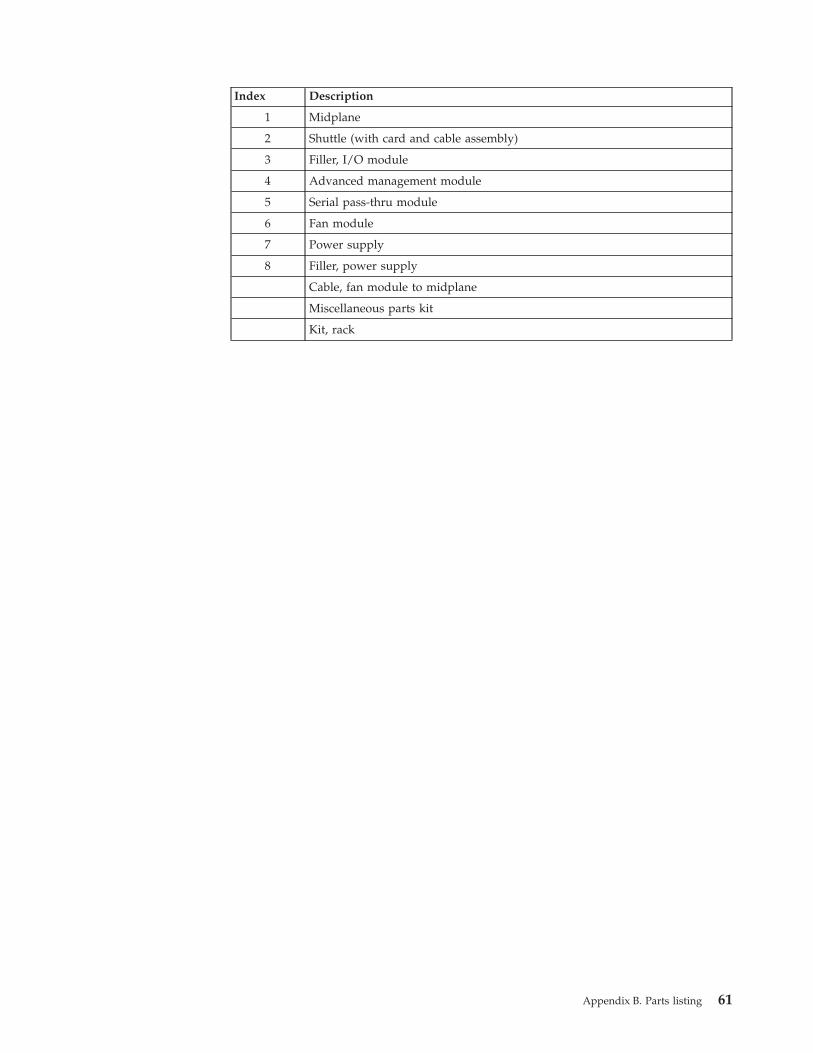
Index Description
1 Midplane
2 Shuttle (with card and cable assembly)
3 Filler, I/O module
4 Advanced management module
5 Serial pass-thru module
6 Fan module
7 Power supply
8 Filler, power supply
Cable, fan module to midplane
Miscellaneous parts kit
Kit, rack
Appendix B. Parts listing 61

62 BladeCenter S Type 7779/8886: Installation and User's Guide

Notices
This information was developed for products and services offered in the U.S.A.
IBM may not offer the products, services, or features discussed in this document inother countries. Consult your local IBM representative for information on theproducts and services currently available in your area. Any reference to an IBMproduct, program, or service is not intended to state or imply that only that IBMproduct, program, or service may be used. Any functionally equivalent product,program, or service that does not infringe any IBM intellectual property right maybe used instead. However, it is the user's responsibility to evaluate and verify theoperation of any non-IBM product, program, or service.
IBM may have patents or pending patent applications covering subject matterdescribed in this document. The furnishing of this document does not give youany license to these patents. You can send license inquiries, in writing, to:
IBM Director of LicensingIBM CorporationNorth Castle DriveArmonk, NY 10504-1785U.S.A.
INTERNATIONAL BUSINESS MACHINES CORPORATION PROVIDES THISPUBLICATION “AS IS” WITHOUT WARRANTY OF ANY KIND, EITHEREXPRESS OR IMPLIED, INCLUDING, BUT NOT LIMITED TO, THE IMPLIEDWARRANTIES OF NON-INFRINGEMENT, MERCHANTABILITY OR FITNESSFOR A PARTICULAR PURPOSE. Some states do not allow disclaimer of express orimplied warranties in certain transactions, therefore, this statement may not applyto you.
This information could include technical inaccuracies or typographical errors.Changes are periodically made to the information herein; these changes will beincorporated in new editions of the publication. IBM may make improvementsand/or changes in the product(s) and/or the program(s) described in thispublication at any time without notice.
Any references in this information to non-IBM websites are provided forconvenience only and do not in any manner serve as an endorsement of thosewebsites. The materials at those websites are not part of the materials for this IBMproduct, and use of those websites is at your own risk.
IBM may use or distribute any of the information you supply in any way itbelieves appropriate without incurring any obligation to you.
© Copyright IBM Corp. 2007, 2013 63

TrademarksIBM, the IBM logo, and ibm.com are trademarks of International BusinessMachines Corp., registered in many jurisdictions worldwide. Other product andservice names might be trademarks of IBM or other companies.
A current list of IBM trademarks is available on the web at “Copyright andtrademark information” atthe http://www.ibm.com/legal/copytrade.shtml“Copyright and trademark information” website .
Adobe and PostScript are either registered trademarks or trademarks of AdobeSystems Incorporated in the United States and/or other countries.
Cell Broadband Engine is a trademark of Sony Computer Entertainment, Inc., inthe United States, other countries, or both and is used under license therefrom.
Intel, Intel Xeon, Itanium, and Pentium are trademarks or registered trademarks ofIntel Corporation or its subsidiaries in the United States and other countries.
Java and all Java-based trademarks and logos are trademarks or registeredtrademarks of Oracle and/or its affiliates.
Linux is a registered trademark of Linus Torvalds in the United States, othercountries, or both.
Microsoft, Windows, and Windows NT are trademarks of Microsoft Corporation inthe United States, other countries, or both.
UNIX is a registered trademark of The Open Group in the United States and othercountries.
Important notesProcessor speed indicates the internal clock speed of the microprocessor; otherfactors also affect application performance.
CD or DVD drive speed is the variable read rate. Actual speeds vary and are oftenless than the possible maximum.
When referring to processor storage, real and virtual storage, or channel volume,KB stands for 1024 bytes, MB stands for 1,048,576 bytes, and GB stands for1,073,741,824 bytes.
When referring to hard disk drive capacity or communications volume, MB standsfor 1,000,000 bytes, and GB stands for 1,000,000,000 bytes. Total user-accessiblecapacity can vary depending on operating environments.
Maximum internal hard disk drive capacities assume the replacement of anystandard hard disk drives and population of all hard disk drive bays with thelargest currently supported drives that are available from IBM.
Maximum memory might require replacement of the standard memory with anoptional memory module.
Each solid-state memory cell has an intrinsic, finite number of write cycles that thecell can incur. Therefore, a solid-state device has a maximum number of write
64 BladeCenter S Type 7779/8886: Installation and User's Guide

cycles that it can be subjected to, expressed as “total bytes written” (TBW). Adevice that has exceeded this limit might fail to respond to system-generatedcommands or might be incapable of being written to. IBM is not responsible forreplacement of a device that has exceeded its maximum guaranteed number ofprogram/erase cycles, as documented in the Official Published Specifications forthe device.
IBM makes no representation or warranties regarding non-IBM products andservices that are ServerProven, including but not limited to the implied warrantiesof merchantability and fitness for a particular purpose. These products are offeredand warranted solely by third parties.
IBM makes no representations or warranties with respect to non-IBM products.Support (if any) for the non-IBM products is provided by the third party, not IBM.
Some software might differ from its retail version (if available) and might notinclude user manuals or all program functionality.
Particulate contaminationAttention: Airborne particulates (including metal flakes or particles) and reactivegases acting alone or in combination with other environmental factors such ashumidity or temperature might pose a risk to the device that is described in thisdocument.
Risks that are posed by the presence of excessive particulate levels orconcentrations of harmful gases include damage that might cause the device tomalfunction or cease functioning altogether. This specification sets forth limits forparticulates and gases that are intended to avoid such damage. The limits must notbe viewed or used as definitive limits, because numerous other factors, such astemperature or moisture content of the air, can influence the impact of particulatesor environmental corrosives and gaseous contaminant transfer. In the absence ofspecific limits that are set forth in this document, you must implement practicesthat maintain particulate and gas levels that are consistent with the protection ofhuman health and safety. If IBM determines that the levels of particulates or gasesin your environment have caused damage to the device, IBM may conditionprovision of repair or replacement of devices or parts on implementation ofappropriate remedial measures to mitigate such environmental contamination.Implementation of such remedial measures is a customer responsibility.
Table 2. Limits for particulates and gases
Contaminant Limits
Particulate v The room air must be continuously filtered with 40% atmosphericdust spot efficiency (MERV 9) according to ASHRAE Standard 52.21.
v Air that enters a data center must be filtered to 99.97% efficiency orgreater, using high-efficiency particulate air (HEPA) filters that meetMIL-STD-282.
v The deliquescent relative humidity of the particulate contaminationmust be more than 60%2.
v The room must be free of conductive contamination such as zincwhiskers.
Gaseous v Copper: Class G1 as per ANSI/ISA 71.04-19853
v Silver: Corrosion rate of less than 300 Å in 30 days
Notices 65

Table 2. Limits for particulates and gases (continued)
Contaminant Limits
1. ASHRAE 52.2-2008 - Method of Testing General Ventilation Air-Cleaning Devices forRemoval Efficiency by Particle Size. Atlanta: American Society of Heating, Refrigeratingand Air-Conditioning Engineers, Inc.
2. The deliquescent relative humidity of particulate contamination is the relative humidityat which the dust absorbs enough water to become wet and promote ionic conduction.
3. ANSI/ISA-71.04-1985. Environmental conditions for process measurement and controlsystems: Airborne contaminants. Instrument Society of America, Research Triangle Park,North Carolina, U.S.A.
Documentation formatThe publications for this product are in Adobe Portable Document Format (PDF)and should be compliant with accessibility standards. If you experience difficultieswhen you use the PDF files and want to request a web-based format or accessiblePDF document for a publication, direct your mail to the following address:
Information DevelopmentIBM Corporation205/A0153039 E. Cornwallis RoadP.O. Box 12195Research Triangle Park, North Carolina 27709-2195U.S.A.
In the request, be sure to include the publication part number and title.
When you send information to IBM, you grant IBM a nonexclusive right to use ordistribute the information in any way it believes appropriate without incurring anyobligation to you.
Telecommunication regulatory statement
This product may not be certified in your country for connection by any meanswhatsoever to interfaces of public telecommunications networks. Furthercertification may be required by law prior to making any such connection. Contactan IBM representative or reseller for any questions.
Electronic emission noticesWhen you attach a monitor to the equipment, you must use the designatedmonitor cable and any interference suppression devices that are supplied with themonitor.
66 BladeCenter S Type 7779/8886: Installation and User's Guide

Federal Communications Commission (FCC) statementNote: This equipment has been tested and found to comply with the limits for aClass A digital device, pursuant to Part 15 of the FCC Rules. These limits aredesigned to provide reasonable protection against harmful interference when theequipment is operated in a commercial environment. This equipment generates,uses, and can radiate radio frequency energy and, if not installed and used inaccordance with the instruction manual, may cause harmful interference to radiocommunications. Operation of this equipment in a residential area is likely to causeharmful interference, in which case the user will be required to correct theinterference at his own expense.
Properly shielded and grounded cables and connectors must be used in order tomeet FCC emission limits. IBM is not responsible for any radio or televisioninterference caused by using other than recommended cables and connectors or byunauthorized changes or modifications to this equipment. Unauthorized changesor modifications could void the user's authority to operate the equipment.
This device complies with Part 15 of the FCC Rules. Operation is subject to thefollowing two conditions: (1) this device may not cause harmful interference, and(2) this device must accept any interference received, including interference thatmight cause undesired operation.
Industry Canada Class A emission compliance statementThis Class A digital apparatus complies with Canadian ICES-003.
Avis de conformité à la réglementation d'Industrie CanadaCet appareil numérique de la classe A est conforme à la norme NMB-003 duCanada.
Australia and New Zealand Class A statementAttention: This is a Class A product. In a domestic environment this product maycause radio interference in which case the user may be required to take adequatemeasures.
European Union EMC Directive conformance statementThis product is in conformity with the protection requirements of EU CouncilDirective 2004/108/EC on the approximation of the laws of the Member Statesrelating to electromagnetic compatibility. IBM cannot accept responsibility for anyfailure to satisfy the protection requirements resulting from a nonrecommendedmodification of the product, including the fitting of non-IBM option cards.
Attention: This is an EN 55022 Class A product. In a domestic environment thisproduct may cause radio interference in which case the user may be required totake adequate measures.
Responsible manufacturer:
International Business Machines Corp.New Orchard RoadArmonk, New York 10504914-499-1900
European Community contact:
Notices 67

IBM Deutschland GmbHTechnical Regulations, Department M372IBM-Allee 1, 71139 Ehningen, GermanyTelephone: +49 7032 15 2941Email: [email protected]
Germany Class A statementDeutschsprachiger EU Hinweis: Hinweis für Geräte der Klasse A EU-Richtliniezur Elektromagnetischen Verträglichkeit
Dieses Produkt entspricht den Schutzanforderungen der EU-Richtlinie2004/108/EG zur Angleichung der Rechtsvorschriften über die elektromagnetischeVerträglichkeit in den EU-Mitgliedsstaaten und hält die Grenzwerte der EN 55022Klasse A ein.
Um dieses sicherzustellen, sind die Geräte wie in den Handbüchern beschrieben zuinstallieren und zu betreiben. Des Weiteren dürfen auch nur von der IBMempfohlene Kabel angeschlossen werden. IBM übernimmt keine Verantwortung fürdie Einhaltung der Schutzanforderungen, wenn das Produkt ohne Zustimmung derIBM verändert bzw. wenn Erweiterungskomponenten von Fremdherstellern ohneEmpfehlung der IBM gesteckt/eingebaut werden.
EN 55022 Klasse A Geräte müssen mit folgendem Warnhinweis versehen werden:“Warnung: Dieses ist eine Einrichtung der Klasse A. Diese Einrichtung kann imWohnbereich Funk-Störungen verursachen; in diesem Fall kann vom Betreiberverlangt werden, angemessene Maßnahmen zu ergreifen und dafüraufzukommen.”
Deutschland: Einhaltung des Gesetzes über dieelektromagnetische Verträglichkeit von Geräten
Dieses Produkt entspricht dem “Gesetz über die elektromagnetische Verträglichkeitvon Geräten (EMVG)”. Dies ist die Umsetzung der EU-Richtlinie 2004/108/EG inder Bundesrepublik Deutschland.
Zulassungsbescheinigung laut dem Deutschen Gesetz über dieelektromagnetische Verträglichkeit von Geräten (EMVG) (bzw. derEMC EG Richtlinie 2004/108/EG) für Geräte der Klasse A
Dieses Gerät ist berechtigt, in Übereinstimmung mit dem Deutschen EMVG dasEG-Konformitätszeichen - CE - zu führen.
Verantwortlich für die Einhaltung der EMV Vorschriften ist der Hersteller:
International Business Machines Corp.New Orchard RoadArmonk, New York 10504914-499-1900
Der verantwortliche Ansprechpartner des Herstellers in der EU ist:
IBM Deutschland GmbHTechnical Regulations, Abteilung M372
68 BladeCenter S Type 7779/8886: Installation and User's Guide

IBM-Allee 1, 71139 Ehningen, GermanyTelephone: +49 7032 15 2941Email: [email protected]
Generelle Informationen:
Das Gerät erfüllt die Schutzanforderungen nach EN 55024 und EN 55022 KlasseA.
Japan VCCI Class A statement
This is a Class A product based on the standard of the Voluntary Control Councilfor Interference (VCCI). If this equipment is used in a domestic environment, radiointerference may occur, in which case the user may be required to take correctiveactions.
Japan Electronics and Information Technology IndustriesAssociation (JEITA) statement
Japan Electronics and Information Technology Industries Association (JEITA)Confirmed Harmonics Guidelines (products less than or equal to 20 A per phase)
Japan Electronics and Information Technology IndustriesAssociation (JEITA) statement
Japan Electronics and Information Technology Industries Association (JEITA)Confirmed Harmonics Guidelines with Modifications (products greater than 20 Aper phase)
Korea Communications Commission (KCC) statement
Notices 69

This is electromagnetic wave compatibility equipment for business (Type A). Sellersand users need to pay attention to it. This is for any areas other than home.
Russia Electromagnetic Interference (EMI) Class A statement
People's Republic of China Class A electronic emissionstatement
Taiwan Class A compliance statement
70 BladeCenter S Type 7779/8886: Installation and User's Guide

Index
Aaccessible documentation 66advanced management module
firmware 29indicators and controls 16initially installing 44input output connectors 17overview 15
assistance, getting 55Australia Class A statement 67
Bbattery backup unit
installing 40blade server 12
configuring 52firmware 29initially installing 42selecting KVM 53selecting media tray 53
BladeCenter S system 6, 51BladeCenter S Types 7779 and 8886
connectors, hot-pluggable 1expansion capabilities 1features 1hot-pluggable connectors 1installing 27overview 1X-architecture technology 1
Ccabling 46Canada Class A electronic emission
statement 67China Class A electronic emission
statement 70Class A electronic emission notice 67components 6
advanced management module 15battery backup unit 11blade servers 12fan module 23I/O modules 20installing 39media tray 10power modules 21SAS connectivity module
bays 20serial pass-thru module 18
Componentsremoving 30
configuring 51blade servers 52I/O modules 51
connectors, hot-pluggable 1contamination, particulate and
gaseous 65
controls and indicatorsbattery backup unit 11media tray 10
cooling 5creating a personalized support web
page 57custom support web page 57
Ddevice drivers 29disk storage module
firmware 29initially installing 40overview 7
documentationBladeCenter S system 2CD 3format 66using 56
documentation CD 3DSA, sending data to IBM 56
Eelectrical input 5electronic emission Class A notice 67environment 5European Union EMC Directive
conformance statement 67expansion capabilities 1
Ffan module
initially installing 45overview 23
FCC Class A notice 67features 1, 5firmware 29front view
BladeCenter S chassis 6parts list 59
Ggaseous contamination 65Germany Class A statement 68guidelines
handling static-sensitive devices 28installation 27system reliability 28
Hhardware service and support telephone
numbers 57hardware setup 30heat output 5
helpfrom the World Wide Web 56from World Wide Web 56sending diagnostic data to IBM 56sources of 55
hot-pluggable connectors 1
II/O module
bays 20configuring 51firmware 29initially installing 45overview 20
IBM Director 24installing IBM Director Server 49
IBM Director download 30IBM Taiwan product service 58Iinstalling
components 39important notices 64indicators and controls
advanced management module 16fan 23hard disk drive 7power module 21storage module 7
information center 56input output connectors
advanced management module 17installation guidelines 27installing
advanced management module 44battery backup unit 40blade server 42BladeCenter S system 27cabling 46disk storage module 40fan pack 45I/O module 45in a rack 34power module 44preparing, BladeCenter S system 29serial pass-thru module 43
Installinghardware setup 30IBM Director Server 49verifying ship group contents 29
integrated storageStorage Configuration Manager 24
JJapan Class A electronic emission
statement 69Japan Electronics and Information
Technology Industries Associationstatement 69
JEITA statement 69
© Copyright IBM Corp. 2007, 2013 71

KKorea Class A electronic emission
statement 69
LLEDs
advanced management module 16battery backup unit 11blade server 12fan 23hard disk drive 7media tray 10power module 21
LEDsdisk storage module 7
Mmedia tray
battery backup unit 11overview 10selecting for a blade server 53
NNew Zealand Class A statement 67notes, important 64notices 63
electronic emission 67FCC, Class A 67
notices, types of 4
Oonline documentation 2overview 12
Pparticulate contamination 65parts list
BladeCenter S chassis front 59BladeCenter S chassis rear 60
parts listing 59People's Republic of China Class A
electronic emission statement 70power
connecting BladeCenter S chassisto 47
disconnecting BladeCenter S chassisfrom 47
power moduleinitially installing 44overview 21
product service, IBM Taiwan 58
Rrack
installing BladeCenter S chassis 34rear view
BladeCenter S chassis 14parts list 60
reliability, system 28
removing components 30replacement parts 59Russia Class A electronic emission
statement 70
SSAS connectivity module
firmware 29sending diagnostic data to IBM 56serial pass-thru module
initially installing 43overview 18serial port connector pin locations 18
serial pinoutadvanced management module 17serial pass-thru module 18
service and supportbefore you call 55hardware 57software 57
size 5software service and support telephone
numbers 57static electricity 28static-sensitive devices, handling 28Storage Configuration Manager
overview 24Storage Configuration Manager
download 30storage management 24support web page, custom 57system reliability guidelines 28system specifications 5systems management 24Systems management 24
TTaiwan Class A electronic emission
statement 70telecommunication regulatory
statement 66telephone numbers 57trademarks 64
UUnited States FCC Class A notice 67upgradeable microcode 5
Wweight 5
XX-architecture technology 1
72 BladeCenter S Type 7779/8886: Installation and User's Guide


����
Part Number: 46W8159
Printed in USA
(1P) P/N: 46W8159