Blackburn WwTW UIDs
5
T he Blackburn Wastewater Treatment Works catchment is situated to the west of the Pennine hills between the towns of Preston and Burnley, 30km north of Manchester. The Blackburn town-centre catchment has a developed area of approximately 2,540 hectares and a residential population in the region of 98,200; whilst the outlying catchments cover an area of approximately 840 hectares with a residential population of 10,825. This project is located at the Spring Lane Nabs Head inlet works site near to the main Blackburn WwTW on Cuerdale Lane. The current inlet works consists of a large combined sewer overflow (CSO) structure at the head of the works; followed by a series of screens before the flow enters a culvert to the main works. The site also contains 12 (No.) tanks that store additional flow during a storm event and return it to the head of the works once the storm has subsided. Reason for works The CSO at the head of the works and the overflow weirs at the southern end of the storm tanks were found to be spilling on a regular basis. During some of the larger storm events the spills were causing unacceptable wastewater flooding to adjacent fields. These spills were subsequently identified as two separate Unsatisfactory Intermittent Discharges (UIDs) on the grounds of Aesthetic and River Quality Standards. The key drivers for this scheme were: • Provide additional storm capacity at the Nabs Head inlet works site. • Modify the spill sections of the works to change the spill frequency. • Utilise excavated material for landscaping on other sites. • Construct as much of the new work as possible off line to keep the site operational. • Ensure that the new works are fully operational and the UIDs are solved by 30 April 2014. www.WaterProjectsOnline.com Wastewater Treatment & Sewerage UK Water Projects 2014 Page 1 Blackburn WwTW UIDs works to modify the site and eliminate two unsatisfactory intermittent discharges Central VacFlush column under construction - Courtesy of KMI+ Joint Venture Design United Utilities submitted a solution scope book (SSB) to KMI+ with an outline design. The KMI+ Joint Venture was then responsible for providing full civil, structural and MEICA detailed design along with construction and commissioning services. A two-stage approach has been used to provide a solution to the scheme. The first aspect of the solution is to provide more storm attenuation on the site in addition to the 4 (No.) existing blind tanks and the 8 (No.) existing storm tanks. The main feature of the solution was a new detention tank to be constructed at the western end of the site. The new tank was to be an open-topped, segmental shaft construction with an internal volume of approximately 10,700m 3 . To provided this volume the tank had an internal diameter of 27m and a depth to top of benching of approximately 22m.
-
Upload
nguyenthuy -
Category
Documents
-
view
223 -
download
2
Transcript of Blackburn WwTW UIDs

The Blackburn Wastewater Treatment Works catchment is situated to the west of the Pennine hills between the towns of Preston and Burnley, 30km north of Manchester. The Blackburn town-centre catchment has a developed area of approximately 2,540 hectares and a residential population in the region of 98,200; whilst
the outlying catchments cover an area of approximately 840 hectares with a residential population of 10,825. This project is located at the Spring Lane Nabs Head inlet works site near to the main Blackburn WwTW on Cuerdale Lane. The current inlet works consists of a large combined sewer overflow (CSO) structure at the head of the works; followed by a series of screens before the flow enters a culvert to the main works. The site also contains 12 (No.) tanks that store additional flow during a storm event and return it to the head of the works once the storm has subsided.
Reason for worksThe CSO at the head of the works and the overflow weirs at the southern end of the storm tanks were found to be spilling on a regular basis. During some of the larger storm events the spills were causing unacceptable wastewater flooding to adjacent fields. These spills were subsequently identified as two separate Unsatisfactory Intermittent Discharges (UIDs) on the grounds of Aesthetic and River Quality Standards. The key drivers for this scheme were:
• Provide additional storm capacity at the Nabs Head inlet works site.
• Modify the spill sections of the works to change the spill frequency.
• Utilise excavated material for landscaping on other sites.• Construct as much of the new work as possible off line to
keep the site operational.• Ensure that the new works are fully operational and the
UIDs are solved by 30 April 2014.
www.WaterProjectsOnline.com Wastewater Treatment & Sewerage
UK Water Projects 2014 Page 1
Blackburn WwTW UIDs works to modify the site and eliminate two
unsatisfactory intermittent discharges
Central VacFlush column under construction - Courtesy of KMI+ Joint Venture
DesignUnited Utilities submitted a solution scope book (SSB) to KMI+ with an outline design. The KMI+ Joint Venture was then responsible for providing full civil, structural and MEICA detailed design along with construction and commissioning services.
A two-stage approach has been used to provide a solution to the scheme. The first aspect of the solution is to provide more storm attenuation on the site in addition to the 4 (No.) existing blind tanks and the 8 (No.) existing storm tanks.
The main feature of the solution was a new detention tank to be constructed at the western end of the site. The new tank was to be an open-topped, segmental shaft construction with an internal volume of approximately 10,700m3.
To provided this volume the tank had an internal diameter of 27m and a depth to top of benching of approximately 22m.

ShaftsPipe Jacking Auger Boring
Micro Tunnelling Timber Headings
Specialist Plant Hire
YEARS OF ACTIVE TUNNELLING1994 - 2014
CELEBRATING
T: 02476 644148 www.activetunnelling.com

Tank constructionThe tank was constructed using an underpinning method. This meant that a large mass concrete collar was constructed at just below ground level and the first ring was installed within it. Then, as the site team excavated down each subsequent ring was hung from the previous one until formation level was reached where the reinforced concrete base slab was constructed.
The SSB and subsequent site tests stated that groundwater level was at or near ground level. As a result of this tank flotation became an issue; with the weight of the tank, base, benching and column not being sufficient to offset the hydrostatic uplift forces acting on the base in the permanent case. The design team looked at a number of options to deal with this problem and these are briefly discussed below.
Option 1: Initially an under ream solution was considered. This would involve the extension of the base outwards, projecting a toe beyond the external face of the shaft. The toe at the base of the tank would then utilise the cone of earth acting on it to counteract the flotation forces. However, further consideration had to be given to the additional bending that this would transfer into the base slab structure. Extensive review by the design team’s structural and geotechnical engineers found that this solution would not be feasible due to the unsuitable nature of the ground and the size of under toe required.
The generally accepted maximum for an under ream toe is 500mm and the calculations for this tank indicated that a toe of up to 1,500mm might be required so this option was ultimately abandoned in favour of option two as this would mean asking site operatives to work in an extremely hazardous environment.
Option 2: This option was to utilise a form of tension pile solution into the rock beneath the site. Following a detailed flotation calculation, a residual uplift force of approximately 100,000kN (factored) needed to be overcome by the tension piles. This ultimately led to a proposal of 106 (No.) concentrically positioned piles utilising 60mm bars grouted into the bed rock and tied into the top mat of base reinforcement being the preferred solution.
The geotechnical engineers working on the scheme in conjunction with the tension pile specialist subcontractor (Van Elle) calculated that the piles would have to extend approximately 10m below the underside of the base, 7m of which were grouted into the rock. The pile solution does not rely on any pre-stressing or post-tensioning for it to work, instead the piles only mobilise once the base slab has started to move. As the base deflects, the top mat of reinforcement transfers a tension force into the piles which then provide resistance to this uplift force.
Once the piles had been successfully installed and the required tests had been passed the base reinforcement could be fixed and the concrete poured. Due to the volume of concrete required the base was constructed in two separate pours, utilising the reinforcement chairs to provide shear resistance along the centre line of the base.
Due to the nature of the storm tank holding wastewater for a period of time a degree of settlement is to be expected. Consequently the tank has been designed and constructed with a central VacFlush column. Once the tank has emptied, a column of water held within the central core is released to wash over the surface of the benching to clear any settled solids or silts from the base.
Control buildingAdjacent to the new tank is a new control building, housing all of the process control equipment, VacFlush control equipment and the dosing control. The original scope called for the building to be a two-story design in order to store all of the process control equipment and the chemical storage tank. During the design
Installation of shaft rings and tank excavation - Courtesy of KMI+ JV
Installation of tension piles - Courtesy of KMI+ Joint Venture
Fixing of base reinforcement - Courtesy of KMI+ Joint Venture
First stage base pour - Courtesy of KMI+ Joint Venture
www.WaterProjectsOnline.com Wastewater Treatment & Sewerage
UK Water Projects 2014 Page 3

www.WaterProjectsOnline.com Wastewater Treatment & Sewerage
UK Water Projects 2014 Page 4
LPCB Security Rated Steel andGRP Enclosures and DoorsetsTested to LPS 1175 SR2 and SR3 and SR4Please refer to Red Book Live for full listings
Morgan Marine LtdLlandybie, AmmanfordCarms. SA18 3GY
01269 [email protected]
Vacflush™ Tank Flushing System from CSO Technik Ltd
CSO Technik Ltd - Chequers Barn - Chequers Hill - Bough Beech - Edenbridge - Kent TN8 7PD T: +44 (0) 1732 700011 - F: +44 (0) 1732 701050 - E: [email protected] - W: www.csotechnik.com
All system components are surface mounted
Rectangular tanks up to 150m long
No Confined Space entry required
Circular tanks up to 45m diameter
No external washwater supply required
Sewers of any length with multiple flushing stations
process the chemical storage tank was taken out of the building to be constructed in a separate reinforced concrete bund structure. The chemical used for the scheme was changed from nutriox to scinox which was deemed to be suitable for external storage. As a result, the building size and height reduced.
The final design has been based on a steel portal frame with masonry construction to the walls. A constraint by the planning authority meant that the building could not be changed into a kiosk. The site is situated in a very rural area of farmland to the north of Blackburn, where much of the local architecture is similar. Consequently the KMI design team made a real effort to design a building that was sensitive to the local architecture and that was appropriate for the site location.
New channelThe new detention tank is fed by way of an extension to the existing inlet channel that feeds the 12 (No.) existing storm tanks. The new channel maintains the existing 2,800mm width and has a new measurement weir constructed to enable the operations team to accurately control the dosing of the flow into the tank. The level at which the channel enters the tank means that it cuts through the top three shaft rings and a significant portion of the collar. As a result the channel has had to be designed to take the ring compression loads transferred from around the tank and transfer them back into the ring on the other side of the channel. This has been achieved by using an in situ dowelled connection into the shaft segments and a locally enlarged channel section to ensure that the tank maintains its structural integrity.
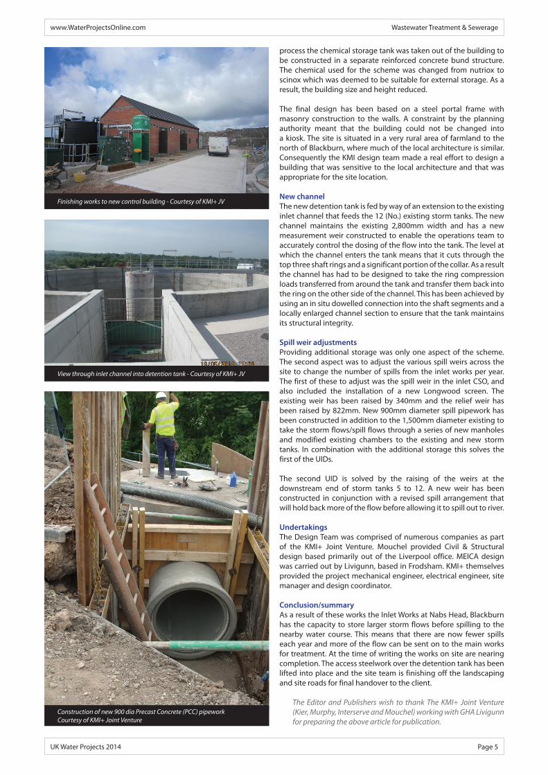
Spill weir adjustmentsProviding additional storage was only one aspect of the scheme. The second aspect was to adjust the various spill weirs across the site to change the number of spills from the inlet works per year. The first of these to adjust was the spill weir in the inlet CSO, and also included the installation of a new Longwood screen. The existing weir has been raised by 340mm and the relief weir has been raised by 822mm. New 900mm diameter spill pipework has been constructed in addition to the 1,500mm diameter existing to take the storm flows/spill flows through a series of new manholes and modified existing chambers to the existing and new storm tanks. In combination with the additional storage this solves the first of the UIDs.
The second UID is solved by the raising of the weirs at the downstream end of storm tanks 5 to 12. A new weir has been constructed in conjunction with a revised spill arrangement that will hold back more of the flow before allowing it to spill out to river.
UndertakingsThe Design Team was comprised of numerous companies as part of the KMI+ Joint Venture. Mouchel provided Civil & Structural design based primarily out of the Liverpool office. MEICA design was carried out by Livigunn, based in Frodsham. KMI+ themselves provided the project mechanical engineer, electrical engineer, site manager and design coordinator.
Conclusion/summaryAs a result of these works the Inlet Works at Nabs Head, Blackburn has the capacity to store larger storm flows before spilling to the nearby water course. This means that there are now fewer spills each year and more of the flow can be sent on to the main works for treatment. At the time of writing the works on site are nearing completion. The access steelwork over the detention tank has been lifted into place and the site team is finishing off the landscaping and site roads for final handover to the client.
The Editor and Publishers wish to thank The KMI+ Joint Venture (Kier, Murphy, Interserve and Mouchel) working with GHA Livigunn for preparing the above article for publication.
Finishing works to new control building - Courtesy of KMI+ JV
Construction of new 900 dia Precast Concrete (PCC) pipework Courtesy of KMI+ Joint Venture
View through inlet channel into detention tank - Courtesy of KMI+ JV
www.WaterProjectsOnline.com Wastewater Treatment & Sewerage
UK Water Projects 2014 Page 5