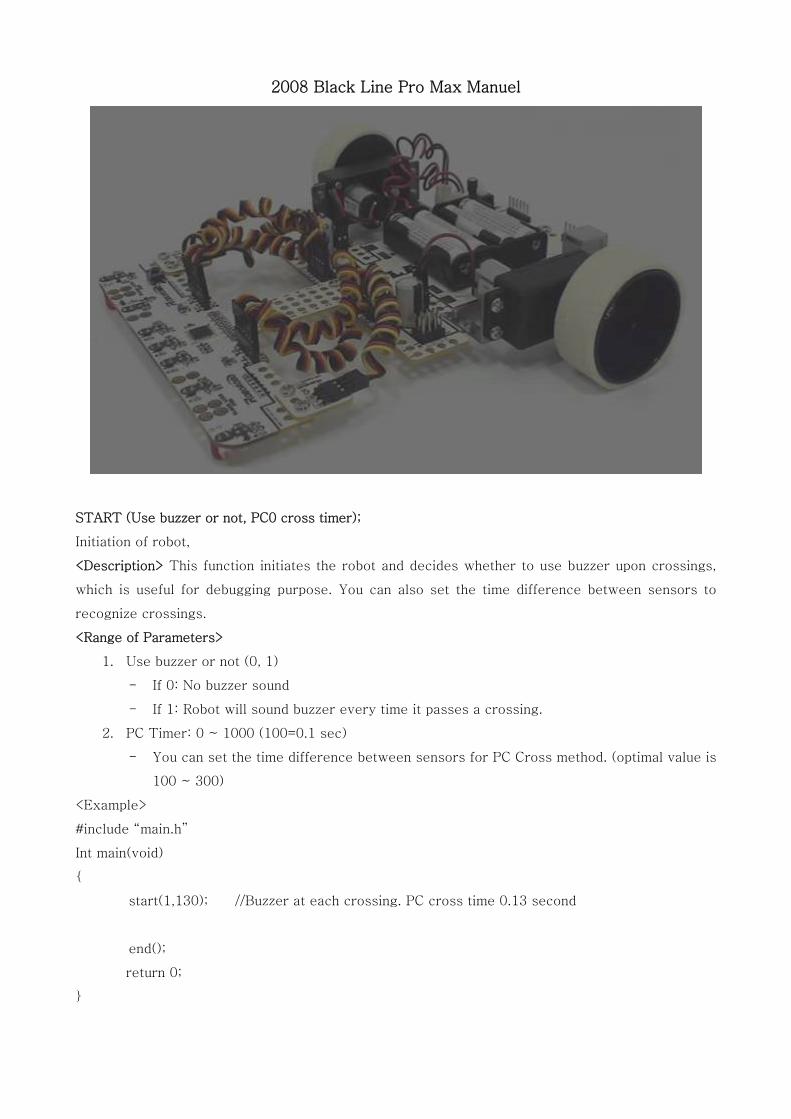
Black Line Pro Program 020808
24
2008 Black Line Pro Max Manuel START (Use buzzer or not, PC0 cross timer); Initiation of robot, <Description> This function initiates the robot and decides whether to use buzzer upon crossings, which is useful for debugging purpose. You can also set the time difference between sensors to recognize crossings. <Range of Parameters> 1. Use buzzer or not (0, 1) - If 0: No buzzer sound - If 1: Robot will sound buzzer every time it passes a crossing. 2. PC Timer: 0 ~ 1000 (100=0.1 sec) - You can set the time difference between sensors for PC Cross method. (optimal value is 100 ~ 300) <Example> #include “main.h” Int main(void) { start(1,130); //Buzzer at each crossing. PC cross time 0.13 second end(); return 0; }
-
Upload
drshahril-zulkarnain -
Category
Documents
-
view
384 -
download
13
description
this is for black line pro program
Transcript of Black Line Pro Program 020808
2008 Black Line Pro Max Manuel
START (Use buzzer or not, PC0 cross timer);
Initiation of robot,
<Description> This function initiates the robot and decides whether to use buzzer upon crossings,
which is useful for debugging purpose. You can also set the time difference between sensors to
recognize crossings.
<Range of Parameters>
1. Use buzzer or not (0, 1)
- If 0: No buzzer sound
- If 1: Robot will sound buzzer every time it passes a crossing.
2. PC Timer: 0 ~ 1000 (100=0.1 sec)
- You can set the time difference between sensors for PC Cross method. (optimal value is
100 ~ 300)
<Example>
#include “main.h”
Int main(void)
{
start(1,130); //Buzzer at each crossing. PC cross time 0.13 second
end();
return 0;
}
LINECOLOR (line color);
Setting the line color
<Description> It decides the color of line which robot will trace.
<Range of parameters>
1. line color: black, white
- black: Line is black
- white: Line is white
<Example>
#include “main.h”
Int main(void)
{
start(1,130); //Buzzer at each crossing. PC cross time 0.13 second
linecolor(black); //Set the color of line as black
end();
return 0;
}
SENSOR (direction of robot movement);
Selecting the direction of robot
<Description> You can set the direction of robot by choosing front or back 7-channel auto sensor.
If the robot is to trace line forward, the auto sensor needs to be put in front and the setting,
sensor(ff); If you put auto sensors both front and back, you can choose to go forward or
backward simply by changing sensor function.
<Range of parameters>
1. Direction of robot movement
- FF: Robot will trace line forward
- BB: Robot will trace line backward (Rear sensor has to be put.)
<Example>
#include “main.h”
Int main(void)
{
start(1,130); //Buzzer at each crossing. PC cross time 0.13 second
linecolor(black); //Set the color of line as black
sensor(ff); //Front sensor selected.
Line(pp,ff,20,0); //Tracing line forward
Sensor(bb); //Rear sensor selected.
Line(pp,ff,20,0); //Tracing line backward
end();
return 0;
}
ERROR (whether to use robot error function, robot error timer);
Robot stops operation in Error situation
<Description> Robot can be damaged if it goes out of line and its motor cannot turn. This is an
error situation and the motors need to be stopped quickly. If there is no change in sensor value for
the time set in the robot error timer, program will cease. Since wrong settings can cause
malfunction of robot, set appropriate value. After robot started, it will stop when pre-set error time
is exceeded.
<Range of parameters>
1. whether Error function will be set: 0,1
- 0: Error function is not used.
- 1: Error function is used
2. Robot error timer: 0 ~ 65000 (maximum 65 seconds)
- The program will stop if none of 7 sensors receive new input during the given time.
<Example>
#include “main.h”
Int main(void)
{
start(1,130); //Buzzer at each crossing. PC cross time 0.13 second
linecolor(black); //Set the color of line as black
sensor(ff); //Front sensor selected.
Error(1,500); //Error setting. Program will cease if there is no sensor input for 0.5 second
line(tt,fl,20,0); //Crossing 1
line(pp,ff,20,0); //Crossing 2
line(pp,ll,20,0); //Crossing 3
line(tt,rr,20,0); //Crossing 4
line(tt,rr,20,0); //Crossing 5
end();
return 0;
}
Under the program as above, it may happen that robot may run out of the line, let us say after
Crossing 2, and hit a wall or damage motors by applying continuous load. When Error function is set
with value 500, it will automatically stop after 0.5 seconds.
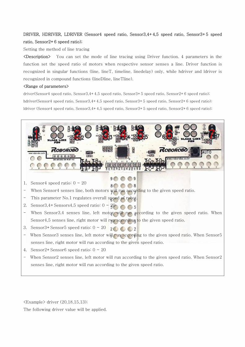
DRIVER, HDRIVER, LDRIVER (Sensor4 speed ratio, Sensor3,4+4,5 speed ratio, Sensor3+5 speed
ratio, Sensor2+6 speed ratio);
Setting the method of line tracing
<Description> You can set the mode of line tracing using Driver function. 4 parameters in the
function set the speed ratio of motors when respective sensor senses a line. Driver function is
recognized in singular functions (line, lineT, timeline, linedelay) only, while hdriver and ldriver is
recognized in compound functions (lineDline, lineTline).
<Range of parameters>
driver(Sensor4 speed ratio, Sensor3,4+4,5 speed ratio, Sensor3+5 speed ratio, Sensor2+6 speed ratio);
hdriver(Sensor4 speed ratio, Sensor3,4+4,5 speed ratio, Sensor3+5 speed ratio, Sensor2+6 speed ratio);
ldriver (Sensor4 speed ratio, Sensor3,4+4,5 speed ratio, Sensor3+5 speed ratio, Sensor2+6 speed ratio);
1. Sensor4 speed ratio: 0 ~ 20
- When Sensor4 senses line, both motors will run according to the given speed ratio.
- This parameter No.1 regulates overall speed of robot.
2. Sensor3,4+Sensors4,5 speed ratio: 0 ~ 20
- When Sensor3,4 senses line, left motor will run according to the given speed ratio. When
Sensor4,5 senses line, right motor will run according to the given speed ratio.
3. Sensor3+Sensor5 speed ratio: 0 ~ 20
- When Sensor3 senses line, left motor will run according to the given speed ratio. When Sensor5
senses line, right motor will run according to the given speed ratio.
4. Sensor2+Sensor6 speed ratio: 0 ~ 20
- When Sensor2 senses line, left motor will run according to the given speed ratio. When Sensor2
senses line, right motor will run according to the given speed ratio.
<Example> driver (20,18,15,13);
The following driver value will be applied.
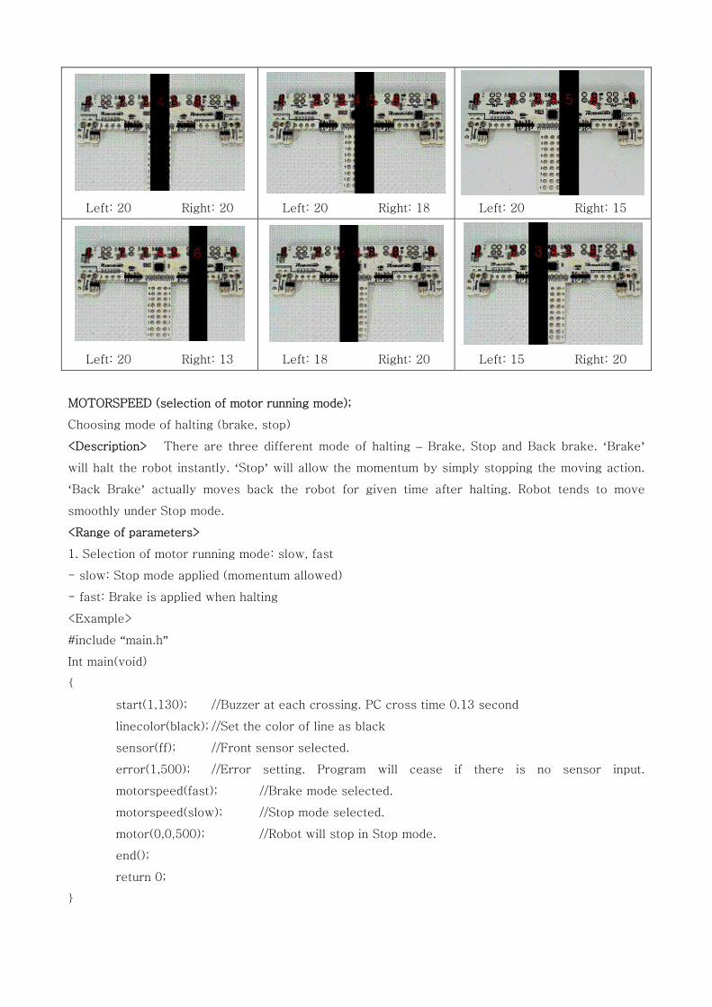
Left: 20 Right: 20
Left: 20 Right: 18 Left: 20 Right: 15
Left: 20 Right: 13
Left: 18 Right: 20
Left: 15 Right: 20
MOTORSPEED (selection of motor running mode);
Choosing mode of halting (brake, stop)
<Description> There are three different mode of halting – Brake, Stop and Back brake. ‘Brake’
will halt the robot instantly. ‘Stop’ will allow the momentum by simply stopping the moving action.
‘Back Brake’ actually moves back the robot for given time after halting. Robot tends to move
smoothly under Stop mode.
<Range of parameters>
1. Selection of motor running mode: slow, fast
- slow: Stop mode applied (momentum allowed)
- fast: Brake is applied when halting
<Example>
#include “main.h”
Int main(void)
{
start(1,130); //Buzzer at each crossing. PC cross time 0.13 second
linecolor(black); //Set the color of line as black
sensor(ff); //Front sensor selected.
error(1,500); //Error setting. Program will cease if there is no sensor input.
motorspeed(fast); //Brake mode selected.
motorspeed(slow); //Stop mode selected.
motor(0,0,500); //Robot will stop in Stop mode.
end();
return 0;
}
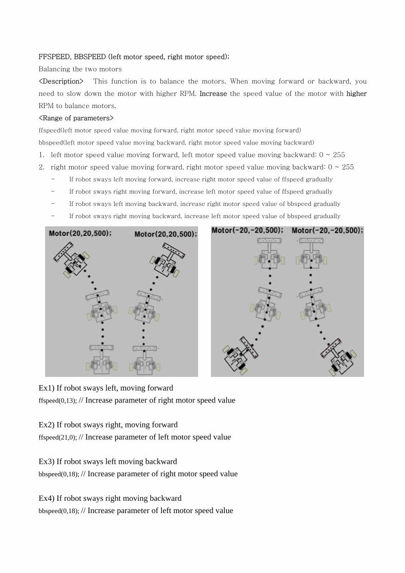
FFSPEED, BBSPEED (left motor speed, right motor speed);
Balancing the two motors
<Description> This function is to balance the motors. When moving forward or backward, you
need to slow down the motor with higher RPM. Increase the speed value of the motor with higher
RPM to balance motors.
<Range of parameters>
ffspeed(left motor speed value moving forward, right motor speed value moving forward)
bbspeed(left motor speed value moving backward, right motor speed value moving backward)
1. left motor speed value moving forward, left motor speed value moving backward: 0 ~ 255
2. right motor speed value moving forward, right motor speed value moving backward: 0 ~ 255
- If robot sways left moving forward, increase right motor speed value of ffspeed gradually
- If robot sways right moving forward, increase left motor speed value of ffspeed gradually
- If robot sways left moving backward, increase right motor speed value of bbspeed gradually
- If robot sways right moving backward, increase left motor speed value of bbspeed gradually
Ex1) If robot sways left, moving forward ffspeed(0,13); // Increase parameter of right motor speed value Ex2) If robot sways right, moving forward ffspeed(21,0); // Increase parameter of left motor speed value Ex3) If robot sways left moving backward bbspeed(0,18); // Increase parameter of right motor speed value
Ex4) If robot sways right moving backward bbspeed(0,18); // Increase parameter of left motor speed value
MOTOR (left motor speed, right motor speed, run time);
Driving motors
<Description> This function is used when driving the motors.
<Range of parameters>
1. Left motor speed: -20 ~ 20
2. Right motor speed: -20 ~ 20
3. Run time: 0 ~ 65000 (100=0.1 sec)
<Example>
#include “main.h”
Int main(void)
{
start(1,130); //Buzzer at each crossing. PC cross time 0.13 second
motor(20,20,500); //Robot will move forward for 0.5 second
motor(0,0,500); //Robot will stop for 0.5 second
motor(-20,-20,500); //Robot will move backward for 0.5 second
motor(0,0,500); //Robot will stop for 0.5 second
end();
return 0;
}
DELAY_MS (delay time);
Delay
<Description> It delays (maintains) action for the given time.
<Range of parameters>
1. Delay value: 0 ~ 65000 (100=0.1 sec)
-> 1 = 1 msec (0.001 sec)
-> 10 = 10 msec (0.01 sec)
-> 100 = 100 msec (0.1 sec)
-> 1000 = 1000 msec (1 sec)
<Example>
#include “main.h”
Int main(void)
{
start(1,130);
delay_ms(1) //Delay 0.001 second
delay_ms(1000) //Delay 1 second
end();
return 0;
}
LINE, LINET, TIMELINE(method of recognizing crossing, direction after recognizing crossing, moving
speed, back brake time, action time);
Basic functions of Line Tracer
<Description> As the most basic function, it recognizes crossing and sets moving direction, speed, etc.
There are total 7 methods of recognizing crossings, after which robot will turn to the direction given. Back
brake helps more precise actions. Timeline function is similar to Line function, except that robot starts moving
after the total action time is passed. Total action time is accumulated time starting from Start function. The
total action time in the Timeline function can be reset using Timer function.
In LineT function, robot moves for the given time only. If a cross is recognized during the given time, the time
will be disregarded and robot will stop.
<Range of parameters>
line (method of recognizing crossing, direction after recognizing crossing, moving speed, back brake time);
linet(method of recognizing crossing, direction after recognizing crossing, moving speed, back brake time,
action time);
timeline(method of recognizing crossing, direction after recognizing crossing, moving speed, back brake time,
total action time);
1. Method of recognizing crossing: PP cross (†, ㅜ), TT cross (ㅓ, ㅏ, Γ, ㄱ)
PP cross: PP0, PP1, PP2, PP3 (default PP = PP0)
PP cross recognizes crossing when cross line is present left and right (†, ㅜ)
PP0: when time difference between sensor1 and sensor7 is smaller than PC timer
PP1: when time difference between sensor1,2 and sensor6,7 is smaller than PC timer
PP2: when 5 or more sensors sense the line except Sensor4
PP3: when 6 or more sensors sense the line except Sensor4
TT cross: TT1, TT2, TT3 (default TT = TT2)
TT cross recognizes crossing when cross line is present either left or right (ㅓ, ㅏ, Γ, ㄱ)
TT1: when sensed by Sensor1 for FL, LL, SL and by Sensor7 for FR, RR, SR
TT2: when sensed by Sensor1,2 for FL, LL, SL and by Sensor6,7 for FR, RR, SR
TT3: when sensed by Sensor1,2,3 for FL, LL, SL and by Sensor5,6,7 for FR, RR, SR
2. Direction after recognizing crossing: PP cross (FF, LL, RR, SS) TT cross (FF, FL, FR, LL, RR, SL, SR)
- FF: Robot stops after passing cross lines
- FL: Robot stops after passing cross line on the left
- FR: Robot stops after passing cross line on the right
- LL: Robot turns left after passing cross line on the left
- RR: Robot turns right after passing cross line on the right
- SS: Robot stops upon sensing cross lines
- SL: Robot stops upon sensing cross line on the left
- SR: Robot stops upon sensing cross line on the right
3. Speed: 0 ~ 20
4. Back brake time: -30000 ~ 30000
- Positive value: Inverse electric pressure is applied after passing the crossing.
- Negative value: The robot continues tracing line for the given time. When turning left(LL)
or right(RR), negative value works as positive value. Robot moves forward straight, without
tracing line, for the given time in cases of SS, SL and SR.
5. LineT action time: 0 ~ 65000 (100=0.1sec)
- Robot traces line for the given time but stops when recognizes a crossing.
6. Timeline (total) action time: 0 ~ 65000 (100=0.1sec)
- Robot starts action after passing the time given (counting from Start)
<Example>
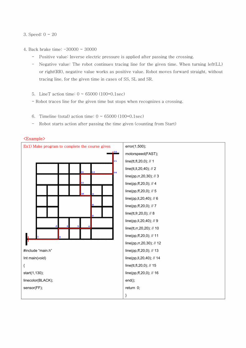
Ex1) Make program to complete the course given
#include “main.h”
Int main(void)
{
start(1,130);
linecolor(BLACK);
sensor(FF);
error(1,500);
motorspeed(FAST);
line(tt,fl,20,0); // 1
line(tt,ll,20,40); // 2
line(pp,rr,20,30); // 3
line(pp,ff,20,0); // 4
line(pp,ff,20,0); // 5
line(pp,ll,20,40); // 6
line(pp,ff,20,0); // 7
line(tt,fr,20,0); // 8
line(pp,ll,20,40); // 9
line(tt,rr,20,20); // 10
line(pp,ff,20,0); // 11
line(pp,rr,20,30); // 12
line(pp,ff,20,0); // 13
line(pp,ll,20,40); // 14
line(tt,fl,20,0); // 15
line(pp,ff,20,0); // 16
end();
return 0;
}
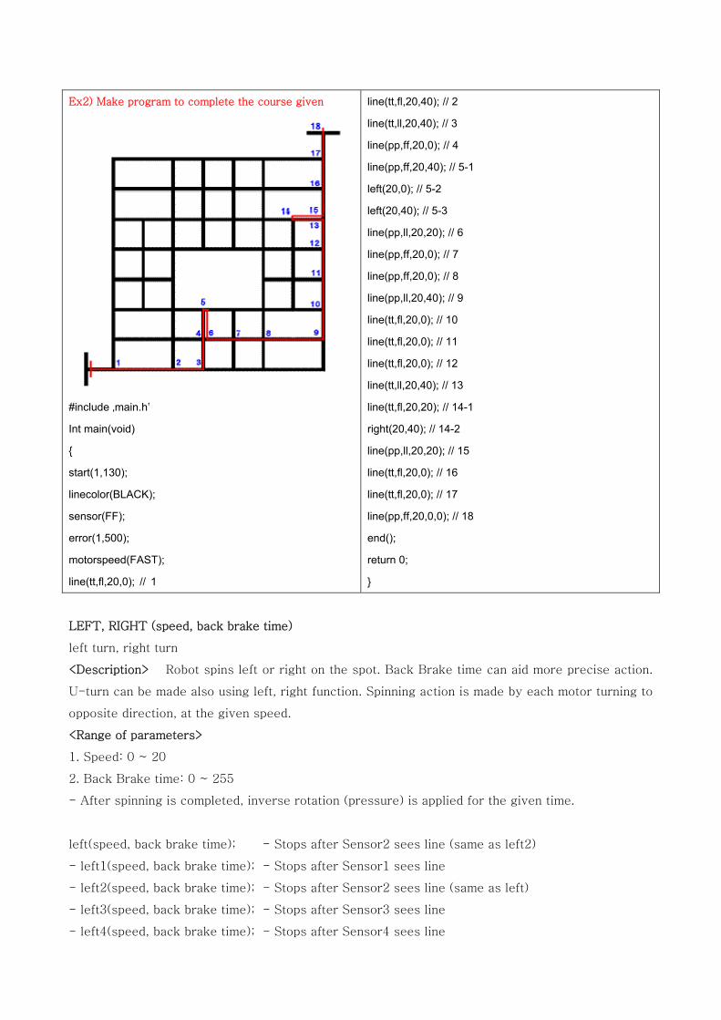
Ex2) Make program to complete the course given
#include ‚main.h‛
Int main(void)
{
start(1,130);
linecolor(BLACK);
sensor(FF);
error(1,500);
motorspeed(FAST);
line(tt,fl,20,0); // 1
line(tt,fl,20,40); // 2
line(tt,ll,20,40); // 3
line(pp,ff,20,0); // 4
line(pp,ff,20,40); // 5-1
left(20,0); // 5-2
left(20,40); // 5-3
line(pp,ll,20,20); // 6
line(pp,ff,20,0); // 7
line(pp,ff,20,0); // 8
line(pp,ll,20,40); // 9
line(tt,fl,20,0); // 10
line(tt,fl,20,0); // 11
line(tt,fl,20,0); // 12
line(tt,ll,20,40); // 13
line(tt,fl,20,20); // 14-1
right(20,40); // 14-2
line(pp,ll,20,20); // 15
line(tt,fl,20,0); // 16
line(tt,fl,20,0); // 17
line(pp,ff,20,0,0); // 18
end();
return 0;
}
LEFT, RIGHT (speed, back brake time)
left turn, right turn
<Description> Robot spins left or right on the spot. Back Brake time can aid more precise action.
U-turn can be made also using left, right function. Spinning action is made by each motor turning to
opposite direction, at the given speed.
<Range of parameters>
1. Speed: 0 ~ 20
2. Back Brake time: 0 ~ 255
- After spinning is completed, inverse rotation (pressure) is applied for the given time.
left(speed, back brake time); - Stops after Sensor2 sees line (same as left2)
- left1(speed, back brake time); - Stops after Sensor1 sees line
- left2(speed, back brake time); - Stops after Sensor2 sees line (same as left)
- left3(speed, back brake time); - Stops after Sensor3 sees line
- left4(speed, back brake time); - Stops after Sensor4 sees line
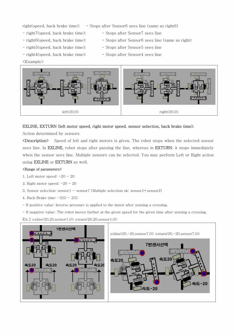
right(speed, back brake time); - Stops after Sensor6 sees line (same as right6)
- right7(speed, back brake time); - Stops after Sensor7 sees line
- right6(speed, back brake time); - Stops after Sensor6 sees line (same as right)
- right5(speed, back brake time); - Stops after Sensor5 sees line
- right4(speed, back brake time); - Stops after Sensor4 sees line
<Example>
left(20,0); right(20,0);
EXLINE, EXTURN (left motor speed, right motor speed, sensor selection, back brake time);
Action determined by sensors
<Description> Speed of left and right motors is given. The robot stops when the selected sensor
sees line. In EXLINE, robot stops after passing the line, whereas in EXTURN, it stops immediately
when the sensor sees line. Multiple sensors can be selected. You may perform Left or Right action
using EXLINE or EXTURN as well.
<Range of parameters>
1. Left motor speed: -20 ~ 20
2. Right motor speed: -20 ~ 20
3. Sensor selection: sensor1 ~ sensor7 (Multiple selection ok: sensor1+sensor2)
4. Back Brake time: -255 ~ 255
- If positive value: Inverse pressure is applied to the motor after sensing a crossing.
- If negative value: The robot moves further at the given speed for the given time after sensing a crossing.
Ex.1 exline(20,20,sensor1,0); exturn(20,20,sensor1,0);
exline(20,-20,sensor7,0); exturn(20,-20,sensor7,0);
Ex2) exline(20,10,sensor1+sensor7,0);
//Robot stops after sensors 1 and 7 see black line at the same time.
Ex3) exturn(20,20,sensor1+sensor2+sensor3+sensor4,0);
//Robot stops when sensors1,2,3,4 see black line at the same time.
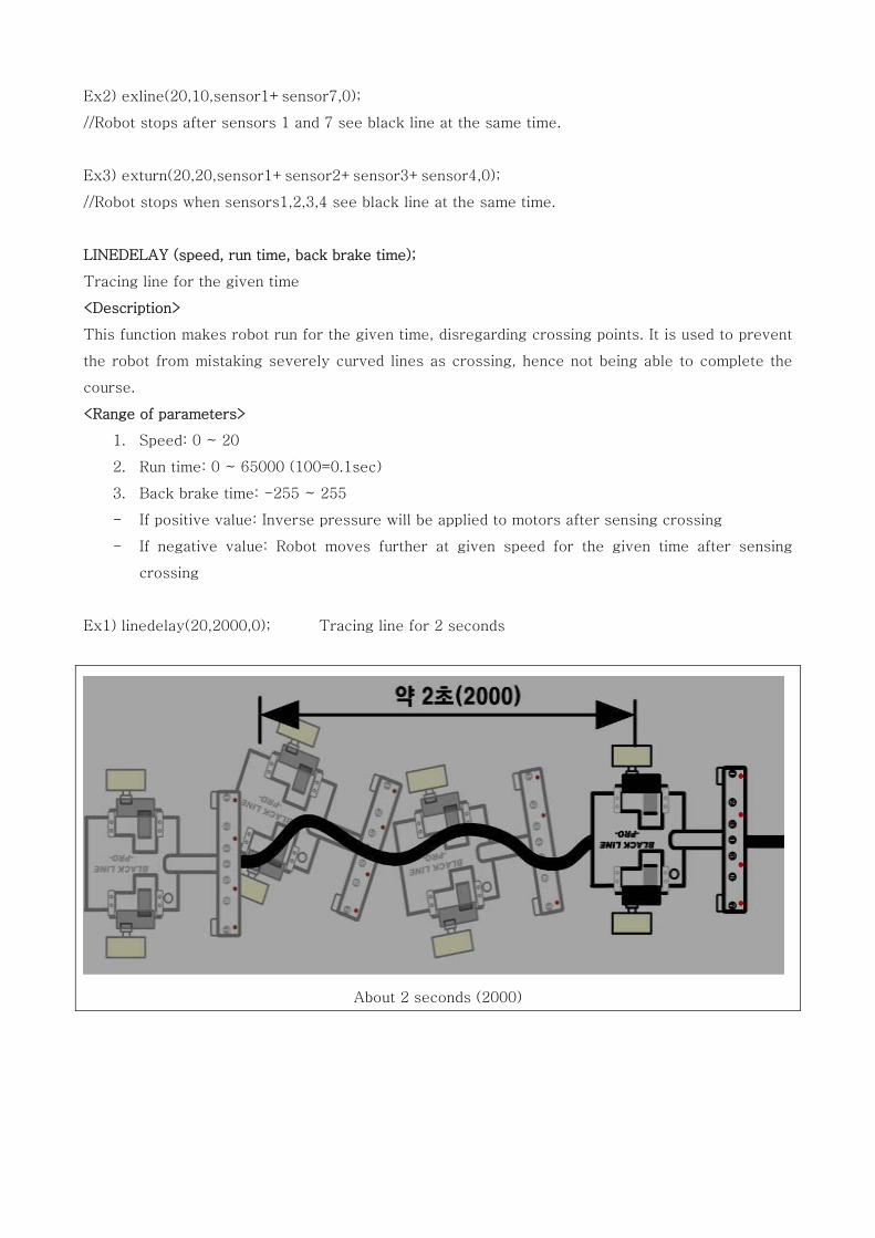
LINEDELAY (speed, run time, back brake time);
Tracing line for the given time
<Description>
This function makes robot run for the given time, disregarding crossing points. It is used to prevent
the robot from mistaking severely curved lines as crossing, hence not being able to complete the
course.
<Range of parameters>
1. Speed: 0 ~ 20
2. Run time: 0 ~ 65000 (100=0.1sec)
3. Back brake time: -255 ~ 255
- If positive value: Inverse pressure will be applied to motors after sensing crossing
- If negative value: Robot moves further at given speed for the given time after sensing
crossing
Ex1) linedelay(20,2000,0); Tracing line for 2 seconds
About 2 seconds (2000)
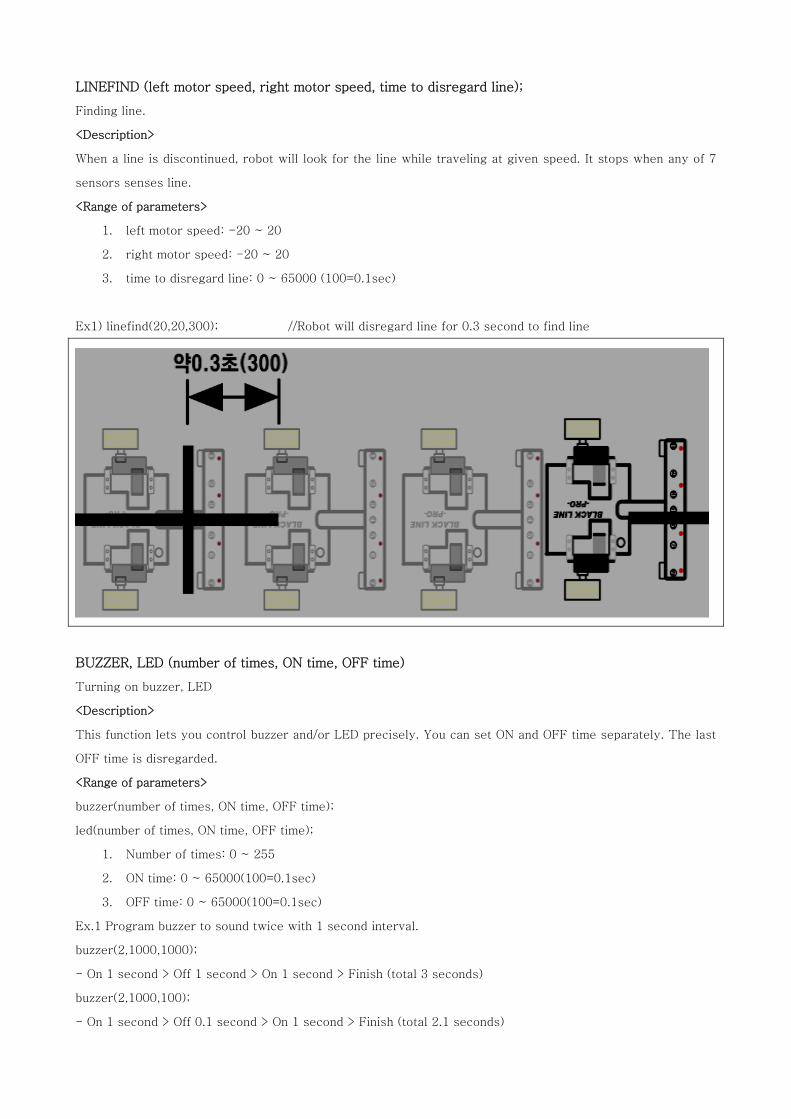
LINEFIND (left motor speed, right motor speed, time to disregard line);
Finding line.
<Description>
When a line is discontinued, robot will look for the line while traveling at given speed. It stops when any of 7
sensors senses line.
<Range of parameters>
1. left motor speed: -20 ~ 20
2. right motor speed: -20 ~ 20
3. time to disregard line: 0 ~ 65000 (100=0.1sec)
Ex1) linefind(20,20,300); //Robot will disregard line for 0.3 second to find line
BUZZER, LED (number of times, ON time, OFF time)
Turning on buzzer, LED
<Description>
This function lets you control buzzer and/or LED precisely. You can set ON and OFF time separately. The last
OFF time is disregarded.
<Range of parameters>
buzzer(number of times, ON time, OFF time);
led(number of times, ON time, OFF time);
1. Number of times: 0 ~ 255
2. ON time: 0 ~ 65000(100=0.1sec)
3. OFF time: 0 ~ 65000(100=0.1sec)
Ex.1 Program buzzer to sound twice with 1 second interval.
buzzer(2,1000,1000);
- On 1 second > Off 1 second > On 1 second > Finish (total 3 seconds)
buzzer(2,1000,100);
- On 1 second > Off 0.1 second > On 1 second > Finish (total 2.1 seconds)
Ex.2 Turn on the LED 3 times at 0.5 second interval
led(3,500,500);
- On 0.5 second > Off 0.5 second > On 0.5 second > Off 0.5 second > On 0.5 second > Finish (total 2.5 seconds)
led(3,500,100);
- On 0.5 second > Off 0.1 second > On 0.5 second > Off 0.1 second > On 0.5 second > Finish (total 1.7 seconds)
BUZZERLED (use buzzer?, use LED?, Number of times, Interval);
Turning on buzzer and LED at the same time
<Description>
The function is used when you control buzzer and LED at the same time. The number of times and
interval can be set. The last Off time is disregarded.
Range of parameters
1. Use buzzer or not: 0, 1
- 0: Not using buzzer
- 1: Using buzzer
2. Use LED or not: 0, 1
- 0: Not using LED
- 1: Using LED
3. Number of times: 0 ~ 255
4. Operation interval: 0 ~ 65000 (100=0.1 sec)
Examples
Ex.1 Turn on buzzer and LED twice at the same time at 1 second interval.
buzzerled(1,1,2,1000);
- On 1 second > Off 1 second > On 1 second > Finish (total 3 seconds)
Ex.2 Turn on buzzer only, twice at 1 second interval
buzzerled(1,0,2,1000);
- On 1 second > Off 1 second > On 1 second > Finish (total 3 seconds)
Ex.3 Turn on LED only twice at 1 second interval
buzzerled(0,1,2,1000);
- On 1 second > Off 1 second > On 1 second > Finish (total 3 seconds)
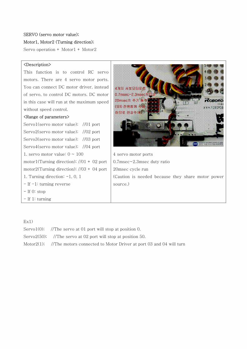
SERVO (servo motor value);
Motor1, Motor2 (Turning direction);
Servo operation + Motor1 + Motor2
<Description>
This function is to control RC servo
motors. There are 4 servo motor ports.
You can connect DC motor driver, instead
of servo, to control DC motors. DC motor
in this case will run at the maximum speed
without speed control.
<Range of parameters>
Servo1(servo motor value); //01 port
Servo2(servo motor value); //02 port
Servo3(servo motor value); //03 port
Servo4(servo motor value); //04 port
1. servo motor value: 0 ~ 100
motor1(Turning direction); //01 + 02 port
motor2(Turning direction); //03 + 04 port
1. Turning direction: -1, 0, 1
- If -1: turning reverse
- If 0: stop
- If 1: turning
4 servo motor ports
0.7msec~2.3msec duty ratio
20msec cycle run
(Caution is needed because they share motor power
source.)
Ex1)
Servo1(0); //The servo at 01 port will stop at position 0.
Servo2(50); //The servo at 02 port will stop at position 50.
Motor2(1); //The motors connected to Motor Driver at port 03 and 04 will turn
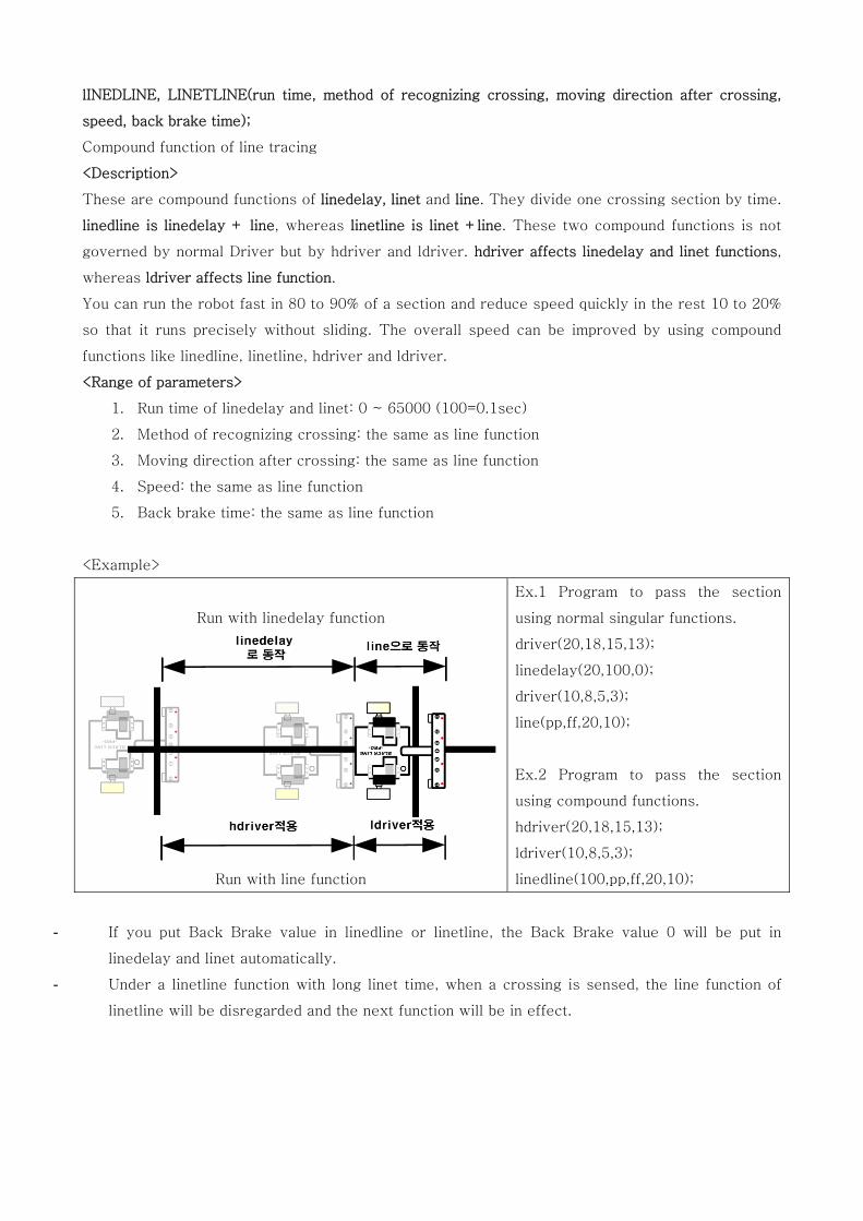
lINEDLINE, LINETLINE(run time, method of recognizing crossing, moving direction after crossing,
speed, back brake time);
Compound function of line tracing
<Description>
These are compound functions of linedelay, linet and line. They divide one crossing section by time.
linedline is linedelay + line, whereas linetline is linet +line. These two compound functions is not
governed by normal Driver but by hdriver and ldriver. hdriver affects linedelay and linet functions,
whereas ldriver affects line function.
You can run the robot fast in 80 to 90% of a section and reduce speed quickly in the rest 10 to 20%
so that it runs precisely without sliding. The overall speed can be improved by using compound
functions like linedline, linetline, hdriver and ldriver.
<Range of parameters>
1. Run time of linedelay and linet: 0 ~ 65000 (100=0.1sec)
2. Method of recognizing crossing: the same as line function
3. Moving direction after crossing: the same as line function
4. Speed: the same as line function
5. Back brake time: the same as line function
<Example>
Run with linedelay function
Run with line function
Ex.1 Program to pass the section
using normal singular functions.
driver(20,18,15,13);
linedelay(20,100,0);
driver(10,8,5,3);
line(pp,ff,20,10);
Ex.2 Program to pass the section
using compound functions.
hdriver(20,18,15,13);
ldriver(10,8,5,3);
linedline(100,pp,ff,20,10);
- If you put Back Brake value in linedline or linetline, the Back Brake value 0 will be put in
linedelay and linet automatically.
- Under a linetline function with long linet time, when a crossing is sensed, the line function of
linetline will be disregarded and the next function will be in effect.
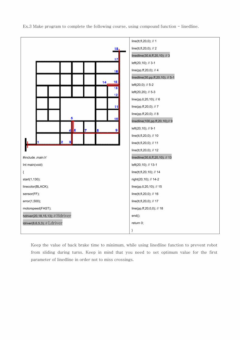
Ex.3 Make program to complete the following course, using compound function - linedline.
#include ‚main.h‛
Int main(void)
{
start(1,130);
linecolor(BLACK);
sensor(FF);
error(1,500);
motorspeed(FAST);
hdriver(20,18,15,13); // Hdriver
ldriver(8,6,5,3); // Ldriver
line(tt,fl,20,0); // 1
line(tt,fl,20,0); // 2
linedline(30,tt,ff,20,10); // 3
left(20,10); // 3-1
line(pp,ff,20,0); // 4
linedline(30,pp,ff,20,10); // 5-1
left(20,0); // 5-2
left(20,20); // 5-3
line(pp,ll,20,10); // 6
line(pp,ff,20,0); // 7
line(pp,ff,20,0); // 8
linedline(100,pp,ff,20,10);// 9
left(20,10); // 9-1
line(tt,fl,20,0); // 10
line(tt,fl,20,0); // 11
line(tt,fl,20,0); // 12
linedline(30,tt,ff,20,10); // 13
left(20,10); // 13-1
line(tt,fl,20,10); // 14
right(20,10); // 14-2
line(pp,ll,20,10); // 15
line(tt,fl,20,0); // 16
line(tt,fl,20,0); // 17
line(pp,ff,20,0,0); // 18
end();
return 0;
}
Keep the value of back brake time to minimum, while using linedline function to prevent robot
from sliding during turns. Keep in mind that you need to set optimum value for the first
parameter of linedline in order not to miss crossings.
SLINE (sensor selection, speed, back brake time);
A crossing is recognized when the selected sensor sees a line.
<Description>
You can select sensors to recognize crossings. Use sline function with care since it will stop the
robot immediately when the selected sensor sees a line.
<Range of parameters>
1. Selection of sensor(s): sensor1 ~ sensor7
2. Speed: 0 ~ 20
3. Back brake time: -255 ~ 255
- If positive value: Inverse pressure will be applied to motors upon recognizing crossing.
- If positive value: The robot will continue to move for the given time at the motor speed after
recognizing crossing.
<Example>
Ex1) sline(sensor1,20,0); //Robot will trace line at speed 20 until sensor1 sees line and stops.
Ex2) sline(sensor1+sensor2,20,0);
// Robot will trace line at speed 20 until sensor1 and sensor2 see line and stop.
Ex3) sline(sensor1+sensor2+sensor3,20,0);
// Robot will trace line at speed 20 until sensor1, sensor2 and sensor3 see line and stop.
TIMER, PCTIMER(timer value);
Setting timer
<Description>
You can reset time or initiate timeline function and adjust time difference value in PC cross.
<Range of parameters>
timer(timer value);
1. Timer value: 0 ~ 65000
- You can reset time or initiate timeline function.
pctimer(timer value);
1. Timer value: 0 ~ 65000
- You can adjust time difference value in PC cross.
<Example>
start(1,130);
timeline(pp,ff,20,0,10000); //Robot starts moving 10 seconds after Start function.
timeline(tt,rr,20,40,60000); // Robot starts moving 60 seconds after Start function.
timer(0); // Clearing time setting of timeline
timeline(tt,rr,20,40,10000); // Robot starts moving 10 seconds after timer function.
timeline(pp,rr,20,30,30000); // Robot starts moving 30 seconds after timer function.
SAVETIME (method of keeping time);
READTIME (function counter);
Measuring operation time of functions
<Description>
You can measure time taken to perform functions. Accumulative time and relative time can be
measured. When you choose accumulative time, the time from Start to End function will be
measured whereas, when you choose relative time, individual active time will be measured. The
records will be stored in EEPROM memory, which can be read through AVRISP window of AVR
Studio. You can use readtime function to check time while robot is in operation. You need to set
savetime function first in order to use readtime function.
<Range of parameters>
savetime(method of keeping time);
- If 0: The function is not in use.
- If 1: Accumulative time is set.
- If 2: Relative time is set.
readtime(function counter)
- Function counter: 1 ~ 99 (Time will be measured up to the current accumulative function counter.)
- Put the function number in function counter to read respective time.
- If(readtime(10)<10000 ->The accumulative or relative time until Function 10 will be
compared to 10 seconds.
<Example>
Ex.1 Measure action time for total 10 functions (accumulative time)
start(1,130);
savetime(1); // Accumulative time is set.
line(pp,ff,20,10); //function 1
left(20,20); //function 2
line(tt,ll,20,0); //function 3
linedelay(20,300,0); //function 4
line(tt,rr,20,0); //function 5
buzzer(2,100,100); //function 6
line(pp,ff,20,0); //function 7
line(pp,ff,20,0); //function 8
line(pp,rr,20,20); //function 9
line(tt,fr,20,0); //function 10
end();
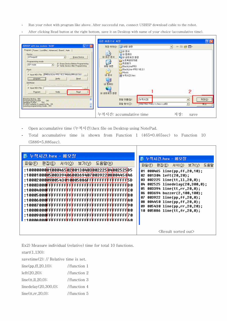
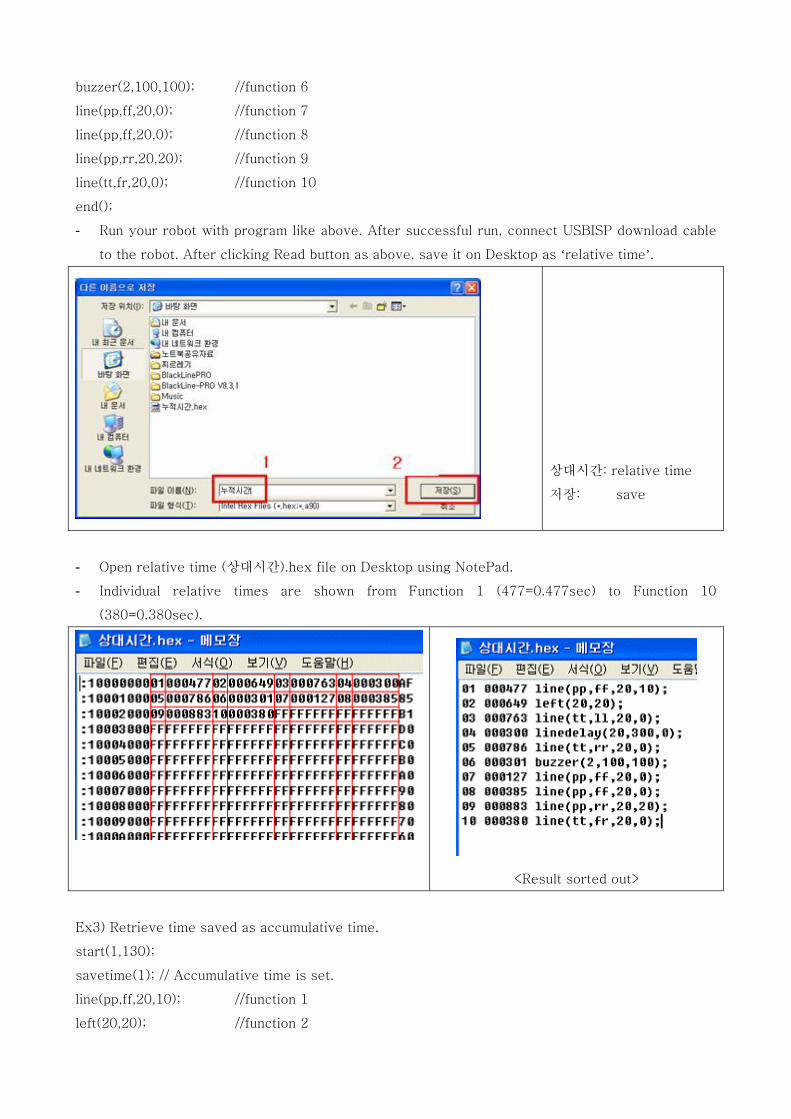
- Run your robot with program like above. After successful run, connect USBISP download cable to the robot.
- After clicking Read button at the right bottom, save it on Desktop with name of your choice (accumulative time).
누적시간: accumulative time 저장: save
- Open accumulative time (누적시간).hex file on Desktop using NotePad.
- Total accumulative time is shown from Function 1 (465=0.465sec) to Function 10
(5886=5.886sec).
<Result sorted out>
Ex2) Measure individual (relative) time for total 10 functions.
start(1,130);
savetime(2); // Relative time is set.
line(pp,ff,20,10); //function 1
left(20,20); //function 2
line(tt,ll,20,0); //function 3
linedelay(20,300,0); //function 4
line(tt,rr,20,0); //function 5
buzzer(2,100,100); //function 6
line(pp,ff,20,0); //function 7
line(pp,ff,20,0); //function 8
line(pp,rr,20,20); //function 9
line(tt,fr,20,0); //function 10
end();
- Run your robot with program like above. After successful run, connect USBISP download cable
to the robot. After clicking Read button as above, save it on Desktop as ‘relative time’.
상대시간: relative time
저장: save
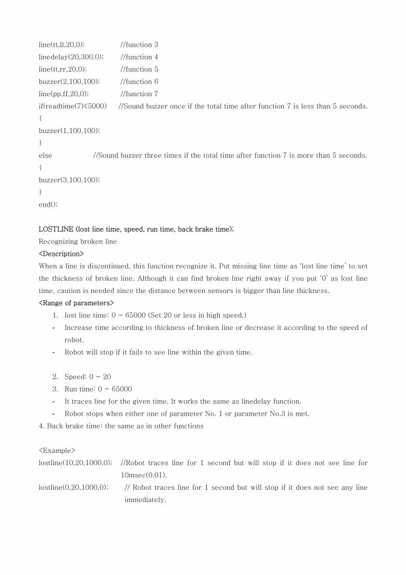
- Open relative time (상대시간).hex file on Desktop using NotePad.
- Individual relative times are shown from Function 1 (477=0.477sec) to Function 10
(380=0.380sec).
<Result sorted out>
Ex3) Retrieve time saved as accumulative time.
start(1,130);
savetime(1); // Accumulative time is set.
line(pp,ff,20,10); //function 1
left(20,20); //function 2
line(tt,ll,20,0); //function 3
linedelay(20,300,0); //function 4
line(tt,rr,20,0); //function 5
buzzer(2,100,100); //function 6
line(pp,ff,20,0); //function 7
if(readtime(7)<5000) //Sound buzzer once if the total time after function 7 is less than 5 seconds.
{
buzzer(1,100,100);
}
else //Sound buzzer three times if the total time after function 7 is more than 5 seconds.
{
buzzer(3,100,100);
}
end();
LOSTLINE (lost line time, speed, run time, back brake time);
Recognizing broken line
<Description>
When a line is discontinued, this function recognize it. Put missing line time as ‘lost line time’ to set
the thickness of broken line. Although it can find broken line right away if you put ‘0’ as lost line
time, caution is needed since the distance between sensors is bigger than line thickness.
<Range of parameters>
1. lost line time: 0 ~ 65000 (Set 20 or less in high speed.)
- Increase time according to thickness of broken line or decrease it according to the speed of
robot.
- Robot will stop if it fails to see line within the given time.
2. Speed: 0 ~ 20
3. Run time: 0 ~ 65000
- It traces line for the given time. It works the same as linedelay function.
- Robot stops when either one of parameter No. 1 or parameter No.3 is met.
4. Back brake time: the same as in other functions
<Example>
lostline(10,20,1000,0); //Robot traces line for 1 second but will stop if it does not see line for
10msec(0.01).
lostline(0,20,1000,0); // Robot traces line for 1 second but will stop if it does not see any line
immediately.
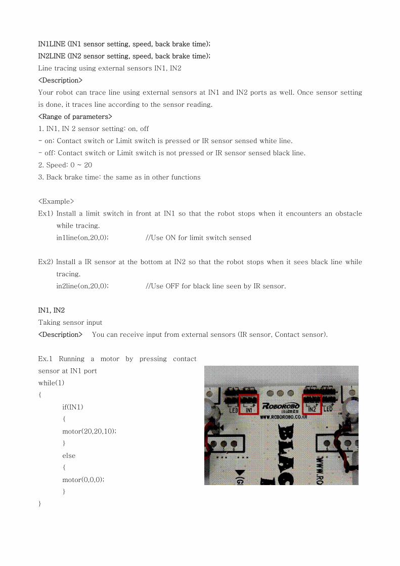
IN1LINE (IN1 sensor setting, speed, back brake time);
IN2LINE (IN2 sensor setting, speed, back brake time);
Line tracing using external sensors IN1, IN2
<Description>
Your robot can trace line using external sensors at IN1 and IN2 ports as well. Once sensor setting
is done, it traces line according to the sensor reading.
<Range of parameters>
1. IN1, IN 2 sensor setting: on, off
- on: Contact switch or Limit switch is pressed or IR sensor sensed white line.
- off: Contact switch or Limit switch is not pressed or IR sensor sensed black line.
2. Speed: 0 ~ 20
3. Back brake time: the same as in other functions
<Example>
Ex1) Install a limit switch in front at IN1 so that the robot stops when it encounters an obstacle
while tracing.
in1line(on,20,0); //Use ON for limit switch sensed
Ex2) Install a IR sensor at the bottom at IN2 so that the robot stops when it sees black line while
tracing.
in2line(on,20,0); //Use OFF for black line seen by IR sensor.
IN1, IN2
Taking sensor input
<Description> You can receive input from external sensors (IR sensor, Contact sensor).
Ex.1 Running a motor by pressing contact
sensor at IN1 port
while(1)
{
if(IN1)
{
motor(20,20,10);
}
else
{
motor(0,0,0);
}
}
Ex.2 Running motor when both IN1 and IN2 are pressed at the same time
while(1)
{
if(IN1&&IN2)
{
motor(20,20,10);
}
else
{
motor(0,0,0);
}
}
Ex.3 Running motor when either IN1 or IN2 is pressed.
while(1)
{
if(IN1 II IN2)
{
motor(20,20,10);
}
else
{
motor(0,0,0);
}
}
Ex4) Making motor run when IN1 is not pressed and making it stop when IN1 is pressed
while(1)
{
if(IN1==0)
{
motor(20,20,10);
}
else
{
motor(0,0,0);
}
}