(BK Trade Ticket Dispenser Logo) - Bingo King manual.pdf · (BK Trade Ticket Dispenser Logo) ......
36
www.bingoking.com Operators Manual
Transcript of (BK Trade Ticket Dispenser Logo) - Bingo King manual.pdf · (BK Trade Ticket Dispenser Logo) ......

(BK Trade Bingo Console) (BK Trade Bingo Console) (BK Trade Bingo Tabletop Console)
(BK Trade Ticket Dispenser Logo)
www.bingoking.comOperators Manual
Emerald Bingo Console
Operator’s Manual
Bingo King Co.2807 Lincoln Way
Lynnwood, WA 98087Phone 425-745-3700
Version 1.0January, 2007
Version 1.2January 2007
©2007 Bingo King Co. All Rights Reserved.
Bingo King Co.2807 Lincoln Way
Lynnwood, WA 98087phone: 425.745.3700
1. Unpacking .................................................................................... 1 Flashboard........................................................................................................................2 Console.............................................................................................................................3 BingoBalls........................................................................................................................4 WarrantyAssurance........................................................................................................4
2. Installation ...................................................................................5 ConsoleInstallation........................................................................................................5 FlashboardConnection/Installation............................................................................6
3. Controls ........................................................................................8 BasicControls..................................................................................................................8 GamePatternControls..................................................................................................9 ConsoleDisplayControls..............................................................................................9 FlashboardControls.....................................................................................................10
4. Game Pattern Programming and Recall .................................... 11 ProgrammingYourEmeraldBingoConsole............................................................11 RecallingPatternsOnYourEmeraldBingoConsole..............................................11 PatternProgrammingWorksheet................................................................................12
5. Operation ................................................................................... 13 PlayingAGame.............................................................................................................13
6. Customer Servicing .................................................................... 14 Cleaning..........................................................................................................................14 ConsoleLaminated&PaintedSurfaces...............................................................14 Console&FlashboardAcrylicSurfaces..............................................................14 BingoBalls................................................................................................................14 StaticTreatment.............................................................................................................15 ChangingLightBulbs...................................................................................................15 MixingChamberLightBulb..................................................................................15 Accessing4”FlashboardLamps...........................................................................16 Accessing8”FlashboardLamps...........................................................................17 ChangingFlashboardLightBulbs........................................................................18 Blower&MixerMaintenance......................................................................................19 ConsoleAirFilterReplacement..................................................................................20 FuseReplacement..........................................................................................................21
Table of Contents

7. Troubleshooting .........................................................................22 BlowerMotorTroubleshooting..................................................................................22 BlowerStoppedWorking.......................................................................................22 BlowerOperatesSlowly.........................................................................................22 MixerMotorTroubleshooting.....................................................................................23 MixerMotorStoppedWorking.............................................................................23 MixerMotorRunningSlow...................................................................................23 FlashboardOutputProblems......................................................................................23 FlashboardLightsFlicker.......................................................................................23 NoFlashboardResponse.......................................................................................23
8. Wiring Diagrams & PCB Layouts .............................................24 ConsoleWiring..............................................................................................................24 ConsoleSwitchWiring.................................................................................................25 ConsoleAXPCBRibbonCableConnections.........................................................26 AXandNVPCBLayout.............................................................................................27 AT(Timer)PCBLayout...............................................................................................28 BK3BCPCBLayout.....................................................................................................29
9. Warranty .....................................................................................30
�
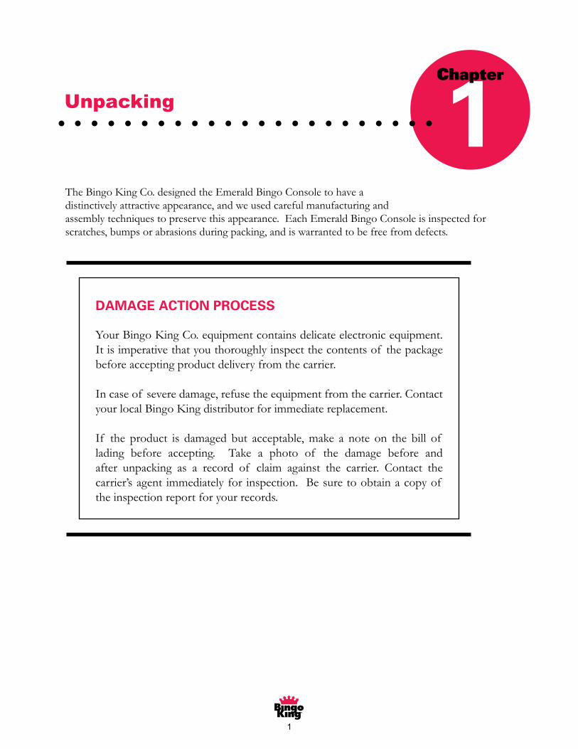
DAMAGE ACTION PROCESS
YourBingoKingCo.equipmentcontainsdelicateelectronicequipment.Itisimperativethatyouthoroughlyinspectthecontentsof thepackagebeforeacceptingproductdeliveryfromthecarrier.
Incaseof severedamage,refusetheequipmentfromthecarrier.ContactyourlocalBingoKingdistributorforimmediatereplacement.
If the product is damaged but acceptable, make a note on the bill of lading before accepting. Take a photo of the damage before andafter unpacking as a record of claim against the carrier. Contact thecarrier’sagent immediatelyfor inspection.Besuretoobtainacopyof theinspectionreportforyourrecords.
TheBingoKingCo.designedtheEmeraldBingoConsoletohaveadistinctivelyattractiveappearance,andweusedcarefulmanufacturingandassemblytechniquestopreservethisappearance.EachEmeraldBingoConsoleisinspectedforscratches,bumpsorabrasionsduringpacking,andiswarrantedtobefreefromdefects.
Unpacking 1Chapter
�
E M E R A L D B I N G O C O N S O L E
2
CAUTION:
Please take great care when unpacking the console and flashboard from the packingmaterial. Cutting the packing material too aggressively may lead to console or flashboarddamage.
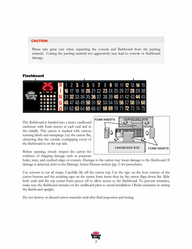
Flashboard
The flashboard is banded into a heavy cardboardenclosure with foam inserts at each end and inthe middle. This carton is marked with variouswarning labels and stampings. Lay the carton flat,observing that the outside overlapping cover ofthe flashboard is on the top side.
Before opening, closely inspect the carton forevidence of shipping damage such as punctureholes, tears, and crushed edges or corners. Damage to the carton may mean damage to the flashboard. Ifdamage is detected, refer to the Damage Action Process section (pg. 1) for procedures.
Use scissors to cut all straps. Carefully lift off the carton top. Cut the tape on the four corners of thecarton bottom and the retaining tape on the center foam insert then lay the carton flaps down flat. Slideboth ends and the top center foam pieces off to allow access to the flashboard. To prevent scratches,make sure the flashboard remains on the cardboard prior to actual installation. Obtain assistance in settingthe flashboard upright.
Do not destroy or discard carton materials until after final inspection and testing.

�
E M E R A L D B I N G O C O N S O L E
3
Console
The Emerald bingo console is packedwith foam protectors in a cardboard cartonand is skid-mounted. Once again, check thecarton for possible signs of damage. If damageis detected, refer to the Damage ActionProcess section (pg. 1) for procedures.
CAUTION:
The console weighs approximately 170 pounds. Please obtain help before lifting. Aminimum of two individuals is required for proper unpacking.
Use scissors to cut the straps from the skid only, taking care not to cut the straps protecting the console.With the help of at least one assistant, carefully lift the console from the skid and place it on solid flooring.Cut the remaining four straps from the console and remove the cardboard top.
Remove the two foam protectors inside the top and slide the cardboard tube up and off the console. Aminimum of two people are required to safely unpack the console. With one person lifting from the topof the ball-blower end and another individual grasping the two handles on the opposite end, raise theconsole up and out from the carton and foam inserts. Check that all casters are in place. Set unpackedconsole on solid flooring. Do not destroy or discard carton material until after final inspection and testing.
At this point you should inspect the console for shipping damage. All acrylic panels should be in place.Metal panels and their associated switches and parts should be operational. If problems are found in anyof these areas, immediately contact your distributor for advice and refer to the Damage Action Processsection (pg. 1) for procedures.
TheEmeraldBingoConsoleispackedwithfoamprotectorsinacardboardcartonandisskid-mounted.Onceagain,checkthecartonforpossiblesignsof damage.If damageisdetected,refertotheDamageActionProcesssection(pg.1)forprocedures.
Use scissors to cut the straps from the skidonly, taking carenot to cut the strapsprotecting theconsole.Withthehelpof atleastoneassistant,carefullylifttheconsolefromtheskidandplaceitonsolid flooring. Cut the remaining four straps from the console and remove the cardboard top.
Removethetwofoamprotectorsinsidethetopandslidethecardboardtubeupandoff theconsole.Aminimumof twopeoplearerequiredtosafelyunpacktheconsole.Lifttheconsoleupandoutfromthe carton and foam inserts. Check that all casters are in place. Set unpacked console on solid flooring. Do not destroy or discard carton material until after final inspection and testing.
Atthispointyoushouldinspecttheconsoleforshippingdamage.Allacrylicpanelsshouldbeinplace.Metalpanelsandtheirassociatedswitchesandpartsshouldbeoperational.If problemsarefoundinanyof theseareas,immediatelycontactyourdistributorforadviceandrefertotheDamageActionProcesssection(pg.1)forprocedures.
Console

�
866.405.3482 • www.bingoking.com
TECHNICAL ASSISTANCE CENTER
Support Hours: 8:00 AM to 12:00 AM EST
Providing Proactive SolutionsThrough Quality Service and Suppor t
Opentheboxof bingoballs,checkeachballfordamageandinserteachball into its corresponding slot in the console ball tray. If a ball has a flat spot,immerseitinhotwaterforashortperiodof timeanditshould“pop”backintoposition.If itdoesnot“pop”backintoshape,pleasecontactyourdistributorforareplacement.
Warranty Assurance
Youmustkeepacopyof yourreceiptorinvoiceforproof of purchase.Pleasereviewthewarrantyinformationonpage30of thismanual.
If thereareanyquestions,contactyourdistributororcallTechnicalAssistanceat:
866-405-3482
Bingo Balls
�
E M E R A L D B I N G O C O N S O L E
5
Installation
Console Installation
Plug the bingo console and flashboard (s) into any110/120 VAC 60HZ grounded power outlet.
CAUTION:
Consoles and flashboards can draw a considerable amount of current. Be aware of howmuch current is on one circuit breaker.
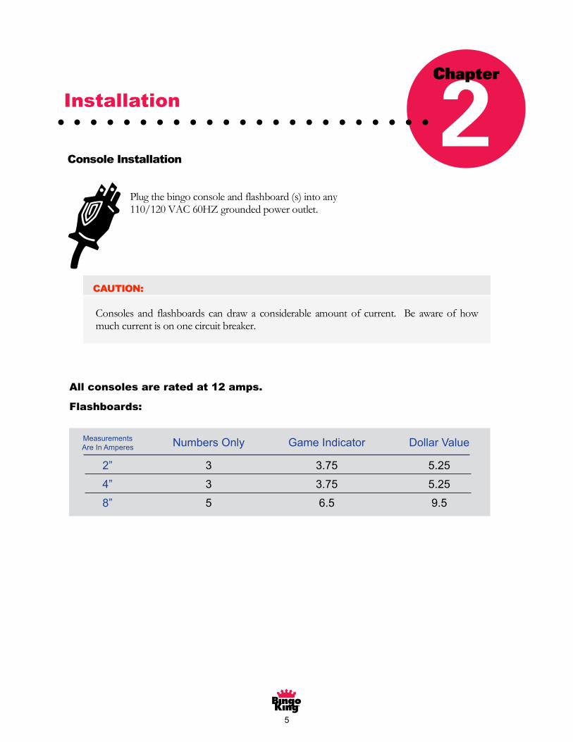
All consoles are rated at 12 amps.
Flashboards:
Measurements are in
AmperesNumbers Only Game Indicator Dollar Value
2” 3 3.75 5.25
4” 3 3.75 5.25
8” 5 6.5 9.5
12” 9.5 11.5 12
Chapter
2
NumbersOnly GameIndicator DollarValue
�” � �.7� �.��
�” � �.7� �.��
8” � 6.� 9.�
MeasurementsAreInAmperes
Installation 2Chapter
All consoles are rated at 12 amps.
Flashboards:
6
E M E R A L D B I N G O C O N S O L E
6
Flashboard Connection / Installation
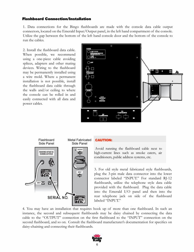
1. Data connections for the Bingo flashboards are made with the console data cable output connectors,located on the Emerald Input/Output panel, in the left hand compartment of the console. Permanentinstallations use the 3” access hole under the I/O panel to run the cables. Temporary installations utilizethe gap between the bottom of the lefthand console door and the bottom ofthe console to run the cables.
2. Install the flashboard data cable.When possible, we recommend using aone-piece cable avoiding splices,adapters and other mating devices.Wiring to the flashboard may bepermanently installed using a wiremold. Where a permanent installationis not possible, install the flashboarddata cable through the walls and/orceiling to where the console can berolled in and easily connected with alldata and power cables.
CAUTION:
Avoid running the flashboard cable next tohigh-current lines such as smoke eaters, airconditioners, public address systems, etc.
3. For metal fabricated style flashboards, plug the 3-pinmale data connector into the lower connector labeled“INPUT.” For Access and aluminum extruded-styleflashboards, utilize the telephone style data cableprovided with the flashboard. Plug the data cable intothe Emerald I/O panel and then into the reartelephone jack on side of the flashboard labeled“INPUT.”
4. You may have an installation that requires hook upof more than one flashboard. In such an instance, the second and subsequent flashboards may be daisychained by connecting the data cable to the “OUTPUT” connection on the first flashboard to the“INPUT” connection on the second flashboard, and so on. Consult the flashboard manufacturer’sdocumentation for specifics on daisy-chaining and connecting their flashboards.
MetalFabricated
SidePanel
FlashboardSidePanel
1. Data connections for the Bingo flashboards are made with the console data cable output connectors,locatedontheEmeraldInput/Outputpanel,inthelefthandcompartmentof theconsole.Utilizethegapbetweenthebottomof thelefthandconsoledoorandthebottomof theconsoletorunthecables.
2. Install the flashboard data cable. When possible, we recommendusing a one-piece cable avoidingsplices, adapters and other matingdevices. Wiring to the flashboard maybepermanentlyinstalledusinga wire mold. Where a permanentinstallation is not possible, installthe flashboard data cable through the walls and/or ceiling to wherethe console can be rolled in andeasily connected with all data andpowercables.
Flashboard Connection/Installation
3. For old style metal fabricated style flashboards, plug the 3-pin male data connector into the lowerconnector labeled “INPUT.” For standard RJ-12flashboards, utilize the telephone style data cable provided with the flashboard. Plug the data cable into the Emerald I/O panel and then into therear telephone jack on side of the flashboard labeled“INPUT.”
4. You may have an installation that requires hook up of more than one flashboard. In such an instance, the second and subsequent flashboards may be daisy chained by connecting the data cable to the “OUTPUT” connection on the first flashboard to the “INPUT” connection on the second flashboard, and so on. Consult the flashboard manufacturer’s documentation for specifics on daisy-chaining and connecting their flashboards.
7
E M E R A L D B I N G O C O N S O L E
7
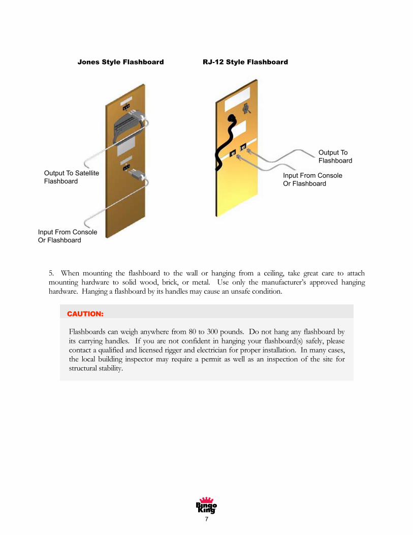
Jones Style Flashboard RJ-12 Style Flashboard
5. When mounting the flashboard to the wall or hanging from a ceiling, take great care to attachmounting hardware to solid wood, brick, or metal. Use only the manufacturer’s approved hanginghardware. Hanging a flashboard by its handles may cause an unsafe condition.
CAUTION:
Flashboards can weigh anywhere from 80 to 300 pounds. Do not hang any flashboard byits carrying handles. If you are not confident in hanging your flashboard(s) safely, pleasecontact a qualified and licensed rigger and electrician for proper installation. In many cases,the local building inspector may require a permit as well as an inspection of the site forstructural stability.
Jones Style Flashboard RJ-12 Style Flashboard
OutputToSatelliteFlashboard
InputFromConsoleOrFlashboard
OutputToFlashboard
InputFromConsoleOrFlashboard
E M E R A L D B I N G O C O N S O L E
7
Jones Style Flashboard RJ-12 Style Flashboard
5. When mounting the flashboard to the wall or hanging from a ceiling, take great care to attachmounting hardware to solid wood, brick, or metal. Use only the manufacturer’s approved hanginghardware. Hanging a flashboard by its handles may cause an unsafe condition.
CAUTION:
Flashboards can weigh anywhere from 80 to 300 pounds. Do not hang any flashboard byits carrying handles. If you are not confident in hanging your flashboard(s) safely, pleasecontact a qualified and licensed rigger and electrician for proper installation. In many cases,the local building inspector may require a permit as well as an inspection of the site forstructural stability.
8
E M E R A L D B I N G O C O N S O L E
8
Controls
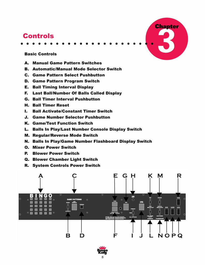
Basic Controls
A. Manual Game pattern switches
B. Automatic/Manual mode selector switch
C. Game Pattern Select Thumbwheel
D. Game Pattern Program Switch
E. Ball Timing Interval display
F. Last Ball/Number of balls called display
G. Ball Timer Interval thumbwheel
H. Ball Timer Reset
I. Ball Activate/Constant Timer switch
J. Game Number Selector thumbwheel
K. Game/Test Function switch
L. Balls In Play/Last Number console display switch
M. Regular/Reverse mode switch
N. Balls in Play/Game Number flashboard display switch
O. Mixer power switch
P. Blower power switch
Q. Blower chamber light switch
R. System controls power switch
Chapter
3Basic Controls
A. Manual Game Pattern Switches
B. Automatic/Manual Mode Selector Switch
C. Game Pattern Select Pushbutton
D. Game Pattern Program Switch
E. Ball Timing Interval Display
F. Last Ball/Number Of Balls Called Display
G. Ball Timer Interval Pushbutton
H. Ball Timer Reset
I. Ball Activate/Constant Timer Switch
J. Game Number Selector Pushbutton
K. Game/Test Function Switch
L. Balls In Play/Last Number Console Display Switch
M. Regular/Reverse Mode Switch
N. Balls In Play/Game Number Flashboard Display Switch
O. Mixer Power Switch
P. Blower Power Switch
Q. Blower Chamber Light Switch
R. System Controls Power Switch
Controls 3Chapter

9
Game Pattern Controls
1.ManualGamePatternSwitches—(A).These25pushbuttonswitchescontrolthegamepatternlightson the flashboard when switch (B) is set in the manual position. These switches are also used to set programmablegamepatterns.
2.Automatic/ManualModeSelectorSwitch—(B).IntheAutomaticmode,theoperatorcanrecallanddisplay previously user-programmed game patterns on the flashboard. In the Manual mode, the game patternlightsareundercontrolof theManualGamePatternswitches(A).Thisswitchmustbeinthemanualmodetoprogramgamepatterns.
3. Game Selection Pushbutton—(C). There are 100 possible user-programmable game patternsselectablebythe2-digitpushbutton(0-99).
4.GameProgramSwitch—(D).Bypressingthisbutton,youwillenterintomemorythegamepatternyou’vecreatedwiththeManualGamePatternswitches(A).(RefertoGamePatternProgrammingandRecalling,Pg.11).
Console Display Controls
1.BallTimingIndicatorDisplay—(E)ThisLEDdisplaysthetimeintervalbeforethenextballistobecalledandcountsdowntozerofromthetimesetontheBallTimerIntervalPushbutton.(G)Thebeeperwillindicatewhenitistimeforthenextcall.
2.Console—LastBall/Numberof BallsCalledDisplay—(F)ThisLEDdisplayiscontrolledbyswitch(L)anddisplayseithertheLastNumberCalledorTotalNumberof Ballsinplay.
3.BallTimerIntervalPushbutton—(G)Thispushbuttonsetsthetimeintervaltheoperatorchoosesbetweenballcalls.
4.BallTimerResetSwitch—(H)ThisbuttonrestartsthetimingsequenceattheTimerIntervalsetontheBallTimerIntervalPushbutton.(G)
5.Console—Balls inPlay/LastNumberCalledDisplay Switch—(L)This switch controls theLEDdisplayontheconsole(F).IntheBallsInPlayposition,thedisplayshowsthecallerthetotalnumberof ballscalledinthecurrentgame.IntheLastNumberCalledposition,thedisplayshowsthecallerwhichballwascalledlast.
6. Timer Selector—(I) Ball Activated/Constant—This switch controls the timer and allows theoperator to select one of the two functions. The first is the Constant function. In this mode, the timer willcountdownfromitspresettimerintervaltozero,signalwithabeeptoindicatetotheoperatorthatitistimetocallthenextballandstartitscountdownagain.IntheBallActivatedTimermode,thetimerwillalsocountdownfromitspresettimerintervaltozeroandgiveanaudiblesignal;butitwillnotresetuntilthenextballisinsertedintotheballtray.

�0
E M E R A L D B I N G O C O N S O L E
10
Flashboard Controls
1. Game/Test Function Switch—(K) In Game position, all lights in the flashboard are under control ofthe game features in the console. In test mode, all lights in the flashboard should illuminate to checkproper operation.
Note:
In the Test mode, the Numeric Display on the flashboard may show “80” instead of “88”,which is normal on some flashboards.
2. Regular/Reverse Mode Switch—(M) In the Regular position, the flashboard will light the number(s)called, while numbers not yet called remain dark. In the reverse position, all numbers will light, and as eachnumber is called, it will go out. This is an interesting variation to use for coveralls and/or call backs.
3. Ball in Play/Game Number Display Switch—N) In the Game Number position, the seven segmentnumber display on the flashboard will show the number of the current game and is under control of thethumbwheel (J). In the Balls in Play position, the flashboard numeric display will show how many ballshave been called in the current game.
4. Game Number Selector Thumbwheel—(J) These thumbwheels set the number of the game currentlyin play.
1. Game/Test Function Switch—(K) In Game position, all lights in the flashboard are under control of the game features in the console. In Test mode, all lights in the flashboard should illuminate to check properoperation.
2. Regular/Reverse Mode Switch—(M) In the Regular position, the flashboard will light the number(s) called,whilenumbersnotyetcalledremaindark.IntheReverseposition,allnumberswilllight,andaseachnumberiscalled,itwillgoout.Thisisaninterestingvariationtouseforcoverallsand/orcallbacks.
3.BallinPlay/GameNumberDisplaySwitch—(N)IntheGameNumberposition,thesevensegmentnumber display on the flashboard will show the number of the current game and is under control of the pushbutton (J). In the Balls in Play position, the flashboard numeric display will show how many balls havebeencalledinthecurrentgame.
4.GameNumberSelectorPushbutton—(J)Thesepushbuttonssetthenumberof thegamecurrentlyinplay.

��
E M E R A L D B I N G O C O N S O L E
11
Game Pattern
Programming and
Recall
Programming your Emerald Bingo Console
1. Set the Automatic/Manual switch (B) to Manual.
2. Use the Game Pattern Selection Thumbwheel switch (C) to establish in chronological order yourgame pattern numbers (0-99).
3. Use the 25 Manual Game Pattern Switches to design your game pattern. (A)
4. Push the square Program switch (D) to enter the pattern in memory.
5. Repeat steps 2-4. (Remember to advance the Game Pattern Selection thumbwheel.)
Note
Any game pattern may be altered at any given time by simply following the aboveprocedures.
Recalling Patterns on your Emerald Bingo Console
1. Slide or switch the Manual/Automatic switch (B) to automatic.
2. Rotate the Game Pattern Selection Thumbwheel switch (C) to select the appropriate pattern you wouldlike to recall.
Note:
If you wish NOT to program any patterns, leave the Manual/Automatic switch in theManual position and then enter the pattern you want to play on the Manual Game Patternswitches by pressing the individual switches down. To deselect a switch, just repress tobring it back to its top position.
Chapter
4Game Pattern Programming and Recall 4
Chapter
1.SettheAutomatic/Manualswitch(B)toManual.
2.UsetheGamePatternSelectionPushbuttonswitch(C)toestablishinchronologicalorderyourgamepatternnumbers(0-99).
3.Usethe25ManualGamePatternSwitchestodesignyourgamepattern.(A)
4.PushthesquareProgramswitch(D)toenterthepatterninmemory.
5.Repeatsteps2-4.(RemembertoadvancetheGamePatternSelectionpushbutton.)
1.SlideorswitchtheManual/Automaticswitch(B)toautomatic.
2.PushtheGamePatternSelectionPushbutton(C)toselecttheappropriatepatternyouwouldliketorecall.

��
E M E R A L D B I N G O C O N S O L E
12
Pattern Programming Worksheet
Pushbutton Settings
��
E M E R A L D B I N G O C O N S O L E
13
Operation
Playing A Game
To begin a bingo session, turn on the console power switch, the blower lampswitch, mixer motor switch, and blower motor switch on the Emerald Bingoconsole. You will notice that the balls will immediately go up the ball tube andare held in the ball catcher available for play.
Next, power on the any additional flashboards connected to your Emeraldconsole. By setting the Game/Test switch to Test, all lights on the flashboards will light up. This is veryhelpful to check light bulbs before playing bingo.
The Regular/Reverse switch is most often used in the regular mode; however, you may add variety toyour session by using the reverse mode for coveralls, or for expediting callbacks.
The ball timer will evenly pace your ball calling and build player confidence to play additional bingo faces,thus increasing revenues. Until you find a time that’s comfortable for you and your players, a good callingtime might be every 14 to 20 seconds. When the beeper sounds, it is time to call the next ball.
When a player yells “BINGO,” audience participation and excitement can be heightened by flashing thelights on the flashboards with the Test mode on the Game/Test switch.
At this time, verify all the bingos that have been called. It is usually best if the floor worker calls out theserial number of the bingo paper to verify purchase from your hall. Thenhave the floor worker call out each number in the bingo pattern from thebingo card with the caller confirming each call.
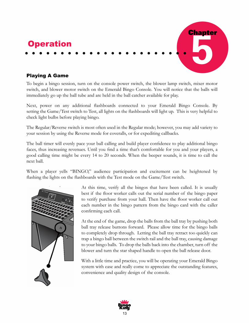
At the end of the game, drop the balls from the ball tray by pushing both balltray release buttons forward. Please allow time for the bingo balls tocompletely drop through. Letting the ball tray retract too quickly can trap abingo ball between the switch rail and the ball tray, causing damage to yourbingo balls. To drop the balls back into the chamber, turn off the blower andturn the star shaped handle to open the ball release door.
With a little time and practice, you will be operating your Emerald Bingosystem with ease and really come to appreciate the outstanding features,convenience and quality design of the console.
Chapter
5Playing A Game
Tobeginabingosession,turnontheconsolepowerswitch,theblowerlampswitch,mixermotorswitch,andblowermotorswitchontheEmeraldBingoConsole.Youwillnoticethattheballswillimmediatelygouptheballtubeandareheldintheballcatcheravailableforplay.
Next, power on any additional flashboards connected to your Emerald Bingo Console. By setting the Game/Test switch to Test, all lights on the flashboards will light up. This is very helpful to checklightbulbsbeforeplayingbingo.
TheRegular/ReverseswitchismostoftenusedintheRegularmode;however,youmayaddvarietytoyoursessionbyusingtheReversemodeforcoveralls,orforexpeditingcallbacks.
The ball timer will evenly pace your ball calling and build player confidence to play additional bingo faces, thus increasing revenues. Until you find a time that’s comfortable for you and your players, a goodcallingtimemightbeevery14to20seconds.Whenthebeepersounds, it is timetocall thenextball.
When a player yells “BINGO,” audience participation and excitement can be heightened byflashing the lights on the flashboards with the Test mode on the Game/Test switch.
At this time, verify all the bingos that have been called. It is usuallybest if the floor worker calls out the serial number of the bingo paper to verify purchase from your hall. Then have the floor worker call out eachnumber in thebingopatternfromthebingocardwiththecallerconfirming each call.
Attheendof thegame,droptheballsfromtheballtraybypushingbothballtrayreleasebuttonsforward.Pleaseallowtimeforthebingoballstocompletelydropthrough.Lettingtheballtrayretracttooquicklycantrapabingoballbetweentheswitchrailandtheballtray,causingdamagetoyourbingoballs.Todroptheballsbackintothechamber,turnoff theblowerandturnthestarshapedhandletoopentheballreleasedoor.
Withalittletimeandpractice,youwillbeoperatingyourEmeraldBingosystemwitheaseandreallycometoappreciatetheoutstandingfeatures,convenienceandqualitydesignof theconsole.
Operation 5Chapter
��
E M E R A L D B I N G O C O N S O L E
14
Customer Servicing
Cleaning
CAUTION:
Turn off and unplug your console and/or flashboard beforeperforming any maintenance. Failing to perform this veryimportant step could lead to equipment damage and/or personal injury!
Console Laminated & Painted surfaces: Use a soft cloth and mild soap solution to wipe away anydust and dirt that may accumulate. Harsh solvents or cleansers may damage paint, the laminate, orconsole lettering.
Console and Flashboard Acrylic surfaces: Use only a mild soap solution and a soft cloth. Do notuse an ammonia-based cleaning agent, as this will dull and etch the acrylic surface.
CAUTION:
Many flashboard manufacturers paint the flashboard acrylic on the outside. Using harshchemicals or abrasive cloths can remove the paint and damage the look and operation of theflashboard.
Bingo Balls: Clean with a mild soap solution. Harsh solvents or cleansers may damage and/or warpyour quality bingo balls. Make sure to allow the balls to dry thoroughly.
CAUTION:
Do NOT use hot water to wash your bingo balls. If the balls are in hot water for just ashort time, they can pop open. The air inside the ball will expand beyond the capacity of theball and the ball will split open, ruining the ball.
Note:
If your bingo balls do not seem to be moving freely after cleaning, make sure they arecompletely dry and place them in a large paper bag with a very LIGHT coating of talcumpowder and shake vigorously. This will allow them to move more freely and help preventstatic build-up.
Chapter
6CAUTION:
Turn off and unplug your console and/or flashboard before performinganymaintenance.Failingtoperformthisveryimportantstepcouldleadtoequipmentdamageand/orpersonalinjury!
Customer Servicing 6Chapter
��
E M E R A L D B I N G O C O N S O L E
15
Static Treatment
Lightly spray anti-static aerosol compound approved for plastics over the blower base pan foam andinside the blower chamber windows to eliminate static. Use sparingly and only when needed. Also checkto make sure your static tinsel is still intact. If worn or torn, call your distributor for service and/or parts.
CAUTION:
Do not spray the ball tube with anti-static spray. This may damage the ball tube even if it is“Plastic Safe” anti-static spray.
Changing Light Bulbs
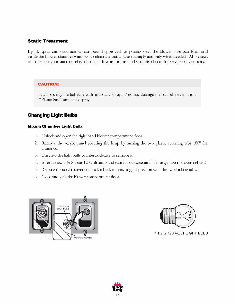
Mixing Chamber Light Bulb:
1. Unlock and open the right hand blower compartment door.
2. Remove the acrylic panel covering the lamp by turning the two plastic retaining tabs 180° forclearance.
3. Unscrew the light bulb counterclockwise to remove it.
4. Insert a new 7½ S clear 120 volt lamp and turn it clockwise until it is snug. Do not over-tighten!
5. Replace the acrylic cover and lock it back into its original position with the two locking tabs.
6. Close and lock the blower compartment door.
7�/�S��0VOLTLIGHTBULB
�6
E M E R A L D B I N G O C O N S O L E
16
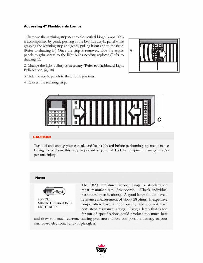
Accessing 4” Flashboards Lamps
1. Remove the retaining strip next to the vertical bingo lamps. Thisis accomplished by gently pushing in the low side acrylic panel whilegrasping the retaining strip and gently pulling it out and to the right.(Refer to drawing B.) Once the strip is removed, slide the acrylicpanels to gain access to the light bulbs needing replaced.(Refer todrawing C).
2. Change the light bulb(s) as necessary (Refer to Flashboard LightBulb section, pg. 18)
3. Slide the acrylic panels to their home position.
4. Reinsert the retaining strip.
Note:
The 1820 miniature bayonet lamp isstandard on most manufacturers’flashboards. (Check individualflashboard specifications) A good lampshould have a resistance measurement ofabout 28 ohms. Inexpensive lamps
often have a poor quality and do not have consistent resistance ratings.Using a lamp that is too far out of specifications could produce too muchheat and draw too much current, causing premature failure and possibledamage to your flashboard electronics and/or plexiglass.
Bingo King FlashboardPage 7
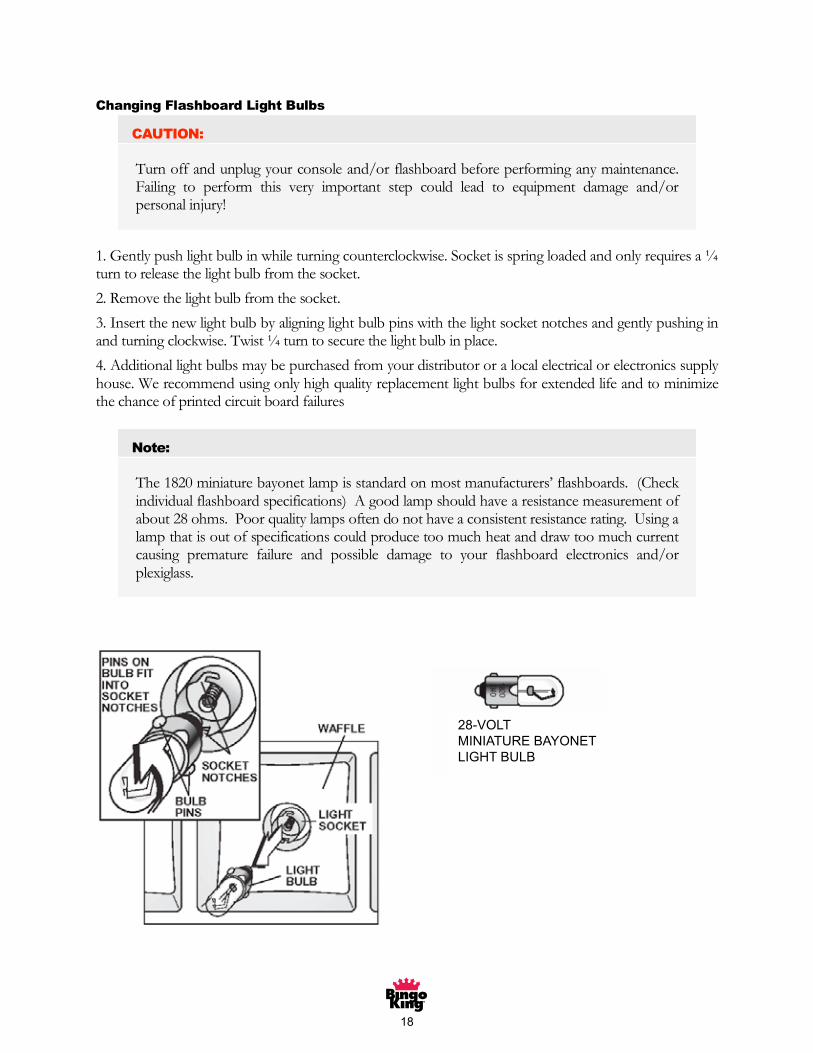
Changing Flashboard Light Bulbs
CAUTION:
Turn off and unplug your console and/or flashboard before performing any maintenance.Failing to perform this very important step could lead to equipment damage and/orpersonal injury!
1. Gently push light bulb in while turning counterclockwise. Socket is spring loaded and only requires a¼turn to release the light bulb from the socket.
2. Remove the light bulb from the socket.
3. Insert the new light bulb by aligning light bulb pins with the light socket notches and gently pushing inand turning clockwise. Twist¼ turn to secure the light bulb in place.
4. Additional light bulbs may be purchased from your distributor or a local electrical or electronics supplyhouse. We recommend using only high quality replacement light bulbs for extended life and to minimizethe chance of printed circuit board failures
Note:
The 1820 miniature bayonet lamp is standard on most manufacturers’ flashboards. (Checkindividual flashboard specifications) A good lamp should have a resistance measurement ofabout 28 ohms. Poor quality lamps often do not have a consistent resistance rating. Using alamp that is out of specifications could produce too much heat and draw too much currentcausing premature failure and possible damage to your flashboard electronics and/or
plexiglass.
E M E R A L D B I N G O C O N S O L E
16
Accessing 4” Flashboards Lamps
1. Remove the retaining strip next to the vertical bingo lamps. Thisis accomplished by gently pushing in the low side acrylic panel whilegrasping the retaining strip and gently pulling it out and to the right.(Refer to drawing B.) Once the strip is removed, slide the acrylicpanels to gain access to the light bulbs needing replaced.(Refer todrawing C).
2. Change the light bulb(s) as necessary (Refer to Flashboard LightBulb section, pg. 18)
3. Slide the acrylic panels to their home position.
4. Reinsert the retaining strip.
Note:
The 1820 miniature bayonet lamp isstandard on most manufacturers’flashboards. (Check individualflashboard specifications) A good lampshould have a resistance measurement ofabout 28 ohms. Inexpensive lamps
often have a poor quality and do not have consistent resistance ratings.Using a lamp that is too far out of specifications could produce too muchheat and draw too much current, causing premature failure and possibledamage to your flashboard electronics and/or plexiglass.
Note:
The 1820 miniature bayonet lamp is standard onmost manufacturers’ flashboards. (Check individual flashboard specifications). A good lamp should have a resistancemeasurementof about28ohms.Inexpensive
lamps often have a poor quality and do not haveconsistent resistanceratings. Usinga lampthat is toofar out of specifications could produce too much heat
anddraw toomuchcurrent, causingpremature failureandpossibledamage toyourflashboard electronics and/or plexiglass.
�7
E M E R A L D B I N G O C O N S O L E
17
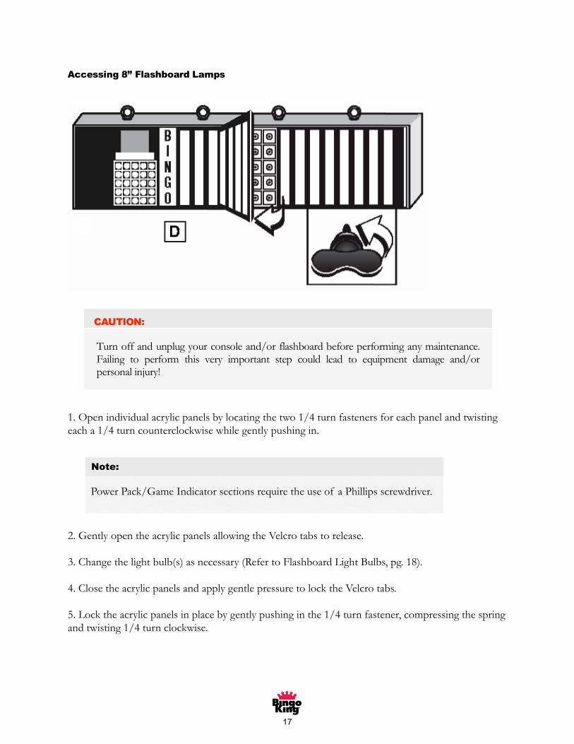
Accessing 8” Flashboard Lamps
1. Open individual acrylic panels by locating the two 1/4 turn fasteners for each panel and twisting each a1/4 turn counterclockwise while gently pushing in.
Note:
Power pack/Game Indicator sections require the use of a Phillips screwdriver
2. Gently open the acrylic panels allowing the Velcro tabs to release.
3. Change the light bulb(s) as necessary. (Refer to Flashboard Light Bulbs pg. 18)
4. Close the acrylic panels and apply gentle pressure to lock the Velcro tabs.
5. Lock the acrylic panels in place by gently pushing in the 1/4 turn fastener, compressing the spring and
twisting¼ turn clockwise.
1.Openindividualacrylicpanelsbylocatingthetwo1/4turnfastenersforeachpanelandtwistingeacha1/4turncounterclockwisewhilegentlypushingin.
2.GentlyopentheacrylicpanelsallowingtheVelcrotabstorelease.
3.Changethelightbulb(s)asnecessary(RefertoFlashboardLightBulbs,pg.18).
4.ClosetheacrylicpanelsandapplygentlepressuretolocktheVelcrotabs.
5.Locktheacrylicpanelsinplacebygentlypushinginthe1/4turnfastener,compressingthespringandtwisting1/4turnclockwise.
Note:
PowerPack/GameIndicatorsectionsrequiretheuseof aPhillipsscrewdriver.
Bingo King FlashboardPage 7
Changing Flashboard Light Bulbs
CAUTION:
Turn off and unplug your console and/or flashboard before performing any maintenance.Failing to perform this very important step could lead to equipment damage and/orpersonal injury!
1. Gently push light bulb in while turning counterclockwise. Socket is spring loaded and only requires a¼turn to release the light bulb from the socket.
2. Remove the light bulb from the socket.
3. Insert the new light bulb by aligning light bulb pins with the light socket notches and gently pushing inand turning clockwise. Twist¼ turn to secure the light bulb in place.
4. Additional light bulbs may be purchased from your distributor or a local electrical or electronics supplyhouse. We recommend using only high quality replacement light bulbs for extended life and to minimizethe chance of printed circuit board failures
Note:
The 1820 miniature bayonet lamp is standard on most manufacturers’ flashboards. (Checkindividual flashboard specifications) A good lamp should have a resistance measurement ofabout 28 ohms. Poor quality lamps often do not have a consistent resistance rating. Using alamp that is out of specifications could produce too much heat and draw too much currentcausing premature failure and possible damage to your flashboard electronics and/or
plexiglass.
�8
E M E R A L D B I N G O C O N S O L E
18
Changing Flashboard Light Bulbs
CAUTION:
Turn off and unplug your console and/or flashboard before performing any maintenance.Failing to perform this very important step could lead to equipment damage and/orpersonal injury!
1. Gently push light bulb in while turning counterclockwise. Socket is spring loaded and only requires a¼turn to release the light bulb from the socket.
2. Remove the light bulb from the socket.
3. Insert the new light bulb by aligning light bulb pins with the light socket notches and gently pushing inand turning clockwise. Twist¼ turn to secure the light bulb in place.
4. Additional light bulbs may be purchased from your distributor or a local electrical or electronics supplyhouse. We recommend using only high quality replacement light bulbs for extended life and to minimizethe chance of printed circuit board failures
Note:
The 1820 miniature bayonet lamp is standard on most manufacturers’ flashboards. (Checkindividual flashboard specifications) A good lamp should have a resistance measurement ofabout 28 ohms. Poor quality lamps often do not have a consistent resistance rating. Using alamp that is out of specifications could produce too much heat and draw too much currentcausing premature failure and possible damage to your flashboard electronics and/orplexiglass.
�8-VOLTMINIATUREBAYONETLIGHTBULB

�9
E M E R A L D B I N G O C O N S O L E
19
Blower & Mixer Maintenance
The blower and mixer motor should be serviced every four months or every 200 operating hours.
CAUTION:
Turn off and unplug your console and/or flashboard before performing any maintenance.Failing to perform this very important step could lead to equipment damage and/orpersonal injury!
1. Unplug the console power cord from the wall outlet.
2. Unlock and open the right-hand-side blower compartmentdoor. Remove any balls that may be on the blower base panassembly.
3. Disconnect the power plug located below the blower basepan, remove the one screw on the base pan, and pull theassembly out of the console.
4. Lay the removed blower base pan assembly upside downon a flat surface, remove the four Phillips screws (two fromeach side) from the protective guard, and lay the protectiveguard on its side.
5. Put a few drops of 20W oil into the two oiling portslocated on the top side at each end of the blower motor.(Refer to illustration.)
6. Oil the mixer motor by removing the two 1/4” bolts fromthe rear plate of the mixer motor. Oil the felt pad with 20Woil, replace plate and reinsert the bolts, being careful not toover tighten them.
7. Check the blower motor squirrel cage blades fordebris. If dirty, loosen the cage from the shaft with a1/8”Allen wrench and remove from the shaft. Clean theblades with a small stiff brush, using soap and water, andtowel dry. Reinstall the squirrel cage and check that theblades are free wheeling and not binding.
9. Reassemble and carefully slide the base pan back intothe console with the mixer arm pointing towards thefront of the console.
10. Inspect the air filter and replace if necessary.
11. Make sure to reconnect the four-pin power plug. Reinsert bingo balls onto blower base pan assembly,close and lock blower compartment door.
10. Inspect the air filter and replace if necessary. (Refer toConsoleAirFilterReplacement,pg.20)
11.Makesuretoreconnectthefour-pinpowerplug.Reinsertbingoballsontoblowerbasepanassembly,closeandlockblowercompartmentdoor.

�0
E M E R A L D B I N G O C O N S O L E
20
Console Air Filter Replacement
Note:
The console air filter should be checked regularly. A clogged air filter can cause the balls tohave poor ball chamber action and possibly not allow them to push up the ball tube.
1. Turn off power and unplug the console.
2. Unlock and open the ball chamber door.
3. Locate the air filter in the bottom of the blower chamber located under the blower base pan.
4. Rotate the plastic locking tabs out of the way and remove the air filter.
5. Replace with a clean air filter obtained through your Emerald console distributor.
1. Turnoff powerandunplugtheconsole.
2. Unlockandopentheballchamberdoor.
3. Locate the air filter in the bottom of the blower chamber located under the blower base pan.
4. Rotate the plastic locking tabs out of the way and remove the air filter.
5. Replace with a clean air filter obtained through your Emerald Bingo Console distributor.

��
E M E R A L D B I N G O C O N S O L E
21
Fuse Replacement
There are two fuses on your Emerald Bingo console: A 6 amp AGC (fast blow) and a 0.3 amp MDL(slow blow). The 6 amp fuse is for the blower, mixer, and lights; while the 0.3 amp fuse handles thecircuit board power..
CAUTION:
Do not attempt to replace the fuses without turning off all power and unplugging theconsole. Failure to do so could expose you to dangerous current.
CAUTION:
Using fuses that are incorrectly rated for your machine can cause equipment damage and/orpersonal injury. If your fuse is consistently failing, the problem causing the fuse to fail mustbe corrected.
To replace the either of the fuses, gently push in on the fuse holder cap and turn counter clockwise ¼turn. This should release the cap and the fuse will come out with the cap. Replace only with fuses of thesame rating and type.
Note:
Sometimes fuses don’t always “look” bad. The fuse may have blown, and might not showthe normal “black and smoky” spot that is normally associated with a bad fuse. A bad fuseis one that when tested with an ohmmeter is open.
TherearetwofusesonyourEmeraldBingoConsole:A6ampAGC(fastblow)anda0.3ampMDL(slowblow).The6ampfuseisfortheblower,mixerandlights;whilethe0.3ampfusehandlesthecircuitboardpower.
Toreplaceeitherof thefuses,gentlypushinonthefuseholdercapandturncounterclockwise1/4turn.Thisshouldreleasethecapandthefusewillcomeoutwiththecap.Replaceonlywithfusesof thesameratingandtype.
��
E M E R A L D B I N G O C O N S O L E
22
Troubleshooting
Before attempting any of the following troubleshooting steps, make sure yourconsole and/or flashboard are plugged into a stable power outlet. The outletshould provide at least 108 VAC. If the voltage is too low, your bingoequipment will not function correctly. The troubleshooting guide assumes thepower connections have already been checked and are working.
Note:
When troubleshooting your bingo system, please take note where and when the problemsare occurring. If a problem is only present in one flashboard out of many, then the problemis not likely to be in the console, but rather in the flashboard. On the other hand, if theproblems are on all flashboards in your hall then it is very likely the problems are associatedwith the console.
Blower Motor Troubleshooting
Blower stopped working:
• Check to make sure the console is plugged in and the outlet voltage is sufficient.
• Make sure the blower power switch is on. (See page 8 for details)
• Make sure the 6 amp fuse is good. (See page 21 for details)
• Make sure the connection at the blower base pan is fully connected. (Especially if the blowerbase pan has been removed recently.)
• Possible defective blower switch.
• Possible defective blower.
Blower operates slowly
• Air filter maybe clogged. Replace with new one. (See page 20)
• Blower may need to be oiled. (See page 19)
• Have the console’s casters been removed or is the console sitting on thick carpet? If so, theremight not be enough air flow under the console to allow for the free movement of air. Raisethe console to allow a greater volume of air to move under the frame.
• Line voltage may be low. If your line voltage is below 108 VAC the blower and mixer motorswill run slower and not very efficiently. Check with an electrician to troubleshoot thebuilding’s electrical service.
Chapter
7Troubleshooting 7
Chapter
• Air filter may be clogged. Replace with new one. (See page 20)

��
E M E R A L D B I N G O C O N S O L E
23
Mixer Motor Troubleshooting
Mixer motor stopped working
• Check to make sure the console is plugged in and the outlet voltage is sufficient.
• Make sure the mixer motor switch is on. (See page 8 for details)
• Make sure the 6 amp fuse is good. (See page 21 for details)
• Make sure the connection at the blower base pan is fully connected. (Especially if the blowerbase pan has been removed recently.)
• Possible defective mixer motor switch.
• Possible bad mixer motor.
Mixer motor running slow
• Check to make sure the console is plugged in and the outlet voltage is sufficient.
• Oil the mixer motor. (See page 19)
• Possible bad mixer motor.
Flashboard Output Problems
Flashboard lights flicker
• Possible loose flashboard data connector. Check all flashboard connections on the consoleand flashboard.
• Defective test switch. If the test switch is beginning to fail, it may cause the lights on theflashboard to flicker in and out of test mode.
• Defective reverse switch. If the reverse switch is beginning to fail, the lights on the flashboardmay flicker in and out of reverse mode.
• Defective flashboard PCB. (Contact distributor for replacement or repair.)
• Defective console PCB. (Contact distributor for replacement or repair.)
No flashboard response
• Possible defective data cable. Check the data cable from the console to the first flashboard tomake sure it is in good condition, and replace any damaged cabling. Run a known good cableeven if no damage is visible. Of course, if the replacement cable works, then the previouscable must have been bad.
• The first flashboard in the chain is bad. The signal coming out of the console might be good,but if the first flashboard in the chain is bad it will not display information, and also will notpass the signal on to the other flashboards in the chain. Unplug all data cables from theconsole and run a known good cable to one of the other flashboards in the chain to check forfunctionality. If this works, there may be a bad flashboard or cable in the chain. (See abovestep for bad cable.) Check your flashboard distributor or manufacturer about troubleshootingand diagnosing a defective flashboard.
• 0.3 amp fuse has blown. (See page 21 for fuse troubleshooting)
• Defective console printed circuit board. Contact your distributor for repair or replacementoptions.
• Possible loose flashboard data connector. Check all flashboard connections on the console and flashboard.
• DefectiveTestswitch.If theTestswitchisbeginningtofail,itmaycausethelightsonthe flashboard to flicker in and out of Test mode.
• DefectiveReverse switch. If theReverse switch isbeginning to fail, the lightson the flashboard may flicker in and out of Reverse mode.
• Defective flashboard PCB. (Contact distributor for replacement or repair.)
• DefectiveconsolePCB.(Contactdistributorforreplacementorrepair.)
��
Wiring Diagrams and PCB Layouts 8
Chapter
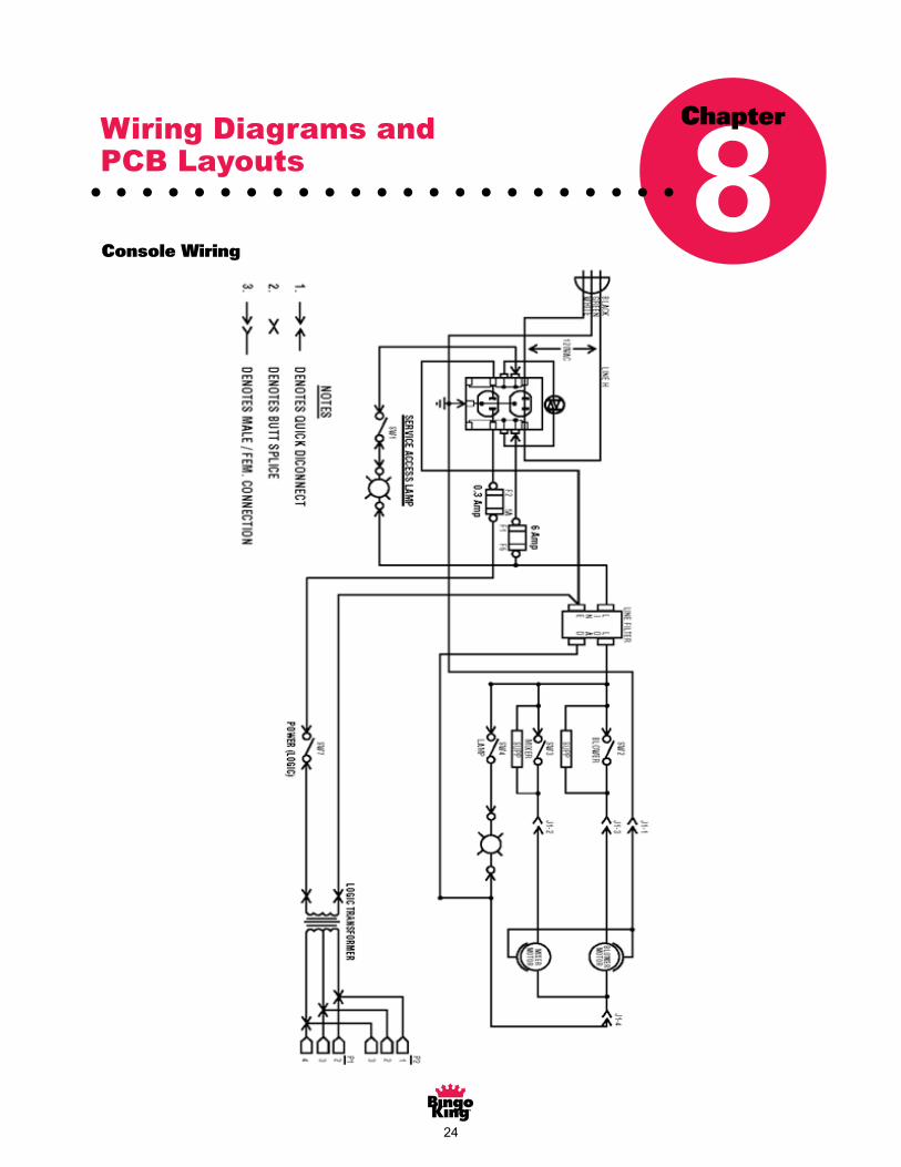
Console Wiring

��
Console Switch Wiring
�6
E M E R A L D B I N G O C O N S O L E
26
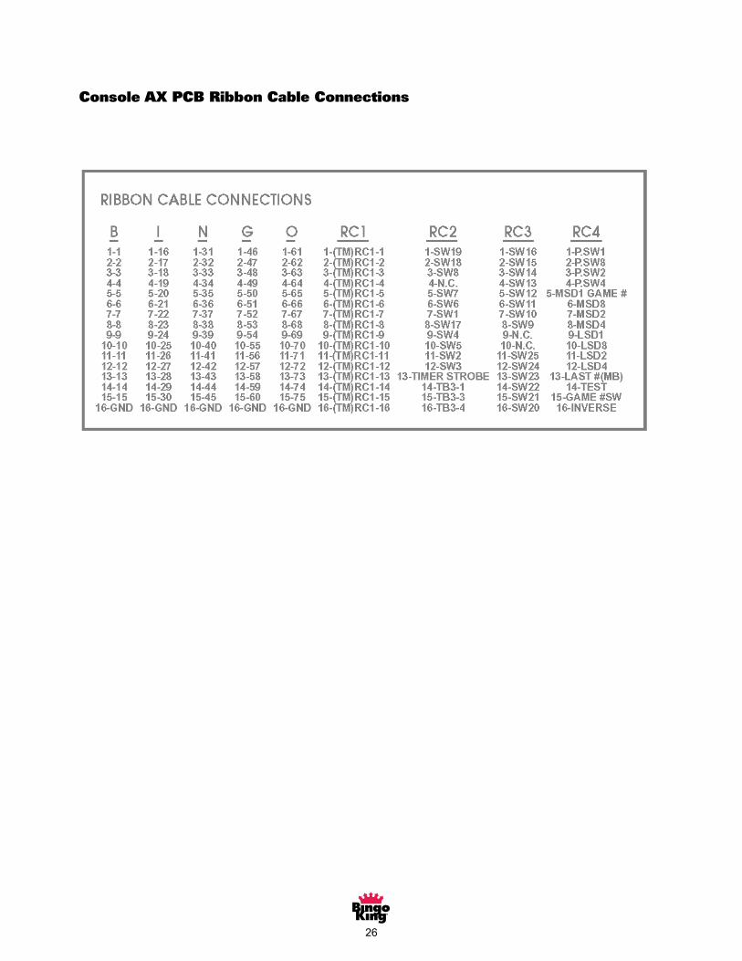
Console AX PCB Ribbon Cable connectionsConsole AX PCB Ribbon Cable Connections
�7
E M E R A L D B I N G O C O N S O L E
27
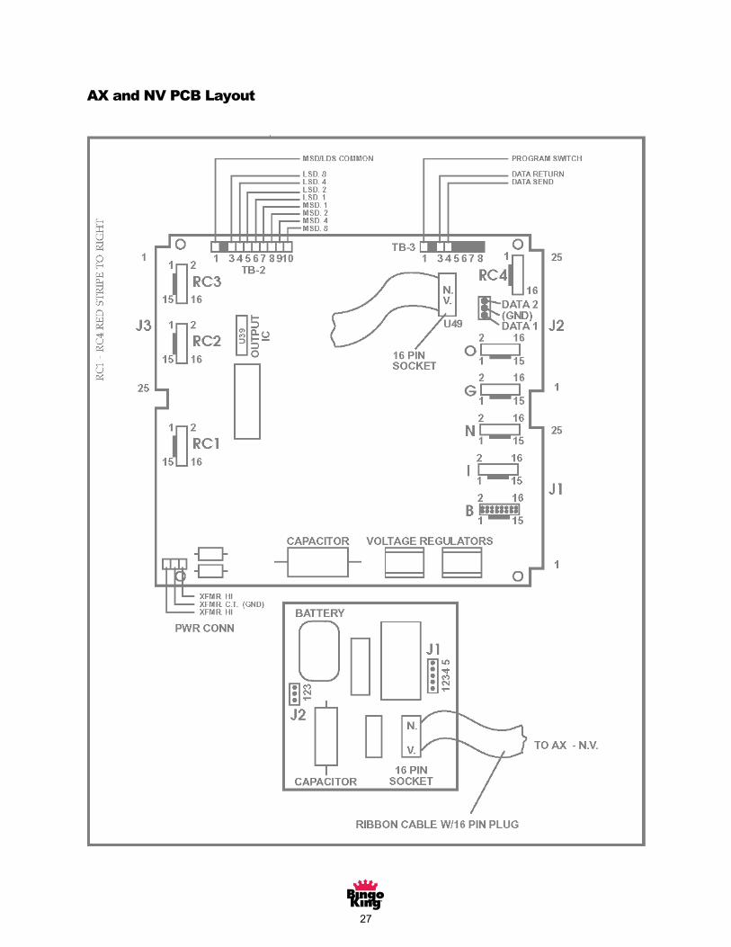
AX and NV PCB Layout

�8
AT (Timer) PCB Layout
�9
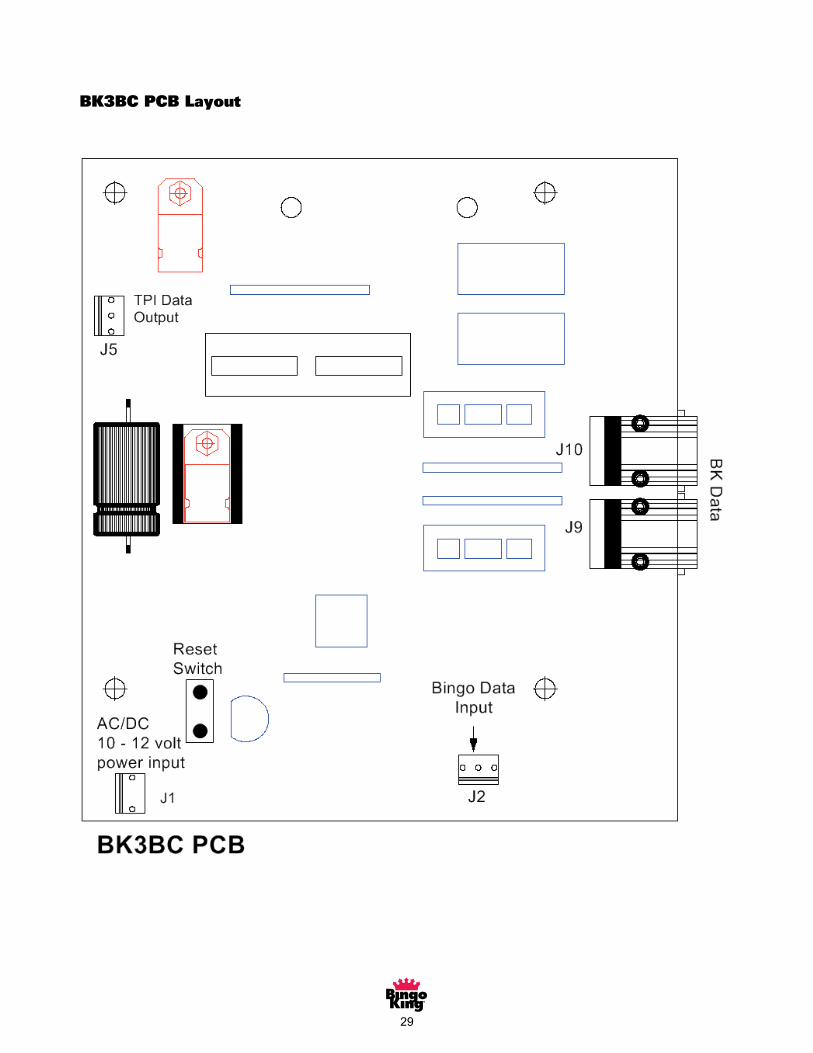
BK3BC PCB Layout
�0
Warranty 9Chapter
Bingo King® Bingo Console Standard Limited Warranty
SetoutbelowarethetermsoftheStandardLimitedWarranty(“LimitedWarranty”)made by Bingo King Co. (“Bingo King”) in connection with the sale of the Bingo King equipment(the“Equipment”).1. Limited WarrantySubjecttothelimitationsinthenextparagraph,BingoKingwarrantstotheoriginalpurchaser(“Purchaser”)that theEquipmentwill, to theextentmanufacturedbyBingoKing,be free fromdefects inmaterialandworkmanshipforaperiodofONE(�)YEARfromthedateofshipmentoftheEquipmentfromBingoKing.PurchaserrepresentstoBingoKingthatnoemployee,agent,orrepresentativeofBingoKing(oraBingoKingdealer)hasmadeanyrepresentationorwarrantyregardingtheEquipmentexceptassetoutherein.
ThisLimitedWarrantyappliestonormalcommercialuseanddoesnotcoverfailureordamagewhich(a)occurs in shipment; (b) is causedbyproducts not supplied byBingoKing; or (c) results fromaccident,misuse, abuse, neglect, mishandling, misapplication, alteration, set-up adjustments or modifications. This LimitedWarrantyalsodoesnotcoveranydamageresultingfromfailureto install theEquipment instrictconformity with local fire and building codes and regulations, or if the installation does not comply with the installationinstructionsprovidedbyBingoKing.Productswhicharemanufacturedbyathird-partyvendorandofferedwiththeEquipment(suchasmonitors,keyboards,cameras,andotherperipheralproducts)arenotcoveredbythisLimitedWarranty.Purchaserneedstoconsultthethird-partymanufacturer’swarrantyforwarrantyclaimsrelatedthereto.BingoKingwillsupplyacopyofanythird-partyvendor’swarrantyuponwrittenrequest.
2. Disclaimer of WarrantiesBINGO KING MAKES NO WARRANTIES, EXPRESS OR IMPLIED (INCLUDING, WITHOUT LIMITATION,MERCHANTABILITY, FITNESS FOR PARTICULAR PURPOSE, OR AGAINST INFRINGEMENT OF ANYPATENT),EXCEPTASEXPRESSLYPROVIDEDHEREIN.THEEXPRESSWARRANTIESPROVIDEDHEREINARE IN LIEU OFAND EXCLUDEALL OTHER WARRANTIES, GUARANTEES OR REPRESENTATIONS,EXPRESSORIMPLIED,WHETHERARISINGBYOPERATIONOFLAWOROTHERWISE.
3. Limitation of RemediesIftheEquipmentdoesnotconformtotheLimitedWarrantysetoutabove,BingoKingwill,atitsoption,(a)repairorreplacetheEquipment,orpartthereof,whichisdefective,or(b)refundsomuchofthepurchasepriceasPurchaserhaspaidforthedefectiveEquipment,less�/��thofthepurchasepriceforeachmonthbetweenthedateofthepurchasefromanauthorizedBingoKingdealerandthedateofthediscoveryofthedefect,providedthatwrittennoticeofthedefectanditsnatureisgiventoBingoKingassoonaspracticalafterdiscoveryofthedefect,butinnoeventlaterthan90daysfromthedateofthediscoveryofthedefect.AllpartrepairsarethroughtheBingoKingClevelandDepot.
4. Limitation of LiabilityThe remedy of repair, replacement, or refund of the purchase price is Purchaser’s sole and exclusiveremedyandwillsatisfyallofBingoKing’sliabilities,whetherbasedoncontract,negligence,tort,productliability, strict liability or otherwise. INNOEVENTWILLBINGOKINGBELIABLEFOR INCIDENTALORCONSEQUENTIAL DAMAGES, NOR WILL ITS LIABILITY IN CONNECTION WITHANY EQUIPMENT ORSERVICESOLD(INCLUDINGNONDELIVERYORLATEDELIVERYTHEREOF)EXCEEDTHESALEPRICEOFSUCHEQUIPMENT.
��
5. Warranty VoidedAny obligations of Bingo King under this Limited Warranty will be deemed to have been satisfied if anyone other than an authorizedBingoKingEquipmentDealerservicestheEquipment.6. Transfer of Limited WarrantyPurchasermaytransferitsrightsunderthisLimitedWarranty,subjecttothetermsandconditionshereof,toabuyer(“Buyer”)fromPurchaseroftheEquipment.Thereafter,therightsunderthisLimitedWarrantyarenottransferable.ForthetransferbyPurchaseroftheLimitedWarrantytobeeffective,thefollowingconditionsmusthaveoccurrednolaterthanthe�0thdayfollowingthedateofresaletoBuyer:
A. Purchaser must have complied with all requirements to make the Limited Warranty effective as to Purchaser;andB. TheEquipment(asanentireunitandaspurchasedbyPurchaser)mustbetransferredtoBuyer.
UponaneffectivetransferofthisLimitedWarranty,Buyerwillbeconsideredtobe“Purchaser”forparagraphs�,�and8hereof.
7. InspectionWith respect toanyclaim that theEquipment isdefective,BingoKingwillbealloweda reasonable time to inspect theEquipment,inplace.IftheEquipmentisalteredorremovedbeforeBingoKinghasmadesuchinspectionorwaiveditsrightto do so, the obligations of Bingo King under this Limited Warranty will be deemed to have been satisfied.
8. Proof of PurchaseNotwithstandinganythingtothecontraryinthisLimitedWarranty,Purchasermust,uponBingoKing’srequest,submitproofoforiginalpurchase(satisfactorytoBingoKing)oftheEquipment.TheLimitedWarrantysetoutaboveshallnotapplyto,norcover,anyEquipmentforwhichPurchaserisunable,uponBingoKing’srequest,tosupplysuchproofofpurchase.
9. Telephone SupportTelephonesupportisavailabletoPurchaseronMondaysthroughFridays(includingholidays)from8:00a.m.until��:00a.m.(EasternStandardTime).Thetelephonenumberis(866)�0�-��8�.
10. Preventative Maintenance; Emergency ServicePurchaserisentitledtorequestBingoKingtoperform,throughanauthorizedBingoKingdistributor,one(�)preventativemaintenance servicing on the Equipment. The preventative maintenance servicing shall be done in accordance withBingoKing’sstandardPreventativeMaintenanceprogram.ServiceperformedbyBingoKingoranBingoKingauthorizeddistributor,whichisnotcoveredunderitsstandardPreventativeMaintenanceprogram,willbebilledtoPurchaser.
11. Limitation of ActionsAnylegalactionagainstBingoKingforadefaultofitsobligationsunderthisLimitedWarrantymustbecommencedwithintwo(�)yearsfromthedatetheEquipmentwassoldbyanauthorizeddealeroftheEquipment.
12. How to Obtain ServiceIfaproblemwiththisEquipmentdevelopsduringorafterthewarrantyperiod,proceedasfollows:
A. RefertoyourOperator’sManualandfollowtheTroubleshootingTablewithinthe‘ServiceSection’.B. ContacttheauthorizedBingoKingEquipmentDistributorfromwhomyoupurchasedtheEquipment.C. ContacttheBingoKingtelephonesupportnumberlistedabove.
SERVICECALLSWHICHDONOTINVOLVEDEFECTIVEMATERIALSORWORKMANSHIPASDETERMINEDBYBINGOKINGINITSSOLEDISCRETIONARENOTCOVERED.THECOSTOFSUCHSERVICECALLSISTHERESPONSIBILITYOFTHEPURCHASER.
Bingo King wants you to remain a satisfied customer. If a problem occurs that cannot be resolved to your satisfaction, please contactusimmediately,phoneoneofthenumberslistedaboveorwriteto:
BingoKingCo.c/oNationalServiceManager
�807LincolnWayLynnwood,WA98087
Pleasebesuretoincludethename,modelnumber,serialnumber,dateoforiginalpurchase,andthedistributorfromwhomyoupurchasedtheEquipment,aswellasanyactionstakentocorrecttheproblem.

Bingo King Co. • 2807 Lincoln Way • Lynnwood, WA 98087 • 425.745.3700
PART#BKCMV�-MNL