
BK-DH 700 x 1000 eng - Amazon Web Services · BK-DH 700 x 1000 eng.doc BRUKS-KLÖCKNER 27.02.09 00...
62
Operating manual 17.410+411 Pos.: 20 Dateiname Firma Datum Rev BK-DH 700 x 1000 eng.doc BRUKS-KLÖCKNER 27.02.09 00 Seite 1 von 61 DRUM CHIPPER Type BK-DH 500 x .... BK-DH 700 x .... BK-DH 850 x ....
Transcript of BK-DH 700 x 1000 eng - Amazon Web Services · BK-DH 700 x 1000 eng.doc BRUKS-KLÖCKNER 27.02.09 00...

Operating manual 17.410+411 Pos.: 20
Dateiname Firma Datum Rev BK-DH 700 x 1000 eng.doc BRUKS-KLÖCKNER 27.02.09 00 Seite 1 von 61
DRUM CHIPPER
Type
BK-DH 500 x .... BK-DH 700 x .... BK-DH 850 x ....
Operating manual 17.410+411 Pos.: 20
Dateiname Firma Datum Rev BK-DH 700 x 1000 eng.doc BRUKS-KLÖCKNER 27.02.09 00 Seite 2 von 61
Contents
1 GENERAL COMMENTS ...................................................................................... 6
1.1 Preface................................................................................................................. 6
1.2 Intended purpose................................................................................................ 7
1.3 Copyright............................................................................................................. 7
2 SAFETY INSTRUCTIONS.................................................................................... 8
3 MACHINE DESCRIPTION ................................................................................... 11
3.1 Constructional design........................................................................................ 11
3.1.1 Rotor bearings .................................................................................................... 11
3.1.2 Feedroll carrier pivot .......................................................................................... 11
3.1.3 Lower feedrolls and bearings............................................................................ 11
3.1.4 Upper feedrolls and bearings ............................................................................ 11
3.1.5 Counter knife carrier .......................................................................................... 12
3.1.6 Rotor .................................................................................................................... 12
3.1.7 Hood .................................................................................................................... 12
3.1.8 Screen.................................................................................................................. 12
3.1.9 Feedroll carrier.................................................................................................... 12
3.1.10 Machine housing ................................................................................................ 12
3.1.11 Hydraulic plant.................................................................................................... 13
3.1.12 Motor plant .......................................................................................................... 13
3.1.13 Cradle support .................................................................................................... 13
3.1.14 Run-up device (if requested) ............................................................................. 14
3.1.15 Rotor hood locking device (if requested) ......................................................... 14
3.1.16 Rotor turning device (if requested) ................................................................... 15
3.1.17 Screen basket ..................................................................................................... 16
3.2 Functional description ....................................................................................... 17
3.2.1 Stock feed ........................................................................................................... 17

Operating manual 17.410+411 Pos.: 20
Dateiname Firma Datum Rev BK-DH 700 x 1000 eng.doc BRUKS-KLÖCKNER 27.02.09 00 Seite 3 von 61
3.2.2 Chipping operation............................................................................................. 17
3.2.3 Material distribution ........................................................................................... 17
3.2.4 Overload protection............................................................................................ 17
3.2.5 Start and run up.................................................................................................. 18
3.2.6 Hydraulic functions ............................................................................................ 18
4 TRANSPORTATION AND STORAGE................................................................. 20
4.1 Transport rules and regulations........................................................................ 20
4.2 Transportation fixtures ...................................................................................... 21
4.3 Storage at site..................................................................................................... 21
4.4 Break down for chipment................................................................................... 21
4.5 Scope of supply .................................................................................................. 22
5 INSTALLATION ................................................................................................... 23
5.1 General comments ............................................................................................. 23
5.2 Set-up and preliminary alignment ..................................................................... 24
5.3 Installation of hydraulic plant ............................................................................ 24
5.4 Installation of lower feedroll drive..................................................................... 25
5.5 Final alignment ................................................................................................... 25
5.6 Counterknife carrier guide rail installation....................................................... 26
5.7 Installation of hydraulic cylinder for anvil ........................................................ 26
5.8 Installation of motor and base........................................................................... 27
5.9 Installation of drive belt(s) and guard............................................................... 27
5.9.1 Applying and tensioning of V-belts................................................................... 28
5.10 Electrical installation.......................................................................................... 29
6 START-UP ........................................................................................................... 30
6.1 Preliminary checks ............................................................................................. 30
6.2 Starting ................................................................................................................ 31
6.3 Subsequent checks ............................................................................................ 31
7 OPERATING INSTRUCTIONS............................................................................. 32

Operating manual 17.410+411 Pos.: 20
Dateiname Firma Datum Rev BK-DH 700 x 1000 eng.doc BRUKS-KLÖCKNER 27.02.09 00 Seite 4 von 61
7.1 General comments ............................................................................................. 32
7.2 Operation of the machine .................................................................................. 32
7.3 Knife change (general) ....................................................................................... 33
7.3.1 Knife change ....................................................................................................... 33
7.3.1.1 Knife change ....................................................................................................... 35
7.3.1.2 Counter knife change with clamped anvils ...................................................... 36
8 INSPECTION AND MAINTENANCE.................................................................... 38
8.1 General comments ............................................................................................. 38
8.2 Maintenance and inspection list........................................................................ 39
8.3 Knives.................................................................................................................. 41
8.3.1 Knife grinding ..................................................................................................... 41
8.3.1.1 Grinding of knives .............................................................................................. 41
8.3.1.2 Grinding of counter knives ................................................................................ 42
8.3.2 Knife setting........................................................................................................ 43
8.3.3 Re- adjusting the jig ........................................................................................... 44
8.4 Hydraulic plant.................................................................................................... 44
8.4.1 Accumulator (only for hydraulic plant of the chipper) .................................... 44
8.4.1.1 Oil pressure p3.................................................................................................... 44
8.4.1.2 Gas pressure p1.................................................................................................. 45
8.4.2 System pressure................................................................................................. 46
8.4.3 Oil tank ................................................................................................................ 46
8.4.4 Filter..................................................................................................................... 46
8.4.5 Hydraulic hoses.................................................................................................. 47
8.4.6 Pipework.............................................................................................................. 47
8.5 Gear motors ........................................................................................................ 47
8.6 Electrical motors................................................................................................. 47
8.7 Couplings ............................................................................................................ 47
8.8 Belt drive ............................................................................................................. 47

Operating manual 17.410+411 Pos.: 20
Dateiname Firma Datum Rev BK-DH 700 x 1000 eng.doc BRUKS-KLÖCKNER 27.02.09 00 Seite 5 von 61
8.8.1 V-belt.................................................................................................................... 47
8.8.2 Flat belts.............................................................................................................. 48
8.9 Chain drive .......................................................................................................... 48
8.10 Rotor wear plates (optional) .............................................................................. 49
8.11 Feedrolls.............................................................................................................. 49
8.12 Screen.................................................................................................................. 50
8.13 Lubrication .......................................................................................................... 50
9 TROUBLE SHOOTING ........................................................................................ 51
9.1 Problems with the chip quality .......................................................................... 51
9.2 Problems with the machine ............................................................................... 52
9.3 Problems with the hydraulic plant .................................................................... 53
9.4 Problems with the belt drive.............................................................................. 54
10 TECHNICAL DATA.............................................................................................. 55
10.a Machine no.: 17.410/20 + 17.411/20................................................................. 55
11 KEEPING OF SPARE PARTS ............................................................................. 59
12 SPARE PART DRAWINGS AND LISTS.............................................................. 60
13 APPENDIX ........................................................................................................... 61

Operating manual 17.410+411 Pos.: 20
Dateiname Firma Datum Rev BK-DH 700 x 1000 eng.doc BRUKS-KLÖCKNER 27.02.09 00 Seite 6 von 61
1 GENERAL COMMENTS 1.1 Preface
This manual is written for the personnel responsible for the operation and mainte-
nance of the BRUKS-KLÖCKNER-drum chipper.
The complete manual should be kept near the machine.
The manual contains important details concerning the operation of the drum chipper
and it is very important that the appropriate personnel is fully familiar with this man-
ual.
We strongly recommend the reading of this manual prior to installation, start-
up or operation; damage caused by disregarding these instructions is not cov-ered by warranty.
Should you experience any problems, we ask you to contact our service or parts de-
partment or one of our representatives, who will be pleased to assist you.
This manual covers only the drum chipper.
In the interest of product improvement, we reserve the right to change de-
scribed features and specifications.

Operating manual 17.410+411 Pos.: 20
Dateiname Firma Datum Rev BK-DH 700 x 1000 eng.doc BRUKS-KLÖCKNER 27.02.09 00 Seite 7 von 61
1.2 Intended purpose Drum chippers are utilised for the production of chips from wood / veneer / plywood
in a wide variety of applications, such as for sawmill wasted, pulpwood, fuel chips,
board industry and many others.
The described drum chipper is designed and built for a specific purpose; if the chip-
per is to be used for a different purpose or to produce a different product, you are
urged to discuss this with BRUKS-KLÖCKNER GmbH.
1.3 Copyright
The copyright of this operation manual remains property of BRUKS-KLÖCKNER GmbH. It is intended for those persons who are concerned with installation, start-up, mainte-
nance and repair of the BRUKS-KLÖCKNER-Drum chipper.
It contains instructions and technical drawings which shall not be copied - neither
fully nor partly - and shall not be notified or transmitted to other persons.
BRUKS-KLÖCKNER GmbH Grabenstraße 1 D-57647 Hirtscheid-Nistertal Telefon: +49-(0)2661-28-0 Fax : +49-(02661) 28-180 www.bruks-klockner.com [email protected]

Operating manual 17.410+411 Pos.: 20
Dateiname Firma Datum Rev BK-DH 700 x 1000 eng.doc BRUKS-KLÖCKNER 27.02.09 00 Seite 8 von 61
2 SAFETY INSTRUCTIONS
2.1 The BRUKS-KLÖCKNER-Drum chipper is technically sound and safe to operate.
However, any machine can cause dangers if operated in an unsafe manner or by
personnel unfamiliar with the machine.
2.2 Every person concerned with installation, start-up, operation and maintenance of the chipper must have read and understood the complete manual, in particu-lar the section "safety instructions". The user is advised to have this confirmed by signature of the appropriate personnel.
2.3 The drum chipper is designed exclusively for the production of chips from wood. Any
other use is improper and no responsibility can be accepted by the manufacturer.
2.4 The user is responsible to protect the machine from foreign metal or rocks etc. with
appropriate devices, such as metal detectors, magnets, cleaning rolls etc.
2.5 The user must also ensure that the area surrounding the chipper is within the allow-
able limits for dust concentrations.
2.6 The inferred area and the movable fedoras must be guarded by fencing or barriers.
2.7 Noise control is to be provided as per local regulations.
2.8 Emergency stop buttons must be located in the immediate vicinity of the machine.
2.9 Near the chipper earplugs must be worn.
2.10 Unauthorised changes and modifications to the machine must not be done for rea-
sons of safety.
2.11 The user is responsible that the machine is only operated in good condition.

Operating manual 17.410+411 Pos.: 20
Dateiname Firma Datum Rev BK-DH 700 x 1000 eng.doc BRUKS-KLÖCKNER 27.02.09 00 Seite 9 von 61
2.12 The operating personnel is required to inspect the chipper at least once daily and
report any defects or changes in operation immediately.
2.13 Regular inspection, maintenance and repair checks must only be performed with ma-chine at a standstill.
If for this purpose protecting devices, coverings or similar have to be opened or re-moved, the drum chipper must be prevented from accidental starting. This is normally done by locking out the main switch.
2.14 Any work must only be performed with machine at a standstill.
2.15 No protective or safety devices may be removed.
If it is necessary to remove guards for maintenance, they must be re-installed imme-
diately upon completion of the work.
2.16 The hydraulic unit is equipped with an accumulator. This may have to be inspected
and approved by the local authorities. The user is responsible to observe the local
regulations in full and obtain such approval if necessary as well as later re-
inspections.
2.17 The accumulator was sealed through TÜV, the appropriate authority in Germany and
the seal may not be removed.
2.18 All work on the hydraulic unit, except as listed here-in, must only be performed by
qualified tradesmen.
2.19 Prior to any work on any part of the hydraulics, all machine parts must be lowered.
2.20 Those units in connection with the accumulator will remain pressurised after lowering
of machine parts and motors are stopped. For this reason, the oilside of the accumu-
lator must be drained prior to commencing work on the hydraulics. (see chapter „in-
spection and maintenance“).

Operating manual 17.410+411 Pos.: 20
Dateiname Firma Datum Rev BK-DH 700 x 1000 eng.doc BRUKS-KLÖCKNER 27.02.09 00 Seite 10 von 61
2.21 When working underneath the hood, it must be secured with the holding pin.
2.22 When working underneath the cradle, it must be secured with the cradle support
.
2.23 When working on the rotor it must be secured with the holding pin.
2.24 When working with the knives, cut resistant safety gloves must be worn.
2.25 Besides these safety instructions, all appropriate local rules and regulations must be
observed.

Operating manual 17.410+411 Pos.: 20
Dateiname Firma Datum Rev BK-DH 700 x 1000 eng.doc BRUKS-KLÖCKNER 27.02.09 00 Seite 11 von 61
3 MACHINE DESCRIPTION 3.1 Constructional design
3.1.1 Rotor bearings
The rotor is running on oversized spherical roller bearings. The steel housings are
flanged and spigotted into the chipper housing side plates. Seals are lip type.
3.1.2 Feedroll carrier pivot
The feedroll carrier pivot connects the pivot/cradle with the machine housing and it is
formed by heavy spherical roller bearings in flanged steel housings.
3.1.3 Lower feedrolls and bearings
The feedrolls with special tooth profile are running in heavy spherical roller bearings
in flanged steel housings, spigotted in the housing sidewalls. Seals are lip type.
The teeth of the feedrolls are hard tipped to prevent wear.
The feedrolls are driven by a gear motor driving the first feedroll behind the rotor with
roller chain drives from roll to roll. These chain drives are protected by an oilbath type
chain case, completely enclosed, ensuring proper lubrication while keeping out dust
and dirt.
3.1.4 Upper feedrolls and bearings
These feedrolls are similar to the lower feedrolls with the exception that they are
mounted in a carrier, which pivots up and down to adjust for different sizes of pieces
to be chipped.
Drive is by gear motor to the first feedroll at the inlet.

Operating manual 17.410+411 Pos.: 20
Dateiname Firma Datum Rev BK-DH 700 x 1000 eng.doc BRUKS-KLÖCKNER 27.02.09 00 Seite 12 von 61
3.1.5 Counter knife carrier
The anvil carrier is positioned on top of the anvil carrier support, welded into the ma-
chine. The anvil carrier is held by plates and pressure bolts on each side of the hous-
ing. To change anvils, the carrier can be moved laterally by hydraulics. Anvil carrier
and support are provided with replaceable wear plates.
3.1.6 Rotor
Description of bearings see 3.1.1.
The rotor consists of the welded steel rotor, the knives and knife mounting device.
The standard knife mounting is by clamping plates with bolts, tapered wedge type
knife clamping is also available. The rotor is provided with replaceable wearplates
underneath the knives.
The rotor is mounted onto the shaft utilising tapered ring locking elements.
3.1.7 Hood
The hood covers the housing over the rotor and provides access for knife changes.
The hood pivot is a bushing type.
3.1.8 Screen
The screen is of welded steel construction, heavily re-inforced and mounted in guides
in the housing sideplates.
3.1.9 Feedroll carrier
The feedroll carrier is a solid welded steel fabrication, and carries the upper feedrolls.
The carrier is pivoting from the inlet of the machine, see 3.1.2.
3.1.10 Machine housing
The machine housing is a heavy welded steel construction and carries all
aforementioned components.

Operating manual 17.410+411 Pos.: 20
Dateiname Firma Datum Rev BK-DH 700 x 1000 eng.doc BRUKS-KLÖCKNER 27.02.09 00 Seite 13 von 61
3.1.11 Hydraulic plant
The hydraulic plant includes the hydraulic power pack, the cylinders and piping on
the machine.
The power pack consists of motor, pump, accumulator, tank and all control valves.
The connection from the ping to the power pack and to the cylinders is by high pres-
sure hoses.
3.1.12 Motor plant
On smaller machines with lower drive power the pulley will be normally mounted di-
rectly onto the motor shaft. The motor itself will be placed on slide rails and the whole
belt drive is secured by a protection cap.
High drive power and great belt tension powers (particularly when using flat belts)
require a separate bearing of the motor pulley. In those cases the motor and the pul-
ley are to be mounted separately on a console. Depending on the power transmis-
sion, connection is to be effected by means of a jaw clutch or bolt coupling. The pul-
ley is fastened by means of cone clamping devices on the shaft. The bearing is per-
formed by heavy roller bearings in plummer blocks. The whole console is born on
slide rails and can be moved on same by adjusting spindles for tensioning, respec-
tively loosening of the belt.
Also refer to the spare part drawings, chapter "Spare part drawings and piece lists"
mentioned in above groups.
3.1.13 Cradle support
BRUKS-KLÖCKNER Drum Chippers are fitted by standard with hydraulically driven
support rods used for supporting the swing when open for cleaning and repair works.
Support rods fastened on left and right side on extended cylinder supports with
knuckle eyes. Provide upper end with ball head. During machine operation placed
slanting to rear. With the swing completely open the rods are hydraulically moved
forward until reaching position under the ball socket in the swing-cylinder support,
then the swing is lowered by some centimetres until the swing is resting on the rods.

Operating manual 17.410+411 Pos.: 20
Dateiname Firma Datum Rev BK-DH 700 x 1000 eng.doc BRUKS-KLÖCKNER 27.02.09 00 Seite 14 von 61
3.1.14 Run-up device (if requested)
The run-up device is a hydraulic donkey drive that with reduced electrical power in
combination with hydraulic power transmission shall overcome the existing inertia of
masses of the system of chipping rotor ? pulley ? electric driving motor.
The reason is to reduce or prevent the starting currents that would generate with di-
rect start by the main motors.
For this purpose, the system chipping rotor ? pulley ? electric driving motor is
dragged up to the rated speed of the main motors by an installed hydraulic motor.
When reaching the rated speed the main motors are hooked up into the electric net-
work with the result that high power withdrawal of the electric network is prevented.
Subsequent to reaching the rated speed and join-up of the main motors into the elec-
tric network, the hydraulic motor respectively the hydraulic power transmission is un-
coupled via a specifically previewed coupling.
3.1.15 Rotor hood locking device (if requested)
The hood locking is a hydraulically operated safety device ensuring the automated
operation of the drum chipper. The hood can only be opened e.g. for replacing the
blades at the chipping rotor, with the chipping unit stopped or out of operation. For
this there is an electric link to the hood locking allowing opening of the hood only if
the a.m. conditions are met.
Operating manual 17.410+411 Pos.: 20
Dateiname Firma Datum Rev BK-DH 700 x 1000 eng.doc BRUKS-KLÖCKNER 27.02.09 00 Seite 15 von 61
3.1.16 Rotor turning device (if requested)
For positioning the blades in blade replacement position
With a hydraulically operated unit the chipping rotor of the drum chipper can be
automatically turned into the maintenance position (blade replacement position). This
is carried out with a specific ratchet construction driven by a hydraulic cylinder. Dur-
ing the work clearance stroke this ratchet engages into a toothed disc mounted onto
the rotor shaft, and turns it. By repeating this process the rotor is turned until the re-
spective position is reached.
Inductive proximity switches control the limits of travel of the hydraulic cylinder. With
standstill of the cylinder, a hydraulic shut-off valve blocks the cylinder is in the
reached position.
Because of the special shape of the ratchet and the blocking of the cylinder in main-
tenance position there is no need for a locking pin for blocking the rotor.
This also prevents overtravelling the maintenance position because of the rotor iner-
tia.

Operating manual 17.410+411 Pos.: 20
Dateiname Firma Datum Rev BK-DH 700 x 1000 eng.doc BRUKS-KLÖCKNER 27.02.09 00 Seite 16 von 61
3.1.17 Screen basket
The chipper is provided with a screen changing device. The rear side of the chipper
and the screen changing device are forming a unit.
To unlock the rear side of the chipper release the swivelling screw fittings. Through
the hydraulic the screen changing device can be driven out. Before changing the
screen, the fastening screws have to be released.
swivelling screw-fitting
hydraulic cylin-der
fastening screw

Operating manual 17.410+411 Pos.: 20
Dateiname Firma Datum Rev BK-DH 700 x 1000 eng.doc BRUKS-KLÖCKNER 27.02.09 00 Seite 17 von 61
3.2 Functional description
3.2.1 Stock feed The material to be chipped is fed to the chipper by a belt or vibratory feeder. The up-
per and lower feedrolls positively grab the material and push it to the rotor at a con-
trolled rate. The upper feedrolls adjust for height of the material to be chipped.
The pressure of the upper feedrolls on the material is generated by the weight of the
feedroll carrier and the hydraulic cylinders are used to reduce this pressure to the
minimum required for proper feeding. This will extend life of the feedroll teeth and re-
duce damage to the wood.
3.2.2 Chipping operation
The knives chip the material by cutting the length of the chip with the thickness re-
sulting from the knife angle and specific characteristics of the wood being chipped.
The chips are collected in the pocket below the knife and carried past the anvil. The
chips are now thrown out by centrifugal force, with the oversize pieces held back by
the screen and chipped again.
3.2.3 Material distribution
The funnel under the chipper embraces the whole scuttle of the machine. Also fine
material under the feedrolls would be taken and lead in the following conveyor.
3.2.4 Overload protection
For preventing overload of the main motor, the drum chipper is fitted with a load-
depending feed control. With the power consumption of the main motor reaching
rated current, the feed motors are disconnected (time-delayed). They are automati-
cally reconnected if the power consumption of the main motor drops to 70% of the
rated value
Operating manual 17.410+411 Pos.: 20
Dateiname Firma Datum Rev BK-DH 700 x 1000 eng.doc BRUKS-KLÖCKNER 27.02.09 00 Seite 18 von 61
3.2.5 Start and run up
The machine is started with a hydraulic system up to rated speed to avoid high start-
ing currents. During run-up, the rotor speed is continuously monitored and adjusted
to rated speed. Only after remaining steady at rated speed, the hydraulic system is
switched off, and the main motors are switched on. The overriding clutch, which con-
nects hydraulic motor and electric motor, during run-up works in lock-in operation and
with switch-off of the hydraulic system in free-wheeling operation. This clutch works
wear resisting because of the hydro-dynamic clamping piece lift-off.
3.2.6 Hydraulic functions
• Reducing the swing contact pressure
The cylinders with the knuckle eyes on the swing are connected with the ac
cumulator on the hydraulic unit and are continuously pressurized. The function
is continuously active. The initial pressure is set with a manually operated
three-way cock.
• Hood locking open/closed
Control function. Approach by key operation
• Rotor hood up/down
Control function. Approach by key operation
• Counterknife in/out
Control function. Approach by key operation
• Rotation of rotor
Control function. Approach by key operation
• Swing supports forward/back
Control function. Approach by key operation

Operating manual 17.410+411 Pos.: 20
Dateiname Firma Datum Rev BK-DH 700 x 1000 eng.doc BRUKS-KLÖCKNER 27.02.09 00 Seite 19 von 61
• Swing up/down
a) During operation for manual support of infeed
Function continuously available by key operation (touch control contact).
b) During standstill for cleaning or repair works
! Unconditionally secure the swing with the swing supports !
„Swing up“ by key operation (touch control contact), move swing supports
forward by key operation, let the swing rest on the supports.
„Swing down“ in reverse order

Operating manual 17.410+411 Pos.: 20
Dateiname Firma Datum Rev BK-DH 700 x 1000 eng.doc BRUKS-KLÖCKNER 27.02.09 00 Seite 20 von 61
4 TRANSPORTATION AND STORAGE 4.1 Transport rules and regulations
4.1.1 The drum chipper must be lifted with the lifting lugs as shown (see drawing below).
4.1.2 The drum chipper must be carefully handled, to prevent damage caused by force or
careless loading and unloading.
4.1.3 During transportation, the machine must not be exposed to large variations in tem-
perature (condensation) and shocks.
4.1.4 When using wire rope or chains, wooden blocks are to be used to prevent damage to
the paint.
4.1.5 The drum chipper itself is to be handled with utmost care.

Operating manual 17.410+411 Pos.: 20
Dateiname Firma Datum Rev BK-DH 700 x 1000 eng.doc BRUKS-KLÖCKNER 27.02.09 00 Seite 21 von 61
4.2 Transportation fixtures Depending on method of shipping, various fixtures and protective devices may be
attached to the chipper. These must only be removed at installation or start up.
4.3 Storage at site If the chipper is to be stored at site, a protected storage area, free of vibrations, must
be provided. The chipper is to be covered to prevent dust and moisture from enter-
ing. If stored outside the chipper must sit on supports and not directly on the ground.
Machines and parts that are completely packed (in boxes, foil etc.) the packing must
not be removed until installation.
Bare metal surfaces are protected with a protective coating for about a year. Should
the machine be stored for longer periods, it is necessary to recoat these areas (for
instance with Valvoline Tectyl 506).
4.4 Break down for chipment The chipper is shipped broken down for shipment.
The following parts are shipped separately: - Gear motor with base
- Outboard bearing with support (if required)
- Guide rail for anvil carrier
- Hydraulic cylinder for anvil
- Hydraulic powerpack with hoses
- Knife adjusting jig
- Tools

Operating manual 17.410+411 Pos.: 20
Dateiname Firma Datum Rev BK-DH 700 x 1000 eng.doc BRUKS-KLÖCKNER 27.02.09 00 Seite 22 von 61
4.5 Scope of supply The contents of the shipment must be checked on arrival against the packing list.
Any discrepancies, shortages or damages must be immediately reported to the
transportation company.

Operating manual 17.410+411 Pos.: 20
Dateiname Firma Datum Rev BK-DH 700 x 1000 eng.doc BRUKS-KLÖCKNER 27.02.09 00 Seite 23 von 61
5 INSTALLATION
5.1 General comments
We recommend that the installation be performed or supervised by personnel of BRUKS-KLÖCKNER.
We cannot be responsible for damages caused through improper installation. Every person concerned with installation, start-up, operation and maintenance
of the chipper must have read and understood the complete manual, in particu-lar the section "safety instructions". The user is advised to have this confirmed by signature of the appropriate personnel.
The drum chipper can be mounted on a concrete foundation or a solid steel structure.
The design of the supporting structure is to be done by qualified persons according to
the loads in the enclosed general arrangement drawings.
In the vicinity of the machine sufficient space is to be provided for the operation,
maintenance and repair works.
If the chipper is installed at other than ground level, it may be desirable to install ac-
cess platforms.
A general arrangement drawing containing all necessary information concerning di-
mensions, loads and weights is enclosed. Installation is to be performed according to
this drawing.

Operating manual 17.410+411 Pos.: 20
Dateiname Firma Datum Rev BK-DH 700 x 1000 eng.doc BRUKS-KLÖCKNER 27.02.09 00 Seite 24 von 61
Installation procedure: 5.2 Set-up and preliminary alignment Drum chipper is placed on foundation or support and aligned with the anchor or hold
down bolts.
Level drum chipper. To level drum chipper longitudinally place machinist’s level on
foot of chipper. To level drum chipper laterally use machinist’s level across belt
sheave or on side of crowned flat belt sheaves.
Levelling is done by means of the levelling screws in the base of the machine. If re-
quired the base is to be shimmed with large shims
Do not tighten down the machine after this preliminary alignment.
5.3 Installation of hydraulic plant The hydraulic unit is connected to the piping on the machine by means of the sup-
plied hoses. (See enclosed hydraulic diagram). The plugs in the fittings of the ma-
chine and power pack must be removed.
The hoses are ready for installation, the union must be tightened by turning the nut
one half turn after the point of noticeable turning force increase is reached, while
holding the fitting with a wrench.
This work is to be performed cleanly, so that absolutely no dirt or other foreign parti-
cle enters the hydraulic circuit.
The hydraulic tank is filled at the factory. The oil level must be checked by means of
the sight glass and to the upper marker if oil level is too low.
Oil used at the factory: SHELL Tellus 46.
For topping up only this type of oil is to be used. When changing oil, any other oil
with similar properties can be used. (see maintenance - lubrication schedule).
The hydraulic powerpack can be fixed to the concrete cinch anchors, sized according
to the size of the mounting holes on the unit. If the machine is installed on a steel

Operating manual 17.410+411 Pos.: 20
Dateiname Firma Datum Rev BK-DH 700 x 1000 eng.doc BRUKS-KLÖCKNER 27.02.09 00 Seite 25 von 61
structure, it is recommended that the power pack be installed on vibration dampening
supports.
5.4 Installation of lower feedroll drive Install gear motor and base according to the general arrangement drawing.
The coupling halves on the shafts are pushed together after inserting the flexible
element by moving the whole gear motor. The gear motor is aligned as accurately as
possible with the levelling screws. If necessary, shims are to be used here, too. This
line-up is to be done carefully and accurately; dimensions and allowable tolerances
can be found in the attached installation instructions for flexible couplings (see ap-
pendix).
5.5 Final alignment The feedroll motors and hydraulic pump motor are connected electrically and run for
a short time. Check for rotation.
The top feedroll carrier is raised with feedroll motors running. The appropriate valve
can be activated manually (see chapter „Spare parts drawings and piece lists / as-
sembly hydraulic plant“).
Uneven, jerky movement of the cylinders indicates air in the hydraulic fluid. To bleed
the system, the highest fitting on each cylinder is carefully loosened until oil appears.
Unusual noises caused by metallic contact "pinging" or contact between feedroll car-
rier and housing indicates that the machine is twisted; the machine must be level
over the whole length. The machine must be re-aligned and re-checked until the
movements are satisfactory and quiet. The gear motor can now be re-aligned and the
whole machine and gear motor tied down.
The coupling guard is to be mounted over the gear motor coupling and fastened to
the foundation. The perforated plates are to be screwed down on both sides above
the slot.

Operating manual 17.410+411 Pos.: 20
Dateiname Firma Datum Rev BK-DH 700 x 1000 eng.doc BRUKS-KLÖCKNER 27.02.09 00 Seite 26 von 61
5.6 Counterknife carrier guide rail installation When pulling out the counterknife carrier the guide rail has to be fasten with screws
on the anvil
5.7 Installation of hydraulic cylinder for anvil The cylinder is supplied complete with support and high pressure hoses and is
mounted as follows:
5.8.1 Dismount stop block from the pivot
5.8.2 Insert cylinder trunnion in pivot
5.8.3 Mount stop block
5.8.4 Connect cylinder rod clevis to anvil carrier with pin and secure it.
5.8.5 Pull out anvil carrier 3/4 of its length. This will line up the cylinder exactly.
5.8.6 If necessary, shim foot of cylinder support and fasten to foundation.
5.8.7 Connect hoses with piping on machine according to hydraulic diagram. Hoses are
provided with quick couplers; remove plugs in openings.
After this initial installation, it is a simple matter to install and remove cylinder. In or-
der to save space beside the machine, the cylinder may be kept separately and in-
stalled only when required.

Operating manual 17.410+411 Pos.: 20
Dateiname Firma Datum Rev BK-DH 700 x 1000 eng.doc BRUKS-KLÖCKNER 27.02.09 00 Seite 27 von 61
5.8 Installation of motor and base Bolt slide rails to base and install motor. Place assembly on foundation and line up so
that both sheaves are in line. This can be checked with a straight edge or string
which must touch each sheave in two points without being bent.
Fig.: line up of sheaves Riem2.cdr
Before final tightening of anchor bolts the motor (or motor base) is to be moved over
the whole length of rails, while checking the alignment of sheaves in different posi-
tions.
It is very important that this line up is accurate and without twist; the motor (or motor
base) must rest equally on all rails.
5.9 Installation of drive belt(s) and guard Prior to installation, the grooves of V-belt sheaves or surface of flat belts pulleys must
be cleaned carefully and any oil, grease or corrosion protection must be removed.

Operating manual 17.410+411 Pos.: 20
Dateiname Firma Datum Rev BK-DH 700 x 1000 eng.doc BRUKS-KLÖCKNER 27.02.09 00 Seite 28 von 61
5.9.1 Applying and tensioning of V-belts
For flat belts the proper tension is expressed in %. (The proper tension for this belt
see chapter „Technical Data“).
Fig.: Example of tensioning belt to 2%. Riem3.cdr
- Lay belt on flat surface and mark outside with two marks in a distance of 1000 mm
(short belts 500 mm).
- Carefully place belt on sheaves and tighten belt with adjusting screws until dis-
tance between marks has grown to indicate proper tension.
For example: For 2% tension the distance between the marks must be 1020 mm (510 mm) (see
Fig.).
- Distance of marks to be checked again after rotation drive several times by hand
to distribute belt tension equally.
- Flat belt drives do not have to be re-tensioned; therefore it will be useful to mark
the final position of the motor on the slide rails allowing the belt to be tensioned
very simply after removal for repairs.
The foregoing is only valid for flat belts made by SIEGLING under the name Ex-tremultus 85.

Operating manual 17.410+411 Pos.: 20
Dateiname Firma Datum Rev BK-DH 700 x 1000 eng.doc BRUKS-KLÖCKNER 27.02.09 00 Seite 29 von 61
After installation of the belt is complete, the belt guard must be mounted as shown on
the general arrangement drawing.
5.10 Electrical installation Electrical installation must be performed by qualified personnel observing all local
rules and regulations
.

Operating manual 17.410+411 Pos.: 20
Dateiname Firma Datum Rev BK-DH 700 x 1000 eng.doc BRUKS-KLÖCKNER 27.02.09 00 Seite 30 von 61
6 START-UP
After completing the installation and all electrical work, start up procedure is to
be executed as follows:
6.1 Preliminary checks
• During shipment the rotor was secured against rotation by means of the
holding pin. This pin can now be removed.
• Check all bolts for proper tightness. The knife clamping bolts (or spindle
for wedge type clamping) must be checked with torque wrench supplied
with the chipper (see „operating instructions“).
• Check rotor space, chipper inlet and feedroll area for foreign objects
such as tools, hard hats, welding rods etc.
• Check electrical installation in accordance with all local rules and regula-
tions.
• Check rotation of all E-motors.
• Check oil and gas pressure in accumulator (see chapter „Inspection and
Maintenance“).
• Bleed hydraulic system by carefully loosening the topmost fitting on the
cylinders until oil appears.
• Check lowering speed of top feedroll carrier. This can be adjusted with
the flow control in the cylinder connection or throttle valve (see „Spare
part drawings and piece lists / assembly hydraulic plant“).

Operating manual 17.410+411 Pos.: 20
Dateiname Firma Datum Rev BK-DH 700 x 1000 eng.doc BRUKS-KLÖCKNER 27.02.09 00 Seite 31 von 61
• Check lowering speed of hood. This can be adjusted with the flow control
in the cylinder connection (see „Spare part drawings and piece lists / assembly of hydraulic plant“).
6.2 Starting
• Start up chipper and check electrical interlocks and controls for proper
start up sequence and shut down sequence.
• Check all drives for correct locking and connection and if control works
correctly. Furthermore all electrically controlled functions are to be per-
formed several times.
• The proper function of all safety devices such as emergency stop, limit
switch for hood, safety switch at chipper inlet, metal detector, pull cord
switch, motion switch and starter is to be checked very carefully.
• If everything is satisfactory run chipper without load for about an hour.
Check for abnormal noises and watch bearing temperature (max. 70
deg. C on outside of bearing housing).
• Now the chipper can be run under load; it is recommended to start with
small amounts of wood and slowly increase to the full load capacity.
6.3 Subsequent checks
• After 4 - 5 hrs. check V-belts for proper tension and adjust if necessary.
• After 8 - 10 hrs. check all bolts for proper tightness.
• After one week check return filter in hydraulic power pack and change if
necessary (see „Inspection and Maintenance“).

Operating manual 17.410+411 Pos.: 20
Dateiname Firma Datum Rev BK-DH 700 x 1000 eng.doc BRUKS-KLÖCKNER 27.02.09 00 Seite 32 von 61
7 OPERATING INSTRUCTIONS
7.1 General comments Every person concerned with installation, start-up, operation and maintenance
of the chipper must have read and understood the complete manual, in particu-lar the section "safety instructions". The user is advised to have this confirmed by signature of the appropriate personnel.
For the following description it is assumed that the controls have been supplied by
BRUKS-KLÖCKNER GmbH. If controls have been supplied by the user, they must
be executed in such a way that the functions correspond completely with the func-
tions described in this manual.
7.2 Operation of the machine When operating with normal loads on an even continuous basis, the chipper will op-
erate automatically without attendant.
When operating at maximum capacity with varying infeed material of large dimen-
sions, the infeed should be controlled by an operator. The upper feedrolls will be lifted up as long as the button "feedrolls up" is depressed. This enables the operator to make the indeed opening suitable for the required height. When re-leasing the button the feedrolls will lower again.
Feedrolls can be stopped and reversed to clear any jams or wedged in pieces.
The automatic load control stops the feedrolls upon reaching full load main motor
current. They will start automatically again when the current drops 30% below full
load. (This is adjustable). If the chipper is equipped with a brake (optional), the rotor
run out time is shortened considerably. The rotor brake is activated while depressing
the button rotor brake". The brake applies in intervals to prevent excessive heat build
up in the brake disc. Interlocks must ensure that the brake can only be activated
when the main motor has been switched off.

Operating manual 17.410+411 Pos.: 20
Dateiname Firma Datum Rev BK-DH 700 x 1000 eng.doc BRUKS-KLÖCKNER 27.02.09 00 Seite 33 von 61
7.3 Knife change (general)
Knives and anvil must only be changed with switched-off (locked-out) machine. The
opening of the hood and movement of the anvil is interlocked and will only be possi-
ble after the timer has run out after switching off the main motor.
Before the timer is running out neither the rotor hood nor the anvil carrier can be extended out of the machine.
The release can be done only after switching off the main motor over press buttons.
If the machine is equipped with a motion switch (optional) it will replace the timer.
The release of these functions is signalised by control lamps.
For knife changes, it is imperative to wear cut resistant gloves to prevent accidental
cuts. This work must be performed in a steady well thought out way to prevent injury;
the knives are sharp.
7.3.1 Knife change
- unlock the rotor hood locking device
- Open hood by depressing button „hood up“. The hood can only be opened during
standstill of the rotor. When the hood is completely open the press button may be
released. If the press button is released before, the hood will remain in its posi-
tion. Upon reaching of the fully open position the safety pin must be inserted im-
mediately.
- Secure rotor against rotation with the holding pin.
This pin is inserted through the side plate into a hole in the rotor. This will also en-
sure that the rotor is in an ideal position to change a knife.
- Pull out knife toward the front.

Operating manual 17.410+411 Pos.: 20
Dateiname Firma Datum Rev BK-DH 700 x 1000 eng.doc BRUKS-KLÖCKNER 27.02.09 00 Seite 34 von 61
- Clean out knife pocket, particularly the clamping surfaces and insert a new re-
ground knife. (For grinding and adjustment see „Inspection and Maintenance“).
- Tighten knife clamping bolts.
Start with a bolt in the center and then alternatively left and right. It is imperative
that the supplied torque wrench be used for this purpose (for required torque see
„Technical data“). Electrical or pneumatic wrenches must not be used. If the bolts
need to be replaced, a lubricant containing MoS2 must be used.
- Pull out rotor holding pin and rotate rotor to the next position by hand.
- After changing all knives the rotor holding pin is to be placed back into its holder
and the rotor to be rotated manually for control.
- After pulling out the safety bolt (if bolt skews, just gently tap the press button „hood
up“) the rotor hood is to be lowered by pressing the button „hood down“. When re-
leasing the press button while lowering the hood will remain in its respective posi-
tion.
- If the hood is completely closed it is to be locked with the rotor hood locking de-
vice.

Operating manual 17.410+411 Pos.: 20
Dateiname Firma Datum Rev BK-DH 700 x 1000 eng.doc BRUKS-KLÖCKNER 27.02.09 00 Seite 35 von 61
7.3.1.1 Knife change

Operating manual 17.410+411 Pos.: 20
Dateiname Firma Datum Rev BK-DH 700 x 1000 eng.doc BRUKS-KLÖCKNER 27.02.09 00 Seite 36 von 61
7.3.1.2 Counter knife change with clamped anvils
- Remove anvil hold down plates and the bolts on both sides of the machine. For
this purpose the counter nuts of the setscrews are to be released and the set-
screws to be screwed back. The fastening screws of the safety plates are to be
completely unscrewed and the safety plates to be removed.
- Extend anvil carrier and anvil by pressing button „extend anvil“ onto the rail placed
laterally at the machine. Please note that the anvil carrier can only be extended
when the rotor is fully stopped. If the hydraulic cylinder of the anvil carrier is
jammed (e.g. if resin residues are sticking to the anvil), the ball valve inside the
penstock (pressure pipe) towards the anvil is to be shortly opened. This effects
that oil is being pumped under the anvil carrier loosening it from the anvil. During
operation this ball valve must always be closed.
- Loosen tension wedge by means of the masked tension/pressure bolts. Introduce
ISK key into cover plates at the backside of the carrier.
- Screw back set screws for anvil.
Introduce ISK-key into the rear side of the carrier.
- Remove anvil by pulling it laterally out of the carrier. Do not remove the stops.
- Insert new or reground anvil and tighten the set screws lightly. It is imperative that
the clamping surfaces are absolutely clean.
- Tighten wedge by means of the push/pull screw (For required torque see “Techni-
cal data“).
- Move anvil carrier laterally into the machine by activating the button „Anvil in“.
- Remount holding plates by tightening set screws against plates (for required
torque see technical data) prior to tightening the bolts securing the holding plates.
Set screws must be secured with locknuts.

Operating manual 17.410+411 Pos.: 20
Dateiname Firma Datum Rev BK-DH 700 x 1000 eng.doc BRUKS-KLÖCKNER 27.02.09 00 Seite 37 von 61
- Rotate rotor by hand for one full revolution, prior to restarting the chipper.

Operating manual 17.410+411 Pos.: 20
Dateiname Firma Datum Rev BK-DH 700 x 1000 eng.doc BRUKS-KLÖCKNER 27.02.09 00 Seite 38 von 61
8 INSPECTION AND MAINTENANCE
8.1 General comments
• Every person concerned with installation, start-up, operation and mainte-
nance of the chipper must have read and understood the complete man-
ual, in particular the section „safety instructions“. The user is advised to
have this confirmed by signature of the appropriate personnel.
• Regular maintenance must only be performed with switched off (locked
out) motors.
• Prior to commencing any work on the machine it must be locked out ac-
cording to the appropriate rules and regulations.
• Any bolted connection that was loosened in the course of maintenance
work must be checked after eight hours running time.
• Due to the strong vibrations during operation, all bolted connections
must be regularly checked and tightened if required.
• Any bolts and nuts that become unusable must be replaced with the
same type and grade.
• Due to widely varying operating conditions of chippers, it cannot be pre-
dicted how often regular checks and maintenance will be required. The
user must establish those intervals with due consideration to operating
conditions prevailing at the user's operation.

Operating manual 17.410+411 Pos.: 20
Dateiname Firma Datum Rev BK-DH 700 x 1000 eng.doc BRUKS-KLÖCKNER 27.02.09 00 Seite 39 von 61
8.2 Maintenance and inspection list
maintenance intervals checkpoint/maintenance work
daily
• check cutting quality of chipping knives and
counter knives
• check oil pretension pressure in accumulator
• visual check of the whole machine
500 h
• grease chain drives (only chain drives with
cover)
• check oil level in oil trough of hydraulic ag-
gregate
• check oil level in gear
• regrease the bearings of rotor and motor pul-
ley
3 Monate
• check gas pretension pressure p1 in accumu-
lator (after start-up, repairs or exchange, at a
time after 1 week )
1000 h
• wear control of indeed rolls
• wear control of strippers
• wear control of screen
• visual check of the belts
2500 h
• check all screwed connections for fastening
(after start-up or exchange after 8-10 hrs.)
• change grease in oil pans
• change grease in the bearings of rotor and
motor pulley
7500 h
• Antriebskette und Kettenräder reinigen und
schmieren (siehe 8.9)
• change gear oil
• complete overhauling of machine

Operating manual 17.410+411 Pos.: 20
Dateiname Firma Datum Rev BK-DH 700 x 1000 eng.doc BRUKS-KLÖCKNER 27.02.09 00 Seite 40 von 61
Above standard data are valid for 1-shift operation and under normal operating conditions. In
case of unfavourable working conditions or multi-shift operation the intervals shall be
abridged respectively.

Operating manual 17.410+411 Pos.: 20
Dateiname Firma Datum Rev BK-DH 700 x 1000 eng.doc BRUKS-KLÖCKNER 27.02.09 00 Seite 41 von 61
8.3 Knives
8.3.1 Knife grinding
Always use cut resistant gloves when handling knives.
The knives are manufactured of high grade alloy steel and must always be ground
with adequate coolant. Overheating will cause localised reduced hardness or cracks
and tensions which can cause knife to break.
8.3.1.1 Grinding of knives
The knives should be kept in sets for regrinding. After grinding the knives in a set
should have the same width; this will prevent rotor imbalance.
The knives must be ground to the angles shown in the following tables.
The knives must be ground on the surface shown by shading. The shading also indi-
cates maximum extension of grinding permitted.
Concave grinding surfaces must be prevented, use a grinding stone to remove any
burrs.
When the knives have been reduced to the minimum width they must not be used
anymore and have to be replaced by new knives. Replace knives always in sets.

Operating manual 17.410+411 Pos.: 20
Dateiname Firma Datum Rev BK-DH 700 x 1000 eng.doc BRUKS-KLÖCKNER 27.02.09 00 Seite 42 von 61
8.3.1.2 Grinding of counter knives
Grinding angles are shown in the following tables.
The anvil must only be ground on the surfaces indicated by shading; shading also
indicates maximum grinding allowance.
Use a grinding stone to remove any burrs.
When the anvil has been reduced to the minimum width it must not be used any-
more; replace it with a new anvil.

Operating manual 17.410+411 Pos.: 20
Dateiname Firma Datum Rev BK-DH 700 x 1000 eng.doc BRUKS-KLÖCKNER 27.02.09 00 Seite 43 von 61
8.3.2 Knife setting
The knife setting is adjusted outside the machine in the supplied knife jig.
Adjust knives as follows:
- Set knife with adjusting pieces in knife jig as shown.
- Loosen set screws in adjusting pieces.
- Move adjusting pieces against stop.
- Tighten set screw in adjusting pieces.
- Remove knife from jig.

Operating manual 17.410+411 Pos.: 20
Dateiname Firma Datum Rev BK-DH 700 x 1000 eng.doc BRUKS-KLÖCKNER 27.02.09 00 Seite 44 von 61
8.3.3 Re- adjusting the jig
On machines equipped with bolted anvils, the grinding of the anvil moves the position
of the knife edge and the knife jig must be adjusted for the new dimension "X". For
this purpose a knife adjusted for the old dimension "X" is mounted in the chipper and
with a feeler gauge the gap between knife and anvil is measured. Then the stops of
the knife jig are changed, so that the dimension "X" of the jig corresponds with the
dimension "X" of the chipper.
Knife clearance between anvil and knife 0,3 - 0,5 min.
This adjustment of the knife jig is not required with machines with clamped anvils; af-
ter grinding of the anvil the cutting edge of the anvil moves automatically into the old
position.
8.4 Hydraulic plant
please refer to the separately attached documentation’s of our sub-suppliers.
8.4.1 Accumulator (only for hydraulic plant of the chipper)
8.4.1.1 Oil pressure p3
The oil pressure in the accumulator must be checked daily. After starting hydraulic
pump with the push-button „pump on“ the lever of the ball valve is moved to the posi-
tion „charge accumulator“. The pressure gauge of the accumulator shows the in-
creasing pressure. When the pressure indicated on the hydraulic diagram is reached
the lever is moved back into operating position. If the pressure should be too high, it
can be reduced by moving the lever into the position „empty accumulator“. After set-
ting the proper pressure the hydraulic pump is turned off.
The accumulator oil pressure must be adjusted with the top feedrolls in fully lowered
position.

Operating manual 17.410+411 Pos.: 20
Dateiname Firma Datum Rev BK-DH 700 x 1000 eng.doc BRUKS-KLÖCKNER 27.02.09 00 Seite 45 von 61
Warning: The hydraulic pump should run only as long as necessary as extended running will
heat up the hydraulic fluid. Oil temperature over 60 deg. C is damaging to the oil; the
temperature can be checked on the combined level indicator/thermometer.
8.4.1.2 Gas pressure p1
The gas (nitrogen) pressure in the accumulator must be checked after start-up and
after repairs at least once in the first week. If no pressure loss has occurred it must
be checked again after 3 months and if that check shows no pressure loss the
checks can be done at yearly intervals.
Gas pressure is checked as follows:
- Move lever of ball valve slowly into the position „empty accumulator“.
- Slowly let the oil escape from the accumulator, while observing the oil pressure on
the pressure gauge of the accumulator.
- When the gas pressure p1 is reached, the needle of the pressure gauge drops
suddenly down to zero. The pressure noted just before the drop is the gas pressure p1. This must correspond with the value noted on the hydraulic diagram.
Following the check of p1, the oil pressure p3 must be set again as described pre-
viously (see 8.3.1.1)
Is the accumulator gas pressure too low, it will be necessary to refill the accumulator
with nitrogen. This can be done with a special fitting, which is not part of the supply. If
the user has such a fitting, the filling must be done according to the enclosed manual
for the filling of accumulators.
We recommend that this work be done at a properly equipped service centre by
qualified personnel (for instance at a Bosch service centre).

Operating manual 17.410+411 Pos.: 20
Dateiname Firma Datum Rev BK-DH 700 x 1000 eng.doc BRUKS-KLÖCKNER 27.02.09 00 Seite 46 von 61
8.4.2 System pressure
Maximum system pressure must be checked daily. After starting the pump, the pres-
sure can be read on the pressure gauge on valve block. The pressure must corre-
spond with pressure indicated on the hydraulic diagram. Changing of the pressure is
done by adjusting the pressure limiting valve (see chapter „Spare part drawings and
part lists/design hydraulic aggregate“).
8.4.3 Oil tank
Check the oil level daily. If level drops below lower limit oil must be added.
Prior to adding or changing oil, lower all cylinders and empty the oilside of the accu-
mulator (lever of ball valve in position „accumulator empty“. Following this procedure,
the oil pressure p3 must be set again (see 8.3.1.1).
When adding oil, the same make and type of oil must be used. If the oil make or type
must be changed, the system must be completely emptied and flushed with the new
type of oil prior to filling the system with the new oil. This will avoid potential problems
with sticky valves.
Oil used at the factory: SHELL Tellus 46.
Used hydraulic oil must be disposed of in suitable manner; please ensure that oil
does not find its way into the sewer.
8.4.4 Filter
The filter element must be checked regularly. Initial check one week after start-up
and thereafter every three months. To check this, the red plastic cover of the filter is
removed giving access to the filter element. If it is dirty and clogged it must be re-
placed by a new one.

Operating manual 17.410+411 Pos.: 20
Dateiname Firma Datum Rev BK-DH 700 x 1000 eng.doc BRUKS-KLÖCKNER 27.02.09 00 Seite 47 von 61
8.4.5 Hydraulic hoses
The hydraulic hoses must be checked regularly and, if damaged or show signs of
ageing, must be replaced.
8.4.6 Pipework
8.5 Gear motors For maintenance of the gear motors, as well as installation and operation we refer to
the attached documentation of the manufacturer.
8.6 Electrical motors For maintenance of the electrical motors, as well as installation and operation, we
refer to the documentation of the manufacturer.
8.7 Couplings For maintenance of the couplings, as well as installation and operation, we refer to
the documentation of the manufacturer.
8.8 Belt drive
8.8.1 V-belt
Proper belt tension is very important to achieve full power transmission and long life.
Too much or inadequate tension will result in short belt life; too much tension will also
result in bearing overload.
- The belt tension must be checked regularly, and adjusted if necessary.
- After a new set is installed, the tension must be checked after 4 or 5 hrs. running
time, and adjusted if necessary.
- No belt wax or compound must be used.

Operating manual 17.410+411 Pos.: 20
Dateiname Firma Datum Rev BK-DH 700 x 1000 eng.doc BRUKS-KLÖCKNER 27.02.09 00 Seite 48 von 61
- In order to check or change the belts, the belt guard must, if necessary, be re-
moved. This must only be done with the machine at a standstill and a locked out
motor. After completion of the work, the guard must be replaced immediately.
- When changing belts, the centre distance must be reduced, so that the belts slip
on easily. If the belts are forced on by rotating the sheave, damage to the belts can
occur, as well as injury to the hands; the high moment of inertia makes fast stop-
ping of the sheave by hand impossible.
8.8.2 Flat belts
Flat belts do not require maintenance.
Checks for tension are not required.
However, should the belt be removed or changed for any reason, it is important that
the belt be re-installed with the correct tension.
In order to check or change the belt, the belt guard must, of necessity, be removed.
This must only be done with the machine at a standstill and a locked-out motor. After
completion of the work, the guard must be replaced immediately.
8.9 Chain drive Chains running in completely enclosed chain cases require new grease once a year.
At this time the case should be thoroughly cleaned and filled with new grease. To
change grease only partially is not recommended.
Chains running in open chain guards require lubrication once a day with oil applied
with oil can or brush.
Kette4.cdr

Operating manual 17.410+411 Pos.: 20
Dateiname Firma Datum Rev BK-DH 700 x 1000 eng.doc BRUKS-KLÖCKNER 27.02.09 00 Seite 49 von 61
The chain should be cleaned regularly.
To clean the chains, brush with a coarse brush to remove any dirt. Wash the chain in
benzene, kerosene or similar solvent and soak it in this for 24 hrs. After this the chain
should be clean, if it is, it will no longer make any scratching sounds when the links
are moved.
In order to lubricate the chain, it should be submersed in a bath of good quality motor
oil and moved around.
Prior to re-installation the sprockets must be cleaned thoroughly.
8.10 Rotor wear plates (optional) The wear plates (counter knives) underneath the knives should be observed at every
knife change. They must be replaced before the wear reaches the rotor body. These
wear plates must be changed as a set, to prevent rotor imbalance.
8.11 Feedrolls The wear of the feedroll teeth should be observed, short round teeth affect the indeed
and therefore the chip quality. The two feedrolls just ahead of the rotor show usually
the strongest wear.
In order to fully utilise the life of all feedrolls, they can be exchanged with other rolls
showing less wear. There are two types of feedrolls and any roll must be replaced by
a roll of the same type.
The cleaning comb installed between rotor and lower first feedroll usually experi-
ences a lot of wear and must be replaced when worn. The cleaning comb on the up-
per feedroll does not usually receive a lot of wear.

Operating manual 17.410+411 Pos.: 20
Dateiname Firma Datum Rev BK-DH 700 x 1000 eng.doc BRUKS-KLÖCKNER 27.02.09 00 Seite 50 von 61
8.12 Screen The screen should be checked at fairly large intervals.
Broken bars, due to wear or foreign material, increase the openings. This will result in
larger chips and overs escaping. A damaged screen should be replaced immediately
with a new one.
8.13 Lubrication Careful lubrication ensures troublefree operation of the drum chipper.
- All lubrication must be performed with the machine at a standstill.
- Lubrication is to be performed as per attached lubrication schedule with the listed
lubricants.
- Lubricants of different makes but same type and properties can be used.

Operating manual 17.410+411 Pos.: 20
Dateiname Firma Datum Rev BK-DH 700 x 1000 eng.doc BRUKS-KLÖCKNER 27.02.09 00 Seite 51 von 61
9 TROUBLE SHOOTING 9.1 Problems with the chip quality
problem possible cause suggested solution
long slivers
knife clearance exces-sive
adjust knife jig for proper clearance possible re-adjustment of gauge (see chapter “inspection and maintenance works“)
large pieces in discharge defective screen install new screen
lots of fines (pins) dull knives dull anvil
change knives change anvil or regrind

Operating manual 17.410+411 Pos.: 20
Dateiname Firma Datum Rev BK-DH 700 x 1000 eng.doc BRUKS-KLÖCKNER 27.02.09 00 Seite 52 von 61
9.2 Problems with the machine problem possible cause suggested solution rotor slow down automatic feed control
defective dull knives take away conveyor of inadequate capacity
check controls and repair if necessary grind knives (see chap-ter „inspection and maintenance works“) increase capacity
frequent activation of the load control
dull knives load control defective main motor too small chipping volume too high
regrind or change knives check control and repair if necessary check and increase mo-tor power reduce volume
machine vibrates imbalance of rotor due to uneven ground knives
grind all knives in one set to equal width (see chap-ter „inspection and maintenance“)
unsatisfactory indeed teeth of feedrolls worn oil pressure (p3) too high or too low gas pressure (p1) wrong feedroll carrier lowers too slowly
replace feedrolls adjust oil pressure (p3) (see chapter „inspec-tion and maintenance“)adjust gas pressure (p1) (see chapter „inspec-tion and maintenance works“) adjust lowering speed (see chapter „installa-tion“)
feedroll carrier stops too hard
feedroll carrier drops too fast
adjust lowering speed (see chapter „installa-tion“)
gear motor cannot start lower feedrolls
feedrolls jammed with material between feedroll and troughside
remove material re-adjust trough side with adjusting screws

Operating manual 17.410+411 Pos.: 20
Dateiname Firma Datum Rev BK-DH 700 x 1000 eng.doc BRUKS-KLÖCKNER 27.02.09 00 Seite 53 von 61
9.3 Problems with the hydraulic plant problem possible cause suggested solution jerky movements of hy-draulic cylinders
air in hydraulic fluid bleed hydraulic circuit (see chapter „installa-tion“)
directional valves do not move
spool is jammed by dirt or resin build-up coil is burnt electrical fault
disassemble and clean directional valve, change hydraulic fluid (see chap-ter „inspection and maintenance“ change coil check electrical plant and fix
hydraulic motor and valves disconnect during operation
liquid level decreased under minimum oil temperature has reached max. value after a certain operation time
top up hydraulic liquid wait until hydraulic liquid has cooled down

Operating manual 17.410+411 Pos.: 20
Dateiname Firma Datum Rev BK-DH 700 x 1000 eng.doc BRUKS-KLÖCKNER 27.02.09 00 Seite 54 von 61
9.4 Problems with the belt drive problem possible cause suggested solution sides of belt worn sheaves not in alignment align drive (see chapter
„installation“) excessive stretching of belts
belts damaged due to forced installation
change all belts and in-stall new set correctly
short belt life belts damaged due to improper installation foreign matter in belt grooves
change all belts and in-stall new set correctly remove foreign matter and clean sheaves
belt sides crack and show burn marks
high temperature due to belt slippage
tighten belts to correct tension (see chapter „installation“)
twisting of belts sheaves not aligned foreign matter in belt grooves belts damaged due to forced installation worn belt sides excessive lateral vibra-tions
align drive (see chapter „installation“) remove foreign matter change all belts and in-stall new set correctly change all belts and in-stall new set correctly install power band
excessive noise sheaves not aligned belts slip
align drive (see chapter „installation“) tighten belt to correct tension
belts sticky or swollen effect of oil, grease or chemicals
clean belts with alcohol or benzene
Operating manual 17.410+411 Pos.: 20
Dateiname Firma Datum Rev BK-DH 700 x 1000 eng.doc BRUKS-KLÖCKNER 27.02.09 00 Seite 55 von 61
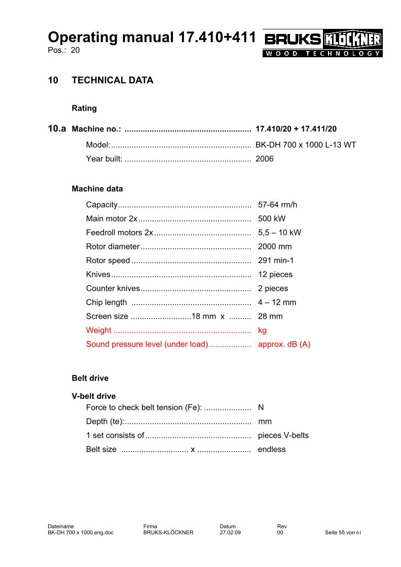
10 TECHNICAL DATA
Rating
10.a Machine no.: ........................................................ 17.410/20 + 17.411/20
Model:.............................................................. BK-DH 700 x 1000 L-13 WT
Year built: ........................................................ 2006
Machine data
Capacity........................................................... 57-64 rm/h
Main motor 2x.................................................. 500 kW
Feedroll motors 2x ........................................... 5,5 – 10 kW
Rotor diameter ................................................. 2000 mm
Rotor speed ..................................................... 291 min-1
Knives.............................................................. 12 pieces
Counter knives................................................. 2 pieces
Chip length ..................................................... 4 – 12 mm
Screen size ...........................18 mm x .......... 28 mm
Weight ............................................................. kg
Sound pressure level (under load)................... approx. dB (A)
Belt drive
V-belt drive
Force to check belt tension (Fe): ..................... N
Depth (te):........................................................ mm
1 set consists of ............................................... pieces V-belts
Belt size .............................. x ........................ endless

Operating manual 17.410+411 Pos.: 20
Dateiname Firma Datum Rev BK-DH 700 x 1000 eng.doc BRUKS-KLÖCKNER 27.02.09 00 Seite 56 von 61
Flat belt drive
Tension: .......................................................... 2 %
Belt width: ........................................................ 700 mm
Belt length:....................................................... 11000 mm endless
Belt type:.......................................................... GT 54 P GR/SCHW
Torque for fasteners
Bolted connections (all bolts grade 8.8) Bolt diameter Lubrication Torque M8 oiled 25 Nm
M10 " 50 Nm
M12 " 90 Nm
M16 " 210 Nm
M20 " 410 Nm
M24 " 700 Nm
Special bolts Clamping bolts for knives (Grade 10.9) Size Lubrication Torque M20 MoS2 - paste 450 Nm
M22 MoS2 - paste 600 Nm
Clamping bolts for bolted counter knives (Grade 10.9) Size Lubrication Torque M12 MoS2 - paste 100 Nm
M16 MoS2 - paste 230 Nm
M20 MoS2 - paste 450 Nm

Operating manual 17.410+411 Pos.: 20
Dateiname Firma Datum Rev BK-DH 700 x 1000 eng.doc BRUKS-KLÖCKNER 27.02.09 00 Seite 57 von 61
Pull screw for clamped anvil (Grade 8.8) Size Lubrication Torque
M16 MoS2 - paste 170 Nm
M20 MoS2 - paste 330 Nm
Set screw holding anvil carrier in place (Grade 10.9) Size Lubrication Torque
M16 MoS2 - paste 220 Nm
Spindle for wedge type knife clamping Size Lubrication Torque
M36 MoS2 - paste 330 Nm
Accumulator
Gas pressure p1 = ........................................... 16 bar
Oil pressure p3 = ............................................ 50 bar
Gear Motors
Gear motor upper feeding rolls
Type:........................................................................... R167 DV160L-F8/4TF
Design:........................................................................ M1
Gear motor lower infeed rolls
Type:........................................................................... R167 DV160L8/4TF
Design:........................................................................ M1
Gear motor belt drive
Type:........................................................................... FA 97 G DV132S8/4
Design:........................................................................ M1

Operating manual 17.410+411 Pos.: 20
Dateiname Firma Datum Rev BK-DH 700 x 1000 eng.doc BRUKS-KLÖCKNER 27.02.09 00 Seite 58 von 61
Couplings Coupling Product: .................................................
Type:......................................................
Coupling main motor – pulley Product: .................................................
Type:......................................................
Knives
Chipping knives
Dimensions: ....................... 565 mm x........ 28 mm x ......... 25 mm
knife angle: ......................... 26 degrees
Counter grind: ..................... 15 mm x.......... 6 degrees
Counter knives
Dimensions: ........................ 715 mm x........ 120 mm x ....... 40 mm

Operating manual 17.410+411 Pos.: 20
Dateiname Firma Datum Rev BK-DH 700 x 1000 eng.doc BRUKS-KLÖCKNER 27.02.09 00 Seite 59 von 61
11 KEEPING OF SPARE PARTS
Stock keeping of the most important spare- and wear parts on site is an important
precondition for the permanent functioning and readiness for operation of the
BRUKS-KLÖCKNER - drum chipper. We only accept responsibilities for original spare parts delivered by us. We draw your attention to the fact that we have tested and released original spare
parts and accessories which were not delivered by us. The fitting and/or use of such
products can under certain circumstances have negative effects to the prescribed
properties of the belt conveyor and for that reason impair actively and/or passively
the safety. For damages resulting from the use of non-original spare parts and ac-
cessories we exclude any responsibility and guarantee on the part of BRUKS-KLÖCKNER GmbH.
A list of recommended spare parts to be kept in stock can be obtained from us or
from one of our agents.
To order spare parts please use the spare part drawings and piece lists in the follow-
ing chapter.
For spare part orders please specify as follows:
Machine-No.:
Type:
Module/Group No.:
Part No.:
Required quantity:

Operating manual 17.410+411 Pos.: 20
Dateiname Firma Datum Rev BK-DH 700 x 1000 eng.doc BRUKS-KLÖCKNER 27.02.09 00 Seite 60 von 61
12 SPARE PART DRAWINGS AND LISTS

Operating manual 17.410+411 Pos.: 20
Dateiname Firma Datum Rev BK-DH 700 x 1000 eng.doc BRUKS-KLÖCKNER 27.02.09 00 Seite 61 von 61
13 APPENDIX

S-PLAN-E.XLS
Lubricants table
application spur wheel back geared motor / flat gear motor worm gear motor hydraulic plant rollingbearings chains
kind of grease mineral oil synthetic
oilsemi-fluid
grease
semi-fluidgrease
synthetic
syntheticoil
semi-fluidgrease
synthetichydraulic oil
Lithium su-ponifiedgrease basic
oil mineral
multi-purposegrease
temperature -5 ... +40 -15 ... +25 -25 ... +80 -20 ... +50 -35 ... +60 -25 ... +80 -35 ... +60 -15 ... +60 -7 ... +70 0 ... +80 +5 ... +90 -30 ... +60 -30 ... +60
ARAL DEGOLBG 220
DEGOLBG 100
DEGOLGS 220
ARALUBFDP 00
DEGOLGS 220
VITAMGF 22
VITAMGF 32
VITAMGF 46
VITAMGF 68
ARALUBHL 3
BP ENERGOLGR-XP220
ENERGOLGR-XP100
ENERGOLSG-XP220
HT-EP 00FG00-EP
ENER-GREASEGSF
ENERGOLSR-XP220
ENERGOLHL 22
ENERGOLHL 32
ENERGOLHL 46
ENERGOLHL 68
ENER-GREASELS 3
FINA GERAN 220 GERAN 220 HYDRAN 46
HYDRAN 46
HYDRAN 46
HYDRAN 46
DEA MEROPA220
MEROPA150
SYNLUBECLP220
GLIS-SANDOGF 1464
SYNLUBECLP 220
RANDO22
RANDO32
RANDO46
RANDO68
MULTI-FAKFL 30
MULTI-FAKEP 2
ESSO SPARTANEP 220
SPARTANEP 150
UMLAUF-ÖLS 220
FIBRAXEP 370 EGL 3818A
UMLAUF-ÖLS 220
SPINESSO22
NUTO32
NUTO46
NUTO68 H 443
MOBILMOBIL-GEAR630
MOBIL-GEAR629
GLYGOYLE30
MOBILEX44 RR 103 B
GLY-GOYLE30
VELOCITEOIL No. 10
DTE OILLIGHT
DTE OILMEDIUM
DTE OILHEAVYMEDIUM
Mehr-zweckfettBEACON 2
SHELL OMALAOEL 220
OMALAOEL 100
TIVELAOEL WB
Spezial-Getr.-FettH
TIVELACOM-POUND A
TIVELAOEL WB
ALVANIAR L3STAMINAEP2