David Theo Goldberg at the 2014 Open Badges Summit for Reconnected Learning

Website : www. aceengineeringpublications.com
Electrical Engineering(Volume - II)
(Electromagnetic Fields, Electrical Machines, Power Systems, Power Electronics,Electrical & Electronic Measurements, Engineering Mathematics, and General Aptitude)
1116 Expected Questions with Solutions
ACEEngineering Publications
(A Sister Concern of ACE Engineering Academy, Hyderabad)
Hyderabad | Delhi | Bhopal | Pune | Bhubaneswar | Bengaluru | Lucknow | Patna | Chennai | Vijayawada | Visakhapatnam | Tirupati | Kukatpally | Kolkata
ACE is the leading institute for coaching in ESE, GATE & PSUsH O: Sree Sindhi Guru Sangat Sabha Association, # 4-1-1236/1/A, King Koti, Abids, Hyderabad-500001.
Ph: 040-23234418 / 19 / 20 / 21, 040 - 24750437
7 All India 1st Ranks in ESE43 All India 1st Ranks in GATE
GATEPRACTICE BOOKLET
Bits & Bytes

Copyright © ACE Engineering Publications 2018
All rights reserved.
Published at :
Authors : Subject experts of ACE Engineering Academy, Hyderabad
While every effort has been made to avoid any mistake or omission, the publishers do not owe any responsibility for any damage or loss to any person on account of error or omission in this publication. Mistakes if any may be brought to the notice of the publishers, for further corrections in forthcoming editions, to the following Email-id. Email : [email protected]
First Edition : 2011Revised Edition : 2018
Printed at :Karshak Art Printers,Hyderabad.
Price : `. 450/-ISBN : 978-1-946581-91-4
ACE Engineering Publications
Sree Sindhi Guru Sangat Sabha Association,# 4-1-1236/1/A, King Koti, Abids, Hyderabad – 500001, Telangana, India.Phones : 040- 23234419 / 20 / 21 www.aceenggacademy.comEmail: [email protected] [email protected]
No part of this publication may be reproduced, stored in a retrieval system, or transmitted, in any form or by any means, electronic, mechanical, photocopying, digital, recording or otherwise, without the prior permission of the publishers.

ForewordGATE in Electrical Engineering
GATE PRACTICE BOOKLET (B B )
VOLUME II
Dear Students,
Solutions of all previous GATE Questions are already available. Every year about 20% of questions will have repetitive nature. However, rest of the questions are from untapped areas (never asked areas) and few from Previous Engineering Services & Civil Services Questions. Keeping this in view, possible questions are prepared in various subjects (chapter wise) along with their hints/solutions. The student is advised to practice the questions systematically so that their chances of getting high score in GATE Exam will increase.
The student is advised to solve the problems without referring to the solutions. The student has to analyze the given question carefully, identify the concept on which the question is framed, recall the relevant equations, fi nd out the desired answer, verify the answer with the fi nal key such as (a), (b), (c), (d), then go through the hints to clarify his answer. This will help to face numerical answer questions better. The student is advised to have a standard text book ready for reference to strengthen the related concepts, if necessary. The student is advised not to write the solution steps in the space around the question. By doing so, he loses an opportunity of effective revision.
As observed in the GATE Exam, number of sets may be possible, being online exams. Hence, don’t skip any subject. All are equally important.It is believed that this book is a Valuable aid to the students appearing for competitive exams like ESE, JTO, DRDO, ISRO and Other PSU’s. This book can also be used by fresh Teachers in Engineering in improving their Concepts.
With best wishes to all those who wish to go through the following pages.
Y.V. Gopala Krishna Murthy,M Tech. MIE,
Chairman & Managing Director,ACE Engineering Academy,
ACE Engineering Publications.

Electrical Engineering GATE PRACTICE BOOKLET (B B )
VOLUME II
MAIN INDEX
S.No. Name of the Subject Page No.
1 Electromagnetic Fields 01 – 302 Electrical Machines 31 – 1343 Power Systems 135 – 2604 Power Electronics 261 – 3345 Electrical & Electronic Measurements 335 – 3846 Engineering Mathematics 385 – 4487 General Aptitude (Numerical & Verbal Ability) 449 – 484

Hyderabad|Delhi|Bhopal|Pune|Bhubaneswar| Lucknow|Patna|Bengaluru|Chennai|Vijayawada|Vizag |Tirupati | Kukatpally | Kolkata ACE Engineering Publications
01. The voltage regulation of a 10 kVA single
phase transformer are 4.6 % and –2.6 % at 0.8 p.f. Lag and 0.8 p.f. Lead, respectively. The iron loss is 75 W. The maximum efficiency at 0.8 p.f. Lag is
(a) 96.72 % (b) 97.64% (c) 98.2 % (d) 96.2% 02. A certain transformer operating at a
particular frequency has equal hysteresis and eddy current losses. If the voltage and frequency are doubled, the ratio of the hysteresis and eddy current losses is
(a) 1 : 1 (b) 1 : 2 (c) 2 : 1 (d) 1 : 4 03. A 100/ 10V, 50 VA two winding
transformer is converted into a 100 / 110 V, auto-transformer. Then, its rating is
(a) 100 VA (b) 110 VA (c) 550 VA (d) 500 VA 04. If the applied voltage of a transformer with
an unsaturated magnetic circuit is increased by 50 % and the frequency is reduced to 50%, the maximum flux density will
(a) change to 3.0 times the original value (b) change to 1.4 times the original value (c) change to 0.5 times the original value (d) remain unaltered
05. For two transformers operating in parallel, for the load to be shared in proportion to the capacities. (a) the ohmic impedances must be
proportional to kVA ratings (b) p.u. impedances on their own bases must
be the same (c) p.u. impedances on a common base must
be the same (d) either (b) or (c)
06. With scott-connected transformers supplying balanced loads, (a) Teaser primary current = Main primary
current (b) Teaser primary current > Main primary
current (c) 3-phase line currents are equal, but not
balanced (d) 3-phase line currents are equal and
balanced
07. In a hundred turn coil, if the flux through each turn is (2 t4 – t3 – 2 t) m webers, the magnitude of the induced emf in the coil at t = 2 sec
(a) 0.50 mV (b) 5.0 mV (c) 50 mV (d) 5.0 V
08. Two similar 250 kVA, single phase transformers gave the following results when tested by back to back method: Mains wattmeter, W1 = 5.0 kW Primary series circuit wattmeter, W2 = 7.5 kW (at full load
TransformersChapter1

:34: ElectricalMachines
Hyderabad|Delhi|Bhopal|Pune|Bhubaneswar| Lucknow|Patna|Bengaluru|Chennai|Vijayawada|Vizag |Tirupati | Kukatpally | Kolkata ACE Engineering Publications
current). The individual transformer efficiency at 75% full load and 0.8 p.f. load will be nearly
(a) 97% (b) 95% (c) 93% (d) 90% 09. 1- transformer has hysteresis loss of 200W
and eddy current loss of 100W at 50Hz operation. Its core losses at 60Hz operation will be
(a) 432W (b) 408W (c) 384W (d) 360W 10. A 1- transformer has percentage regulation
of 4% and 4.4% for lagging power factor of 0.8 and 0.6 respectively. The lagging p.f at which the full load regulation is maximum will be
(a) 0.38 (b) 0.48 (c) 0.556 (d) 0.447 11. A single phase transformer has rating of
15 kVA, 600/120 V. It is reconnected as an auto transformer to supply 720V from 600V primary source. The maximum load it can be supplied with is
(a) 90kVA (b) 18kVA (c) 15kVA (d) 12kVA 12. A 50 Hz, single phase transformer draws a
short circuit current of 30A at 0.2 p.f. lag when connected to 16V, 50 Hz source. The short circuit current, when same transformer is energized from 16V, 25Hz source is
(a) 39.73A (b) 48.36A (c) 56.65A (d) 62.83A
13. A 5 kV, 25 Hz, single phase transformer has copper, hysteresis and eddy current losses of 1.4, 0.6, 0.5 percent of full load output. If operated on 10 kV, 50 Hz system, the percentage copper, hysteresis and eddy current losses, with same current in the windings are
(a) 1.7, 0.6, 0.5 (b) 1.4, 1.2, 2.0 (c) 0.7, 0.6, 1.0 (d) 1.4, 0.6, 1.0
14. Read the following statements. Choose the correct combination of true statements from the following (P) Eddy current losses in a transformer
depend on both voltage and frequency. (Q) Hysteresis losses in a transformer
depend upon frequency alone (R) To control the terminal voltage,
transformer is provided with taps on HV side at the middle
(S) Transformers of different kVA ratings can be operated in parallel provided their equivalent leakage impedances are inversely proportional to their respective kVA ratings.
(a) P, R (b) Q, S (c) Q, R (d) R, S 15. A 100 kVA, 50Hz, 440/11000V, 1-
transformer has an efficiency of 98.5%, when supplying full load current at 0.8 pf and an efficiency of 99%, when supplying half full load current at unity pf. the maximum efficiency will be attained at a load current of

:41: Transformers
Hyderabad|Delhi|Bhopal|Pune|Bhubaneswar| Lucknow|Patna|Bengaluru|Chennai|Vijayawada|Vizag |Tirupati | Kukatpally | Kolkata ACE Engineering Publications
Solutions 01. Ans: (b)
Sol: Voltage regulation at 0.8 pf lag, %6.46.0X%8.0)R(% ……. (1)
Voltage regulation at 0.8 p.f lead, %6.26.0X%8.0)R(% ……. (2)
By solving these two equations %R = 1.25 % X = 6 iron losses = 75W %R = full load copper losses
100
25.18.0k10 100W
At max. efficiency,
75)100(x2
866.043x
100150866.08.0k10
866.08.0k10
= 97.88% 02. Ans: (b)
Sol: For a given transformer, hysteresis loss
Wh = Kh nmBf and eddy – current loss We =
Ke f2 2mB where Kh and Ke are constants for a
given transformer and other symbols have usual meanings.
When voltage and frequency are both doubled, V/f remains constant and Bm the maximum core flux density remains constant. So
Wh = fK1h and We = 21
e fK .
At the original frequency f1, Wh = 11h fK
We = .fK 21
1e and 1
1h fK = .fK 2
11e
Hence .fKK 11e
1h
At frequency 2f1, new hysterisis loss
= .f2fK)f2(K 111e1
1h
New eddy – current loss
= .fK4)f2(K 21
1e
21
1e
.21
fK4fK2
losscurrenteddyNewlosshysterisisNew
21
1e
21
1e
03. Ans: (c)
Sol:
Rated LV winding current = .51050
A I
cannot exceed 5A in magnitude. So load current (rated) = 5A, load voltage (rated) = 110V. Rating of the autotransformer = 110 5 = 550 VA.
04. Ans: (a)
Sol: We have V E = 4.44 NAC f Bm1. V is increased to 1.5V. f is decreased to 0.5f.
Then; 1.5 V = 4.44 NAC (0.5f) Bm2.
load
+ 1000V
+
11000 V
+
I
10000
+
V

:42: ElectricalMachines
Hyderabad|Delhi|Bhopal|Pune|Bhubaneswar| Lucknow|Patna|Bengaluru|Chennai|Vijayawada|Vizag |Tirupati | Kukatpally | Kolkata ACE Engineering Publications
+
+ – + –
I
E E
V
load
1 2
1I 2I 1Z 2Z
3V
fNA44.4f)5.0(NA44.4
V5.1BB C
C1m
2m .
Maximum core flux density will change to 3 times original value.
05. Ans: (b)
Sol:
a) Ratings: Transformer 1: E volts, S1VA, Transformer 2: E volts, S2VA.
b) It is desired that 2
1
2
1
SS
II
c) Now, VZIEZIE 2211
2211 ZIZI
1
2
2
1
ZZ
II (magnitudes).
Z1 in p.u to its own base, E & S1 = 211
ESZ p.u
Z2 in p.u to its own base, E & S2 = 222
ESZ p.u
If these p.u values are equal, Z1S1 = Z2S2;
2
1
1
2
2
1
II
ZZ
SS
.
Each transformer shares a load proportional to its capacity.
Note: P.u impedances on a common base,
say E & S1, are 211
ESZ p.u & 2
12E
SZ p.u.
If these are equal, Z1 = Z2; I1 = I2; & they do not share loads proportional to their kVA ratings.
06. Ans: (d)
Sol:
KVL,V00 = ysRS VV .
oys SB
VV V 1202
V00 = oRs
VV 1202
ooRS 120
2V0VV
2
2RS
V 3V V V4 2
.
oRS 30V
23V .
12NV3 N
2
o o3 V 30 V 302
For simplicity, assume loads to be balanced and purely resistive. Load currents are I30o & 120o as shown on the 3-phase side, let the currents be as shown. From transformer property,
V-1200
Y
B
+
+
YI
BI
2
N
V00 RsV
+
YSV +
2
N
S +
SBV
N2
3
I-1200
+
V-1200
N
R
+
R
2
N 012V V 30
1 RI
R

:43: Transformers
Hyderabad|Delhi|Bhopal|Pune|Bhubaneswar| Lucknow|Patna|Bengaluru|Chennai|Vijayawada|Vizag |Tirupati | Kukatpally | Kolkata ACE Engineering Publications
RNI I 303 N
2
= .A30I3
2 o
We have Y BN NI I I 120 N2 2
.
Which gives oBY 120I2II .
Also, R Y BI I I 0
oY B R
2I I I I 303
0 oY
22 I 2I 120 I 303
0Y
II I 120 303
oY 150I
32I
We can similarly show that
oB 90I
32I
07. Ans: (d)
Sol: Flux through each turn = (2t4 t32t)103 Wb
Flux linkages of the coil, (t) = 100(2t4 t3 2t) 103 Wb-turns
Induced emf = dt
)t(d
= 100(8t3 3t2 2)103 Volts. At t = 2, e(t) = 100(64 12 2) 10- = 5 V 08. Ans: (a)
Sol: Core loss of each transformer = 2
5000
= 2500 W
Copper losses of each transformer at full
load current = 2
7500 = 3750 W
At 75% full load, copper loss of each
transformer = 2
10075
3750 = 2109.4 W
Total loss of each transformer = 4609.4 W Power output at 75% full load, 0.8pf = 250 103 75.0 0.8 = 150,000 W
Efficiency = 4.154609
000,150 = 97%
09. Ans: (c)
Sol: Wh = Kh f nmB We = Ke f2 2
mB
Assume max. flux density in core, Bm is constant.
At 50 Hz, Wh = 50 KhnmB = 200 W
We = 2500 Ke2mB = 100 W
At 60 Hz, Wh = 60 kh nmB
= 2406050200
W
We = 3600 Ke 2mB
= 36002500100
= 144 W
At 60Hz, core losses = 240 + 144 = 384 W 10. Ans: (d)
Sol: Regulation at 0.8 lagging power factor % R(0.8) + % X(0.6) = 4%. Regulation at 0.6 lagging power factor % R(0.6) + % X(0.8) = 4.4%. By solving these two equations

:44: ElectricalMachines
Hyderabad|Delhi|Bhopal|Pune|Bhubaneswar| Lucknow|Patna|Bengaluru|Chennai|Vijayawada|Vizag |Tirupati | Kukatpally | Kolkata ACE Engineering Publications
%R = 2 % X = 4
447.0Z%R%cos
11. Ans: (a)
Sol: The transformer resistances and leakage reactance are neglected, since the data is not given. (The transformer is considered as ideal).
Magnitude of maximum load current
without exceeding ratings A125120
15000
Max. kVA load that can be supplied without overloading on transformer
kVA9010000
720125
12. Ans: (c)
Sol: With 25 Hz; leakage reactance becomes X, whereas its value is 2X at 50 Hz.
50Hz: 30x4r
1622
2844.0x4r 22 ....(1)
1 1 o2xTan cos 0.2 78.46r
9.4rx2 r9.4x2
22 r24x4
From equation (1) 25r2 = 0.2844
0114.0r2
r = 0.1067 2x = 0 .523 x = 0.2615 At 25Hz; r = 0.1067 Leakage reactance = 0.2615 Now the short circuit current
=22 2615.01067.0
16
= 56.7 A
13. Ans: (c)
Sol: Ratings 5 kV; 25 Hz. At full load, let copper losses, hysteresis losses and eddy current losses be Wcu, Wh, We watts respectively.
It is operated at 10 kV, 50 Hz. Since V/f ratio is kept constant, maximum core flux-density is constant. So hysteresis losses are proportional to frequency and eddy current losses are proportional to square of frequency.
New hysteresis loss = 2 Wh New eddy current loss = 4 We Copper losses: At 10 kV; current is still
assume at the rated value, so that power output doubles. Copper losses remain the same in watts, so that as a percentage of power output; copper losses become 0.7%. As a percentage of the new power output hysterisis loss remains the same at 0.6%, while eddy current losses become 20.5=1% of near output. 0.7, 0.6 and 1 is the answer.
+
–
6000V 600 0oV
+
–
+ 1200V –
720 0oV
1200
–
+

:45: Transformers
Hyderabad|Delhi|Bhopal|Pune|Bhubaneswar| Lucknow|Patna|Bengaluru|Chennai|Vijayawada|Vizag |Tirupati | Kukatpally | Kolkata ACE Engineering Publications
Rc jxm
jx r
Voltage supply
0I +
14. Ans: (a)
Sol: P: Eddy current loss = Kef2 2mB . The
maximum core flux density depends upon
the voltage and frequency. (P) is true. Q: Hysterisis loss also depends on frequency
and voltage (Q) is false. R: Transformer is provided with tappings to
control the voltage (usually at the middle). (R) is true
S: VZIEZIE 2211 . (see fig)
from which 1
2
2
1
ZZ
II
If then;2ofkVArated1ofkVArated
2ofcurrentrated1ofcurrentrated
ZZ
1
2
I1 and I2 will be proportional to their ratings. But even otherwise, they can be operated in parallel. Only they will not share the load according to their ratings. S is false. P&R are true.
15. Ans: (a)
Sol: Losses at full load and 0.8 pf (lag or lead is immaterial in loss calculations)
= (1001030.8)
985.0985.01 = 1218W
= Constant core loss We+copper loss Wcu
Losses at half full load and upf
= 50599.0
99.012
10100 3
W
= Wc + copper loss Wcuhfl
But Wcuhfl = lcufW41
. Hence core loss = 267
W. Full load copper loss Wcufl = 951 W. If maximum efficiency occurs at x(full
load), x2(951) = 267. x = 0.53 Full load current (on lv side)
= .A3.227440
10100 3
Current at which maximum efficiency occurs = 0.53227.3 = 120.5 A
16. Ans: (c)
Sol: The no-load (open-circuit) equivalent circuit is as shown.
(Symbols have the usual meanings) Neglecting effect of temperature changes, r,
is constant. Neglecting saturation at constant frequency, x, & x m are constant. With an
increase in voltage while frequency is kept constant, the maximum flux density in the core increases. Hysterisis losses and eddy current losses increase. R c decreases. So I0
increases. Thus, no load current increases,
+
+– +–
1Z 2Z
E
E
V 1I
I
2I

Hyderabad|Delhi|Bhopal|Pune|Bhubaneswar| Lucknow|Patna|Bengaluru|Chennai|Vijayawada|Vizag |Tirupati | Kukatpally | Kolkata ACE Engineering Publications
01. Calculate the GMR of each of the
unconventional conductors shown in figure in terms of the radius r of the individual strand.
(a) 0.95 r (b) 2.19 r (c) 1.72 r (d) 4.95 r 02. Calculate the GMR of each of the
unconventional conductors shown in figure in terms of the radius r of the individual strand.
(a) 1.67 r (b) 2.89 r (c) 0.96 r (d) none 03. Calculate the GMR of each of the
unconventional conductors shown in figure in terms of the radius r of the individual strand.
(a) 2.10 r (b) 3.10 r (c) 1.01 r (d) 0.56 r
04. Calculate the inductance / km / phase of a single circuit using two bundle conductors/phase as shown below. The diameter of each conductor is 5 cm
(a) 0.807 mH/km (b) 0.906 mH/km
(c) 0.505 mH/km (d) 1.02 mH/km
05. Find self GMD and GMD of the following
bundle conductor system in which radius of conductor r = 2 cm, all the phases are identical to each other.
(a) 7.893 cm, 8 m (b) 6 cm, 8 m
(c) 7.893 cm, 6 m (d) 8 cm, 8 m
a a1 b1 c1
c b
6.5m 6.5m
40cm
Transmission&DistributionChapter2
Y1
8 m
R1 R2
8 m
40 cm
40 cm
8 m
B1 B2
Y2

:143: Transmission&Distribution
Hyderabad|Delhi|Bhopal|Pune|Bhubaneswar| Lucknow|Patna|Bengaluru|Chennai|Vijayawada|Vizag |Tirupati | Kukatpally | Kolkata ACE Engineering Publications
06. A shunt reactor at 100 MVAr is operated at 98% of its rated voltage and at 96% of its rated frequency. The reactive power absorbed by the reactor is
(a) 98MVAr (b) 104.02 MVAr (c) 96.04 MVAr (d) 100.04 MVAr
07. The above circuit model represents a 3
phase transmission line with active (synchronous machine) at each end, and with a ground return circuit. If Va, Vb, Vc, are regarded as zero, the circuit represents a three-star connected impedances with return through Zn. Hence we have,
VA – Va = VAa Voltage drop in Za and Zn VB – Vb = VBb Voltage drop in Zb and Zn VC – Vc = VCc Voltage drop in Zc and Zn
Which one of the following is the correct impedance matrix for calculation of voltage drop
(a)
c
b
a
Z000Z000Z
(b)
cnn
nbn
nna
ZZZZZZZZZ
(c)
ncnn
nnbn
nnna
ZZZZZZZZZZZZ
(d)
ncnn
nnbn
nnna
ZZZZZZZZZZZZ
08. A single phase 275 kV transmission line has the following line constants
A = 0.85 5 B = 200 75 The transmission line is loaded by a 150
MW UPF load. The voltage profile at each end is maintained at 275 kV. The rating of the compensation equipment is
(a) 17.85 MVAR (b) 22.3 MVAR (c) 27.56 MVAR (d) 13.757 MVAR 09. Insulator consisting of 3 discs, ground
capacitance is 1 F and capacitance of disc near ground is 10 F. In capacitance grading find the value of capacitance of second disc.
(a) 12F (b) 14F (c) 11F (d) 13F 10. A Shunt capacitor is connected across a bus
bar when the voltage is 0.9 pu and a shunt
In=Ia+Ib+Ic
Ia
Ib Ic
Za
Zb
Zc Va
Vb Vc
Zn
Va Vb
Vc
cg
cg
Ig I1
I2
C3
C2
C1 V
V
V
Conductor

:153: Transmission&Distribution
Hyderabad|Delhi|Bhopal|Pune|Bhubaneswar| Lucknow|Patna|Bengaluru|Chennai|Vijayawada|Vizag |Tirupati | Kukatpally | Kolkata ACE Engineering Publications
Solutions
66. Two conductors of a single phase line each of 2.5 cm diameter are arranged in a vertical plane with one conductor mounted 1.5m above the other. A second identical line is mounted at the same height as the first and space horizontally 0.5m apart from it, the two upper and lower conductors are connected in parallel. The conductors are 15 meters above the ground, then the inductance per km of the resulting double circuit line_______ mH/km.
01. Ans: (c)
Sol: Given data: Dab = 2 r, Dac = 2r
Dad = 22 )r2()r2( = 2r8 = 2 2 r
GMR = 4 r22r2r2r7788.0
= 1.723 r 02. Ans: (a)
Sol: Given data: Dab = 2r, Dac = 2r Dbd = 2r. Dcd = 2r
Dad = 22 r)r2(2 = r32
GMRa = 4 r32r2r2r7788.0 = 1.81 r
GMRb = 4 r2r2r2r7788.0 = 1.58 r
GMRc = 4 r2r2r2r7788.0 = 1.58 r
GMRd = 4 r32r2r2r7788.0 = 1.81 r
GMR= 4 )r51.1()r58.1()r58.1()r81.1(
= 1.69 r. 03. Ans: (a)
Sol: Given data: Dab = 2r, Dac = 2r, Dad = 4r, Daf = 4r
Dae = r32 GMRa = 6
afaeadacab )r7788.0(DDDDD
= 6 r7788.0r32r4r4r2r2
= 2.359 r GMRb 6
bfbebcbdba 0.7788)DDDD(D
6 0.7788)×r 23 ×2r ×2r ×2r ×(2r
= 1.87 r
GMRc = 6cfcecdcbca r7788.0DDDDD
= 6 r7788.0r2r2r32r2r2
= 1.87r
GMRd = 6dfdedcdbda r7788.0DDDDD
= 6 r7788.0r4r2r32r2r4
a
b c
d
a
b c
d e f
a b
c d

:154: PowerSystems
Hyderabad|Delhi|Bhopal|Pune|Bhubaneswar| Lucknow|Patna|Bengaluru|Chennai|Vijayawada|Vizag |Tirupati | Kukatpally | Kolkata ACE Engineering Publications
= 2.359 r
GMRe = 6efedecebea r7788.0DDDDD
= 6 r07788r2r2r2r2r32
= 1.87 r
GMRf = 6fa fb fc fd feD D D D D 0.7788r
= 2.359 r
GMR= 6fedcba GMRGMRGMRGMRGMRGMR
= 6 33 )r87.1()r359.2(
= 2.10 r 04. Ans: (b)
Sol: Given data: d = 5cm; r = 2.5cm = 2.5102m Dab = 6.5m, Dbc = 6.5m Dac = Dca = 13m
3cabcab dddD.M.G
3 135.65.6 = 8.189 m Self GMD can be calculated by using this
formula
aaaa DDGMR
22 1040105.27788.0 = 0.08825
km/mHGMRGMDln2.0L
08825.0189.8ln2.0
km/mH906.0
05. Ans: (a)
Sol: Self GMD
= 3R y Bself GMD .self GMD .self GMD
= self GMDR (All phases are identical)
= 11r s
= 0.7788 2 40 = 7.893 cm
GMD = 3RY YB RBD D D
(By neglect spaces between sub conductors)
= 3 8 8 8 = 8 m. 06. Ans: (d)
Sol: Given data: Q = 100MVAr
Q = L
V
2
Where, V = 0.98V, = 0.96
Q = 10096.0
)98.0( 2
= 100.04MVAr 07. Ans: (d)
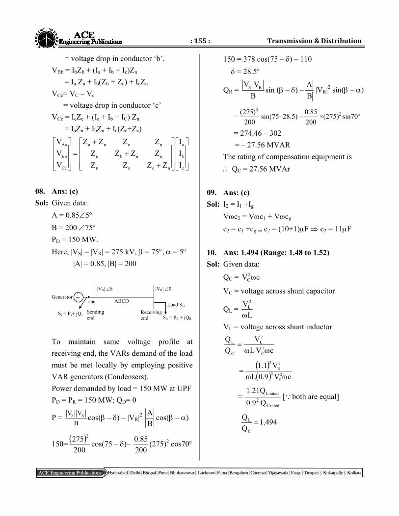
Sol: Given data: Voltage drop in conductor ‘a’ = VA – Va = VAa
VAa = IaZa + (Ia + Ib + Ic) Zn = Ia (Za + Zn) + IbZn + IcZn VBb = VB – Vb
a a b c
c b
6.5m 6.5m
40cm
:155: Transmission&Distribution
Hyderabad|Delhi|Bhopal|Pune|Bhubaneswar| Lucknow|Patna|Bengaluru|Chennai|Vijayawada|Vizag |Tirupati | Kukatpally | Kolkata ACE Engineering Publications
= voltage drop in conductor ‘b’. VBb = IbZb + (Ia + Ib + Ic)Zn = Ia Zn + Ib(Zb + Zn) + IcZn VCc= VC – Vc = voltage drop in conductor ‘c’ VCc = IcZc + (Ia + Ib + IC) Zn = IaZn + IbZn + Ic(Zn+Zc)
c
b
a
ncnn
nnbn
nnna
Cc
Bb
Aa
III
ZZZZZZZZZZZZ
VVV
08. Ans: (c)
Sol: Given data: A = 0.855 B = 200 75 PD = 150 MW. Here, |VS| = |VR| = 275 kV, = 75, = 5 |A| = 0.85, |B| = 200
To maintain same voltage profile at receiving end, the VARs demand of the load must be met locally by employing positive VAR generators (Condensers).
Power demanded by load = 150 MW at UPF PD = PR = 150 MW; QD= 0
P = S RV VB
cos( – ) – |VR|2 BA cos( – )
150= 200275 2
cos(75 – )– 200
85.0 (275)2 cos70
150 = 378 cos(75 – ) – 110 = 28.5
QR = BVV RS sin ( – ) –
BA
|VR|2 sin( – )
=200
)275( 2
sin(75–28.5) –200
85.0 ×(275)2 sin70
= 274.46 – 302 = – 27.56 MVAR The rating of compensation equipment is QC = 27.56 MVAr 09. Ans: (c)
Sol: I2 = I1 +Ig Vc2 = Vc1 + Vcg c2 = c1 +cg c2 = (10+1)F c2 = 11F
10. Ans: 1.494 (Range: 1.48 to 1.52)
Sol: Given data:
QC = cV2C
VC = voltage across shunt capacitor
QL = L
V2L
VL = voltage across shunt inductor
cVL
VQQ
2C
2L
C
L
cV9.0L
V1.12R
2
2R
2
= ratedC
2ratedL
Q9.0Q21.1
[both are equal]
494.1QQ
C
L
Sending end
Receiving end
Load SD
SR = PR + jQR Ss = Ps+ jQs
Generator |VR| 0 |VS|
ABCD