opamp application, Bistable, astable and monostable multivibrator, IC-555 timer

BISTABLE MULTIVIBRATORLECTURE-4TDC PART I
PAPER II (GROUP- B)CHAPTER 3
By MINAKSHIASSISTANT PROFESSOR (GUEST
FACULTY)Department of ElectronicsLANGAT SINGH COLLEGE,
MUZAFFARPUR

Bistable Multivibrator have two stablestates and maintain a given output stateindefinitely unless an external trigger isapplied forcing it to change state. Thus abistable multivibrator requires twoexternal trigger pulses before it returnsback to its original state. To change thebistable multivibrator from one state tothe other, the bistable circuit requiresa suitable trigger pulse and to gothrough a full cycle, two triggeringpulses, one for each stage are required.
It is more commonly named or termed
as “flip flop”. It relates to the actual
operation of the device, as it “flips” into
one logic state, remains there and then
changes or “flops” back into its first
original state. Bistable multivibrator can
be designed using transistors or
operational amplifiers or 555 timer ICS
along with passive components, the
registers.
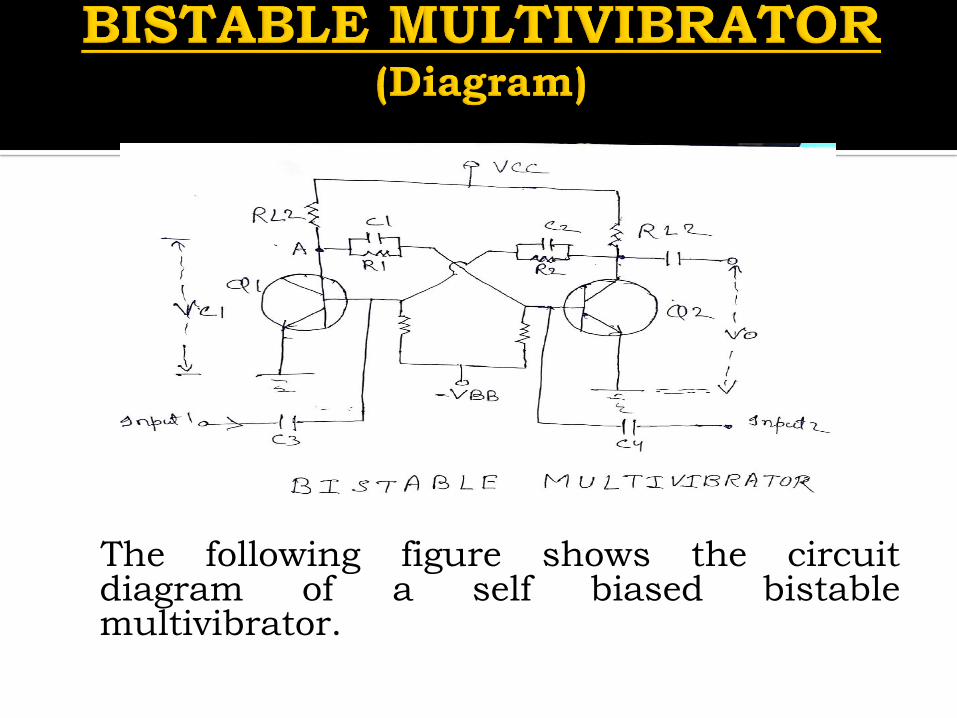
The following figure shows the circuitdiagram of a self biased bistablemultivibrator.

Two similar transistors Q1 and Q2
with load registers RL1 and RL2 are
connected in feedback to one another.
The base registers R3 and R4 are
joined to a common source – VBB.
The feedback resistors R1 and R2 are
shunted by capacitors C1 and C2
known as commutating capacitors.
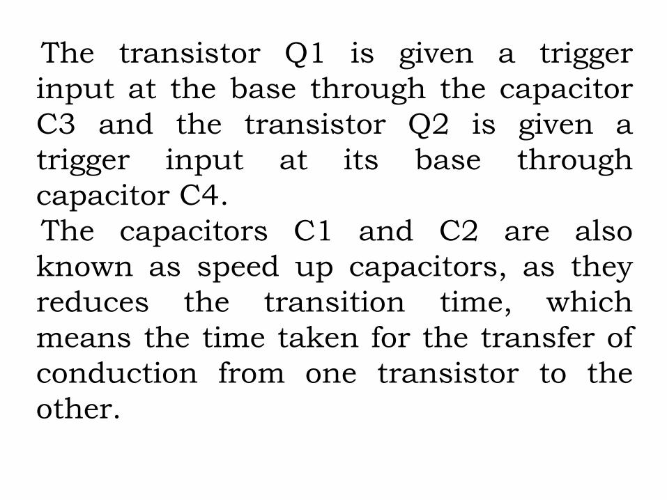
The transistor Q1 is given a trigger
input at the base through the capacitor
C3 and the transistor Q2 is given a
trigger input at its base through
capacitor C4.
The capacitors C1 and C2 are also
known as speed up capacitors, as they
reduces the transition time, which
means the time taken for the transfer of
conduction from one transistor to the
other.
When the circuit is switched on, due to somecircuit imbalances transistor Q1 getsswitched on, while the transistor Q2 getsswitched off. This is a stable state of thebistable multivibrator.By applying a negative trigger at the base oftransistor Q1 or by applying a positive triggerpulse at the base of transistor Q2, this stablestate is unaltered. So, let us understand thisby considering a negative pulse at the base oftransistor Q1. As a result, the collectorvoltage increases which forward biases thetransistor Q2.
The collector current of Q2 as applied at
the base of Q1, reverse biases Q1 and
this cumulative action, makes the
transistor Q1 OFF and the transistor Q2
ON. This is another stable state of the
multivibrator.
Now, if this stable state has to be
changed again then either a negative
trigger pulse at transistor Q2 or a
positive trigger pulse at transistor Q1 is
applied.
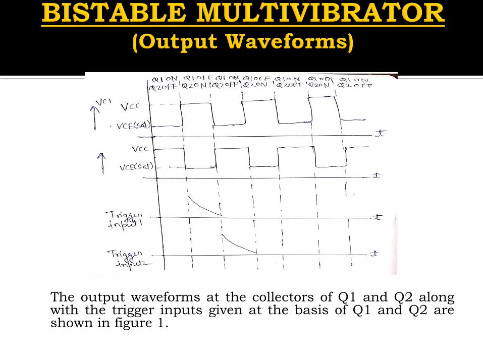
The output waveforms at the collectors of Q1 and Q2 alongwith the trigger inputs given at the basis of Q1 and Q2 areshown in figure 1.

Bistable multivibrator has manyapplications producing a set-reset, SR flip-flop circuit for use in counting circuits, oras a one bit memory storage device in acomputer . Other applications of bistableflip-flop include frequency divider becausethe output pulses have a frequency that areexactly one half that of the trigger inputpulse frequency due to the changing statefrom a single input pulse. In other wordsthe circuit produces frequency division as itnow divides the input frequency by a factorof two.
ADVANTAGES➢ It has the ability to store previousoutput until no any iutput trigger isprovided.
➢ The circuit design is not complex.DISADVANTAGES
➢Every time in order to have transitionfrom one state to another, triggeringpulse is required.
➢ It is somewhat costly than a stable andmonostable multivibrator.