BioNomadix Logger User Manual - BIOPAC
28
Doc90.v3 BioNomadix Logger User Manual Wearable Data Logging System for use with BioNomadix Transmitters and AcqKnowledge Software For Life Science Research Applications 42 Aero Camino, Goleta, CA 93117 Tel (805) 685-0066, Fax (805) 685-0067 ™
Transcript of BioNomadix Logger User Manual - BIOPAC
Doc90.v3
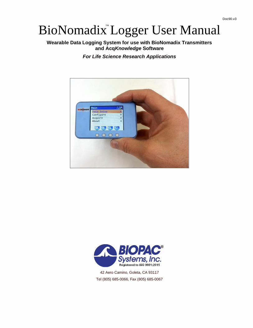
BioNomadix Logger User Manual
Wearable Data Logging System for use with BioNomadix Transmitters and AcqKnowledge Software
For Life Science Research Applications
42 Aero Camino, Goleta, CA 93117
Tel (805) 685-0066, Fax (805) 685-0067
™

BioNomadix Logger™ User Guide Page 2 of 28
WWW.BIOPAC.COM 10.8.2020
WWW.BIOPAC.COM
TABLE OF CONTENTS
System Overview ..................................................................................................................................................................... 3 How to Use This Manual................................................................................................................................................... 3 What is the BioNomadix Logger? ..................................................................................................................................... 3 BioNomadix Logger vs. Standard BioNomadix Transmitter-Receiver Pairs ....................................................................... 3 Included Components ....................................................................................................................................................... 3 Logger Battery .................................................................................................................................................................. 3 Logger Interface and Button Controls ................................................................................................................................ 4 Button Icons ..................................................................................................................................................................... 4 Charging and Powering on the Logger ............................................................................................................................... 4 Sleep Mode and Automatic Power-Off .............................................................................................................................. 5 Resetting the Logger ......................................................................................................................................................... 5 The Main Screen ............................................................................................................................................................... 5 Data Setup Options ........................................................................................................................................................... 5 Summary Screen Status and Warnings............................................................................................................................... 6 Using the Internal Accelerometer ...................................................................................................................................... 7 Tap Mode ......................................................................................................................................................................... 8 Accelerometer Assisted Synchronization ........................................................................................................................... 9 Pairing the Logger with a BioNomadix Transmitter ........................................................................................................... 9 Unpairing the Logger from a BioNomadix Transmitter .................................................................................................... 10 Paired Transmitter Menus ............................................................................................................................................... 10 Transmitter Options ........................................................................................................................................................ 10 Previewing Data ............................................................................................................................................................. 11 Choosing an Acquisition Rate ......................................................................................................................................... 11 Setting an Acquisition Length ......................................................................................................................................... 11 Starting an Acquisition Manually .................................................................................................................................... 12 Starting an Acquisition at a Preset Time .......................................................................................................................... 12 Preflight Setting .............................................................................................................................................................. 13 Checking for RF Interference during an Acquisition ........................................................................................................ 14 Using Multiple Loggers in Close Proximity ..................................................................................................................... 14 Optimizing Physical Configuration for Best Recordings .................................................................................................. 14 Placing Event Markers during an Acquisition .................................................................................................................. 15 Manually Stopping an Acquisition................................................................................................................................... 15 Adding an Audio Note .................................................................................................................................................... 15 Configure Menu .............................................................................................................................................................. 15 Setting the Date and Time ............................................................................................................................................... 16 Time Zone Adjustment ................................................................................................................................................... 17 Daylight Savings Time Adjustment ................................................................................................................................. 18 Configuring the Microphone ........................................................................................................................................... 19 Lock Screen .................................................................................................................................................................... 19 Setting other Configuration Options ................................................................................................................................ 19 Return to Main Screen Shortcut ....................................................................................................................................... 19 Common “Options” Shortcut ........................................................................................................................................... 20 Importing Logged Data into AcqKnowledge.................................................................................................................... 21 AcqKnowledge Menu Logger Options ............................................................................................................................ 22 Import Logs from Disk Option ........................................................................................................................................ 23 BioNomadix Logger User Alarms ................................................................................................................................... 23 Setting Up a User Alarm ................................................................................................................................................. 24 Reviewing Imported Logger Events and Audio Notes ...................................................................................................... 24 Supported Transmitter Data............................................................................................................................................. 25 BioNomadix Logger Specifications ................................................................................................................................. 25 Logger Troubleshooting .................................................................................................................................................. 26
Intended Use .......................................................................................................................................................................... 28
Warranty ............................................................................................................................................................................... 28
Page 3 of 28 BIOPAC Systems, Inc.
WWW.BIOPAC.COM 10.8.2020
System Overview
How to Use This Manual
This manual provides an overview of how to use the BioNomadix Logger with BioNomadix Transmitters (BN-TX)
and how to set up the system in AcqKnowledge software for data import. The specifications and diagrams are
intended to assist you in understanding the capabilities of the BioNomadix Logger system. This document is not intended as a service manual. Only authorized BIOPAC employees and representatives are qualified to repair any
component of the system. All rights of the warranty for said component are voided if any other party modifies any
component without the written consent of BIOPAC.
What is the BioNomadix Logger?
The BioNomadix Logger (BN-Logger) is a battery-operated, wearable physiological recording platform capable of
digitally storing signals from up to three BioNomadix Transmitters for future transfer into AcqKnowledge software.
The Logger has a 2.4” backlit LCD screen that presents various menu options controllable by four buttons directly
under the screen, and aligned with menu-specific navigation icons. The Logger can log data for extended periods up to 24 hours. In addition to supporting configuration of up to three paired BioNomadix Transmitters, the Logger has
an internal three-axis accelerometer for recording which includes a “Tap” Mode for haptic input. The Logger can be
ordered as a stand-alone device, or as a system with a selection of BioNomadix Transmitters and AcqKnowledge
software.
BioNomadix Logger vs. Standard BioNomadix Transmitter-Receiver Pairs
The BioNomadix Logger is capable of wirelessly recording and storing data independently of a computer, software
or BIOPAC MP160/150 Data Acquisition Unit. By comparison, the standard BioNomadix wireless Transmitter-
Receiver pairs require access to a BIOPAC MP160/150 unit and AcqKnowledge software for recording of live data
only. Data cannot be stored (logged) for future import on standard BioNomadix Transmitter-Receiver modules, and
the physical range on the BioNomadix Transmitter-Receiver pairs is also limited to 10 meters line-of-sight.
By contrast, the BioNomadix Logger, can be paired with up to three BioNomadix Transmitters, allowing the subject
full freedom to wander out of the lab, engage in exercise, eat a meal, and go home and sleep while still logging uninterrupted data. This greatly extends the capability of researchers to collect continuous, wide-ranging and
accurate data from subjects ranging outside the confines of the lab environment. Since most of the BioNomadix
Transmitters support collection of dual signals, up to 6 physiological signals can be monitored per session. The only
restriction is that the BioNomadix Transmitters must be in close proximity to the BioNomadix Logger. To facilitate this, BIOPAC recommends wearing the BioNomadix stretch-mesh shirt (BN-SHIRT,) which is specially designed to
comfortably hold the various mobile devices. (A belt case is included with the Logger.)
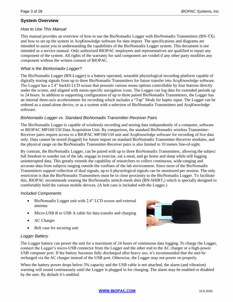
Included Components
• BioNomadix Logger unit with 2.4” LCD screen and external
antenna
• Micro-USB B to USB A cable for data transfer and charging
• AC Charger
• Belt case for securing unit
Logger Battery
The Logger battery can power the unit for a maximum of 24 hours of continuous data logging. To charge the Logger, connect the Logger’s micro-USB connector from the Logger and the other end to the AC charger or a high-power
USB computer port. If the battery becomes fully discharged after heavy use, it’s recommended that the unit be
recharged via the AC charger instead of the USB port. Otherwise, the Logger may not power on properly.
When the battery power drops below 5% capacity and the USB cable is not attached, the alarm (and vibration)
warning will sound continuously until the Logger is plugged in for charging. The alarm may be enabled or disabled
by the user. By default it’s enabled.

BioNomadix Logger™ User Guide Page 4 of 28
WWW.BIOPAC.COM 10.8.2020
The Logger battery is integrated internally and is not user replaceable. For battery replacement, contact BIOPAC.
To store the Logger for long periods of time, fully charge the battery using the AC charger and power off the Logger
to improve long-term battery performance.
Logger Interface and Button Controls
The various Logger options, such as pairing with BioNomadix Transmitters, starting/stopping recordings, setting audible alarms, adding markers, recording voice memos are controlled via selectable onscreen menus and accessed
via the four control buttons on the face of the unit. The screen icons and functions assigned to the physical buttons
will vary slightly depending on which Logger menu is active. The Logger LCD screen is not a touchscreen, but the four-button interface is very simple and the menus designed to be intuitive and easily navigable. The Main Screen
navigation button icons consist of (in order) Home, up-navigation, down-navigation, and “select.” (checkmark)
Button Icons
Home Button – aligns with left button in Main Screen only. Holding down for two seconds brings up an Options menu for setting the display to maximum brightness, restoring factory defaults or powering off.
Back button. Navigates back to previous menu screen. Aligns with first (left) button in all screens except the Main Screen.
Navigation arrow for moving up the selected menu screen. Aligns with second button.
Navigation arrow for moving down the selected menu screen. Aligns with third button.
Navigation arrow for moving left for horizontal selections. Aligns with second button in Date & Time screens.
Navigation arrow for moving right for horizontal selections. Aligns with third button in Date & Time screens.
Advances number selections, such as those found in the Date & Time screens. Aligns with fourth button.
Selection button for toggling through available options. Found in the Data Setup, Configuration and paired transmitter menus. Aligns with fourth button.
Select button. Accepts selected menu item or advances to next screen menu. Aligns with fourth button.
NOTE: During live data acquisition, the button icon status changes to allow for addition of event markers and
recorded audio notes into the session. See “Placing Event Markers” and “Audio Notes” see page 15 for details.
Charging and Powering on the Logger
Charge the Logger by connecting the micro USB B connector end of the charging cable to the Logger output port (on
top edge of unit) and connect the USB A end to the AC wall charger (included). Then power on the Logger by
holding down the leftmost button on the Logger’s front panel for a few seconds. The Logger welcome screen will
appear, followed by the Main Menu. Use the AC wall charger to charge the Logger, not a USB port.
When fully charged, the green battery icon in the upper right of the Main Menu screen will indicate “100%.”

Page 5 of 28 BIOPAC Systems, Inc.
WWW.BIOPAC.COM 10.8.2020
Sleep Mode and Automatic Power-Off
To conserve battery power, the Logger screen will automatically dim and go into a “sleep” mode if no button activity
is initiated for a period of 30 seconds. To wake the Logger, press any button and the most-recently used Logger screen will be displayed. If no Logger activity is registered for a default period of 30 minutes, the Logger will
automatically power off. If desired, the time interval defaults for sleep or power-off mode can be changed in the
Logger “Configure” settings. (See page 15.) While acquisitions are in progress the screen will dim, however the Logger will not power off until after the
acquisition is completed.
Resetting the Logger
The Logger can be reset by pressing the recessed Reset button located opposite the USB port. Use an unbent paper
clip to activate the button.
The Main Screen
The Main screen appears by default when the Logger is powered on, and provides access to the following menus:
• Data Setup – sets options for the internal accelerometer,
add/remove transmitters, tap mode options, recording duration and
transmitter frequency channels. (See subsequent table.)
• Configure – set the time and date, enable/disable Tap Interface, turn
on/off alarms, speaker/microphone, vibrate, adjust backlight,
display brightness, automatic power-off interval, User Alarms and
USB Wakeup.
• Acquire – manual or scheduled data recordings. (See page 12.)
• About – displays the following information: Number of logs,
available free memory, and firmware version.
Data Setup Options
Selecting the Main Screen > Data Setup menu screen displays the following setup menus.
Data Setup Menu Available Options
Description Available Settings
Summary --- Displays a screen showing the transmitter connection status along with other parameters, including type, acquisition sample rate, and duration. (See above right figure)
See page 6 for a full description of various Summary screen statuses and warnings.
Internal ACCL Check Data Provides visual feedback of accelerometer motion
---
Data Range Select accelerometer range 2g, 4g, 8g, 16g
Data Rate Select the accelerometer data acquisition sample rate
100 Hz, 200 Hz, 400 Hz
Tap Threshold The minimum amount of force required for Logger to respond to tap input.
1.0-6.0 g, in 0.5g increments

BioNomadix Logger™ User Guide Page 6 of 28
WWW.BIOPAC.COM 10.8.2020
Data Setup Menu Available Options
Description Available Settings
Tap Time The maximum amount of time a tap input must be above the Tap Threshold in order to qualify as a tap event.
1.25-15 ms, in 1.25 ms increments.
Tap Latency The wait time between the detection of a first tap event to the start of the time window during which a second tap event can be detected.
20-200 ms, in 20 ms increments
Tap Window The amount of time after the expiration of latency time during which a second valid tap can begin.
20-200 ms, in 20 ms increments
Add TX Device Screen shows “Scanning” and “Pair with this device?” prompts if supported BN-TX device is found.
Scans for an available BioNomadix Transmitter.
---
Duration Sets specified length for the data recording. 15 sec, 30 sec, 1 min, 5 min, 10 min, 30 min, 1 hr, 2 hrs, 5 hrs, 8 hrs, 12 hrs, 24 hrs
RF Channel Selects the radio channel used to exchange data between the transmitters and Logger. See page 14. If interference is encountered, select a different radio channel. If multiple Loggers are used in close proximity, for best results, each Logger should be set to a unique RF channel to avoid interference between the Loggers.
Increments of 3 ranging from 2-77.
Summary Screen Status and Warnings
The Data Setup > Summary screen displays a Status column indicating the readiness of the transmitter, and in certain
circumstances, may display a warning to the left of the Status column. The following statuses presented in the
Summary screen:
Status Color Description
“Ready” green Transmitter is on and has established good communication.
“Poor RF” amber Transmitter is on but communication between Logger and transmitter is poor and may be lost. Try adjusting transmitter positioning.
“Low Bat” amber Transmitter is on but has a low battery level and may not last for the entire acquisition. If possible, charge transmitter prior to acquisition.
“Lost” red Transmitter cannot be found. Transmitter may be powered off or is out of range of the Logger.
“Tst” red, to the left of the Status column
The transmitter is configured to record one of the test signals (e.g. sine wave, square wave) instead of a biopotential signal. Not necessarily an error if the user is using test signals to verify quality of a recording transmitter arrangement.
Page 7 of 28 BIOPAC Systems, Inc.
WWW.BIOPAC.COM 10.8.2020
If an error occurs, the following warnings are displayed in red text in the bottom half of the Summary screen:
Warning Description
“RF Failure!” Problem with the Logger radio. Try another Logger RF channel or contact BIOPAC Support.
“Low Battery!” Logger battery level is low and may not last for the entire acquisition. If possible, charge Logger prior to acquisition.
“No TX device()s!” No transmitters are paired with the Logger. May not be an error if logging using only the internal accelerometer.
“Low Memory” The Logger is running out of internal storage space. Delete some logs from the device to free up more space. (See page 21.)
“Low TX Battery(s)” At least one transmitter has a low battery. Check the Status column.
“Check/Turn TX(s) ON” At least one transmitter is not communicating with the Logger. Check the Status column.
“TX(s) in TEST Mode” At least one tranmitter is recording test signals. May not be an error if testing the transmitter configuration. Check the Status column.
When waking from sleep to perform a Preflight (see page 13): If any of the above warnings are present, the logger
will beep and/or vibrate continuously until a button is pressed to dismiss the warning.
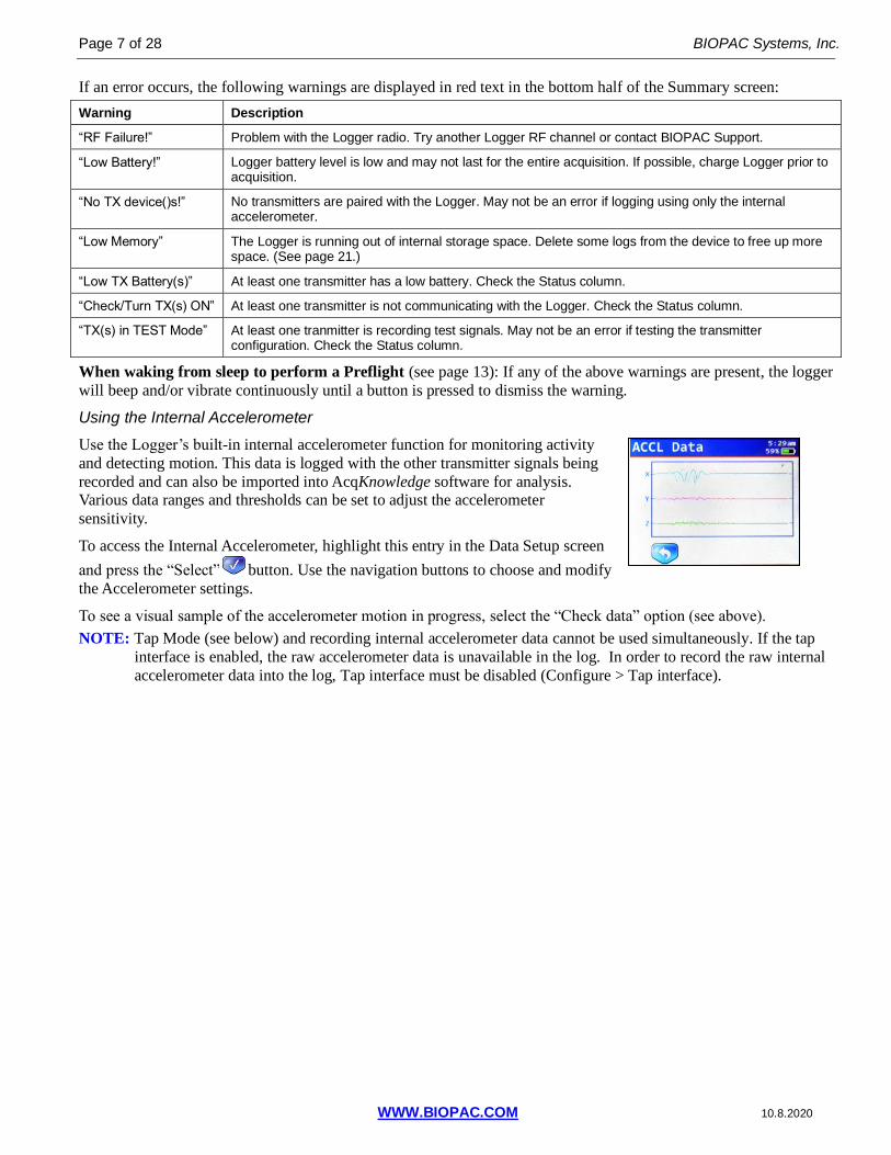
Using the Internal Accelerometer
Use the Logger’s built-in internal accelerometer function for monitoring activity
and detecting motion. This data is logged with the other transmitter signals being
recorded and can also be imported into AcqKnowledge software for analysis. Various data ranges and thresholds can be set to adjust the accelerometer
sensitivity.
To access the Internal Accelerometer, highlight this entry in the Data Setup screen
and press the “Select” button. Use the navigation buttons to choose and modify
the Accelerometer settings.
To see a visual sample of the accelerometer motion in progress, select the “Check data” option (see above).
NOTE: Tap Mode (see below) and recording internal accelerometer data cannot be used simultaneously. If the tap
interface is enabled, the raw accelerometer data is unavailable in the log. In order to record the raw internal
accelerometer data into the log, Tap interface must be disabled (Configure > Tap interface).
BioNomadix Logger™ User Guide Page 8 of 28
WWW.BIOPAC.COM 10.8.2020
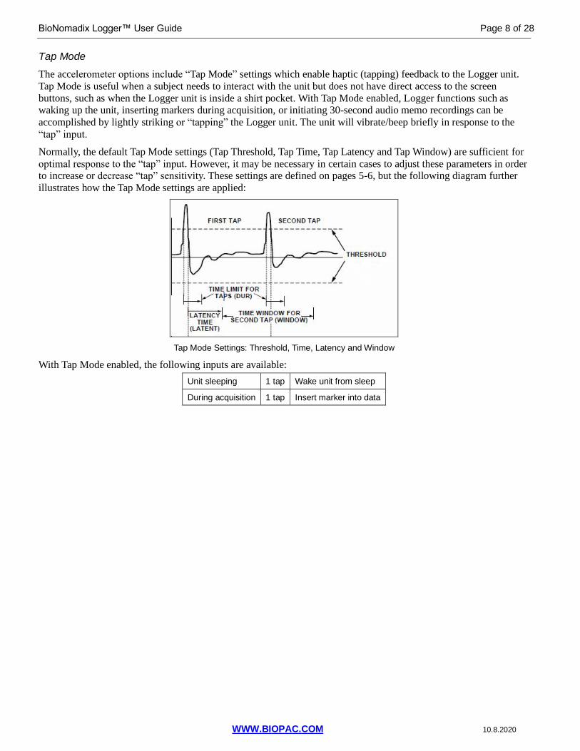
Tap Mode
The accelerometer options include “Tap Mode” settings which enable haptic (tapping) feedback to the Logger unit.
Tap Mode is useful when a subject needs to interact with the unit but does not have direct access to the screen
buttons, such as when the Logger unit is inside a shirt pocket. With Tap Mode enabled, Logger functions such as waking up the unit, inserting markers during acquisition, or initiating 30-second audio memo recordings can be
accomplished by lightly striking or “tapping” the Logger unit. The unit will vibrate/beep briefly in response to the
“tap” input.
Normally, the default Tap Mode settings (Tap Threshold, Tap Time, Tap Latency and Tap Window) are sufficient for
optimal response to the “tap” input. However, it may be necessary in certain cases to adjust these parameters in order to increase or decrease “tap” sensitivity. These settings are defined on pages 5-6, but the following diagram further
illustrates how the Tap Mode settings are applied:
Tap Mode Settings: Threshold, Time, Latency and Window
With Tap Mode enabled, the following inputs are available:
Unit sleeping 1 tap Wake unit from sleep
During acquisition 1 tap Insert marker into data

Page 9 of 28 BIOPAC Systems, Inc.
WWW.BIOPAC.COM 10.8.2020
Accelerometer Assisted Synchronization
The Logger can be precisely synchronized with the eye tracking scene camera via the following method.
1. Start the eye tracking and physiology recording.
2. Place the Logger in view of the scene camera and quickly tap the Logger three times.
The internal accelerometer will record the impact and you can later easily identify the onset of the impact in both the
physiology data and the video from the scene camera. The sample rate of the accelerometer is higher than the scene
camera frame rate and, therefore, data can be aligned within accuracy of a single video frame. This accelerometer-based approach is quite elegant, as it requires no cables or wireless connection methods to connect the Logger and
eye tracker, thus allowing the researcher to perform synchronization in a very simple and intuitive way.
Pairing the Logger with a BioNomadix Transmitter
The Logger will support pairing with up to three BioNomadix Transmitters. To pair with a transmitter, use the
following steps:
1. In the Logger Main Screen, select “Data Setup” and press the “Select” button.
2. Use the Logger “Data Setup” down-arrow button to scroll to “Add TX device” and press the
“Select” button. The Logger will begin scanning for transmitters to be paired.
3. Power on the BioNomadix Transmitter to be paired and use a pen or pencil to hold down the transmitter’s
“ID” button. The LED on the transmitter will turn solid orange. Continue holding down the ID button until
the Logger displays the “Pairing” screen for the transmitter.
4. The “Pairing” screen for the selected transmitter will be displayed, and the “ID” button may be released on
the transmitter. Press the “Select” (checkmark) button on the Logger to accept pairing with the selected
transmitter.
5. The newly-paired transmitter will appear as a new entry in the “Data Setup” menu. Pairing status and
transmitter battery power is indicated by a colored square to the right of the paired transmitter entry (above).
This square indicates the current battery level of the transmitter (green for full, yellow for half charge, red for
required charging or transmitter is off).
Note: The onscreen battery status light may cycle from red to yellow before becoming green depending on
the battery level of the transmitter.
6. To pair additional devices, use the down-arrow button in Data Setup to scroll to “Add TX device” and repeat
steps 1-4.
NOTE: Paired transmitters are retained in the Data Setup menu when powered off, but with a red square to
indicate the powered-off status. To recover the paired connection, simply turn the transmitter back on.
IMPORTANT: If the transmitters paired to a logger also have a receiver connected to the MP device, the receiver
must be powered off or out of range in order to record data using the data logger. When a transmitter is powered on or loses communication for two minutes it will begin or repeat its initial search sequence. The initial search sequence
first checks for any receiver. If no receiver is found, the transmitter will then search for a paired data logger.
To start logging data within the same lab as the receiver:
1. Quit the software and turn off your MP device to turn off power to the receiver.

BioNomadix Logger™ User Guide Page 10 of 28
WWW.BIOPAC.COM 10.8.2020
2. Turn the transmitter off and then back on (or wait two minutes).
3. Power on logger (if off). The transmitter will then be able to communicate with the logger.
Unpairing the Logger from a BioNomadix Transmitter
1. In the Logger Main Screen, select “Data Setup” and press the “Select” button.
2. In “Data Setup,” scroll down to the BN Transmitter entry to be unpaired and press the “Select” button.
3. Scroll down to the “Unpair TX” option in the BN Transmitter menu and press the “Select” button to
bring up the “Unpairing” screen.
4. Press the “Select” button in the “Unpairing” screen to remove the transmitter.
When a transmitter is unpaired, it is removed from the Data Setup menu.
Note: The transmitter does not need to be powered on or physically available for it to be unpaired.
Paired Transmitter Menus
Each paired transmitter will display as a unique entry in the Data Setup menu. With the transmitter selected in the
menu, access advanced options for the paired transmitter by clicking the “Select” button.
Transmitter Options
To access configurable options for the paired transmitter, highlight the transmitter entry in the Data Setup menu and
press the “Select” button. This opens a menu of available options for the selected transmitter, such as filtering,
acquisition rate, modes and sample test waves. These settings can be selected and adjusted via the Logger arrow and
selection buttons. For full BioNomadix Transmitter filter specs, see the BIOPAC BioNomadix Product Sheet or
BioNomadix User Guide.
The configurable settings are as follows. (BN-RSPEC is used as an example, other transmitter settings will vary)
Data Setup Function
Available Options
Description Available Settings
BN-RSPEC Transmitter
CH1 = RSP signal
CH2 = ECG signal
Check Data Show preview screen of selected test wave or data being acquired.
---
Reset Filters Resets the acquisition rate and filter settings back to the factory defaults
---
Acq Rate Shows acquisition sample rate 400 Hz*, 1000 Hz, 2000 Hz**
**If a BN-ACCL3 is paired, the 2000 Hz setting is not available.
*Lowest available sample rate may be 500 Hz, dependent upon sample rate settings of other paired transmitters.
Page 11 of 28 BIOPAC Systems, Inc.
WWW.BIOPAC.COM 10.8.2020
Data Setup Function
Available Options
Description Available Settings
Notch Filter Select notch filter setting Off, 60 Hz, 50 Hz
CH2 1 Hz HP Select CH2 high pass filter setting Off/On
CH2 35 Hz LP Select CH2 low pass filter setting Off/On
CH2 Mode Select CH2 ECG mode ECG/BPM
CH1 1 Hz LP Select CH1 low pass filter setting Off/On
CH1 0.5 Hz HP
Select CH1 high pass filter setting Off/On
Test Wave Select test wave type for display in the “Check Data” preview screen
Off/Zero/High/Low/Square/1 Hz SIN/4 Hz SIN/
Previewing Data
When acquisitions are running it is not possible to view raw data from the transmitters. Prior to starting a recording
on the Logger, it is recommended to preview the data to verify proper electrode connections and transducer
connections. Data may be previewed by using the “Check Data” option for each transmitter in the Data Setup menu.
This option will plot the data being recorded in real-time on the screen. Adjustments to electrodes or transducers will
be reflected in the signal on the screen.
The “Check Data” option may also be used to examine the transmitted data for any RF interference. RF interference
will be displayed as “spikes” in the data. While small amounts of RF interference should not be of much concern, if there is too much RF interference the Logger may not be able to record all of the transmitted data. The “Check Data”
screen may be used to visually examine the steps used to reduce RF interference such as: moving Logger closer to
the transmitter, changing the RF channel, and ensuring uninterrupted “line of sight” between Logger and transmitter.
Choosing an Acquisition Rate
Some transmitters may offer a selection of data acquisition rates in their transmitter options. Lower acquisition rates
may help improve radio communications between the transmitter and the Logger. Use the minimum rate needed to
record your data. Generally 2 kHz is recommended for EMG. For ECG, 1 kHz is the minimum recommended rate for
HRV studies; lower rates may be acceptable if just recording heart rate. 500 Hz should be sufficient for the majority
of other signal types.
Setting an Acquisition Length
Acquisition lengths ranging from 15 seconds to 24 hours are supported, and are started and stopped by selecting the
“Acquire” option in the Main Screen. To set the acquisition length:
In the Data Setup menu, scroll down to the “Duration” option and use the button to toggle through the available
durations. See the table on page 6 for complete acquisition duration options.

BioNomadix Logger™ User Guide Page 12 of 28
WWW.BIOPAC.COM 10.8.2020
Starting an Acquisition Manually
1. In the Main Menu, scroll to “Acquire” and press the “Select” button.
2. Make sure the Scheduler option is set to “Off.”
3. After setting the desired Duration (recording length), scroll up to the “Start” option and press the “Select”
button.
NOTE: The Duration can be set in the Data Setup or Acquire screens by selecting the “Duration” entry and
toggling to the desired duration using the button.
4. In the resulting “Summary” screen, press the “Select” button when prompted.
Once started, allow the acquisition to run for its selected duration until prompted that the recording is complete.
IMPORTANT: Do NOT connect the Logger to a computer while a data acquisition is in progress. The acquisition
will be halted and data will be lost if the Logger is connected to a computer while a data acquisition is in progress.
Starting an Acquisition at a Preset Time
An acquisition can be set to begin at a preset time by enabling the Acquire menu’s “Scheduler” option and setting the desired “Start Time.” To do this:
1. Scroll to the “Scheduler” option and use the button to toggle the selection to “On.”
2. Scroll to the “Start Time” option and press the “Select” button.
3. Use the navigation buttons and button to select the desired start time hour, minute, and am/pm
settings.
4. Use the button to scroll to “Set,” and press the “Select” button.
5. Scroll up to the “Start” option and press the “Select” button. A Summary screen will be
displayed, showing the time the acquisition will start. (See following page.)
6. Press “Start.” The Summary screen will display a countdown timer showing the time interval left
until start of acquisition. (See following page.)

Page 13 of 28 BIOPAC Systems, Inc.
WWW.BIOPAC.COM 10.8.2020
Preflight Setting
The Preflight setting automatically wakes the Logger unit from sleep prior to the start of a scheduled acquisition. (Preflight options are 2, 5, 8, or 15 minutes.) When enabled, the Preflight screen displays a countdown timer to the
acquisition start time, along with Summary information screen showing transmitter status. If an error is detected,
such as a transmitter not properly powered on, the Logger will vibrate/beep a warning. This gives the user sufficient
time to make a correction if necessary without aborting the acquisition. To set up a Preflight interval:
1. After setting a scheduled start time for an acquisition (Steps 1-4 above,) scroll to the “Preflight” option.
Use the button to select a Preflight interval. In the example above, a sleeping Logger will
automatically wake up five minutes prior to the scheduled start of acquisition.

BioNomadix Logger™ User Guide Page 14 of 28
WWW.BIOPAC.COM 10.8.2020
Checking for RF Interference during an Acquisition
The Logger does not support the display of raw signals during an acquisition. It is recommended that the “Check
Data” option be used prior to the start of an acquisition to verify proper electrode and transducer connections and
check for any excess RF interference. Additionally, prior to sending a subject for a long-term acquisition a short-term
acquisition should be performed to check data integrity.
During an acquisition, the progress bar indicates both the amount of data acquired as well as the RF signal integrity.
Green indicates successful communication between the Logger and all transmitters. A red bar indicates there were communication issues with at least one of the transmitters. Normally communication will be quickly re-established
between Loggers and transmitters. If the progress bar has prolonged periods of red indicating communication issues, one of the transmitters may have been turned off, run out of battery, or shifted position to be too far away from the
Logger. Even if a single transmitter is unable to communicate data will still be recorded from remaining transmitters.
Communication issues may still occur for a variety of reasons including external RF noise, multiple Loggers in close
proximity, and non-optimal physical setup.
Using Multiple Loggers in Close Proximity
Multiple Loggers may be used in close proximity to each other, such as recording multiple subjects within a single
room or using multiple Loggers to record data from more than three transmitters on a single subject.
Each Logger should be set to a unique RF channel to avoid RF interference between the Loggers.
If two Loggers are set to the same RF channel, communications loss will occur. The RF channel may be set in the Logger “Configure” menu. Use RF channels farther away from each other to minimize interference between
Loggers.
If a transmitter is paired to both a BioNomadix Logger and a BioNomadix Smart Center, note that only one of these units should be powered on at a time. To use the paired transmitters with a Logger, the Smart Center should be
disconnected from the computer. Conversely, to use the transmitters with the Smart Center, the Logger should be
turned off.
Optimizing Physical Configuration for Best Recordings
Unlike the standard BioNomadix receivers, the Logger is a battery operated low power radio device designed for
“body area networks” where the Loggers and transmitters are attached to a subject. Loggers should always be attached to the subject when possible to allow them to remain in close proximity to the transmitters. The maximum
recommended radio range between a Logger and an individual transmitter is approximately one meter. Even then,
minimizing the distance between the Logger and a transmitter will improve radio communications. When multiple transmitters are in use, it is recommended to place the Logger physically as close as possible to the transmitter
operating at the highest sampling rate (e.g. EMG, ECG signals). If all transmitters are operating at the same rate,
attempt to position the Logger equidistant between all transmitters.
Avoid “body blocking” whenever possible. “Body blocking” is when a straight line drawn from a transmitter to the
Logger would intersect the human body. The human body absorbs RF energy at known rates (SAR). If portions of
the body are between the transmitter and a Logger, the reduction in signal strength will affect communications. To achieve the best communications possible, keep an open “line of sight” between the Logger and transmitters that
does not intersect the body or intersects the least amount of body as possible. Keep the Logger and all transmitters on
the front (or back) of the body and, if possible, on the same side of the body. The optimal setup will depend on
transmitter placement and locations required for the various signal types.
Communications may also be affected by relative motion between the Logger and the transmitters. When possible,
keep the Logger and transmitter in close enough proximity to move roughly as a pair when the subject is in motion,
e.g. if transmitter is affixed to the torso, affix the Logger to the torso as well if possible.
The BioNomadix Shirt (BN-SHIRT) has many storage locations for transmitters and the Logger that can help
configure and maintain an optimal body area network on the upper torso.

Page 15 of 28 BIOPAC Systems, Inc.
WWW.BIOPAC.COM 10.8.2020
Placing Event Markers during an Acquisition
After starting a Logger acquisition, the button icons on the “Acquire” screen will change appearance to allow for the
insertion of event markers. Event markers are useful for noting a particular point of interest in the data which can be
examined in greater detail after the logged data is imported into AcqKnowledge. There are three basic event marker types that can be inserted during acquisition:
Button Icon Corresponding Button Event Type Event Icon in AcqKnowledge
Left Event Type 1
Second from left Event Type 2
Third from left Event Type 3
To insert an event at any time during acquisition, simply press the button corresponding to the desired event type.
Repeated presses will create additional events.
Manually Stopping an Acquisition
To manually abort (stop) an acquisition before it has completed its run, hold down the leftmost button. When the
button icon changes to an upward arrow , press the “Back” button.
To save the completed portion of the aborted acquisition, press the “Select” button.
To discard the acquisition, press the “Back” button to return to the Main Screen.
Adding an Audio Note
Add an audio note at any time during acquisition by holding down the rightmost “microphone” button. Speak
clearly in order for the built-in Logger microphone to pick up the audio. When finished speaking, release the button.
You may add as many audio notes as you wish during an acquisition.
Audio notes will be imported into AcqKnowledge along with the logged data and accompanying events.
Configure Menu
The Configure menu is the second entry in the Main Screen, and displays menus for setting the time and date, and for
adjusting the Logger settings.
Configure Function
Available Options
Description
Date & Time Date Set calendar date using the navigation buttons. Select “SET” to accept settings.
Time Set time using navigation buttons. Select “SET” to accept settings.
Time Format Set 12 or 24 hour time format using the rightmost button.
Time Zone Sets the time zone in terms of hours away from Greenwich Mean Time (GMT) using the navigation buttons. Select “SET” to accept settings.
BioNomadix Logger™ User Guide Page 16 of 28
WWW.BIOPAC.COM 10.8.2020
Configure Function
Available Options
Description
DST Indicates if Daylight Savings Time is being used. If the DST adjustment is set to Manual,
use the button to change DST to “ON” or “OFF.”
Adjust DST Choose between automatic Daylight Savings Time adjustment for USA and Europe (see below), or disable to adjust DST manually.
Date Format Changes the ordering used to display dates (month/day/year, day/month/year, year/month/day).
Low Bat. Alarm On/Off Turn On/Off low battery alarm.
Tap Interface On/Off Enables or disables Tap Mode options for the Internal Accelerometer (see page 6).
Speaker On/Off Turn On/Off speaker.
Vibration On/Off Turn vibration mode On/Off.
Microphone Sample Rate Sets microphone recording sample rate. Available rates are 8 KHz and 16 KHz.
Gain Sets the microphone gain input level. Available gain levels are 40 db or 50 db.
Attack Adjusts level of microphone adaptable gain pre-amplifier. Available levels are 1:500 and 1:2000.
Record Records an audio WAV file. The file is stored on the Logger device and is not directly importable into AcqKnowledge software. (It can be copied to the computer manually.)
Backlight Brightness Adjust brightness/dimness of display: “-“or “+”
Display Off Sets time interval before screen display dims. Available intervals are 30 sec, 1 min, 2 min, 4 min, 8 min
Power Off Sets time interval before power turns off automatically. Available intervals are 1 min, 5 min, 15 min, 30 min. A lower number will increase battery life.
Lock Screen On/Off The Lock Screen prevents access to any of the Logger buttons during an active acquisition. The lock can be set to engage after, 2, 5, 10, or 20 seconds after the start of acquisition. See page 19 for details about defeating the lock screen during a recording.
User Alarms On/Off Enables support for Logger User Alarms, which are used to remind subjects to perform certain activities at set times during an acquisition. User Alarms are configured in the AcqKnowledge software. For details on setting up User Alarms, see page 23.
USB Wakeup On/Off When "On" (default), the Logger will wake up automatically when a USB cable connected to a computer is plugged into a Logger. When "Off", the Logger will need to be manually powered on prior to connecting it to a computer.
NOTE: For certain computers, Loggers may be unable to go to sleep after being connected. If this occurs, the solution is to turn USB Wakeup to the "Off" setting.
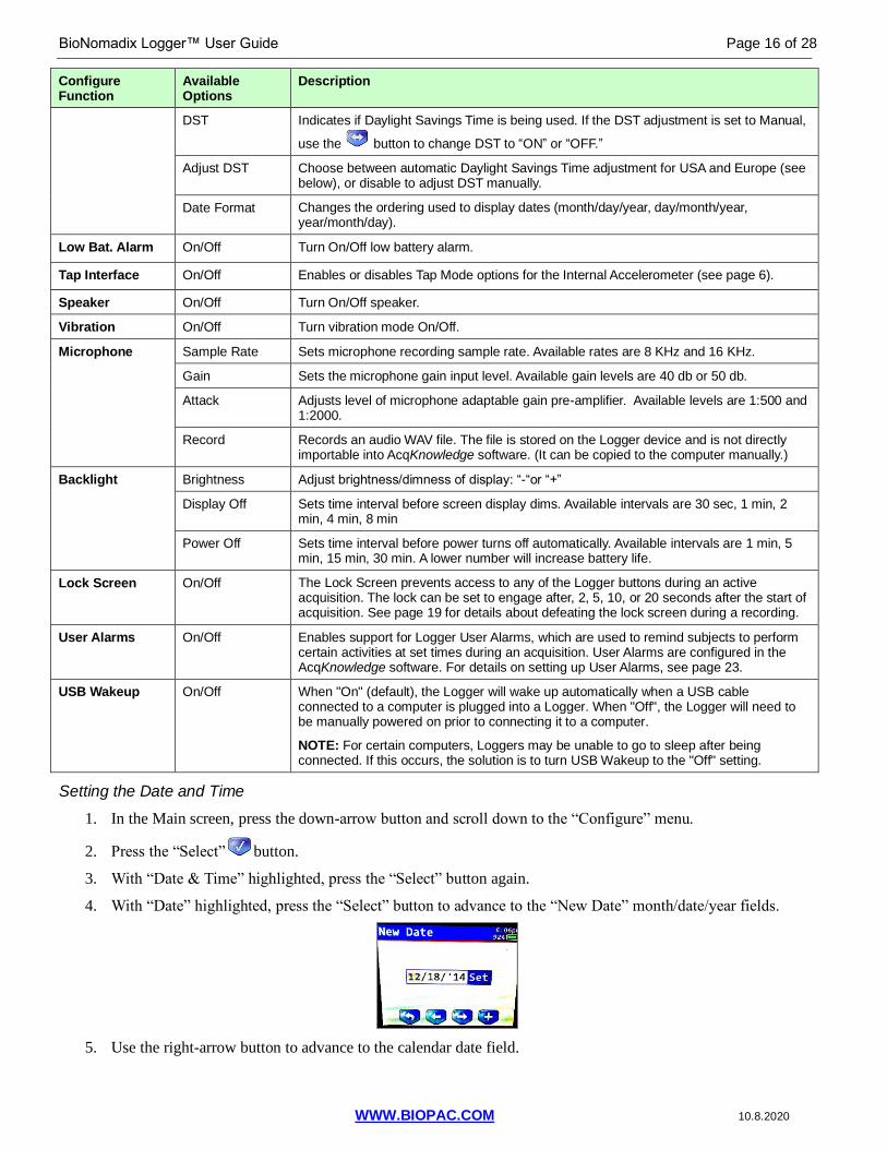
Setting the Date and Time
1. In the Main screen, press the down-arrow button and scroll down to the “Configure” menu.
2. Press the “Select” button.
3. With “Date & Time” highlighted, press the “Select” button again.
4. With “Date” highlighted, press the “Select” button to advance to the “New Date” month/date/year fields.
5. Use the right-arrow button to advance to the calendar date field.
Page 17 of 28 BIOPAC Systems, Inc.
WWW.BIOPAC.COM 10.8.2020
6. Use the “+” button to advance the numbers to the current date (both numbers may need to be advanced).
7. Use the right-arrow button to advance to the year field.
8. Use the “+” button to advance the numbers to the current year (both numbers may need to be advanced).
9. Use the right-arrow button to advance to highlight “Set” and press the “Select” button.
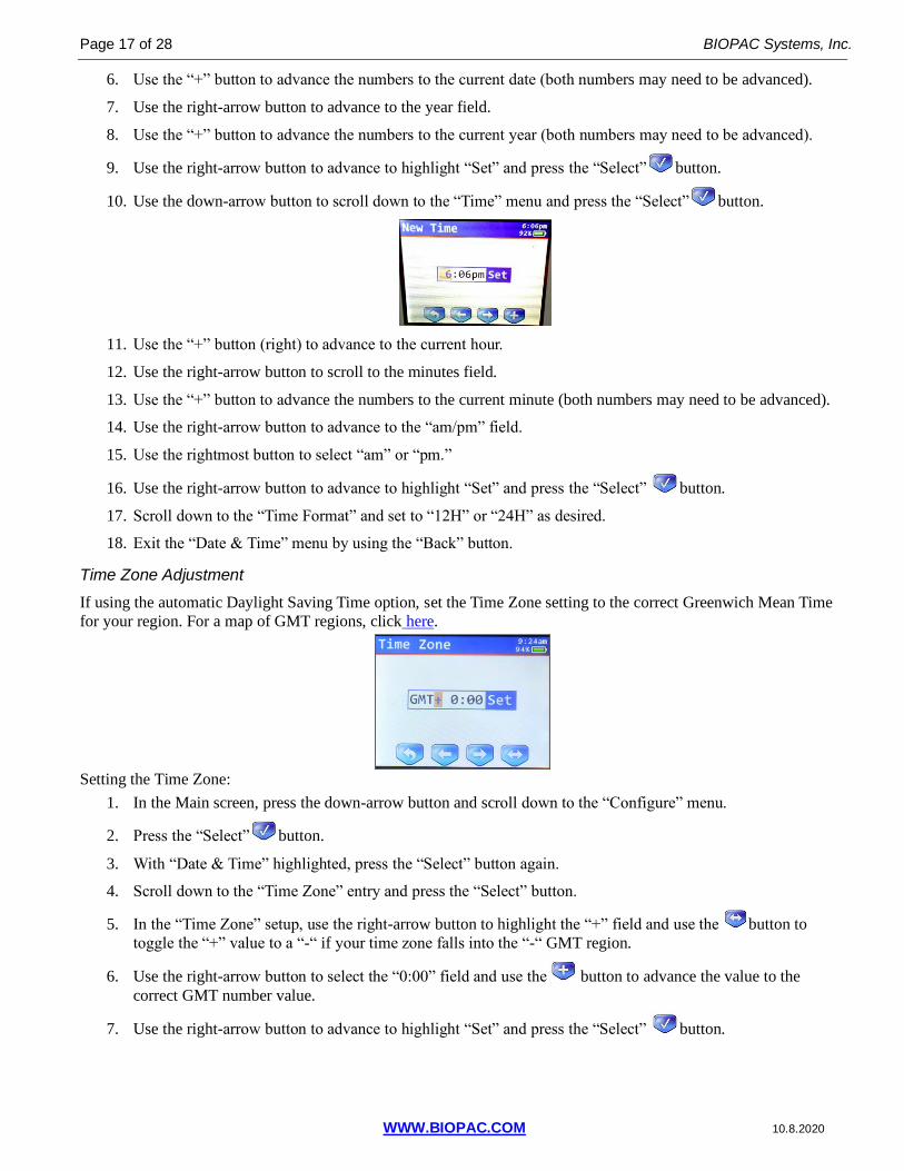
10. Use the down-arrow button to scroll down to the “Time” menu and press the “Select” button.
11. Use the “+” button (right) to advance to the current hour.
12. Use the right-arrow button to scroll to the minutes field.
13. Use the “+” button to advance the numbers to the current minute (both numbers may need to be advanced).
14. Use the right-arrow button to advance to the “am/pm” field.
15. Use the rightmost button to select “am” or “pm.”
16. Use the right-arrow button to advance to highlight “Set” and press the “Select” button.
17. Scroll down to the “Time Format” and set to “12H” or “24H” as desired.
18. Exit the “Date & Time” menu by using the “Back” button.
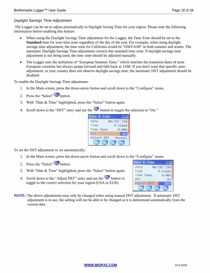
Time Zone Adjustment
If using the automatic Daylight Saving Time option, set the Time Zone setting to the correct Greenwich Mean Time
for your region. For a map of GMT regions, click here.
Setting the Time Zone:
1. In the Main screen, press the down-arrow button and scroll down to the “Configure” menu.
2. Press the “Select” button.
3. With “Date & Time” highlighted, press the “Select” button again.
4. Scroll down to the “Time Zone” entry and press the “Select” button.
5. In the “Time Zone” setup, use the right-arrow button to highlight the “+” field and use the button to
toggle the “+” value to a “-“ if your time zone falls into the “-“ GMT region.
6. Use the right-arrow button to select the “0:00” field and use the button to advance the value to the
correct GMT number value.
7. Use the right-arrow button to advance to highlight “Set” and press the “Select” button.
BioNomadix Logger™ User Guide Page 18 of 28
WWW.BIOPAC.COM 10.8.2020
Daylight Savings Time Adjustment
The Logger can be set to adjust automatically to Daylight Saving Time for your region. Please note the following
information before enabling this feature:
• When using the Daylight Savings Time adjustment for the Logger, the Time Zone should be set to the
Standard time for your time zone regardless of the day of the year. For example, when using daylight
savings time adjustment, the time zone for California would be “GMT-8:00” in both summer and winter. The
automatic Daylight Savings Time adjustment corrects this standard time zone. If daylight savings time
adjustment is not being used, the time zone should be adjusted manually.
• The Logger uses the definition of “European Summer Time,” which matches the transition dates of most
European countries but always jumps forward and falls back at 1AM. If you don't want that specific auto-
adjustment, or your country does not observe daylight savings time, the automatic DST adjustment should be
disabled.
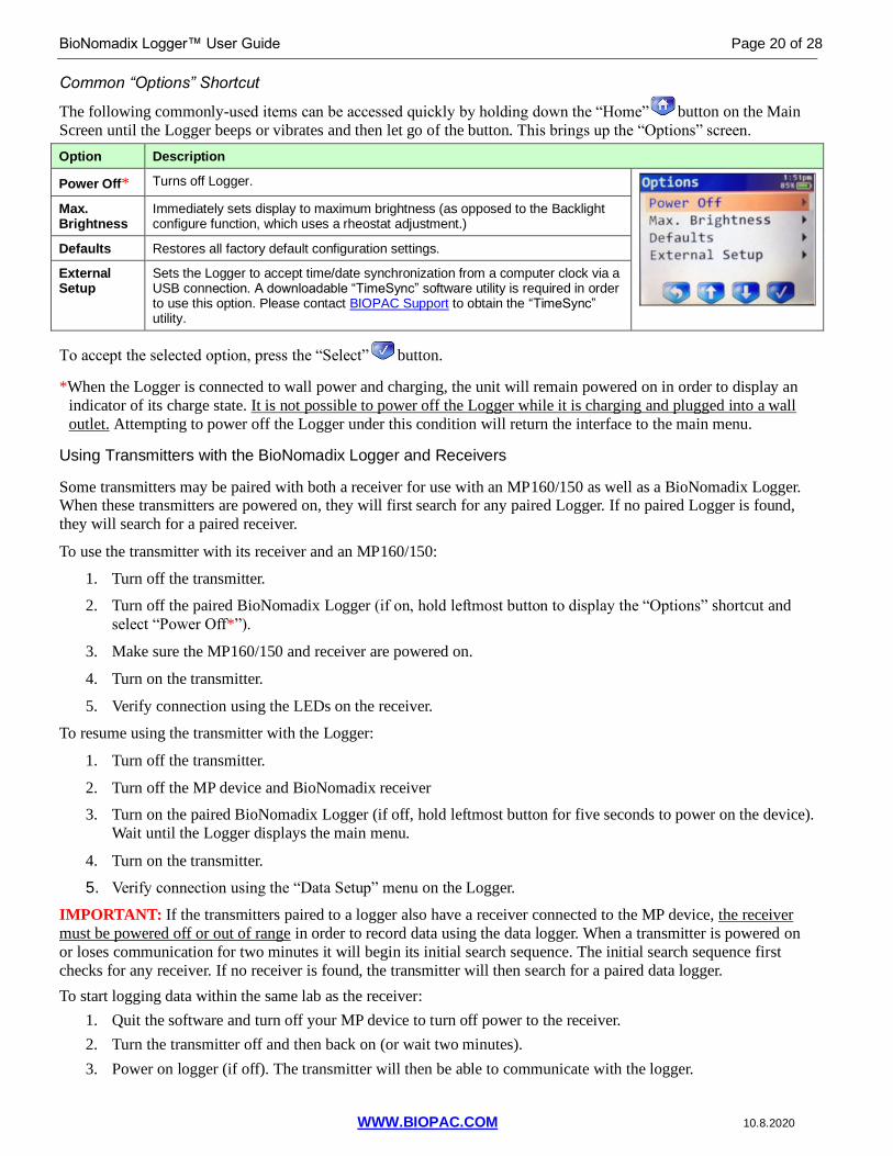
To enable the Daylight Savings Time adjustment:
1. In the Main screen, press the down-arrow button and scroll down to the “Configure” menu.
2. Press the “Select” button.
3. With “Date & Time” highlighted, press the “Select” button again.
4. Scroll down to the “DST” entry and use the button to toggle the selection to “On.”
To set the DST adjustment to set automatically:
1. In the Main screen, press the down-arrow button and scroll down to the “Configure” menu.
2. Press the “Select” button.
3. With “Date & Time” highlighted, press the “Select” button again.
4. Scroll down to the “Adjust DST” entry and use the button to
toggle to the correct selection for your region (USA or EUR).
NOTE: The above adjustments may only be changed when using manual DST adjustment. If automatic DST
adjustment is in use, the setting will not be able to be changed as it is determined automatically from the
current date.

Page 19 of 28 BIOPAC Systems, Inc.
WWW.BIOPAC.COM 10.8.2020
Configuring the Microphone
Use the following steps to configure the Microphone settings used for recording
Audio Notes during acquisition. (The default Microphone settings are normally
adequate for most purposes.)
1. In the Main screen, press the down-arrow button and scroll down to the
“Configure” menu.
2. Press the “Select” button.
3. Scroll down to “Microphone” and press the “Select” button to access the Microphone options.
4. Set the sample rate, gain and attack settings. (Recommended: Sample Rate: 8 KHz, Gain 50 dB, Attack
1:2000).
5. To record a test WAV file, choose “Record.” The audio waveform being recorded will be displayed in a
sample screen.
6. To stop and save the sample recording, press the “Select” button. To discard the sample recording,
choose the “Back” button.
NOTE: Sample recordings are not playable on the Logger, but are saved on the Logger in a folder called “Waves.” These files can be copied from the Logger to your computer and played back via Windows Media Player or
other supported audio application.
Lock Screen
The Lock Screen option is used for preventing unauthorized access or accidental triggering of the button display
during acquisition. When this is engaged, a “Screen Locked” message will appear on the Logger acquisition screen.
If it becomes necessary to defeat the screen lock during the recording, use the following steps:
1. Hold down the leftmost marker button until the “Press MIC key to unlock” message appears.
2. Release the button and quickly press the (microphone) key.
The above combination must be performed quickly in series. If the screen does not unlock, the MIC key was
probably not pressed rapidly enough in response to the prompt. Try the above steps again more quickly.
Setting other Configuration Options
See the table on page 15 for additional configuration options, such as setting the battery alarm, speaker, vibration mode, backlight, display brightness, automatic power-off interval, User Alarms and USB Wakeup.
Return to Main Screen Shortcut
To quickly return to the Main Screen from any menu, hold down the left button for two seconds or until the
Logger beeps or vibrates, and let go of the button.
BioNomadix Logger™ User Guide Page 20 of 28
WWW.BIOPAC.COM 10.8.2020
Common “Options” Shortcut
The following commonly-used items can be accessed quickly by holding down the “Home” button on the Main
Screen until the Logger beeps or vibrates and then let go of the button. This brings up the “Options” screen.
Option Description
Power Off* Turns off Logger.
Max. Brightness
Immediately sets display to maximum brightness (as opposed to the Backlight configure function, which uses a rheostat adjustment.)
Defaults Restores all factory default configuration settings.
External Setup
Sets the Logger to accept time/date synchronization from a computer clock via a USB connection. A downloadable “TimeSync” software utility is required in order to use this option. Please contact BIOPAC Support to obtain the “TimeSync” utility.
To accept the selected option, press the “Select” button.
*When the Logger is connected to wall power and charging, the unit will remain powered on in order to display an
indicator of its charge state. It is not possible to power off the Logger while it is charging and plugged into a wall
outlet. Attempting to power off the Logger under this condition will return the interface to the main menu.
Using Transmitters with the BioNomadix Logger and Receivers
Some transmitters may be paired with both a receiver for use with an MP160/150 as well as a BioNomadix Logger. When these transmitters are powered on, they will first search for any paired Logger. If no paired Logger is found,
they will search for a paired receiver.
To use the transmitter with its receiver and an MP160/150:
1. Turn off the transmitter.
2. Turn off the paired BioNomadix Logger (if on, hold leftmost button to display the “Options” shortcut and
select “Power Off*”).
3. Make sure the MP160/150 and receiver are powered on.
4. Turn on the transmitter.
5. Verify connection using the LEDs on the receiver.
To resume using the transmitter with the Logger:
1. Turn off the transmitter.
2. Turn off the MP device and BioNomadix receiver
3. Turn on the paired BioNomadix Logger (if off, hold leftmost button for five seconds to power on the device).
Wait until the Logger displays the main menu.
4. Turn on the transmitter.
5. Verify connection using the “Data Setup” menu on the Logger.
IMPORTANT: If the transmitters paired to a logger also have a receiver connected to the MP device, the receiver
must be powered off or out of range in order to record data using the data logger. When a transmitter is powered on
or loses communication for two minutes it will begin its initial search sequence. The initial search sequence first
checks for any receiver. If no receiver is found, the transmitter will then search for a paired data logger.
To start logging data within the same lab as the receiver:
1. Quit the software and turn off your MP device to turn off power to the receiver.
2. Turn the transmitter off and then back on (or wait two minutes).
3. Power on logger (if off). The transmitter will then be able to communicate with the logger.

Page 21 of 28 BIOPAC Systems, Inc.
WWW.BIOPAC.COM 10.8.2020
Importing Logged Data into AcqKnowledge
Data stored on the Logger can easily be imported into AcqKnowledge software for analysis. There are several
methods for importing logged data.
Method 1:
1. Connect the Logger to a computer USB port using the provided cable. The Logger will appear as an
additional disk drive on your computer.
2. Launch AcqKnowledge and select “BioNomadix Logger” in the Startup Wizard.
3. Select “Import Logs” and click OK to bring up the AcqKnowledge “Log Import” window.
Select the desired session(s) in the “Import” checklist and click the “Import” button. To select or deselect all
of the entries at the same time, hold down the Alt/Option key while clicking any of the “Import” checkboxes
4. Select the data channels to be imported into the new AcqKnowledge graph and click “Import” (above right).
TIP: You also have the option to selectively delete unwanted sessions before importing the ones you want to
keep (Delete Now), or automatically delete all sessions from the Logger after importing. (See checkbox)
5. After clicking OK, the imported data and selected channels will be displayed in an AcqKnowledge graph for
viewing and analysis along with a confirmation dialog.

BioNomadix Logger™ User Guide Page 22 of 28
WWW.BIOPAC.COM 10.8.2020
Method 2:
1. With an AcqKnowledge window running, connect the Logger to a USB port. When the Logger is recognized, the Logger import palette will appear (see below). By default, the import palette remains in view in the
AcqKnowledge interface the entire time a Logger is connected. It can be dragged and repositioned as desired.
2. Choose “Import Logs” and follow Steps 4 and 5 from the previous page.
Quick Import Latest Log – Use this option as a shortcut for importing the most recently-acquired log only. When
choosing this option, the Log Import window is bypassed and data for the most recent session is imported
immediately. No other logs are imported when using this option.
Import Logs – This option brings up the “Log Import” window described in Step 4 of the previous page.
Set Alarms – This option launches the User Alarm configuration window. (See page 23).
Disconnect – This option removes the Logger connection from the computer.
AcqKnowledge Menu Logger Options
Several Logger-related options become active in the AcqKnowledge MP menu when the Logger is connected.
Search for BioNomadix Loggers – Manually searches for attached Logger devices. If a mounted Logger is found,
the Logger palette will be displayed. This menu option is only applicable when the “Auto-connect to BioNomadix
Loggers” option is unchecked in the AcqKnowledge Hardware preferences. (Display > Preferences > Hardware)
Quick Import BioNomadix Log – An alternate method of accessing the “Quick Import Latest Log” feature
described above.
Import BioNomadix Logs – An alternate method of accessing the “Import Logs” feature described above.
Import BioNomadix Logs from Disk – This option enables the import of Logger data stored in locations other than
the Logger to be imported into AcqKnowledge. See following page for full description.
Configure BioNomadix Logger Alarms – This option is used to set up an alarm cue to appear on the Logger screen
at a preset time during an acquisition. See page 23 for a description of User Alarms.
Disconnect BioNomadix Logger – Removes the Logger connection from the computer.

Page 23 of 28 BIOPAC Systems, Inc.
WWW.BIOPAC.COM 10.8.2020
Import Logs from Disk Option
Each Logger data session resides in a LOG folder containing the unique files required for accurate data import into
AcqKnowledge. Since the Logger is accessible as a mounted drive on the computer when connected, these LOG folders can be copied to an alternate location and imported into AcqKnowledge from that location at a later time if
desired. The “Import Logs from Disk” option is used for browsing and selecting the log for import.
To use this option:
1. Select the “Import Logs from Disk” in the Startup Wizard or in the MP (hardware) menu in AcqKnowledge.
This will open the “which directory contains the BioNomadix Log data?” dialog.
OR
2. Browse to the location of the LOG folder highlight it, and click “Choose.”
3. Select the channels for import and click “Import.”
BioNomadix Logger User Alarms
User Alarms can be used to cue a subject to begin a particular activity at a particular time during an acquisition. Once
set, the alarm appears as fixed text on the Logger acquisition screen. An audible alarm pulse/vibration can be set up
as a cue to the user to perform the required activity shown on the Logger acquisition screen. Multiple user alarms for
multiple or repeated activities can be set up quickly, and accessed via the initial Logger import palette, or the
“Configure BioNomadix Logger Alarms” MP menu item.
Available Options:
Time – Use to set the time the User Alarm reminder will appear in the Logger acquisition screen. The text in the
Time field is editable, or use the arrow buttons to modify the selected values. The alarm time must coincide with an
active Logger acquisition. (For example, an acquisition must be taking place during the time the alarm becomes
active or no alarm will be triggered.)
Label – This is an editable field to create the reminder text that will appear on the Logger acquisition screen at the
time the alarm is set for. There is a 16 character limit on the reminder text.
Count – Use to set the number of audible or vibration alerts that occur when the alarm takes effect. This acts as an
physical reminder to the user to begin the required activity. Up to 10 beeps or vibration pulses are supported.

BioNomadix Logger™ User Guide Page 24 of 28
WWW.BIOPAC.COM 10.8.2020
New Alarm – Use this button to create a new alarm in the list. Newly added alarms are independent of previous or
existing alarms, and multiple alarms can be added.
Delete – Deletes a selected alarm from the list.
Delete All – Clears all alarms from the list.
Setting Up a User Alarm
1. Access the BioNomadix Alarms dialog by choosing “Set Alarms” in the BioNomadix Logger import palette
(this appears immediately after connecting the Logger to the computer), or in AcqKnowledge via the MP
menu item “Configure BioNomadix User Alarms.”
2. Edit the “Time” field to reflect the desired clock time for the User Alarm to activate.
3. Enter the desired user Alarm prompt text into the “Label” field. (This text will appear in the Logger
acquisition screen at the set time the alarm activates.)
4. Use the arrow buttons in the “Count” field to set the number of audio or vibration alerts emitted by the
Logger at the set time the User Alarm becomes active.
5. If desired, use the “New Alarm” button to create additional alarms to trigger at later times during the Logger
acquisition.
6. Click OK.
Remember: The User Alarm time must fall within a time a Logger acquisition is taking place in order for the alarm
to take effect.
Reviewing Imported Logger Events and Audio Notes
Events and audio notes inserted during a Logger acquisition can be reviewed and
modified in AcqKnowledge by using the Event palette.
1. With the imported Logger data open in AcqKnowledge, choose the
Event palette via the toolbar icon .
(If the Event palette toolbar icon is not visible, you can also enable
the palette via Display > Show > Event Bar and Events.)
2. Select an event of interest in the Events list to highlight it in the
graph.
3. Use the “Audio” option at the bottom of the Events palette to play
audio notes recorded during the Logger acquisition (see page 15).
Associated audio can be removed and re-recorded from within the
Events palette if desired. (Clicking “Remove” removes the audio only, not the Audio Note event.)
For more information on adding and creating Events, see the AcqKnowledge
Software Guide or watch the online Events Tutorial Video.
Page 25 of 28 BIOPAC Systems, Inc.
WWW.BIOPAC.COM 10.8.2020
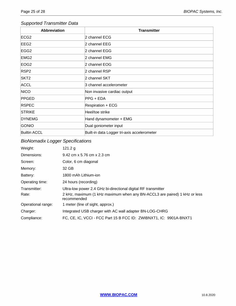
Supported Transmitter Data
Abbreviation Transmitter
ECG2 2 channel ECG
EEG2 2 channel EEG
EGG2 2 channel EGG
EMG2 2 channel EMG
EOG2 2 channel EOG
RSP2 2 channel RSP
SKT2 2 channel SKT
ACCL 3 channel accelerometer
NICO Non invasive cardiac output
PPGED PPG + EDA
RSPEC Respiration + ECG
STRIKE Heel/toe strike
DYNEMG Hand dynamometer + EMG
GONIO Dual goniometer input
Builtin ACCL Built-in data Logger tri-axis accelerometer
BioNomadix Logger Specifications
Weight: 121.2 g
Dimensions: 9.42 cm x 5.76 cm x 2.3 cm
Screen: Color, 6 cm diagonal
Memory: 32 GB
Battery: 1800 mAh Lithium-ion
Operating time: 24 hours (recording)
Transmitter: Ultra-low power 2.4 GHz bi-directional digital RF transmitter
Rate: 2 kHz, maximum (1 kHz maximum when any BN-ACCL3 are paired) 1 kHz or less recommended
Operational range: 1 meter (line of sight, approx.)
Charger: Integrated USB charger with AC wall adapter BN-LOG-CHRG
Compliance: FC, CE, IC, VCCI - FCC Part 15 B FCC ID: ZWIBNXT1, IC: 9901A-BNXT1

BioNomadix Logger™ User Guide Page 26 of 28
WWW.BIOPAC.COM 10.8.2020
Logger Troubleshooting
Q: The BioNomadix Logger is not turning on (display is dark, no sound).
A: Make sure to press and hold the leftmost button for five seconds to power the unit on. If the unit does not power
on, the battery may be drained. Connect the unit to the included AC adapter and try again. Leave the unit
connected to the AC adapter until the battery is charged to 100%. Note that the clock will need to be reset.
Q: When the Logger is turned on, a red warning is displayed before reaching the main menu.
A: On power-on, the Logger performs an internal hardware test. If one of these tests fails, a red warning will be
displayed. Pressing any button will dismiss this warning. Contact BIOPAC technical support for assistance. The
Logger may continue to function although its functionality will be impaired.
Q: The Logger keeps displaying the “BioNomadix” screen every 5 seconds.
A: The Logger is experiencing a fault that is causing the self-test to be run repeatedly. Contact BIOPAC technical
support.
Q: Pressing the button on the screen does not seem to be working.
A: The Logger does not use a touchscreen. Press the button area underneath the screen to activate the soft-button.
Q: I cannot pair the transmitter and the Logger.
A: Make sure to hold down the “ID” button on the transmitter until the transmitter light turns solid orange and the
Logger displays the pairing screen. If the pairing screen does not appear, the transmitter firmware may be out of
date. Firmware 4.0 or higher is required to use a transmitter with the BioNomadix Logger. This is shown on the
serial label of the transmitter. Older transmitters must be returned to BIOPAC for updates before they can be
used with the Logger. Contact BIOPAC technical support for assistance.
Q: During acquisitions I get a red progress bar and at completion I get a “data lost” message.
A: A transmitter may be off or there may be RF interference interrupting communications between the Logger and
transmitter. Make sure all transmitters are charged and powered on. Follow the guidelines for optimizing Logger
and transmitter configurations. Try using a different radio channel.
Q: The screen is too dim and the on-screen menus are not readable.
A: Press and hold the leftmost button to access the “Options” screen and choose “Max Brightness” to reset the
backlight level to 100%.
Q: The USB cable does not fit into the Logger.
A: The USB cable may be upside down. Flip the USB cable so the icon on the cable faces away from the screen and try to reconnect. Make sure you are using the USB cable supplied by BIOPAC with the Logger (Micro USB B).
Do not force the USB cable into the Logger!
Q: AcqKnowledge does not find the Logger and/or the “USB” screen on the Logger does not appear when
connecting the Logger to the computer. Logger indicates it is charging.
A: Unplug and replug the USB cable between the Logger and the computer.
Q: When the Logger is connected a “The disk you inserted is not readable by this computer” (OS X) or “USB
Device not recognized. You need to format this disk before you use it.” (Windows) error occurs.
A: The Logger must be connected directly to a primary USB port on the computer. Check that the USB cable is
plugged directly into the computer. The Logger may not be compatible with some front panel USB ports.
Q: The Logger is connected but when AcqKnowledge is launched the Logger unmounts or the disk unexpectedly
disappears.
A: The Logger must be connected directly to a primary USB port on the computer. Check that the USB cable is
plugged directly into the computer. The Logger may not be compatible with some front panel USB ports.

Page 27 of 28 BIOPAC Systems, Inc.
WWW.BIOPAC.COM 10.8.2020
If the computer only has USB 3, try connecting a powered USB 2.0 hub directly to the computer and then plug the
Logger into the hub.
Q: When the Logger is disconnected from the computer, the computer displays a warning “The disk was not ejected
properly” (OS X) or “Disk surprised removed/Problem ejecting USB mass storage device.” (Windows)
A: Make sure to disconnect the unit properly using the “Disconnect” button from the Logger palette in
AcqKnowledge. If unavailable, make sure to eject the BNLOGGER disk in the Finder (OS X) or use the Safely
Remove Hardware notification area icon to eject the BNLOGGER disk (Windows).
Q: The Logger does not appear to be charging.
A: The Logger may be connected to a low-power USB port, requiring the battery to be used to power the Logger.
The Logger must be connected to a high-power USB port or the included AC adapter to charge. Connect the
Logger to the included AC wall charger. If a Logger has a fully dead battery, computer USB ports may not provide enough power to allow the unit to fully power on, or it may freeze during power-on self-test. Batteries do
not charge during self test. If the Logger does not turn on:
1. Plug the Logger into mains power using the included AC power adapter until the Main menu appears.
2. Once the Main menu appears and the BioNomadix startup screen disappears, the Logger will begin
charging. Depending on how low the battery level has fallen the Logger may beep and attempt to restart
several times before reaching the Main menu.
3. Leave the logger connected to mains power for at least four hours to recharge the battery.
Q: The Logger does not power on after connecting to AC power for charging.
A: This can happen if the Logger has not been used for a long period of time and the battery has become fully
depleted. In this case there may not be enough power for the Logger to self start. If this occurs:
1. Plug the Logger into mains power using the included AC power adapter.
2. Power on the Logger by pressing and holding the leftmost button until the main menu appears.
3. Verify that the battery icon in upper right of the screen is blinking. This indicates the battery is charging.
Q: Unable to navigate between menu items on the Logger menus.
A: Multiple buttons may be being pressed at the same time. Make sure to press firmly directly on the white button
area towards the edge of the Logger case.
Q: When importing all logs appear to have a date of “January 2000”.
A: The clock on the Logger is not properly set. Set the proper date and time from the “Configure” menu.
Q: My Logger is beeping continuously!
A: The “low battery alarm” may be enabled. Disable the alarm from the “Configure” menu or plug the Logger into
an AC adapter to charge. If the Logger continues beeping, contact BIOPAC technical support.
Q: After importing the signal drops to zero in portions of the data.
A: The Logger was unable to communicate with the transmitter during these periods. Try using a different RF
channel and following the position optimization guidelines to improve RF performance.
Q: I connected the Logger to a computer while data acquisition was in progress and now I can't import my logged
data.
A: IMPORTANT: Do NOT connect the Logger to a computer while a data acquisition is in progress. The
acquisition will be halted and data will be lost if the Logger is connected to a computer while a data acquisition is
in progress.
Q: How do I reset the Logger?
A: The Logger can be reset by pressing the recessed Reset button located opposite the USB port. Use an unbent
paper clip to activate the button.

BioNomadix Logger™ User Guide Page 28 of 28
WWW.BIOPAC.COM 10.8.2020
Intended Use
BIOPAC Systems, Inc., instruments, components, and accessories are designed for educational- and research-oriented life science applications and investigations. BIOPAC Systems, Inc. does not condone the use of its instruments for clinical medical applications. Instruments, components, and accessories provided by BIOPAC Systems, Inc., are not intended for the diagnosis, cure, mitigation, treatment, or prevention of disease.
Warranty
BIOPAC Systems, Inc. warrants to the original end purchaser that
▪ the BioNomadix Logger™ hardware shall be free from material defects in material and workmanship for a period of one (1) year from the original date of purchase (the "Hardware Warranty Period")
▪ the software shall be free from material defects or errors for a period of one (1) year from the original date of purchase (the “Software warranty period”).
If the product is determined to be materially defective during the Warranty Period, your sole remedy and BIOPAC’s sole and exclusive liability shall be limited to the repair or replacement of this product with a new or refurbished product at BIOPAC’s or its licensed distributor’s option. For purpose of this Limited Hardware Warranty and Liability, "refurbished" means a product that has been returned to its original specifications. Visit WWW.BIOPAC.COM for instructions on how to deliver the product to an authorized service facility.
This warranty shall not apply if this product a) is used with products that are not compatible with this product b) is modified, or tampered with c) is damaged by acts of God, misuse, abuse, negligence, accident, wear and tear, unreasonable use, or by
other causes unrelated to defective materials or workmanship d) has had the serial number altered, defaced or removed e) has, in the reasonable opinion of BIOPAC or its licensed distributors, been opened, altered, or defaced.
This warranty shall also be voidable by BIOPAC or its licensed distributors
If (1) BIOPAC reasonably believes that the BioNomadix Logger™ system has been used in a manner that would violate the terms and conditions of a separate end user license agreement for system software; or (2) the product is used with products not sold or licensed by BIOPAC. You assume all risks and liabilities associated with use of third party products.
This warranty is provided to you in lieu of all other express or implied warranties including warranties of merchantability and fitness for a particular purpose for the BioNomadix Logger™ system, which are disclaimed hereunder. However, if such warranties are required as a matter of law, then they are limited in duration to the warranty period.
Our sole and exclusive recourse in the event of any dissatisfaction with or damage arising from the use of the BioNomadix Logger™ system and BIOPAC's maximum liability shall be limited to repair or replacement of the BioNomadix Logger™ system. Except as expressly stated above, BIOPAC excludes all liability for any loss of data, loss of profit, or any other loss or damage suffered by you or any third party, whether such damages are direct, indirect, consequential, special, or incidental and however arising under any theory of law, as a result of using your BioNomadix Logger™ system. Some countries, states or provinces do not allow limitation on how long an implied warranty lasts and some countries, states and provinces do not allow the exclusion or limitations of consequential or incidental damages, so the limitations or exclusions may not apply to you.
This warranty gives you specific legal rights, and you may also have other rights which vary from country to country, state to state or province to province. This warranty is in all countries where BIOPAC has an office or a licensed distributor. The warranty offered by BIOPAC Systems, Inc. on your BioNomadix Logger™ hardware is the same whether or not you register your product.