
Bionic Arduino Introduction to Microcontrollers with Arduino Class 4 20 Nov 2007 - machineproject -...
50
Bionic Arduino Introduction to Microcontrollers with Arduino Class 4 20 Nov 2007 - machineproject - Tod E. Kurt
-
Upload
chester-nicholson -
Category
Documents
-
view
245 -
download
1
Transcript of Bionic Arduino Introduction to Microcontrollers with Arduino Class 4 20 Nov 2007 - machineproject -...

Bionic Arduino
Introduction to Microcontrollers with Arduino
Class 4
20 Nov 2007 - machineproject - Tod E. Kurt

What’s for Today•About PWM
•Controlling Servos
•About the I2C bus
•Using I2C on Arduino
•About Accelerometers
•Nintendo Wii Nunchuck as Input Device

blink blin
k
blink blin
k
compile
upload
sketch runs
TX/RX flashLoad “File/Sketchbook/Examples/Digital/Blink”
Recap: Blinky LEDMake sure things still work

Pulse Width Modulation
•More commonly called “PWM”
•Computers can’t output analog voltages
•Only digital voltages (0 volts or 5 volts)
•But you can fake it
• if you average a digital signal flipping between two voltages.
•For example...

PWMOutput voltage is averaged from on vs. off time
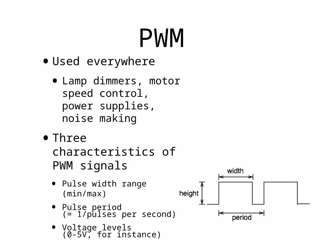
PWM•Used everywhere
• Lamp dimmers, motor speed control, power supplies, noise making
•Three characteristics of PWM signals
• Pulse width range (min/max)
• Pulse period(= 1/pulses per second)
• Voltage levels(0-5V, for instance)

Servomotors
•Can be positioned from 0-180º
• Internal feedback circuitry & gearing takes care of the hard stuff
•Easy three-wire PWM 5V interface
(usually)

Servos are Awesome
•DC motor
•High-torque gearing
•Potentiometer to read position
•Feedback circuitry to read pot and control motor
•All built in, you just feed it a PWM signal

Servos, good for what?
•Roboticists, movie effects people, and puppeteers use them extensively
•Any time you need controlled, repeatable motion
•Can turn rotation into linear movement with clever mechanical levers

Servos•Come in all sizes
•from super-tiny
•to drive-your-car
•But all have the same 3-wire interface
•Servos are spec’d by: 157g
9g
weight: 9g
speed: .12s/60deg @ 6V
torque: 22oz/1.5kg @ 6V
voltage: 4.6~6V
size: 21x11x28 mm
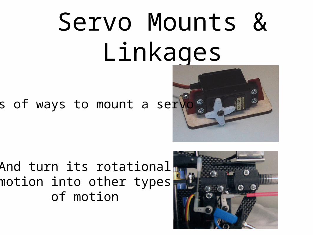
Servo Mounts & Linkages
Lots of ways to mount a servo
And turn its rotational motion into other types of
motion
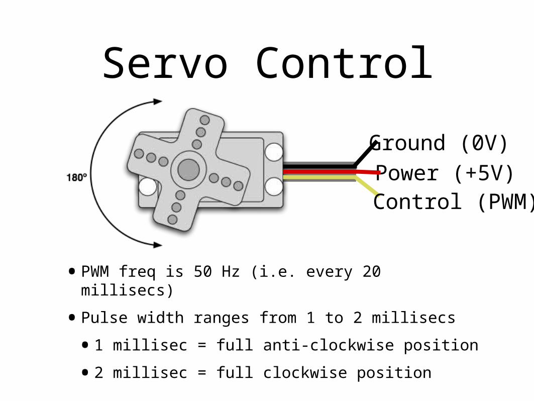
Servo Control
Power (+5V)Ground (0V)
Control (PWM)
•PWM freq is 50 Hz (i.e. every 20 millisecs)
•Pulse width ranges from 1 to 2 millisecs
•1 millisec = full anti-clockwise position
•2 millisec = full clockwise position
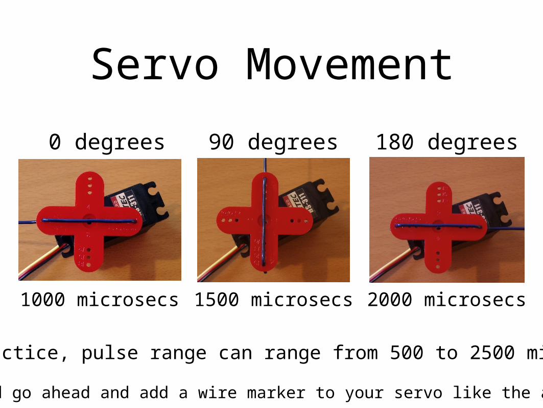
Servo Movement
0 degrees 90 degrees 180 degrees
1000 microsecs 1500 microsecs 2000 microsecs
In practice, pulse range can range from 500 to 2500 microsecs
(and go ahead and add a wire marker to your servo like the above)

Servo and ArduinoFirst, add some jumper wires to the servo
connector
Gnd
Power
PWM control
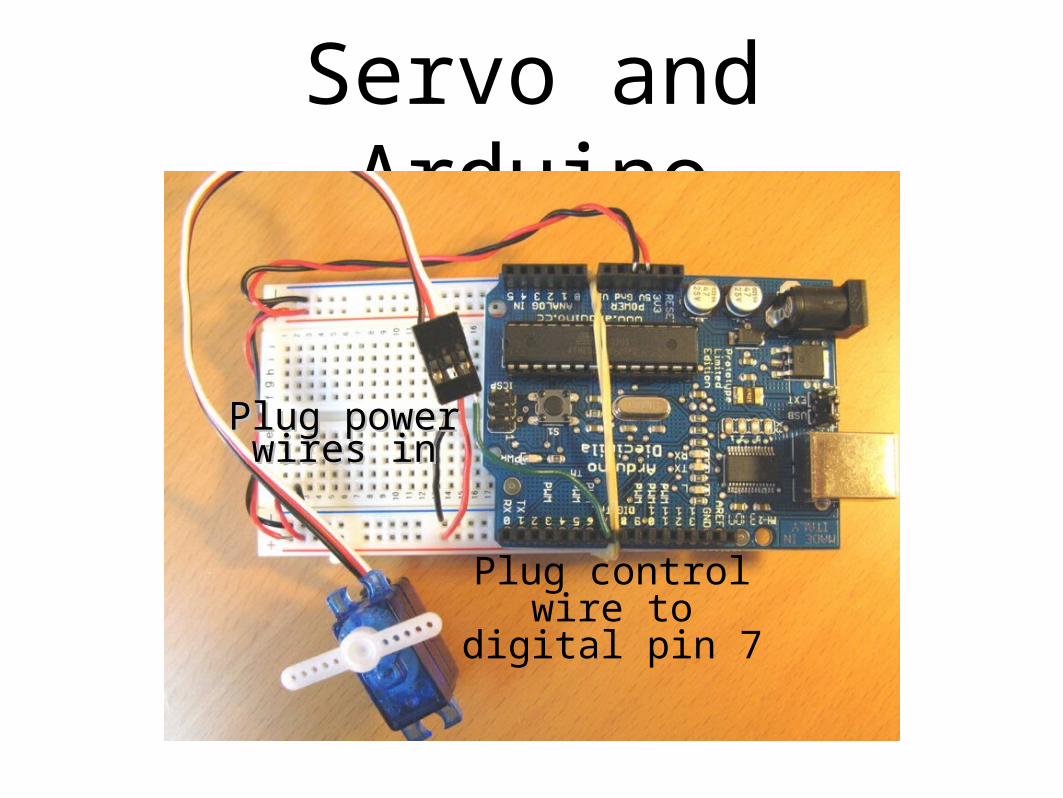
Servo and Arduino
Plug control wire to digital
pin 7
Plug powerPlug powerwires inwires in
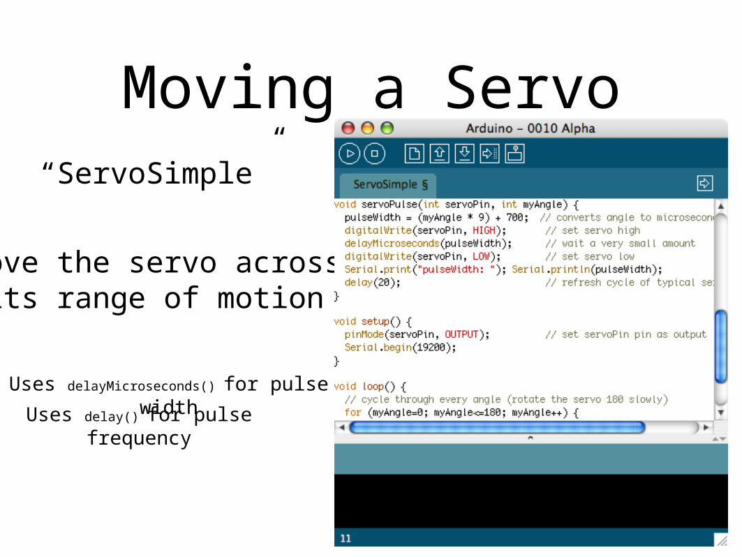
Moving a Servo
Move the servo acrossits range of motion
“ServoSimple”
Uses delayMicroseconds() for pulse widthUses delay() for pulse
frequency

Serial-controlled Servo
Takes the last servo example and adds our standard serial input
to it.
Drive the servo by pressing
number keys
“ServoSerialSimple”

Aside: Controlling Arduino
•Any program on the computer, not just the Arduino software, can control the Arduino board
•On Unixes like Mac OS X & Linux, even the command-line can do it:
demo% export PORT=/dev/tty.usbserial-A3000Xv0demo% stty -f $PORT 9600 raw -parenb -parodd cs8 -hupcl -cstopb clocal demo% printf "1" > $PORT # rotate servo left demo% printf "5" > $PORT # go to middledemo% printf "9" > $PORT # rotate servo right
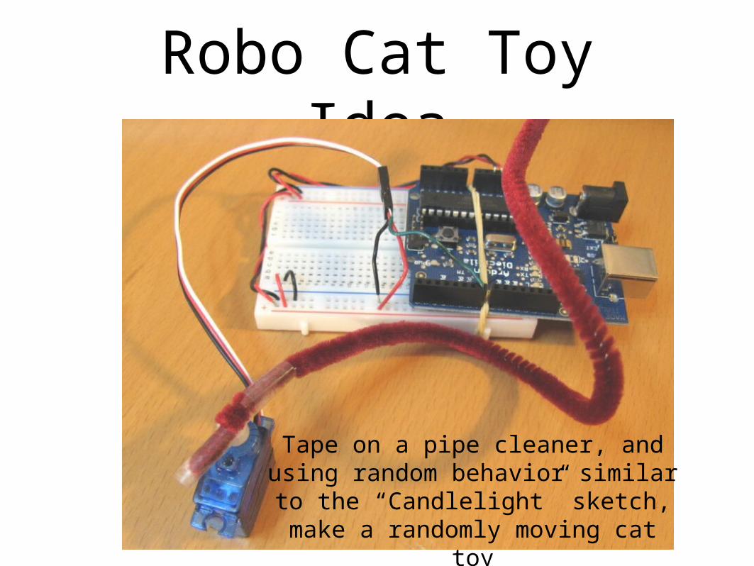
Robo Cat Toy Idea
Tape on a pipe cleaner, and using random behavior similar to the “Candlelight” sketch, make a
randomly moving cat toy

Servo Timing Problems
•Two problems with the last sketch
•When servoPulse() function runs, nothing else can happen
•Servo isn’t given periodic pulses to keep it at position
•You need to run two different “tasks”:
•one to read the serial port
•one to drive the servo
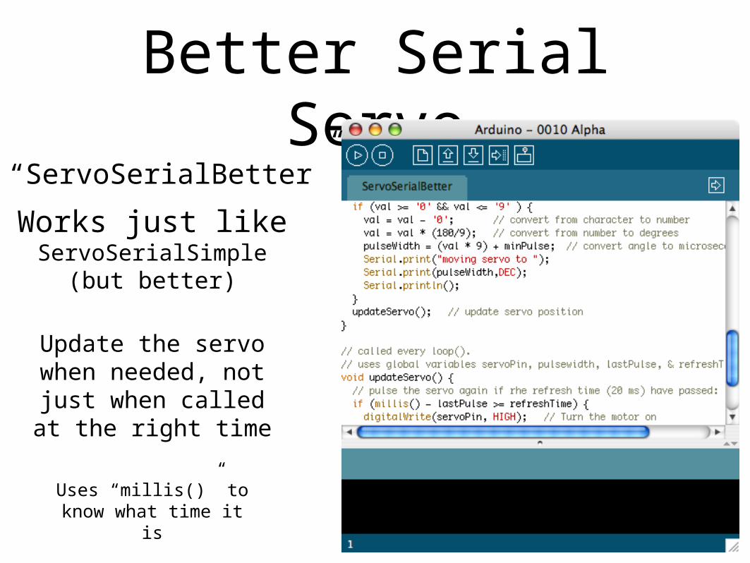
Better Serial Servo
Works just like ServoSerialSimple
(but better)
Uses “millis()” to know what time it is
Update the servo when needed, not just when called at
the right time
“ServoSerialBetter”

Multiple Servos
•The updateServo() technique can be extended to many servos
•Only limit really is number of digital output pins you have
•It starts getting tricky after about 8 servos though

Multiple “Tasks”
• Define your task
• Break it up into multiple time-based chunks (“task slices”)
• Put those task slices in a function
• Use millis() to determine when a slice should run
• Call the functions from loop()
The concept inside updateServo() is useful anytime you need to do multiple “things at once” in an Arduino sketch:

Arduino PWM
•Arduino has built-in PWM
•On pins 9,10,11
•Use analogWrite(pin,value)
• It operates at a high, fixed frequency(thus not usable for servos)
•But great for LEDs and motors
•Uses built-in PWM circuits of the ATmega8 chip -» no software needed
why all the software, doesn’t Arduino have PWM?

Take a Break

Serial Communication
Separate wires for transmit & receive
Asynchronous communication
asynchronous – no clockData represented by setting
HIGH/LOW at given times
Synchronous communication
Synchronous – with clockData represented by setting
HIGH/LOW when “clock” changes
A single clock wire & data wire for each direction like before
Each device must have good “rhythm”
Neither needs good rhythm, but one is the conductor
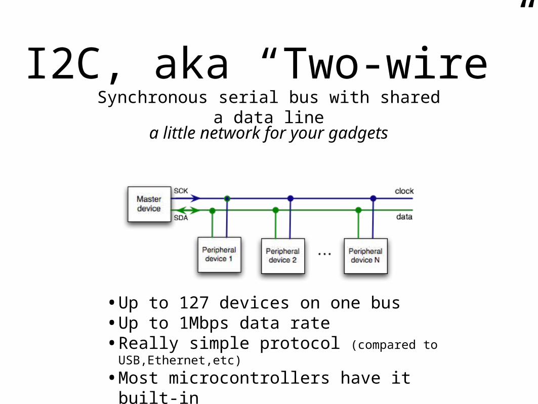
I2C, aka “Two-wire”Synchronous serial bus with shared a data
line
•Up to 127 devices on one bus•Up to 1Mbps data rate•Really simple protocol (compared to
USB,Ethernet,etc)
•Most microcontrollers have it built-in
a little network for your gadgets
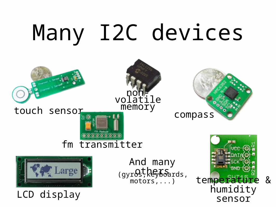
Many I2C devices
touch sensor compass
fm transmitter
non-volatile memory
LCD display
temperature & humidity sensor
And many others(gyros,keyboards, motors,...)
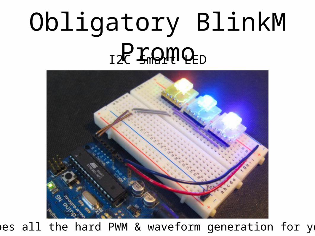
Obligatory BlinkM PromoI2C Smart LED
Does all the hard PWM & waveform generation for you

Nintendo Wii Nunchuck
• Standard I2C interface
• 3-axis accelerometer with 10-bit accuracy
• 2-axis analog joystick with 8-bit A/D converter
• 2 buttons
• $20
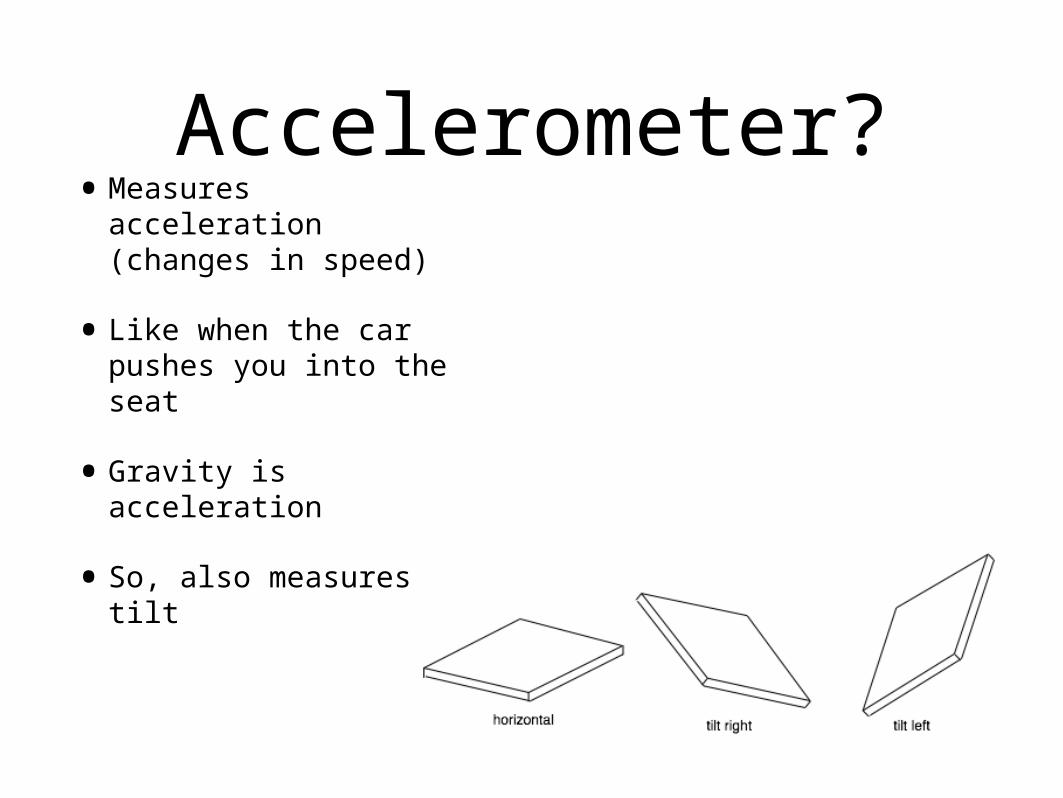
Accelerometer?•Measures
acceleration (changes in speed)
•Like when the car pushes you into the seat
•Gravity is acceleration
•So, also measures tilt
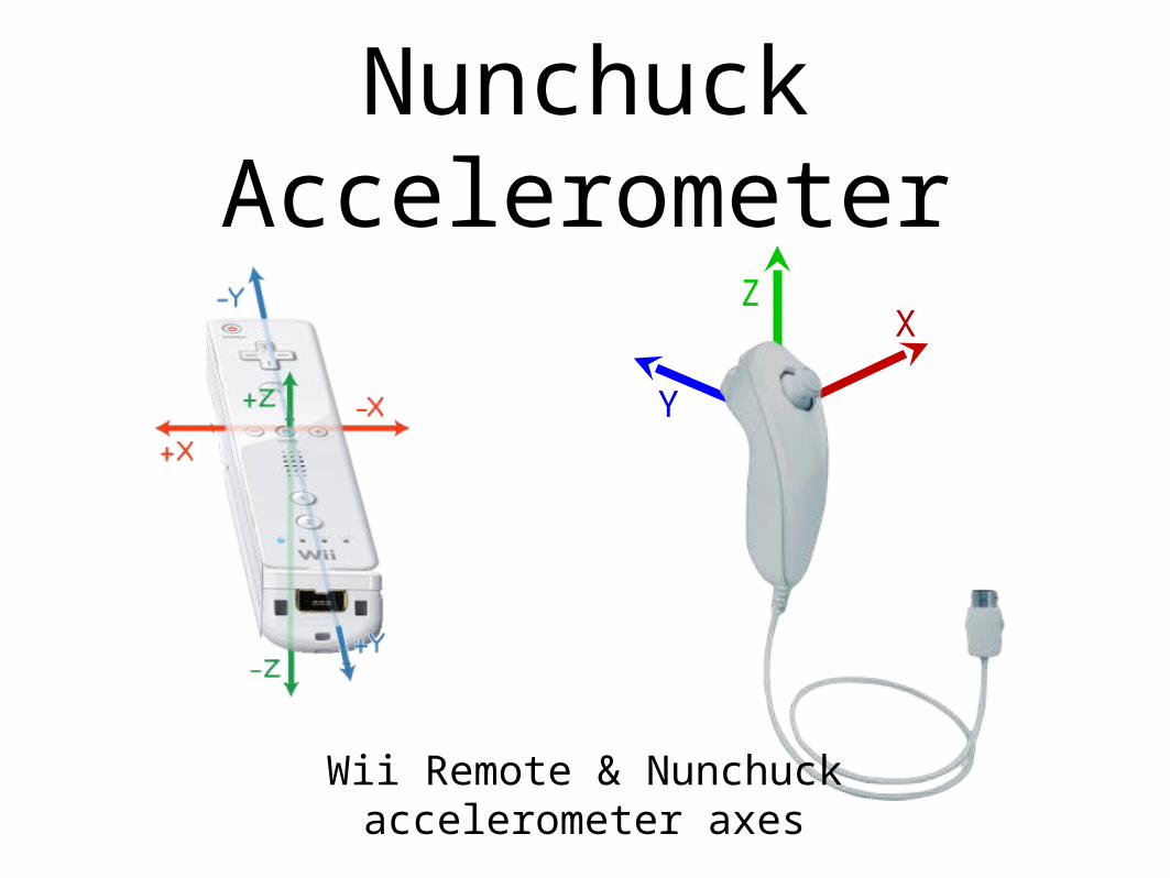
Nunchuck Accelerometer
XZ
Y
Wii Remote & Nunchuck accelerometer axes
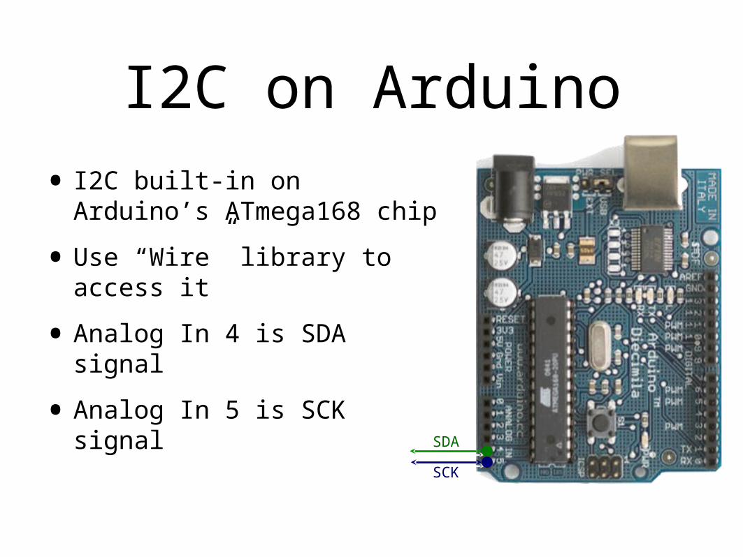
I2C on Arduino
• I2C built-in on Arduino’s ATmega168 chip
•Use “Wire” library to access it
•Analog In 4 is SDA signal
•Analog In 5 is SCK signalSDA
SCK
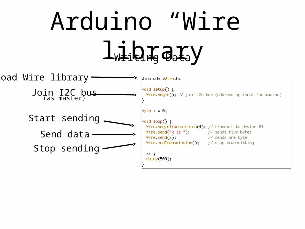
Arduino “Wire” libraryWriting Data
Start sending
Join I2C bus(as master)
Send data
Load Wire library
Stop sending

Arduino “Wire” libraryReading Data
Request data from device
Join I2C bus(as master)
Get data
What kinds of interactions you can have depends on the device you’re talking to
Most devices have several “commands”

Wiring up the NunchuckWe could hack off the
connector and use the wires directly
But instead let’s use this little adapter
board

Wii Nunchuck Adapter
Nunchuck Pinout
(looking into Nunchuck connector)
Adapter Pinout
+V SCK
SDAGND
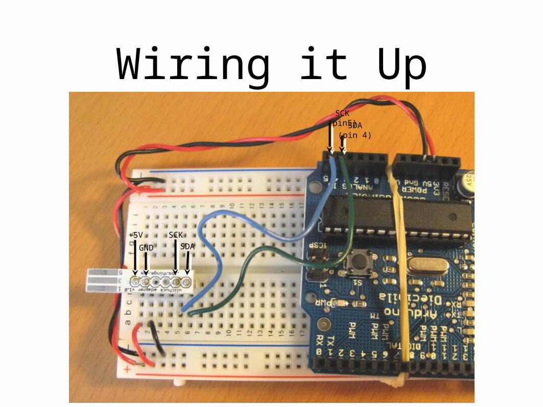
Wiring it Up
GND SDA+5V SCK
SDA (pin 4)
SCK (pin5)

Pluggin’ in the ‘chuck
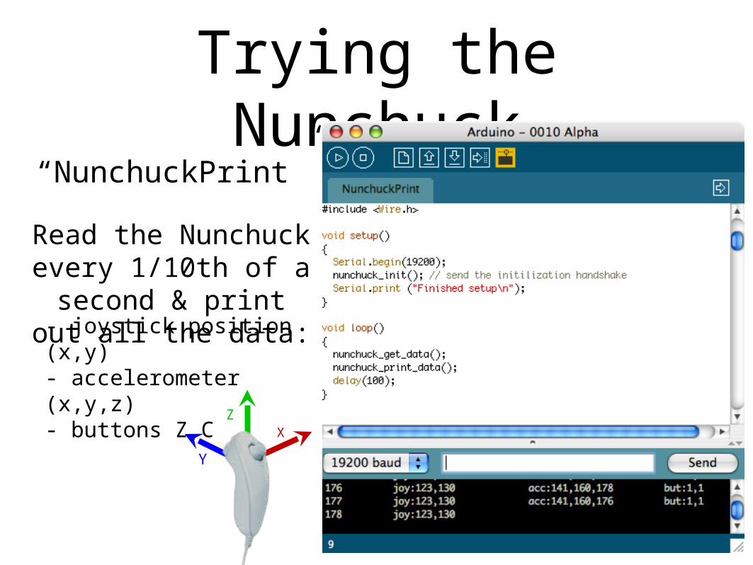
Trying the Nunchuck
“NunchuckPrint”
Read the Nunchuck every 1/10th of a
second & print out all the data:
- joystick position (x,y)- accelerometer (x,y,z)- buttons Z,C
XZ
Y

Adding a Servo
Move the servo by moving your
arm
“NunchuckServo”
You’re a cyborg!
Also press the Z button to flash the pin 13 LED
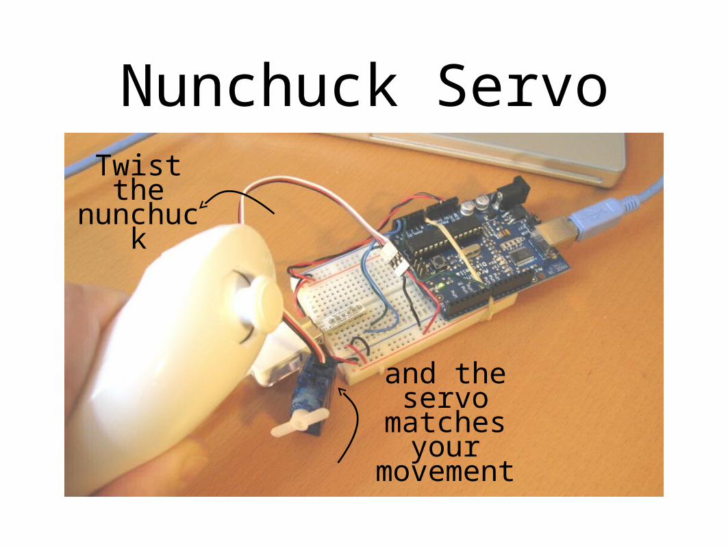
Nunchuck ServoTwist the
nunchuck
and the servo
matches your movement

Segway Emulator
QuickTime™ and aH.264 decompressor
are needed to see this picture.

Going Further
•Servos
•Hook several together to create a multi-axis robot arm
•Make a “servo recorder” to records your arm movements to servo positions and plays them back
•Great for holiday animatronics

Going Further• I2C devices
•Try out some other devices
• Just string them on the same two wires used for the Nunchuck
•Cooperative Multitasking
•Try making a theremin with nunchuck & piezo
•See if previous examples can be made more responsive

Going Further•Nunchuck
• It’s a freespace motion sensor. Control anything like you’re waving a magic wand!
•What about the joystick? We didn’t even get a chance to play with that
•Alternative input device to your computer: control Processing, etc.

SummaryYou’ve learned many different physical building blocks
LEDs
switches/buttonsresistive sensors
motors
piezos
servos
XZ
Y
accelerometers
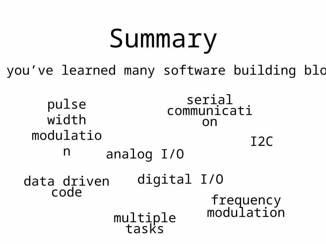
SummaryAnd you’ve learned many software building blocks
pulse width modulation
serial communicati
on
digital I/O
analog I/O
data driven code
frequency modulationmultiple
tasks
I2C

Summary
Hope you had fun and continue playing with Arduino
Feel free to contact me to chat about this stuff