
Biomechancs in Orthodotnics
74
A very good afternoon
-
Upload
sneh-kalgotra -
Category
Education
-
view
1.057 -
download
3
Transcript of Biomechancs in Orthodotnics

A very good afternoon

Seminar Presenatation-Biomechanics in Orthodontics
Under the guidance of : Dr. Mohammad Mushtaq, HOD & GUIDE
By: Sneh Kalgotra, 2nd Year P.G.
Department of Orthodontics & Dentofacial Orthopaedics, GDC&H, Srinagar.

Contents
1. Introduction 2. Newton’s laws of motion.3. Scalors and vectors. 4. Parallelogram principle.5. Centre of mass.6. Centre of gravity 7. Centre of resistance.8. Centre of rotation.9. Moment and moment of force.10.Couple.

11. Moment to force ratio.12. Cue ball priciple, row boat efect, diving board effect.13. Types of tooth movement.14. One couple , two couple system.15. Biomechanics of leveling nad aligning.16. Biomechanicss of space closure.17.Biomechnics of finishing.18. Conclusion.

Why learn about Biomechanics?

Introduction • Orthodontists are biological scientists and have
not always been comfortable with the physical sciences.
• There is no room for the “one step forward, two steps backward” type of treatment mechanics.
It thus behooves the orthodontist to acquire the skills necessary to do the “A directly to B.” type of orthodontic treatment.
A B A B
Biomechanics in Orthodontics. Michael R. Marcotte, 1st Edition

These mechanicl principles are found within the branch of engineering science called as mechanics.
• It is the study of mechanics as it affects the biologic systems. It is the application of mechanics to the biology of tooth movement – BIOMECHANICS.
• Biology + Mechanics = Bio-mechanics.
It becomes important for Orthodontists to think, understand and apply basic principles of mechanics in a common sense manner.Biomechanics in Orthodontics. Michael R. Marcotte, 1st Edition

Walking on staircase
The elbow joint and bending
Knee joint
Body balancing as a whole

Scalar: When a physical property ( Weight, temperature ,force) has only magnitude , its called a scalar quantity.
( E.g.. A force of different magnitude such as 20gm,50gm etc)
Vector: When a physical property has both magnitude and direction its called a vector quantity.
(E.g.. A force vector characterized by magnitude, line of action, point of origin and sense)

Newton’s laws of motion
An object at rest tends to stay at rest and an object in motion tends to stay in motion unless acted upon by an unbalanced force.
1st law

Newton’s Second Law
Force equals mass times acceleration.
F = ma

One rock weighs 5 Newtons.The other rock weighs 0.5 Newtons. How much more force will be required to accelerate the first rockat the same rate as thesecond rock?
Ten times as much

Newton’s 3rd Law• For every action there is an equal
and opposite reaction.
Book toearth
Table tobook

• A bug with a mass of 5 grams flies into the windshield of a moving 1000kg bus.
• Which will have the most force?
• The bug on the bus• The bus on the bug

Force• It is defined as an act upon a body that changes
or tends to change the state of rest or motion of the body. Force is a vector it has both magnitude and direction.
• The forces are indicated by straight arrows.

• Vectors can also be resolved into components.

Resultant of forces
A Force Proportional To The Length Ab Operates In The Direction Ab;A Second Force Proportional To The Length Ac Operates In The Direction Ac;The Resultant Force Operates In The Direction Ad And Is Proportional To The Length Ad.This Device For Calculating The Total Effect Of Two Forces Is Called The Parallelogram Law Of Forces.
A
b
C
d

CENTER OF MASS:
• Each body has a point on its mass , which behaves as if the whole mass is concentrated at that single point. We call it the center of mass in a gravity free environment.
• The same is called center of gravity in an environment where gravity is present.
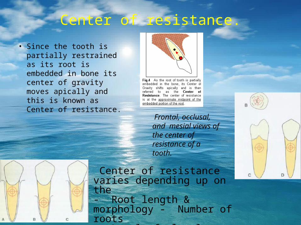
Center of resistance.
• Since the tooth is partially restrained as its root is embedded in bone its center of gravity moves apically and this is known as Center of resistance.
Frontal, occlusal, and mesial views of the center of resistance of a tooth.
Center of resistance varies depending up on the - Root length & morphology - Number of roots- Level of alveolar bone support.

Center of resistance for A) a two-tooth segment and B) a maxilla C) Center of resistance of Maxillary molar.
A B C
Biomechanics in clinical Orthodontics. Ravindra Nanda, 1st Edition

CENTER OF ROTATION
• It may be defined as a point about which a body appears to have rotated as determined from its initial to final positions.
• A simple method of determining a center of rotation. Draw the long axis of the tooth in its initial and final positions; we will see that both these lines intersect at a point. This is the point around which the tooth rotates and is called center of rotation.

• The centre of rotation can be at the centre of resistance,apical to it,at the root apex or at infinity.

TYPES OF TOOTH MOVEMENT POSITION OF THE CENTER OF
ROTATION
A. Translation
B. Uncontroued tipping
C. Controlled tipping
D. Root movement of torquing
Lies at infinity
Slightly apical to center of
resistance
Apex of root
Incisal or occlusal edge

Moment of the force• The moment of the
force is the tendency for a force to produce rotation. It is determined by multiplying the magnitude of the force by the perpendicular distance of the line of action to the center of resistance
• The force is not acting through the Cres
Unit– Newton. mm
Moment :Defined as a tendency to rotate.

• The direction of moment of force can be determined by continuing the line of action around the Cres.

Couple
A couple consists of two forces of equal magnitude, with parallel but non colinear lines of action and opposite senses.
• The result is a moment with no net force.
• The object rotates about it’s centre of resistance regardless of the point of application of the couple.

Couple-clinical point• When the tooth is embedded within the alveolar
bone,a couple can be applied only on the exposed part of the tooth.Various tooth alignment procedures can be achieved by this couple mechanism. Depending on the plane in which the couple is acting this rotational tendency is called
a.Rotation{first order} b.Tipping{second order} c.Torque{third order}

M/F (moment to force ratio) is the relationship between the force and the counter balancingcouple that determines the type of tooth movement
The ratio of the counter-balancing moment produced to the net force that is applied to the tooth will determine the type of tooth movement that will occur.

Force applied on a tooth
Crown moves more than root
To maintain the inclinationOf the tooth
Overcome the moment Created by the force applied to the crown
Counter moment

To maintain axial inclination
Apply the force close to the center of resisitance
Create a 2nd moment In the direction opposite to the first
Practical difficulty
Power arm
Counter moment
Tooth remain uprightAnd move bodily

M/F 5 : 1 Uncontrolled tipping
M/F 8 : 1 Controlled tipping
M/F 10 : 1 Translation
M/F >10 : 1 Root movement
MOMENT TO FORCE RATIO FOR VARIOUS TOOTH MOVEMENTS

TORQUE
A rectangular wire ina rectangular slot
Generate the momentof a couple necessaryto control rootposition
Torque acting as the counter moment
Bracket system
Clinical implication

TIP In the PAE bracket system, the tip incorporated into the bracket acts as the counter moment in the mesio distal direction
This prevents the tipping of the tooth in the mesio distal direction.
Bracket system

The line of action of the force passes through the center of resistance. This tooth will translate, even though the point of attachment to the tooth is at the bracket.
Principle of power arm
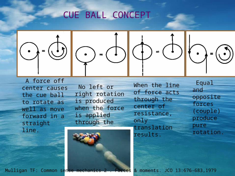
A force off center causes the cue ball to rotate as well as move forward in a straight line.
No left or right rotation is produced when the force is applied through the center of the cue ball.
When the line of force acts through the center of resistance, only translation results.
CUE BALL CONCEPT
Equal and opposite forces (couple) produce pure rotation.
Mulligan TF: Common sense mechanics 2 . Forces & moments. JCO 13:676-683,1979

If the bends produce equal angular relationships (A), the net forces are zero. If unequal (B), net forces occur.
ROW BOAT EFFECT
Mulligan TF: Common sense mechanics 2 . Forces & moments. JCO 13:676-683,1979

With a constant tipback angle, the deflection doubles as the wire length doubles, the force is reduced to one fourth
When the length of the diving board is doubled, only one-eighth the force is required to produce the same amount of deflection. B. The same force acting at twice the length will produce eight times as much deflection.
DIVING BOARD CONCEPT
Mulligan TF: Common sense mechanics 2 . Forces & moments. JCO 13:676-683,1979

TOOTH MOVEMENTS.• Uncontrolled tipping.• Controlled tipping.• Translation.• Root movement.• Pure rotation

UNCONTROLLED TIPPING
• When only a force is applied at the bracket to move a tooth ,the equivalent force system at the center of resistance is force plus the moment that will tip the crown in the direction of force.as the counteracting moment is absent, the crown moves further than the center of resistance and the apex moves in the opposite direction.
• When the moment to force ratio is zero, the center of rotation is apical to the center of resistance.

CONTROLLED TIPPING.• To counteract the tendency for tipping a couple
can be applied intentionally at the bracket to produce a moment of less magnitude in the opposite direction.the moment-to-force ratio of 7:1 is applied at the bracket,the equivalent force system at the center of resistance is a force to move the tooth plus a small net tendency for the crown to tip in the direction of the force.
• Therefore ,the center of rotation,when the moment-to-force ratio is 7:1, is at the apex of the tooth and only crown movements occur.

TRANSLATION
• To counteract the tendency for tipping, a couple can be applied intentionally to produce a moment of equal magnitude in the opposite direction.when a moment –to –force ratio of 10:1 is applied to the bracket ,the equivalent force system at the center of resistance is a single force with no net moment.
• In the pure translation, the center of rotation is considered to be at infinity, because no rotation occurs.

ROOT MOVEMENT.• When the counter moment applied intentionally at
the bracket is more than the moment of force , the root moves in the direction of force but the crown tips in the opposite direction.when the moment-to –force ratio of 13:1 is applied at the bracket,the equivalent force system at the center of resistance is a force to move the tooth plus a small net tendency for the root to tip in the direction of force.
• The center of rotation ,when the moment to force ratio is 13:1,is at the crown of the tooth and only root movements occur.

PURE ROTATION.• If only a couple ,and no force is applied to a tooth
the tooth will rotate around it’s centre of resistance and the tooth will not translate. because the action of a couple does not depend on it’s point of application,a pure moment always acts at the center of resistance.
• The forces of a couple cancel out any tendency for the center of resistance of the tooth to move but the moment produced by the couple causes the tooth to rotate the moment-to force ratio is infinite and the center of rotation coincides
with the center of resistance

Biomechanical classification of orthodontic appliances
• Equal and opposite force system.• One couple appliance system.• Two couple appliance system.

Equal and opposite force system.
• Simplest orthodontic appliance ,an elastic band stretched between two points of attachment is the best example. This produces force of equal magnitude on either end but opposite direction.

ONE COUPLE APPLIANCE SYSTEMS.
• One end of the appliance experiences couple and the other end is tied as a point contact. It is statically determinate because the magnitudes of the forces and moments produced can be determined clinically after the appliance is inserted into the bracket / tube. This can be done by inserting the appliance into the bracket and measuring the force required to activate the wire to the site it will be tied as a point contact.

Two couple appliance system.
• The both the ends of the appliance are engaged into attachments{brackets or tubes}.A couple may be generated by the wire at either or both attachment sites. The force systems produced by two couple appliances cannot be measured clinically and so they are referred as statically indeterminate.

• Variety of combinations of two- bracket systems and their force systems
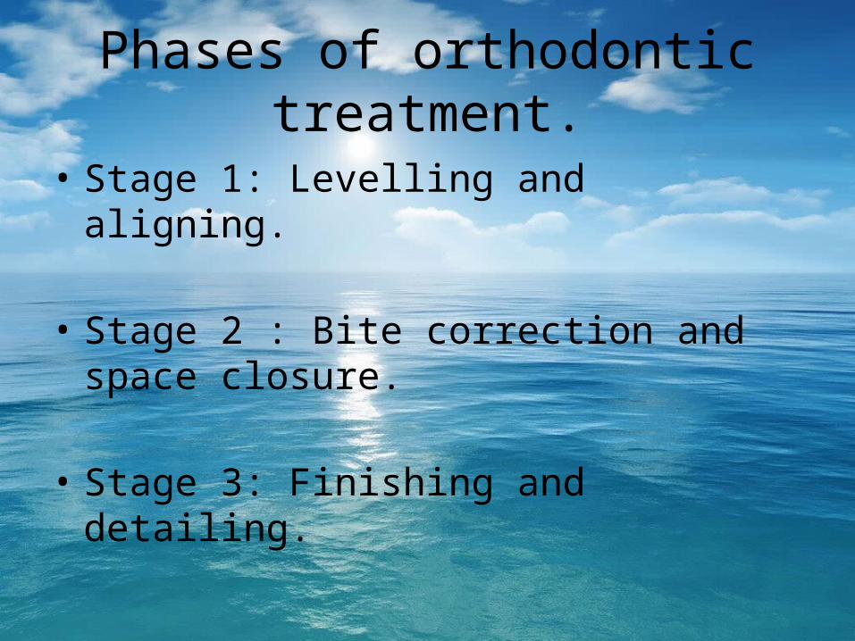
Phases of orthodontic treatment.
• Stage 1: Levelling and aligning.
• Stage 2 : Bite correction and space closure.
• Stage 3: Finishing and detailing.
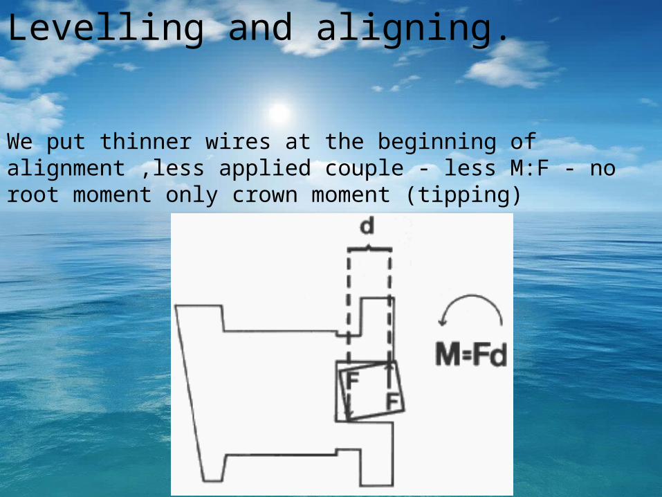
Levelling and aligning.
We put thinner wires at the beginning of alignment ,less applied couple - less M:F - no root moment only crown moment (tipping)

The 2 central incisors are rotatedmesial in creating a symmetric V geometry. Thedesired corrective force system involves 2 equaland opposite moments as illustrated
Semin Orthod 2001;7:16-25.

The force system developed by inserting a straight wire into the brackets ofthe 4 anterior teeth will create counterclockwise moments on the 2 central incisors as well as lingual movement of the left central incisor and labial movement of the right central incisor. The initial geometry is not favorable for alignment.
Semin Orthod 2001;7:16-25.

shows a lingually placed right lateral incisor. In this case, the geometric relationship between the right lateral and central incisors is a step geometryand the placement of a straight wire into the brackets of the 4 anterior teeth will align the teeth and also shift the midline to the right side
Semin Orthod 2001;7:16-25.

In the maxillary arch shown in Figure, the relationship between the central incisors is a step geometry and an asymmetric V geometry is observed between the central and lateral incisors on the right side. Analysis of the force system shows that, although correction of the 2 central incisors will occur asa result of straight wire placement, the right lateral incisor will be displaced labially, which is an undesirable side effect . Semin Orthod 2001;7:16-25.

During extrusion of a high canine unilaterally. Figure A shows theforce system generated by the placement of a straight wire through a high maxillary right canine. The canine will extrude as desired, but the lateral incisor and first premolar on that side will intrude and tip toward the canine space. An open bite may result on that side of the arch, and the anterior occlusal plane will be canted up on the right side.
Semin Orthod 2001;7:16-25.
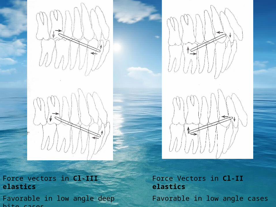
Force vectors in Cl-III elastics
Favorable in low angle deep bite cases
Force Vectors in Cl-II elastics
Favorable in low angle cases

SPACE CLOSURE
ANCHORAGE CLASSIFICATION.
Group A anchorage. This category describes the critical maintenance of the posterior tooth position. Seventy-five percent or more of the extraction space is needed for anterior retraction.

Group B anchorage. This category describes relatively symmetric space closure with equal movement of theposterior and anterior teeth to close the space. This is often the least difficult space closure problem.

Group C anchorage. This category describes "noncritical"anchorage. Seventy-five percent or more of the space I closed by movement of the posterior teeth.


Ideal space closure

Ideal force system for group A space closure. For perfect maintenance of the posterior anchorage, no forces should act on the posterior teeth; only a force system resulting in anterior translation is desired. This force system cannot exist unless all the anchorage units are extra oral or in the opposite arch.

• In A the blue arrow represents an additional force acting on the anterior teeth (i.e. Class II elastics or J-hook headgear). In B the blue arrow represents the force from a headgear acting on the posterior teeth. In both cases the change in the force magnitude results in a lower moment/force ratio on the anterior teeth and an increased moment/force ratio on
the posterior teeth.

• Force system for group B space closure. Translation of the anterior and posterior teeth is required to achieve ideal space closure. A moment/force ratio approximating 10/1 is needed for translation.

• The difficulty of group C anchorage mirrors that of group A anchorage. The difference is that the anterior teeth become the effective "anchor unit". Therefore, the anterior moment is of greater magnitude and the vertical force side effect is an extrusive force on the anterior teeth. Due to the difficulty of this type of space closure in the lower arch, extraction treatment should be re-evaluated carefully and great awareness of the possible side effects is needed.

Finishing
• The major factors involved in achieving this proper anterosuperior incisor inclination are the bracket and wire coupling.
• A specific archwire with a medium-to-low load deflection rate (such as a 0.017 x 0.025) can be selected.

• After the third-order objectives are met, second-order movements are addressed. Adjustments in this plane also take a significant amount of time because they also involve root correction. To achieve second-order objectives, either
the same 0.016 x 0.022 beta-titanium or steel round archwire can be used, providing all the thirdorder objectives have been met.

• The final step in finishing is the correction of first-order problems. Usually these problems are obvious clinically and can be corrected quickly. Tn many instances, only small correction bends in the archwire are needed. Correction can also be achieved with auxiliary plastic rotation wedges on the brackets, or by making small bends in either the 0.016 x 0.022 beta-titanium or 0.016 steel archwire.

BIOMECHANICS-CORE OF CLINICAL PRACTICE• Optimization of tooth movement.• Anchorage control.• Selection of wires, brackets and clinical devices.• Explanation and evaluation of treatment results.• Research.• Minimization of tissue destruction.• Reduction of need for patient cooperation.• Development and evaluation of new appliances.• Knowledge transfer from appliance to appliance.

Conclusion
• The choice of appliances and techniques used by practitioners varies radically among individuals but the fundamental forces and moments they produce are universal.
• Appliance will always act according to the LAWS OF PHYSICS. Understanding the basic biomechanical principles involved in effective controlled tooth movement makes the final outcome more predictable and consistent.

• Newton’s third law states that every action has a equal and opposite reaction.
• Its important to keep this concept in mind working with any appliance system and give adequate importance to take steps to prevent the adverse effects.
• In orthodontic terms, the understanding of the moment and the application of the necessary counter moment to bring about the optimal tooth movement is the key to successful treatment results.
• An application of little bit of common sense can work wonders for the treatment outcome.

REFFERENCES
1. Smith RJ, Burstone CJ: Mechanics of tooth movement. AJO 85:294-307,1984.
2. Burstone CJ, Koenig HA: Creative wire bending- The force system from step & V bends. AJO DO 93(1):59-67,1988.
3. Burstone CJ, Koenig HA: Force system from the ideal arch. AJO 65(3):270-289,1974.
4. Demange C: Equilibrium situations in bend force system. AJO DO98(4):333-339,1990.
5. Issacson RJ, Lindauer SJ, Rubenstein LK: Moments with edgewise appliance e: Incisor torque control. AJO DO 103(5):428-438,1993.
6. Koing HA, Vanderby R, Solonche DJ, Burstone CJ: Force system for orthodontic appliances: An analytical & experimental comparison. J Biomechanical Eng102(4):294-300,1980.
7. Kusy RP, Tulloch JFC: Analysis of moment/force ratio in the mechanics of tooth movement. AJO DO 90; 127-131,1986.
8. Nanda R, Goldin B: Biomechanical approaches to the study of alteration of facial morphology. AJO 78(2):213-226,1980.

9. Vanden Bulcke MM, Burstone CJ, Sachdeva RC , Dermaut LR: Location of center of resistance for anterior teeth during retraction using the laser reflection technique. AJO DO 91(5):375-384,1987.
10. Vanden Bulcke MM, Dermaut LR, Sachdeva RC, Burstone CJ: The center of resistance of anterior teeth during intrusion using the laser reflection technique & holographic interferometry. AJO DO 90(3): 211-220,1986.
11. Mulligan TF: Common sense mechanics 2 . Forces & moments. JCO 13:676-683,1979.
12. Siatkowski RE: force system analysis of V-bend sliding mechanics. JCO 28(9):539-546,1994.
13. Tanne K, et al: Moment to force ratios & the center of rotation. AJO 94:426-431,1989
14. The basics of orthodontic mechanics. Semin Orthod 2001;7:2-15
15. Leveling & aligning: Challenges & Solutions Semin Orthod 2001;7:16-25.
16. Biomechanics in clinical Orthodontics. Ravindra Nanda, 1st Edition
17. Biomechanics in Orthodontics. Michael R. Marcotte, 1st Edition

• Thank you
Sneh Kalgotra2nd year P.G.


