Biologically inspired molecular machines driven by light
25
OPEN ACCESS Biologically inspired molecular machines driven by light. Optimal control of a unidirectional rotor To cite this article: Guillermo Pérez-Hernández et al 2010 New J. Phys. 12 075007 View the article online for updates and enhancements. You may also like Effective system of learning for engineers M F Guskova, P F Sterlikov and F F Sterlikov - ICT literacy with google suite for education (GSFE) in junior high school with different academic abilities K Insani, Suratno and I Farisi - Dynamic method of control of weight of cargo transported by vehicle A V Egorov, S V Dorohin, A V Lysyannikov et al. - Recent citations Unidirectional Rotary Motion in Isotopically Chiral Molecular Motors: A Computational Analysis Jun Wang et al - Nuclear spin blockade of laser ignition of intramolecular rotation in the model boron rotor B13+11 Thomas Grohmann et al - From coherent quasi-irreversible quantum dynamics towards the second law of thermodynamics: The model boron rotor B13+ Dongming Jia et al - This content was downloaded from IP address 157.25.173.210 on 20/01/2022 at 15:22
Transcript of Biologically inspired molecular machines driven by light

OPEN ACCESS
Biologically inspired molecular machines driven bylight. Optimal control of a unidirectional rotorTo cite this article: Guillermo Pérez-Hernández et al 2010 New J. Phys. 12 075007
View the article online for updates and enhancements.
You may also likeEffective system of learning for engineersM F Guskova, P F Sterlikov and F FSterlikov
-
ICT literacy with google suite for education(GSFE) in junior high school with differentacademic abilitiesK Insani, Suratno and I Farisi
-
Dynamic method of control of weight ofcargo transported by vehicleA V Egorov, S V Dorohin, A V Lysyannikovet al.
-
Recent citationsUnidirectional Rotary Motion in IsotopicallyChiral Molecular Motors: A ComputationalAnalysisJun Wang et al
-
Nuclear spin blockade of laser ignition ofintramolecular rotation in the model boronrotor B13+11Thomas Grohmann et al
-
From coherent quasi-irreversible quantumdynamics towards the second law ofthermodynamics: The model boron rotorB13+Dongming Jia et al
-
This content was downloaded from IP address 157.25.173.210 on 20/01/2022 at 15:22

T h e o p e n – a c c e s s j o u r n a l f o r p h y s i c s
New Journal of Physics
Biologically inspired molecular machines driven bylight. Optimal control of a unidirectional rotor
Guillermo Pérez-Hernández1, Adam Pelzer2, Leticia González1
and Tamar Seideman2,3
1 Friedrich-Schiller-Universität Jena, Institut für Physikalische Chemie,Helmholtzweg 4, D-07743 Jena, Germany2 Department of Chemistry, Northwestern University, 2145 Sheridan Road,Evanston, IL 60208-3113 USAE-mail: [email protected]
New Journal of Physics 12 (2010) 075007 (24pp)Received 17 December 2009Published 8 July 2010Online at http://www.njp.org/doi:10.1088/1367-2630/12/7/075007
Abstract. We investigate the extent to which unidirectional intramoleculartorsional motion can be created in an oriented bicyclic model system drivensolely by laser light. We apply the machinery of quantum control via specificallytailored laser pulses to induce such motion, eliminating the need for the thermallyconstrained steps conventionally used in molecular motor systems. Our approachdoes not rely on specific details of the potential surfaces to create a preferreddirection. Rather, we use matter–field interaction and the tools of coherentoptimal control to create a wave packet with nonzero angular momentum amongunbound torsional states on an excited electronic surface. Analysis of the resultsof the control algorithm provides general insight into when and how optimalcontrol theory can find solutions that could not be generated through simpleintuitive schemes. We find that, under constrained polarization, the controlalgorithm reduces to a simple intuitive coherent control strategy wherein a firstIR pulse creates a non-stationary wave packet on the ground surface and asubsequent UV pulse transfers it to the excited state. Allowing for polarizationshaping, however, we find new control routes that go beyond the intuitivescheme.
3 Author to whom any correspondence should be addressed.
New Journal of Physics 12 (2010) 0750071367-2630/10/075007+24$30.00 © IOP Publishing Ltd and Deutsche Physikalische Gesellschaft

2
Contents
1. Introduction 22. Model and methods 4
2.1. Model system. Spectroscopy and quantum chemistry . . . . . . . . . . . . . . 42.2. Eigenfunctions and eigenenergies . . . . . . . . . . . . . . . . . . . . . . . . 62.3. Time-dependent nuclear dynamics . . . . . . . . . . . . . . . . . . . . . . . . 92.4. Optimization of the laser pulse . . . . . . . . . . . . . . . . . . . . . . . . . . 10
3. Results 113.1. Linear polarization . . . . . . . . . . . . . . . . . . . . . . . . . . . . . . . . 113.2. Polarization shaping . . . . . . . . . . . . . . . . . . . . . . . . . . . . . . . . 17
4. Conclusion 22Acknowledgments 23References 23
1. Introduction
The development of molecular machines has grown, during the past two decades, into an activeand diverse subdiscipline of nanoscience. The understanding of natural molecular mechanicalmotions has inspired researchers in chemistry, physics and materials science to create syntheticsystems with similar capabilities with the goal of assembling complex machines from molecularcomponents. Artificial nanoscale devices have taken the form of molecular switches [1],propellers [2], muscles [3], gears [4], shuttles [5] and rotors [6], to name but a few of manyimaginative examples (for a comprehensive monograph, see [7]).
Conventional molecular machines are driven incoherently, as an ensemble, for instanceby changes in temperature [8], pH-value [9], redox potential [10] or light [11]–[13]. Themore recent literature on current-driven dynamics in molecular-scale electronics [14]–[18], hasillustrated the possibility of driving molecular machines individually, on a single device level, inthe dry state. Here coherence is maintained (in the complete electronic + vibrational space) butthe opportunities for control are limited, as the driving force is electronic. Together, the earlyresearch on incoherently driven, light-triggered molecular rotors [11]–[13] and the recent workon individually addressed, current-driven molecular machines in junctions [14]–[18] suggestthe application of control theory to drive molecular motors with coherent light.
The latter field, the control of molecular systems with coherent light sources, has beenextensively reviewed [19]–[28] and is well understood. Concepts and techniques of coherentcontrol have been applied to problems as diverse as atomic physics and gas-phase moleculardynamics, solid-state physics and semiconductor device technology, solution chemistry andbiology. Underlying the success of coherent control is the understanding that the coherenceproperties of laser light can be imprinted on the quantum state of the system through thelight–matter interaction, along with the development of light sources that allow precise controlover the spectral composition and phase properties of the electromagnetic field.
Among coherent control approaches, optimal control theory (OCT), wherein a systematicprocedure is employed to determine the field properties that optimize a desired systemobservable, has been gaining increasing popularity. The success of this class of techniques owesto their rigorous theoretical understanding [24, 29, 30], the increasing power of computational
New Journal of Physics 12 (2010) 075007 (http://www.njp.org/)

3
a)
BCH
b)
Figure 1. (a) Bicyclohexylidene (BCH). (b) So-called first generation molecularrotors, adapted from [6].
systems, and the advance of modern pulse shaping technologies [31]–[41]. The extent to whichOCT can unravel control routes that could not be designed by simple intuitive schemes, however,has been a matter of controversy.
Here we apply OCT to develop a new form of molecular machines, one that marries theattractive features of conventional light-driven machines [42, 43] and individually triggered,current-driven machines [14]–[16], [18]. Specifically, we consider the problem of creatingunidirectional intra-molecular rotation in a simple (but general) oriented model system,representing a class of biological molecules. A number of previous calculations have illustratedunidirectional torsion with short linear or circularly polarized pulses. Hoki et al [44, 45] showthat linearly polarized pulses can be used to create unidirectional torsion in a chiral, randomlyoriented system with an asymmetric ground state potential surface, via state ladder climbing,while circularly polarized pulses must be used to achieve the same effect in an oriented chiralmolecule [44]. In these cases, the asymmetry of the potentials creates a preferred directionof motion. Yamaki et al [46] apply OCT to the same system to show that a single linearlypolarized shaped pulse can make use of the asymmetries of both the ground and the excitedstate surfaces to drive unidirectional motion in either direction, and that the mechanism can berationalized as a simple pump–dump process. An intuitive procedure based on a sequence ofan IR and a UV unshaped pulses, with which wave packet localization on the ground surfaceis followed by projection onto the excited surface, was also shown to successfully achieveunidirectionality [47].
Our goal in the present work is three-fold. Firstly, we explore the possibility of usingcoherent control tools and concepts to drive sustained, unidirectional torsion in a symmetricsystem. Secondly, we ask to what extent OCT can devise control routes that go beyond intuitiveschemes, rather than reduce to a simple pulse sequence that could have been guessed aheadof the optimization. Thirdly, and most interestingly, we illustrate the potential of polarizationshaping as an efficient way of breaking symmetry and producing unidirectional motions.
As a simple but general model system we choose 1, 1′-bicyclohexylidene (BCH). Thissimple olefin, shown in figure 1(a), is used as a 1D model of a class of much more complicatedmolecular rotors [6, 48, 49] (see figure 1(b)), that nonetheless shares their essential structuralmotives. Research in the field of conventional molecular machines has achieved intramolecularrotation in these systems through a series of steps consisting of a thermally induced inversion
New Journal of Physics 12 (2010) 075007 (http://www.njp.org/)

4
of helicity followed by a photochemically induced cis–trans-isomerization of the central C Cdouble bond. Our goal in the present contribution is to induce continuous unidirectional torsionin BCH coherently, solely through the interaction with a laser pulse. We are specificallyinterested in the case where the potential energy surfaces (PESs) and dipole moments alongthe torsional coordinate are totally symmetric. As in the experiments of [49, 50], our system isoriented and fixed onto a surface. Hence unidirectional motion induced in the molecular frameis not averaged out in the laboratory frame. We recognize the complexity of realistic moleculesand hence begin our study with an ab initio calculation of the underlying PESs and dipolefunctions at a high level of the theory. Our calculations omit inter-nuclear vibrational motionsand focus only on the torsional states of the ground and first excited state Hamiltonians.
In the following section, we first provide details of the electronic structure and spectroscopyof BCH and next outline our methods of time propagating the wavefunction and our controlapproaches. Section 3.1 examines the results of calculations performed with linear polarizationalone. Finally, in section 3.2 we illustrate the potential of polarization optimization in thiscontext. Our conclusions are summarized in the final section.
2. Model and methods
2.1. Model system. Spectroscopy and quantum chemistry
The nature of the electronically excited states of BCH has been the subject of discussion forseveral years, both experimentally [51]–[54] and theoretically [55]–[60]. Spectroscopically, oneobserves bands centered about 5.95 and 6.82 eV in the vapor phase [51], 5.95 and 6.32 eVin the crystalline phase [51] and 6.01 and 6.94 eV in n-pentane solution [52]. Whereas onestrong absorption band may have been expected in the BCH UV-spectrum (corresponding tothe π → π∗-transition) [61], the appearance of two strong bands in the gas phase as wellas in condensed phases is surprising. The π → π∗-bands of the anti- and syn-isomers werenumerically found identical [57]. Furthermore, the observation of two bands in the UV-spectrumof BCH crystal, where only the anti-isomer is present [51], rules out the possibility that the twoπ → π∗-bands result from two different isomers that absorb at different energies. Whereas otherpossible valence excitation types have been proposed experimentally (σ → σ ∗ [51] and π →
(CH)2π∗ [52]) and numerically (π → σ ∗ [58]), the Rydberg nature of this band was illustrated
only recently, first experimentally [54] and later numerically [59]. Its anomalous intensity wasattributed to valence mixing [59] of the π → π∗-state and the π , Rydberg manifold of states. Asubsequent study provided a somewhat different explanation [60], based on calculation of boththe π → π∗-state and the first Rydberg (π → 3sR) state within multiconfigurational completeactive space self-consistent-field second-order perturbation theory in its multi-state version(MS-CASPT2). The main conclusion of [60] is that no valence mixing between the π → π∗-state and the π → 3sR-state occurs in the excited state wavefunctions. The π → π∗-band originis located beyond the vertical excitation energy of the Rydberg band. Thus, much of the apparentRydberg intensity can be ascribed to the underlying, strongly absorbing valence-π → π∗-band.Details can be found in [60].
In the present work we compute adiabatic PESs and transition and permanent dipolemoments surfaces for the ground electronic state and the first excited electronic singlet statealong the BCH torsional coordinate β, starting in the anti-BCH MP2/6-31G∗ equilibriumgeometry (figures 2, 3), whereas the other coordinates are kept fixed at their equilibriumconfigurations. Our results are summarized in figure 4. The ground state potential (V1) shows
New Journal of Physics 12 (2010) 075007 (http://www.njp.org/)

5
anti-BCH syn-BCHC2h C2v
Figure 2. Anti- and syn-BCH.
X
Y
Z
Figure 3. Ball-and-stick diagram of oriented anti-BCH. The curved arrowindicates the torsional angle β. Carbon atoms defining the dihedral angle areshown as dark gray balls.
0.00
0.05
0.10
0.15
0.20
0.25
V /
Eh
V1
V2
a)
1π 2πβ / rad
0
μx11
μy11
μz11
-0.3
-0.2
-0.1
0
0.1
0.2
μ 11
/ a0e
0
b)
0 1π 2πβ / rad
-2
-1.5
-1
-0.5
0
0.5
1
1.5
2
0 1π 2π
μ 12
/ a0e
0
β / rad
μx12
μy12
μz12
c)
Figure 4. Potential energy curves (a), permanent dipole functions(b) and transition dipole functions (c) computed at the MS-CASPT2/SA(12)-CASSCF/ANO-L-Rydberg level of theory [60].
minima at β = 0 (anti-conformation) and π (syn-) with transition states at β = π/2 and 3π/4.The first excited state (V2) shows the opposite topology, with a barrier of about 25 kcal mol−1 atβ = π , while minima are observed for β = π/2 and 3π/4. As determined in [60], at the anti-conformation using C2h symmetry conditions, V2 has π → 3sR character, while the π → π∗-state is higher in energy (V3). In calculations without symmetry considerations, both states mixand therefore the PESs for the π → 3sR and π → π∗ states show the same topological profile;accordingly, both states are bright. For simplicity, in this paper we have chosen the lowest-lyingadiabatic state (V2), assuming that the dynamical results would vary at most little if the V3 statewas chosen.
New Journal of Physics 12 (2010) 075007 (http://www.njp.org/)

6
02.0E-03
05.0E-03
10.0E-03
14.0E-03
0 2 4 8 100 2 4 6 8
syn-BCHanti-BCH
syn-BCHanti-BCH
ν ν’
a) b)
E /
Eh
Figure 5. (a) Lowest ten eigenvalues of the ground state Hamiltonian. (b) Theeigenvalues of panel (a) sorted into syn and anti manifolds. In panel (b), theordinate shows the number of nodes in the state corresponding to the showneigenvalue.
2.2. Eigenfunctions and eigenenergies
The torsional eigenfunctions and eigenenergies of BCH, {8ν, Eν}, were computed bydiagonalization of the field free torsional Hamiltonian
H(β)= T (β)+ V (β)
=
−1
2Iz
d2
dβ20
0 −1
2Iz
d2
dβ2
+
(V1(β) 0
0 V2(β)
), (1)
where β is the torsion angle, V1 and V2 are the S0 and S1 potential surfaces, respectively, Iz isthe moment of inertia associated with the torsional motion,
Iz =
∑α
r 2αmα, (2)
rα =
√x2α + y2
α, (3)
and α runs over the atoms (Iz=1218 789.7374 a.u.). The eigenenergies and eigenfunctions werecomputed up to {Ei ,8i}, i = 700 for the ground and excited states on a grid of 4096 points.
Several considerations regarding the symmetry of the system will prove useful. The torsionis symmetric with respect to β → −β and β → π −β, but not with respect to β → π/2 −β.As a consequence, the minima in V1 at β = 0 (anti-BCH) and β = π (syn-BCH) are notidentical, the syn-conformation being about 87 cm−1 lower in energy than the anti-BCH. Dueto their slightly different energies and curvatures, the ground state eigenfunctions {81
ν} arepreferentially localized in one of the two minima. The excited state potential, V2, by contrast,has a symmetric double-well structure and consequently the excited state eigenvalue spectrumis doubly degenerate.
Figures 5(a) and (b) show the energy eigenvalues {E1ν} of the ground state Hamiltonian.
Note that because the syn- and anti-BCH have different absolute energies, two of the eigenvaluesof the syn-conformation are lower than the lowest anti eigenvalue (see figure 5(a). In figure 5(b)the eigenvalues are sorted into syn and anti eigenvalues. Within each manifold, the linearity
New Journal of Physics 12 (2010) 075007 (http://www.njp.org/)

7
-0.2
0.0
0.2
V /
Eh
V1
Φ11
V1
Φ13
V1
Φ16
V1
Φ14
V1
Φ10
e)
a) b) c) d)
h)g)f)
V1
Φ12
V1
Φ17
V1
Φ15
-0.2
0.0
0.2
V /
Eh
β / rad1π0 2π
β / rad1π0 2π
β / rad1π0 2π
β / rad1π0 2π
Figure 6. The lowest eight eigenfunctions of the ground state Hamiltonian super-imposed on the corresponding potential. Panels (a), (b), (d), (e) and (g) show thesyn-states, and panels (c), (f) and (h) show the anti-states.
in the vibrational index ν ′ indicates that the ground state eigenfunctions {81ν} are essentially
harmonic at low excitation.Figure 6 displays the corresponding eigenfunctions {81
ν}. As seen in figure 5(b), bothwells are essentially harmonic in the vicinity of the minima, with harmonic frequencies ofωsyn
= 51.95 cm−1 and ωanti= 66.20 cm−1, calculated as the average respective level spacing
of the first ten eigenvalues. These frequencies are extremely low, as would be expected for atorsion of this type, where a very stable carbon–carbon double bond is being forced out ofplanarity, and a large mass (∼1.2 × 10⁶a2
0me) is moved. Consequently, the density of vibrationalstates is large, about 261 eV−1. As has been found previously [57], the syn-isomer is the morestable of the two isomers, even on the unrelaxed PES. Syn-BCH (C2v) and anti-BCH (C2h) wereoptimized at the MP2/6-31G∗ level using the Gaussian03 [62] quantum chemical software. At0 K, the ZPE-corrected values give the relative stability of syn-BCH as 7.56 meV. Energies ofthe PES for the syn- and anti-minima, corrected with 1
2ωsyn and 1
2ωanti, respectively, yield a
value of 11.2 meV. For comparison, the value computed in [57] (MP2/6-311G ∗∗ on a HF/6-31G geometry) is 2.21 meV. Harmonic frequencies were also calculated at the MP2/6-31G ∗
level of theory, yielding ωsyn0 = 73.48 cm−1 and ωanti
0 = 71.22 cm−1. The discrepancy betweenthe harmonic frequencies (ω0) and the frequencies arising from diagonalizing the PES (ω) islarger for the syn conformation (∼20 cm−1) than for the anti (∼5 cm−1) because the geometryof the PES is not relaxed for the syn isomer.
Approximately 350 eigenvalues lie on each side of the barrier. Given the near harmonicityof the well, transitions between these levels obey the 1ν = ±1 selection rule to a goodapproximation. Assuming an average energy spacing of about 50 cm−1 for all the states underthe barrier, one can calculate the period TP of the associated radiation as
TP =1
λ=
1
ωc= 667.281 fs. (4)
Thus, relatively long times would be needed to climb up the torsional ladder and hence transitionfrom one isomer to the other through a ladder climbing mechanism is unlikely, requiring oforder 350 transitions. Equation (4) illustrates also the small likelihood of thermal isomerizationby twist of a carbon–carbon double bond.
New Journal of Physics 12 (2010) 075007 (http://www.njp.org/)

8
0.1824
0.1828
0.1832
0 2 4 6 8 10
E /
Eh
ν
E2ν
0 2 4 6ν’
0.1824
0.1828
0.1832
0.1836
0.1840
E2ν’
E /
Eh
a) b)
Figure 7. (a) The lowest ten eigenvalues of the excited state Hamiltonian.(b) One eigenvalue per each of the doublets shown in panel (a), illustrating thenearly harmonic behavior of the spectrum for low excitation.
0.10
0.15 0.20
0.25
Φ20
V2
a) Φ21b) Φ2
2c) Φ23d)
V /
Eh
E0= 0.182275 E1= 0.182275 E2 = 0.182502 E3 = 0.182502
β / rad
φ23h)φ2
2g)
β / rad β / rad β / rad
0.10
0.15 0.20
0.25
V /
Eh
E3 = 0.182502 E2 = 0.182502 E1= 0.182275 E0= 0.182275
φ21f)φ2
0e)
1π 1π0 2π0 2π1π0 2π1π0 2π
Figure 8. (a)–(d) First four eigenfunctions 8 of the excited state Hamiltonian,superimposed on the potential V2, with the corresponding eigenenergies. (e)–(h)First four superpositions φ± defined in equation (5).
The lowest ten eigenvalues {E2ν} of the excited state Hamiltonian are plotted in figure 7,
where the doublet structure is readily observed. As discussed above, the frequency is smallin comparison with the barrier height, hence tunneling does not take place at the level ofexcitation of figure 7, the tunneling splitting is negligible and the degeneracy is nearly rigorous.Because the two corresponding eigenvectors, 8ν
1 and 8ν2, span a subspace of the Hamiltonian
with essentially equal energies, any linear superposition of these functions is likewise aneigenfunction of H with the same eigenvalue E1
ν ≈ E2ν . Several examples are shown in figure 8.
Of particular interest are the superpositions φ+ and φ− (figures 8(e)–(h)),
φ± =1
√2(82
1 ∓822), (5)
because they are localized at the geometry of the ground state transition state connecting thesyn- and anti-isomers. Similar to the ground state counterparts, the energies behave quasi-harmonically in the vicinity of the minima, with a level spacing of ∼50 cm−1.
New Journal of Physics 12 (2010) 075007 (http://www.njp.org/)

9
In section 3.1 we use a grid representation of the operators. In this method, the positionspace (β ∈ [0, 2π ]) and the momentum space (p ∈ [−pmax,+pmax]) are discretized into Np gridpoints on reciprocal grids, with 1x = 2π/Np and pmax = π/Np1x . A fast Fourier transform(FFT) is used to switch between the two spaces. The Hamilton matrix (equation (1)) is thendiagonalized, yielding the eigenenergies {Eν} and eigenfunctions {8ν(β)} directly expressed inthe position grid.
A complementary representation of the system, which will be useful below, is in terms ofthe eigenstates of the Hamiltonian operator (equation (1)). To construct these states, we beginby defining a primitive basis as the eigenstates of the kinetic portion of equation (1), the particle-on-a-ring states (1/
√2π)einθ , n = 0,±1,±2, . . .± nmax with eigenenergies En = h2n2/2I and
periodicity 2π . With this primitive basis, the kinetic energy operator is diagonal, and thepotential matrix elements are readily evaluated analytically by expanding the potentials asFourier series
V (β)=
bmax∑b=1
ab sinbβ
2(6)
and using the relation
ab
2π
∫ 2π
0einβ sin(bβ/2)eimβdβ =
ab ∗ 4b
2π(−4m2 − 8nm − 4n2 + b2), b = odd, (7)
= 0, b = even. (8)
Diagonalizing the total Hamiltonian in the particle-on-a-ring basis, we obtain the stationarystates of the system as
8ν(β)=
nmax∑n=−nmax
cνneinβ . (9)
The time evolving wave packet is expanded in terms of the stationary eigenstates as
8total(β, t)=
νmax∑ν=0
dν(t)8ν(β), (10)
where νmax is the total number of stationary states in the superposition. In the calculations ofsection 3.2, νmax = 81, of which eight are in the ground electronic state and the remaining 73 inthe excited state. This basis size was chosen by including only the states with enough amplitudearound π to have a significant overlap (>10−4) with the initial state, as these are the only statesthat will participate in the system dynamics. Clearly, this method yields the same observablesand energy eigenvalues as the grid representation outlined above, but each representation lendsitself to a different description of the OCT targets, as discussed in section 3.2.
2.3. Time-dependent nuclear dynamics
The time-dependent nuclear dynamics evolve the following time-dependent Schrödingerequation:
i∂
∂t
(91(β, t)
92(β, t)
)= H(β, t)
(91(β, t)
92(β, t)
), (11)
New Journal of Physics 12 (2010) 075007 (http://www.njp.org/)

10
where |91(β, t)|2 and |92(β, t)|2 represent the adiabatic populations on the ground and excitedstate surfaces, respectively. Assuming that the two states are not non-radiatively coupled, thecomplete Hamiltonian is
H(β, t)=
−1
2Iz
d2
dβ20
0 −1
2Iz
d2
dβ2
+
(V1(β) 0
0 V2(β)
)−
(Eµ11(β) · Eε(t) Eµ12(β) · Eε(t)
Eµ12(β) · Eε(t) Eµ22(β) · Eε(t)
), (12)
where Eε(t) is the electromagnetic field.In section 3.1, equation (11) is integrated in time using the split operator method [63, 64],
within which the time evolution operator is approximated as
e−iH1t≈ e−i(T /2)1t
· e−iV1t· e−i(T /2)1t , (13)
V being the complete potential operator (including the field–matter interaction). Attractivefeatures of the method are its simplicity and the scaling of the error as the third order in thetime step 1t .4 As above, the kinetic terms of the time evolution operator are evaluated by usingthe FFT to switch between position and momentum spaces.
In section 3.2, the state space-based wave packet of equation (10) is propagated via thefourth-order complex Runge–Kutta algorithm. The method has a local truncation error which isfourth order in 1t , and lends itself well to optimal control calculations with a target operatorin state space. This can be important for calculations like those of section 3.2, as the levelof convergence of the algorithm is much more strongly dependant on the precision of theintegration than a simple time propagation.
2.4. Optimization of the laser pulse
Having developed potential energy and dipole moment curves in section 2.1 and explored thespectroscopic and dynamical properties in sections 2.2 and 2.3, respectively, we proceed in thissubsection to introduce a unidirectional rotor based on BCH. To that end we apply OCT [65]to determine the pulse shape that will set BCH into sustained unidirectional torsion. Within thisapproach [65], the functional to be maximized is
Jfi = |〈9i(T )|φf(T )〉|2−α0(t)
∫ T
0[ε(t)]2 dt − 2 Re[〈9i(T )|φf(T )〉
×
∫ T
0〈9i(t)|
∂
∂t+ iH(t)|9i(t)〉 dt], (14)
where9i(t) is the time-evolving wavefunction,9i(0)= ψi(0) is the initial wavefunction, φf(T )is the target state at final time T and α0(t) is a parameter weighting the intensity. Requiring thatδ Jfi = 0 and exploiting the time invariance relation,
〈9i(T )|φf(T )〉 = 〈9i(t)|9f(t)〉, (15)
4 Equivalently, H in the exponent can be split in the order V /2, T and V /2.
New Journal of Physics 12 (2010) 075007 (http://www.njp.org/)

11
one obtains a pair of differential equations for the time evolution of 9i(t) and 9f(t), whichwe solve iteratively, using the algorithm of [65]. We omit details of the method, as theseare extensively discussed elsewhere in this issue, and note the specific parameters used insection 3.
3. Results
In this section we examine the possibility of inducing unidirectional torsion in the class ofbiological molecules represented here by their common BCH moiety using OCT. We ask alsowhen and to what extent the results of OCT can be intuitively anticipated, that is, reduceto a simple, readily understood scheme. We begin, in section 3.1, by restricting the controlalgorithm to linear polarization. In section 3.2 we show that a more flexible approach, wherethe polarization is shaped, provides substantially more extensive control. The initial state for allpropagations is the lowest torsional state of the ground Hamiltonian,
9(t = 0)=
(81
1
0
). (16)
3.1. Linear polarization
In order to achieve unidirectional rotation on the excited state surface, the excited state wavepacket needs to have torsional momentum of only one sign, positive or negative. Thus, a simpleformulation of a target wavefunction for the OCT algorithm is obtained by fitting a Gaussianfunction to81
1, and displacing it in momentum space to be centered about a momentum pd 6= 0,
8f(T )=
(2
πa2
)1/4
exp
[iβpd −
(β −β0
a
)2]
(17)
with
9f(T )=
(0
8f(T )
). (18)
Here we take the target wave packet center to be β0 = π and its width to be 0.09 rad.As discussed in [65], if the initial and target states are orthogonal to each other, there is
a trivial, solution for the optimal field, namely Eε(t)= 0. From equation (18) it is evident that〈9i(t)|9f(t)〉 = 0 at all times for the first iteration. Thus, for Eε(t)= 0 subsequent iterationswill not generate nonzero overlap. To circumvent this problem, we use a very weak nonzeroinitial field. The initial frequency does not necessarily have to be resonant with 1V2−1(π)=
V2(π)− V1(π)= 0.228Eh , since it only needs to transfer some population from the ground tothe excited state, producing a nonzero overlap that will generate a nonzero Eε(t) solution in thecourse of the OCT iteration. The seeding pulse is taken to be of the form
|ε(t)| = ε0 sin(ω0t), (19)
where ω0 = 0.250Eh , and ε0 = 10−6 a.u., resulting in a population transfer of less than 10−6.Two different scenarios were simulated, a pure electronic transition and a vibronic transition.
New Journal of Physics 12 (2010) 075007 (http://www.njp.org/)

12
0
0.1
0.3
0.5
0.7
2 4 6 8 10 12iteration
over
lap
/ arb
. u.
<φf(T)|Ψki (T)>
<φf(T)|Ψki (T)>
Figure 9. Convergence behavior of the OCT-algorithm, observed through theoverlap of the target state φf(T ) and the wave packet at the kth iteration,9k
i (t). The dotted curve corresponds to a constrained optimization, whereonly electronic transitions are included. The solid curve corresponds to anoptimization where both electronic and vibrational transitions are involved.
3.1.1. Pure electronic transition. The length of the sought optimal pulse was set to 500 fs andthe field was taken to be polarized along the X -axis. The target momentum was taken to bepd = 30.0 h, centered about β = π . No penalty function α0 or envelope was added to the field.The dotted curve in figure 9 shows the overlap of the target state 8f(T ) (17) and the function9k
i (t) at iteration k versus the iteration number, and tests the convergence behavior of thealgorithm. The algorithm converges to an overlap of ∼65% within ten iterations. The dottedcurves in figures 10(a) and (b) show, respectively, the obtained field in the time domain, and thefield-driven population transfer from the ground to the excited state. At the end of the pulse,almost the entire wave packet (>99%) is in the excited state. The Fourier transform of the pulse(not shown) illustrates how the pulse evolves from its initial value of 0.25Eh . As could have beenexpected, the frequency has shifted towards a central value resonant with the UV transition atβ = π , with 1V2−1 ∼ 0.228Eh . The spectrogram of the pulse shows no significant frequencychirp. The ∼65% overlap of 9i and φf at the final time T does not suffice for 9i to have thedesired expectation value of the torsional momentum; only negligible torsional momentum iscreated in the excited state at the end of the 500 fs long pulse. This observation can be ascribedto the fact that the only nonzero transition dipole moment, Eµx
12 is symmetric about β = π . Weshow below that much better control is obtained when the permanent dipole moments are takeninto account, and the pulse length is increased, to allow for more flexible dynamics.
3.1.2. Vibrational and electronic transition. We proceed by setting the pulse length to twopicoseconds and including the nonzero components of the permanent dipole vector, Eµ11 inequation (12). As in the previous simulation, a seed pulse with ω0 = 0.250Eh and ε0 = 10−6 a.u.is used as a trial pulse amplitude to couple the two electronic states. The target wavefunction isthe same as above (see equation (17)). The solid curve in figure 9 illustrates the overlap elementφf(t)|9k
i versus k, and serves to study the convergence properties of the algorithm. Convergenceis reached after about 12 iterations, at which point the overlap element reaches ∼71.4%. TheX - and Y -components of the optimized field are displayed in figure 10 (the field components
New Journal of Physics 12 (2010) 075007 (http://www.njp.org/)

13
ε X(t
) / G
V/m
ε Y(t
) / G
V/m
0 500 1000 1500 2000 0
0.5
1
t / fs
arb.
un
-4
-2
0
2
4
-0.6
-0.4
-0.2
0
0.2
0.4
0.6
b) |φ11(t)|
2
εX(t)
εY(t) εX(t)
a)
|φ11(t)|
2
Figure 10. (a) Optimal electric field. The dotted curve corresponds to aconstrained optimization, where only electronic transitions are included (onlythe pulse envelope is shown). The solid and dashed curves give the X - andY -components of the field resulting from an optimization where both electronicand vibrational transitions are involved. (b) Population transfer from the groundto the excited electronic state. The dotted and solid curves distinguish the twotypes of optimization as in part (a).
0
1
0 0.05 0.10 0.15 0.20 0.25
0 10000 30000 50000
ω / Eh
arb.
un.
ω / cm-1
SX(ω) 0 400 800
a)
100 200 500 400
0.0005 0.001 0.0015 0.002ω / Eh
ω / cm-1
b) SY(ω) 0
Figure 11. Fourier transform (FT) of the pulse shown in figure 10(a). (a) FTof the X -component, with the inset displaying the intensities of the very lowfrequencies. (b) FT of the Y-component.
New Journal of Physics 12 (2010) 075007 (http://www.njp.org/)
14
48500
49500
50500
100
300
500ω
/ cm-1
.2210
.2255
.2300
.00046
.00137
.00228ω /
Eh
~~ ~~
0 500 1000 1500 2000 t / fs
50
150
250
350
.00022
.00068
.00114
.00159
ω /
Eh
ω / cm
-1
a)
b)
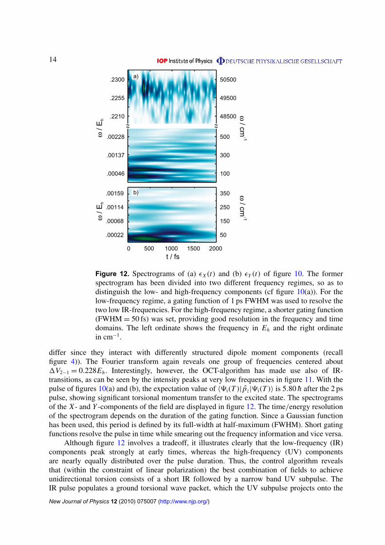
Figure 12. Spectrograms of (a) εX(t) and (b) εY (t) of figure 10. The formerspectrogram has been divided into two different frequency regimes, so as todistinguish the low- and high-frequency components (cf figure 10(a)). For thelow-frequency regime, a gating function of 1 ps FWHM was used to resolve thetwo low IR-frequencies. For the high-frequency regime, a shorter gating function(FWHM = 50 fs) was set, providing good resolution in the frequency and timedomains. The left ordinate shows the frequency in Eh and the right ordinatein cm−1.
differ since they interact with differently structured dipole moment components (recallfigure 4)). The Fourier transform again reveals one group of frequencies centered about1V2−1 = 0.228Eh . Interestingly, however, the OCT-algorithm has made use also of IR-transitions, as can be seen by the intensity peaks at very low frequencies in figure 11. With thepulse of figures 10(a) and (b), the expectation value of 〈9i(T )| pz|9i(T )〉 is 5.80 h after the 2 pspulse, showing significant torsional momentum transfer to the excited state. The spectrogramsof the X - and Y -components of the field are displayed in figure 12. The time/energy resolutionof the spectrogram depends on the duration of the gating function. Since a Gaussian functionhas been used, this period is defined by its full-width at half-maximum (FWHM). Short gatingfunctions resolve the pulse in time while smearing out the frequency information and vice versa.
Although figure 12 involves a tradeoff, it illustrates clearly that the low-frequency (IR)components peak strongly at early times, whereas the high-frequency (UV) componentsare nearly equally distributed over the pulse duration. Thus, the control algorithm revealsthat (within the constraint of linear polarization) the best combination of fields to achieveunidirectional torsion consists of a short IR followed by a narrow band UV subpulse. TheIR pulse populates a ground torsional wave packet, which the UV subpulse projects onto the
New Journal of Physics 12 (2010) 075007 (http://www.njp.org/)

15
excited surface at an opportune instant, when the torsional wave packet has reached the turningpoint and the ground–excited overlap is optimized.
Furthermore, it is seen that the IR pulse duration is under ∼800 fs. Considering thatthe IR frequencies are in the range of 40–200 cm−1, application of equation (4) shows thatthe pulse includes very few optical cycles, just one in the case of the lowest frequency (for40 cm−1Tp ∼ 834 fs) and four in the highest. The optimal control algorithm thus confirms theusefulness of the IR + UV strategy, applied in the previous research to similar problems [47],[66]–[69]. In the next subsection, we ask to what extent and how could the pulse parametersbe set intuitively, bypassing the optimization, to yield the same level of control. In section 3.2we investigate the extent to which unconstrained (polarization shaping) OCT can generate newsolutions, that significantly surpass those of intuitive schemes.
3.1.3. IR + UV strategy. The goal of the IR + UV strategy is to create torsional momentum inthe ground state and then transfer it with an ultrashort (short with respect to torsional motions)pulse to the excited state. We use the same parameters as in the OCT calculations discussed inthe previous subsection but with the target state on the electronic ground state,
9f(T )=
(8f(T )
0
), (20)
where 8f(T ) is a Gaussian wavefunction (equation (17)) having 30.0 h of initial torsionalmomentum, centered about β = π . The field is linearly polarized and hence only the Eµ
y11
component of the dipole contributes to the field–matter interaction. In this case, the overlap9i(t)|9f(t) is not necessarily zero, because both functions belong to the same Hamiltonian,thus no seeding pulse is needed to start the algorithm. A period of 2 ps is simulated and noenvelope function or weighting function is used. Inspecting the convergence behavior of theoverlap, analogous to the discussion of the previous subsection, we find that the algorithm isable to increase the overlap up to ∼87%, with the final wavefunction having a momentumexpectation value of 18.00h. The optimized field is a sinusoidal function, with a central featureof about 52.0 cm−1, as determined through Fourier transform of the final field. This result hasbeen expected: the underlying mechanism is torsional ladder climbing, and in order to excite thesyn-isomer, the pulse needs to be resonant with the level spacing around β = π . These resultsconfirm the conclusion of the previous subsection that, under the conditions of the constraintoptimization considered, the best method to achieve sustained unidirectional torsion in BCH isthe IR + UV strategy.
It remains to discover, however, how sensitive the results are to the parameters of ananalytically constructed pulse. We thus proceed to examine the results of a pulse of the form
Eε(t)= EIR(t) · EεY + EUV(t) · EεX , (21)
where
E j(t)= E0j · sin (ω j t) · s j(t), j = IR,UV, (22)
and s j(t) is an envelope function of duration tp. The parameters of the two pulses are chosen tosatisfy the following conditions:
1. The IR frequency is resonant with the transitions in the syn configuration of the groundstate, so that ladder climbing is facile (cf figure 5(b)), slope of the solid curve).
2. The IR-pulse duration allows only a few half-cycles.
New Journal of Physics 12 (2010) 075007 (http://www.njp.org/)

16
3. E0IR allows sufficient torsional momentum to be gained in the electronic ground state. In
order to maintain comparable fluence while decreasing the pulse duration with respect tothat of the OCT algorithm, we are required to increase the field amplitude.
4. The UV frequency is resonant with 1V2−1 in the vicinity of β = 0.5. The UV-pulse duration is chosen such that the expectation value of the torsional momentum
p1z (t) during the electronic transition remains close to its maximum p1
z max ∼ 19.5h.6. E0
UV is chosen so that population transfer is >95%.
We find that these conditions are satisfied with the IR-laser parameters set to:ωIR = 51.0 cm−1=
0.232 × 10⁻³Eh , E0IR = 4.0 GV m−1, t IR
p = 1485 fs,
sIR(t)=
sin
(π t
t IRp
), 06 t 6 t IR
p ,
0, t > t IRp
(23)
and the UV-laser parameters to: ωUV = 50 000 cm−1= 0.228Eh , E0
UV = 2.5 GV m−1, tUVp =
80 fs
sUV(t)=
sin
(π t
tUVp
), 1675.06 t 6 1675.0 + tUV
p ,
0, t > 1675.0 + tUVp .
(24)
Although we show below that the IR + UV pulse sequence induces the desired motion, thesensitivity to the precise detail of the pulse suggests the advantage of OCT.
Figure 13 summarizes the results obtained with the analytical pulse sequence ofequation (21) (section 3.1.3). The laser pulse is depicted in panel (a). Panel (b) shows theoscillations in the expectation values of the torsional momenta pz(t) for the electronic groundand excited states. While for the former p1
z (t) oscillates around zero (solid curve), in thelatter, once the UV-laser has triggered the electronic transition, p2
z (t) maintains a positive value(dashed curve), undergoing acceleration and deceleration depending on the slope of V2 at thecenter of the wave packet. Panel (c) shows the evolution of the expectation value of the torsionangle, β(t), in the ground (solid) and excited (dashed) states. A full rotation cannot be depictedin this representation, because β spans the 0 → 2π range. A complementary view of the samedynamics in thus provided in panel (d), which shows the probability density |9(t, β)|2 versustime and position.
An alternative way of describing the same driven torsional dynamics is in terms of thetorsional eigenstates, as calculated in the previous section,
C1ν (t)= 〈91(t, β)|81
ν(β)〉 (25)
for the ground and
C2ν (t)= 〈92(t, β)|82
ν(β)〉 (26)
for the excited state, where the β-dependence has been integrated out. The square absolutevalue of these coefficients after turn off of the pulse is shown in figure 14 . Whereas the groundstate is dominated by the lowest few torsional components, the excited state torsional wavepacket is centered about ν = 485 and is broad, involving ∼20 significantly populated states.Clear dominance of the odd components reflects our breaking of the symmetry of the twotorsion senses. The need to determine the pulse parameters to high accuracy, however, limitsthe applicability of the method.
New Journal of Physics 12 (2010) 075007 (http://www.njp.org/)

17
2
0
-2
4 a)
0 1000 2000 3000 4000 0 1000 2000 3000 4000
t / fs t / fs
E/G
Vm
-1
1.0
0.5
-0.1
1.0 π
2.0 π
0.0 π
d)
β/r
ad
1.5 π
1.0 π
0.5 π
c)
<β>
/rad
<β1>
<β2>
200
100
0
b) <p1Z>
<p2Z>
<p Z
>/ h
|Ψ|2
Figure 13. IR + UV strategy. (a) The laser pulse applied. (b) The expectationvalues of the torsional momentum in the ground and excited states. (c) Theexpectation values of the torsional angle in the ground and excited states. (d)The squared absolute value of 9(t, β). After the UV pulse >95% of |9(t, β)|2
is in the excited state. Several cycles of the unidirectional rotation are shown, asthe probability density exits and re-enters the periodic boundaries in the direction2π → 0 at times t ∼ 2 ps and t ∼ 3.1 ps.
0.1
0.3
0.5
0 2 4 6 8
0.02
0.06
0.10
0.14
0.18
470 475 480 485 490 495 500
|C2ν|
2|C1
ν|2
|Cν|2
ν ν
|Cν|2
a) t = 1485.0 fs b) t = 1755 fs
Figure 14. Squared modulus of the projection of 9(t, β) onto its torsionalcomponents in the ground (a) and excited (b) states.
3.2. Polarization shaping
In this section we relax the constraint of linear polarization imposed in section 3.1 and allowthe control algorithm to vary with time the polarization of the field to explore the potentialadvantage of polarization shaping. We remark that polarization shaping has been demonstratedin several experiments [41], [70]–[75].
To gain complementary insight into the controlled torsional dynamics, we perform thecalculations in basis set space, rather than in grid space (see section 2.3). A target operator that
New Journal of Physics 12 (2010) 075007 (http://www.njp.org/)

18
Figure 15. Polarization shaping. (a) The squared modulus of 8(β, t). (b) Theexpectation value of the angular momentum. The polarization-shaped pulse is100 fs long.
embodies the dynamics that we seek to control is a projector onto states with positive angularmomentum,
O target =
nmax∑n>0
|einθ〉〈einθ
|. (27)
In these calculations, we have used a penalty function amplitude of αo = 50 and a penaltyfunction shape of the form described in [76]. This restricts the field strength and ensuresthat the field grows from zero at a finite rate and approaches zero smoothly toward the targettime. Using this method, we are able to restrict ourselves to very short timescales (10–100 fs)while significantly improving our control over the torsional dynamics as compared to the linearpolarization approach.
Figure 15 displays the results. Panel (a) may be compared with figure 13(d) for the IR + UVscheme of section 3.1.3. The probability density exhibits unidirectional motion beginningimmediately after the short pulse and persisting for several cycles before (coherent) dephasingbegins to spread the wave packet. Noteworthy is the difference in the extent of reflection frominteraction with the barriers in figures 15 and 13(d). At the point where the wave packet first
New Journal of Physics 12 (2010) 075007 (http://www.njp.org/)

19
Figure 16. Results of polarization shaping with all dipole/field interactionsincluded. (a) Ground (- - -) and excited (solid) state population along withthe portion of the excited state population above the central barrier at 0.22809Hartrees (solid curve with superimposed circles). (b) Ground (- - -) andexcited (solid) state angular momentum during and immediately after the pulse.(c) X - (left ordinate) and Y - (right ordinate) field components. Note the scaledifference indicating that the Y -component of the field is much more intense.
encounters the excited state torsional barrier at the 0/2π juncture (see figure 4(a)), a faint linecan be seen moving in the direction counter to the bulk of the wave packet, which continuesrotating onward to emerge from the β = 0 side of the coordinate system. This representsportions of the total wave packet that are reflected from the barrier. This happens most noticeablyfor wave packets that have a great deal of population at energies not too far above the peakvalue of the torsional barrier. In figure 15(a), however, such reflection is not observed, since inthe polarization-shaped case the center of the wave packet lies energetically above the highestbound state, as seen in figure 17 and discussed below.
Within the IR + UV scheme, the ground state angular momentum must be built up beforeit can be transferred to the excited state. Within the optimized polarization scheme, the creationof the phase relations necessary for unidirectional rotation and the population of the excitedstate are done simultaneously. Panel (b) displays the excited state angular momentum after thepulse, where it is seen that unidirectional rotation begins immediately after the pulse turnoff.The magnitude of this angular momentum once the wave packet accelerates down the slope ofthe potential approaches 250h, and maintains a large positive value, persisting picoseconds.
Although population transfer occurs steadily through the interaction time with the pulse, itis not until the last 10 fs that the excited state angular momentum begins to change appreciably(figure 16(b)). Thus, the phase information necessary for unidirectionality builds up gradually inthe course of population transitions, but is only triggered in the final sharp sub-pulse near 100 fs.The differences between the dynamics induced by the IR + UV scheme and those induced by thepolarization-shaped pulse are twofold. Firstly, the polarization-shaped pulse is able to increasethe Y -component of the field at the expense of the X -component, thus offsetting the large
New Journal of Physics 12 (2010) 075007 (http://www.njp.org/)

20
Figure 17. The correspondence between the transition strengths 〈811|µ
x12|8
2ν〉 (a)
and the populations of torsional states in the excited electronic state after thepulse (b), (c). Panel (b) corresponds to the IR + UV scheme and panel (c) tothe polarization shaping approach. The shift of the center of the wave packettowards higher energy states is clearly seen. The state numbers here refer to themost highly populated subset of the 73 total excited states. In this representation,state number 46 marks the highest bound state.
difference between the X - and Y-components of the dipole function (see figure 4) that hindersunidirectional rotation. Secondly, the optimal pulse produces a higher energy torsional wavepacket, dominated by states whose energy is above the central torsional barrier (figures 16(a)and 17). This wave packet decohers more slowly than the one due to the IR + UV scheme as itsuffers less from collisions.
Within the IR + UV scheme, there is an anticipated close correspondence between thepopulations in the excited state levels after the pulse sequence and the strengths of theirtransitions from the ground torsional state. Inevitably, the strength of transitions into boundstates is well above that for transitions into states above the barrier, and hence the excitedstate wave packet contains ∼26% of bound states. The short shaped pulse, by contrast, is ableto concentrate the pulse fluence in a short time and thus offset the trend determined by thetransition strengths and place ∼90% of the excited state population in torsional states above the0.22809Eh barrier.
Examination of the control fields involved in the polarization shaping approach shows thatin some respects similar mechanisms apply in this case as in the IR + UV scheme. Figure 18shows the Fourier transforms of the X - and Y -components of the field, illustrating that thefrequency spectrum of the Y -component (red) is reminiscent of that shown in figure 11 forthe linearly polarized field. While both the X- and Y-field components contain frequenciescorresponding to ground-to-ground, excited-to-excited and ground-to-excited transitions, the
New Journal of Physics 12 (2010) 075007 (http://www.njp.org/)

21
0
0.01
0.02
0.03
X-F
ield
Tra
nsfo
rm (
arb
unit
s)
0 0.05 0.1 0.15 0.2 0.25Energy (Hartrees)
0
0.5
1
Y-F
ield
Tra
nsfo
rm (
arb
unit
s)
Figure 18. Frequency domain representation of the X - (black) and Y - (red)components of the field, where the X -component is referred to the right ordinateand the Y -component to the left ordinate. The X -component is considerablyweaker and much broader in frequency space.
Y -component of the polarization-shaped pulse is not nearly as broad in frequency space as theX -component. Both the high- and the low-frequency components of the Y field componentare active throughout the pulse, leading to greater resolution in the frequency domain relativeto the X field component, which is much more concentrated in time and hence broader infrequency domain. Further, one observes a large difference between the peak intensity of themost represented frequency in the Y field component (normalized to 1 for ease of comparison)and that of the X -component (only 0.03). As noted above, this is due to the large differencein strengths of the X - and Y -components of the transition dipole in figure 4(c). The relevantparameter is the interaction strength εX(t)〈81
a|µ|82ν〉, which requires a much lower field strength
to be comparable to εY (t)〈81a|µ|82
ν〉.Complementary insights are provided by the temporal evolution of the fields, provided in
figure 16(c). Here we find that the Y-component of the field is shaped in both the low-frequency(overall envelop) and high-frequency (fine structure) regimes and that its amplitude is highthroughout. The X -component, by contrast, has a very small (although nonzero) amplitude atall but the very early and very late portions of the interaction time, leading to a broadeningin the frequency domain representation. As will be seen below, this does not reduce to asimple two pulse control field, as the small oscillations in the X -component of the field leadto definite polarization when taken in concert with the Y -component of the field. Populationtransfer from the ground to the excited electronic state continues steadily during the pulse, butwith low amplitude oscillations that indicate the creation of coherences. This interpretation isfurther supported by the results of calculations with only one of the field components. Whenonly εX(t) is applied and εY (t) is set to zero, only ∼30% of the population is transferred tothe excited state. When only εY (t) is applied, ∼60% of the population is in the excited state,the results of section 3.1.1 are reproduced, but with no unidirectionality to the excited statewave packet. The wave packet splits into two counter-propagating wave packets, leaving the netangular momentum zero.
Lastly, it is instructive to examine the evolution of the total electric field over time. Here weclearly see the use of multiple elliptical polarizations spanning tens of femtoseconds along withmore exotic forms where the polarization changes rapidly with time. By plotting the changes
New Journal of Physics 12 (2010) 075007 (http://www.njp.org/)

22
a) b) c) d) e)
f) g) h) i) j)
Figure 19. Time evolution of the polarization properties of the optimal field.(a) 10–12 fs, (b) 20–22 fs, (c) 30–32 fs, (d) 40–42 fs, (e) 50–52 fs, (f) 60–62 fs,(g) 70–72 fs, (h) 80–82 fs, (i) 90–92 fs, and (j) 98–100 fs.
in the X and Y control fields simultaneously, we can follow the establishment and change ofparticular pulse polarizations (figure 19). At early times, t ∼ 0–40 fs, the pulse is ellipticallypolarized (panels (a)–(d)) with a slight change of the orientation around 40 fs (panel (d)). Anentirely different behavior, however, is found in the later portions of the pulse, t ∼ 50–90 fs(panels (e)–(i)), where the polarization direction varies rapidly. Finally, the pulse ends with aslowly varying elliptical polarization that decreases in amplitude as the pulse smoothly decaysto zero (panel (j)). Figure 19 thus clarifies the manner in which the polarization-shaped pulsebreaks the rotational symmetry of the system and optimally induces unidirectional torsion.
4. Conclusion
In the preceding sections we explored the extent to which coherent light–matter interactionsalone could drive unidirectional rotation in a symmetric system. We addressed also the moregeneral question if and when can optimal control strategies provide solutions that couldnot be attained by intuitive approaches. Time-dependent approaches based on momentumspace and state space formulations were used in the application of complimentary coherentcontrol techniques, and useful information about wave packet shaping in multiple regimes wasunraveled. As an experimentally relevant model system we used the BCH molecule, a simpleolefin that serves as a prototype of a class of more complicated molecular rotors that share itsessential structural motives. Our conclusions, however, are largely general.
Under constrained polarization conditions, we find that the optimal control algorithmreduces to a simple two-pulse sequence, where a first IR pulse excites a wave packet of torsionalstates and a subsequent UV pulse, timed to an instance where the system is localized at theground state turning point, projects it onto an excited PES. The structure of the excited surfacegives rise to unidirectional motion along the torsional coordinate. We found, however, thatwith the restriction to linear polarization removed, significantly better solutions are unraveled.In particular, an interesting polarization shaping approach is introduced, where ellipticallypolarized light breaks the symmetry between the two senses of torsion.
New Journal of Physics 12 (2010) 075007 (http://www.njp.org/)

23
Acknowledgments
TS is grateful to the National Science Foundation (Award Number CHE-0616927) for support.LG thanks the Deutsche Forschungsgemeinschaft (Project Number GO-1059/2-1) for financialsupport. Additionally, B Schmidt is gratefully acknowledged for providing the authors with theQMBOUND software.
References
[1] Feringa B L (ed) 2001 Molecular Switches (Weinheim: Wiley-VCH)[2] Iwamura H and Mislow K 1988 Acc. Chem. Res. 21 175[3] Jiménez M C, Dietrich-Buchecker C and Sauvage J-P 2000 Angew. Chem., Int. Ed. Engl. 39 3284[4] Koga N, Kawada Y and Iwamura H 1983 J. Am. Chem. Soc. 105 5498[5] Badjic J D, Balzani V, Credi A, Silvi S and Stoddart J F 2004 Science 303 1845[6] Koumura N, Zijlstra R W J, van Delden R A, Harada N and Feringa B L 1999 Nature 401 152[7] Balazani V, Credi A and Venturi M 2008 Molecular Devices and Machines—Concepts and Perspectives for
the Nanoworld (Weinheim: Wiley-VCH)[8] Bottari G, Dehez F, Leigh D A, Nash P J, Pérez E M, Wong J K Y and Zerbetto F 2003 Angew. Chem., Int.
Ed. Engl. 42 5886[9] Garaudée S, Silvi S, Venturi M, Credi A, Flood A H and Stoddart J F 2005 ChemPhysChem 6 2145
[10] Tseng H, Vignon S A and Stoddart J F 2003 Angew. Chem., Int. Ed. Engl. 42 1491[11] Kottas G S, Clarke L I, Horinek D and Michl J 2005 Chem. Rev. 105 1281[12] Kay E R, Leigh D A and Zerbetto F 2007 Angew. Chem., Int. Ed. Engl. 46 72[13] Kolomeisky A B and Fisher M E 2007 Ann. Rev. Phys. Chem. 58 675[14] Seideman T 2003 J. Mod. Opt 50 2393[15] Král P and Seideman T 2005 J. Chem. Phys. 123 184702[16] Kaun C-C and Seideman T 2005 Phys. Rev. Lett. 94 226801[17] Jorn R and Seideman T 2006 J. Chem. Phys. 124 084703[18] Jorn R, Livshits E, Baer R and Seideman T 2007 Isr. J. Chem. 47 99[19] Rabitz H A, Hsieh M M and Rosenthal C M 2004 Science 303 1998[20] Shapiro M and Brumer P 2003 Principals of Quantum Control of Molecular Processes (New York: Wiley)[21] Brixner T and Gerber G 2003 ChemPhysChem 4 418[22] Vitanov N V, Halfmann T, Shore B W and Bergmann K 2001 Ann. Rev. Phys. Chem. 52 763[23] Vitanov N V, Fleischhauer M, Shore B W and Bergmann K 2001 Adv. At. Mol. Opt. Phys. 46 55[24] Rice S and Zhao M 2000 Optical Control of Molecular Dynamics (New York: Wiley)[25] Rabitz H, de Vivie-Riedle R, Motzkus M and Kompa K 2000 Science 288 82[26] Gordon R J and Rice S A 1997 Ann. Rev. Phys. Chem. 48 601[27] Brumer P and Shapiro M 1992 Ann. Rev. Phys. Chem. 43 257[28] de Vivie-Riedle R, Rabitz H and Kompa K L (ed) 2001 Chem. Phys., Special Issue on Laser Control of
Quantum Dynamics vol 267 (Amsterdam: Elsevier)[29] Huang G M, Tarn T J and Clark J W 1983 J. Math. Phys. 24 2608[30] Rabitz H, Peirce A P and Dahleh M A 1988 Phys. Rev. A 37 4950[31] Assion A, Baumert T, Bergt M, Brixner T, Kiefer B, Seyfried V, Strehle M and Gerber G 1998 Science
282 919[32] Glaß A, Rozgonyi T, Feurer T, Sauerbrey R and Szabó G 2000 Appl. Phys. B 71 267[33] Bartels R, Backus S, Zeek E, Misoguti L, Vdovin G, Christov I P, Murnane M M and Kapteyn H C 2000
Nature 406 164[34] Brixner T, Damrauer N H and Gerber G 2001 Adv. Mol. Opt. Phys. 46 1[35] Levis R J, Menkir G M and Rabitz H 2001 Science 292 709
New Journal of Physics 12 (2010) 075007 (http://www.njp.org/)

24
[36] Herek J L, Wohlleben W, Cogdell R J, Zeidler D and Motzkus M 2002 Nature 417 533[37] Hornung T, Motzkus M and de Vivie-Riedle R 2002 Phys. Rev. A 65 021403[38] Daniel C, Full J, González L, Lupulescu C, Manz J, Merli A, Vajda S and Wöste L 2003 Science 299 536[39] Kurtz L, Rabitz H and de Vivie-Riedle R 2002 Phys. Rev. A 65 032514[40] Cardoza D, Baertschy M and Weinacht T C 2005 J. Chem. Phys. 123 074315[41] Wollenhaupt M, Krug M, Köhler J, Bayer T, Sarpe-Tudoran C and Baumert T 2009 Appl. Phys. B 95 245[42] Balzani V, Credi A and Venturi M 2009 Chem. Soc. Rev. 38 1542[43] Browne W R and Feringa B L 2009 Ann. Rev. Phys. Chem. 60 407[44] Hoki K, Yamaki M, Koseki S and Fujimura Y 2003 J. Chem. Phys. 118 497[45] Hoki K, Yamaki M, Koseki S and Fujimura Y 2003 J. Chem. Phys. 119 12393[46] Yamaki M, Hoki K, Kono H and Fujimura Y 2008 Chem. Phys. 347 272[47] Fujimura Y, González L, Kröner D, Manz J, Mehdaoui I and Schmidt B 2004 Chem. Phys. Lett. 386 248[48] Koumura N, Geertsema E M, van Gelder M B, Meetsma A and Feringa B L 2002 J. Am. Chem. Soc.
124 5037[49] van Delden R A, ter Wiel M K J, Pollard M M, Vicario J, Koumura N and Feringa B L 2005 Nature 437 1337[50] Pollard M M, Lubomska M, Rudolf P and Feringa B L 2007 Angew. Chem., Int. Ed. Engl. 46 1278[51] Snyder P A and Clark L B 1970 J. Phys. Chem. 52 998[52] Allan M, Snyder P A and Robin M B 1985 J. Phys. Chem. 89 4900[53] Snyder P A, Hansen R W C and Rowe E M 1996 J. Phys. Chem. 100 17756[54] Rijkenberg R A, Buma W J, van Walree C A and Jenneskens L W 2002 J. Phys. Chem. A 106 5249[55] Hoogesteger F J, van Lenthe J H and Jenneskens L W 1996 Chem. Phys. Lett. 259 178[56] Havenith R W A, van Lenthe J H, Jenneskens L W and Hoogesteger F J 1997 Chem. Phys. 225 139[57] Havenith R W A, Jenneskens L W and van Lenthe J H 1998 Chem. Phys. Lett. 282 39[58] Havenith R W A, van Dam H J J and van Lenthe J H 1999 Chem. Phys. 246 49[59] Rijkenberg R A, Buma W J, van Lenthe J H, Jenneskens L W and Schmal L P 2003 ChemPhysChem 4 97[60] Pérez-Hernández G, González L and Serrano-Andrés L 2008 ChemPhysChem 9 2544[61] Robin M B 1985 Higher Excited States of Polyatomic Molecules vol III (New York: Academic)[62] Frisch M J et al 2004 Gaussian 03, Revision C.02 (Wallingford, CT: Gaussian, Inc.)[63] Feit M D, Fleck J Jr and Steiger A 1982 J. Comput. Phys. 47 412[64] Feit M D and Fleck J Jr 1983 J. Chem. Phys. 78 301[65] Zhu W, Botina J and Rabitz H 1997 J. Chem. Phys. 108 1953[66] Elghobashi N, Krause P, Manz J and Oppel M 2003 Phys. Chem. Chem. Phys. 5 4806[67] Elghobashi N, González L and Manz J 2004 J. Chem. Phys. 120 8002[68] Elghobashi N and González L 2004 Phys. Chem. Chem. Phys. 6 4071[69] Rozgonyi T and González L 2008 Chem. Phys. Lett. 459 39[70] Brixner T 2003 Appl. Phys. B 76 531[71] Brixner T, Krampert G, Niklaus P and Gerber G 2002 Appl. Phys. B 74 S133[72] Brixner T, Damrauer N H, Krampert G, Niklaus P and Gerber G 2003 J. Opt. Soc. Am. B 20 878[73] Brixner T and Gerber G 2001 Opt. Lett. 26 557[74] Golan B, Fradkin Z, Kopnov G, Oron D and Naaman R 2009 J. Chem. Phys. 130 064705[75] Weber S M, Plewicki M, Weise F and Lindigner A 2008 J. Chem. Phys. 128 174306[76] Atabek O, Dion C and Haj-Yedder A 2003 J. Phys. B: At. Mol. Opt. Phys. 36 4667
New Journal of Physics 12 (2010) 075007 (http://www.njp.org/)