Bioinspired micro-composite structure - Roberto...
8
Bioinspired micro-composite structure L. Chen and R. Ballarini a) Department of Civil Engineering, Case Western Reserve University, Cleveland, Ohio 44106-7201 H. Kahn and A.H. Heuer Department of Materials Science and Engineering, Case Western Reserve University, Cleveland, Ohio 44106 (Received 4 May 2006; accepted 13 September 2006) This paper presents the design, fabrication, and mechanical testing of a bioinspired composite structure with characteristic dimensions on the order of tens of microns. The microarchitecture, designed and fabricated using microelectromechanical systems (MEMS) technology, involves two distinct length scales and represents the first attempt at mimicking the crossed-lamellar microstructure of molluscan shells such as the giant Queen conch, Strombus gigas, which contains features with dimensions spanning five distinct length scales. The displacement control capabilities of a nanoindenter enabled the observation of the graceful failure of the micro-composite under three point bending and, in turn, the measurement of its post-peak load–displacement response and work of fracture. I. INTRODUCTION Studies performed on natural brittle materials suggest a pervasive theme, namely that nature makes structures, not materials, and that these structures are often lami- nated. The structures created by organisms, although made from rather mundane materials, show impressive properties, which furthermore are very well suited for the intended function (structure/function/performance corre- lations have been assumed due to natural selection). The diversity of microstructure in molluscan shells testifies to the flexibility of this approach. It would be desirable if materials scientists developed techniques to produce structures, as opposed to materials, and undertook such developments in collaboration with mechanical design- ers. Study and careful analysis of naturally occurring composites—an aspect of the so-called biomimetic or bioinspired approach—can provide much insight for the design of new, improved materials, particularly compos- ites composed of a large volume fraction of a brittle constituent. Laminated structures composed of mostly brittle constituents offer promise in a wide range of ap- plications, including hot section components in aircraft engines, pavement material for airfields and roads, and electronic packaging. Exploration of the mechanical behavior of a diverse ar- ray of microstructural designs through fabrication and me- chanical testing is economically prohibitive. Therefore, the development of bioinspired structural designs will undoubtedly rely on multiscale computational tools whose predictions will be assessed through limited num- bers of carefully designed experiments. Microelectro- mechanical systems (MEMS) technology offers promise for prototyping structural designs of laminated compos- ites and can provide data to assess the predictive capa- bilities of the computational models because it enables economical fabrication of very large numbers of speci- mens on a single chip; testing using commercially avail- able nanoindenters and probe stations is then straightfor- ward. For the micro-composite described in this paper, as many as 576 specimens were fabricated on each chip. The inspiration for the micro-composite structure de- scribed in this paper comes from previous studies of the microarchitecture of molluscan shells, 1–3 which are ex- quisitely designed biocomposites (biological ceramics) consisting of calcitic or aragonitic CaCO 3 and a small quantity of organic components (the non-mineral portion of mineralized tissue is referred to as the matrix in bio- logical jargon). They are common examples of very heavily mineralized hard tissue, the organic components comprising as little as 1% of the shell volume. Compared with engineered ceramics or nonbiogenic (mineral) cal- cium carbonate, mollusk shells exhibit an extraordinary work of fracture, several orders of magnitude higher than ceramists have been able to achieve in ceramic–matrix composites. Such impressive properties originate from the microstructural design possible by biological fabri- cation, essentially the organization of the biominerals and the protein matrix. a) Address all correspondence to this author. Present address: Department of Civil Engineering, University of Minnesota, Minneapolis, Minnesota 55455. e-mail: [email protected] DOI: 10.1557/JMR.2007.0016 J. Mater. Res., Vol. 22, No. 1, Jan 2007 © 2007 Materials Research Society 124
Transcript of Bioinspired micro-composite structure - Roberto...
Bioinspired micro-composite structure
L. Chen and R. Ballarinia)
Department of Civil Engineering, Case Western Reserve University, Cleveland, Ohio 44106-7201
H. Kahn and A.H. HeuerDepartment of Materials Science and Engineering, Case Western Reserve University,Cleveland, Ohio 44106
(Received 4 May 2006; accepted 13 September 2006)
This paper presents the design, fabrication, and mechanical testing of a bioinspiredcomposite structure with characteristic dimensions on the order of tens of microns.The microarchitecture, designed and fabricated using microelectromechanical systems(MEMS) technology, involves two distinct length scales and represents the firstattempt at mimicking the crossed-lamellar microstructure of molluscan shells such asthe giant Queen conch, Strombus gigas, which contains features with dimensionsspanning five distinct length scales. The displacement control capabilities of ananoindenter enabled the observation of the graceful failure of the micro-compositeunder three point bending and, in turn, the measurement of its post-peakload–displacement response and work of fracture.
I. INTRODUCTION
Studies performed on natural brittle materials suggesta pervasive theme, namely that nature makes structures,not materials, and that these structures are often lami-nated. The structures created by organisms, althoughmade from rather mundane materials, show impressiveproperties, which furthermore are very well suited for theintended function (structure/function/performance corre-lations have been assumed due to natural selection). Thediversity of microstructure in molluscan shells testifies tothe flexibility of this approach. It would be desirable ifmaterials scientists developed techniques to producestructures, as opposed to materials, and undertook suchdevelopments in collaboration with mechanical design-ers. Study and careful analysis of naturally occurringcomposites—an aspect of the so-called biomimetic orbioinspired approach—can provide much insight for thedesign of new, improved materials, particularly compos-ites composed of a large volume fraction of a brittleconstituent. Laminated structures composed of mostlybrittle constituents offer promise in a wide range of ap-plications, including hot section components in aircraftengines, pavement material for airfields and roads, andelectronic packaging.
Exploration of the mechanical behavior of a diverse ar-
ray of microstructural designs through fabrication and me-chanical testing is economically prohibitive. Therefore,the development of bioinspired structural designs willundoubtedly rely on multiscale computational toolswhose predictions will be assessed through limited num-bers of carefully designed experiments. Microelectro-mechanical systems (MEMS) technology offers promisefor prototyping structural designs of laminated compos-ites and can provide data to assess the predictive capa-bilities of the computational models because it enableseconomical fabrication of very large numbers of speci-mens on a single chip; testing using commercially avail-able nanoindenters and probe stations is then straightfor-ward. For the micro-composite described in this paper, asmany as 576 specimens were fabricated on each chip.
The inspiration for the micro-composite structure de-scribed in this paper comes from previous studies of themicroarchitecture of molluscan shells,1–3 which are ex-quisitely designed biocomposites (biological ceramics)consisting of calcitic or aragonitic CaCO3 and a smallquantity of organic components (the non-mineral portionof mineralized tissue is referred to as the matrix in bio-logical jargon). They are common examples of veryheavily mineralized hard tissue, the organic componentscomprising as little as 1% of the shell volume. Comparedwith engineered ceramics or nonbiogenic (mineral) cal-cium carbonate, mollusk shells exhibit an extraordinarywork of fracture, several orders of magnitude higher thanceramists have been able to achieve in ceramic–matrixcomposites. Such impressive properties originate fromthe microstructural design possible by biological fabri-cation, essentially the organization of the biomineralsand the protein matrix.
a)Address all correspondence to this author.Present address: Department of Civil Engineering, University ofMinnesota, Minneapolis, Minnesota 55455.e-mail: [email protected]
DOI: 10.1557/JMR.2007.0016
J. Mater. Res., Vol. 22, No. 1, Jan 2007 © 2007 Materials Research Society124
From the morphology and organization of the bio-minerals, five common shell microarchitectures can berecognized in molluscan shells: the crossed-lamellar, na-creous, prismatic, foliated, and homogeneous microar-chitectures.4 The common characteristic of shell micro-structures is that the building blocks are very small, withlengths of tens of nanometers to microns, and are orga-nized in an ordered arrangement in at least one dimen-sion.5 The organic matrix is present as a thin envelope orsheet surrounding each mineral unit.5 The mechanicalproperties of shells with different structures vary consid-erably.2,6
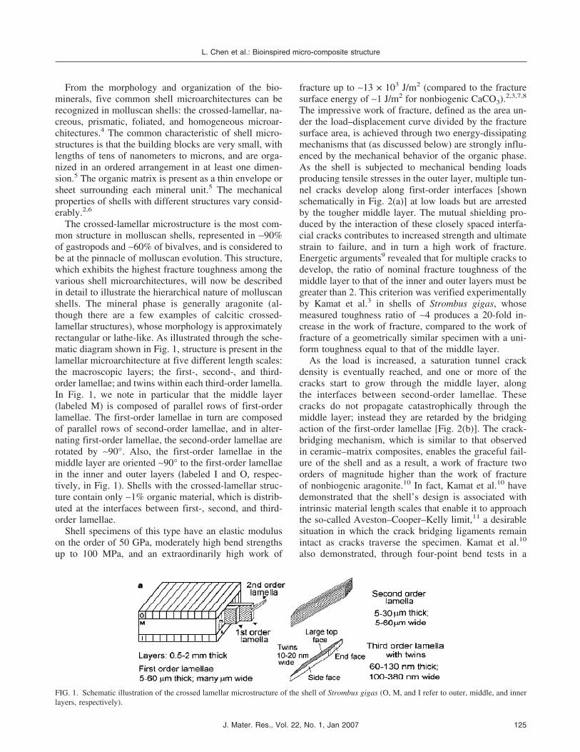
The crossed-lamellar microstructure is the most com-mon structure in molluscan shells, represented in ∼90%of gastropods and ∼60% of bivalves, and is considered tobe at the pinnacle of molluscan evolution. This structure,which exhibits the highest fracture toughness among thevarious shell microarchitectures, will now be describedin detail to illustrate the hierarchical nature of molluscanshells. The mineral phase is generally aragonite (al-though there are a few examples of calcitic crossed-lamellar structures), whose morphology is approximatelyrectangular or lathe-like. As illustrated through the sche-matic diagram shown in Fig. 1, structure is present in thelamellar microarchitecture at five different length scales:the macroscopic layers; the first-, second-, and third-order lamellae; and twins within each third-order lamella.In Fig. 1, we note in particular that the middle layer(labeled M) is composed of parallel rows of first-orderlamellae. The first-order lamellae in turn are composedof parallel rows of second-order lamellae, and in alter-nating first-order lamellae, the second-order lamellae arerotated by ∼90°. Also, the first-order lamellae in themiddle layer are oriented ∼90° to the first-order lamellaein the inner and outer layers (labeled I and O, respec-tively, in Fig. 1). Shells with the crossed-lamellar struc-ture contain only ∼1% organic material, which is distrib-uted at the interfaces between first-, second, and third-order lamellae.
Shell specimens of this type have an elastic moduluson the order of 50 GPa, moderately high bend strengthsup to 100 MPa, and an extraordinarily high work of
fracture up to ∼13 × 103 J/m2 (compared to the fracturesurface energy of ∼1 J/m2 for nonbiogenic CaCO3).2,3,7,8
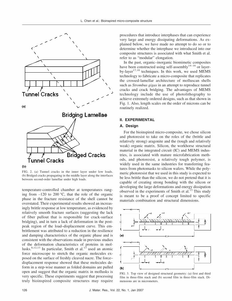
The impressive work of fracture, defined as the area un-der the load–displacement curve divided by the fracturesurface area, is achieved through two energy-dissipatingmechanisms that (as discussed below) are strongly influ-enced by the mechanical behavior of the organic phase.As the shell is subjected to mechanical bending loadsproducing tensile stresses in the outer layer, multiple tun-nel cracks develop along first-order interfaces [shownschematically in Fig. 2(a)] at low loads but are arrestedby the tougher middle layer. The mutual shielding pro-duced by the interaction of these closely spaced interfa-cial cracks contributes to increased strength and ultimatestrain to failure, and in turn a high work of fracture.Energetic arguments9 revealed that for multiple cracks todevelop, the ratio of nominal fracture toughness of themiddle layer to that of the inner and outer layers must begreater than 2. This criterion was verified experimentallyby Kamat et al.3 in shells of Strombus gigas, whosemeasured toughness ratio of ∼4 produces a 20-fold in-crease in the work of fracture, compared to the work offracture of a geometrically similar specimen with a uni-form toughness equal to that of the middle layer.
As the load is increased, a saturation tunnel crackdensity is eventually reached, and one or more of thecracks start to grow through the middle layer, alongthe interfaces between second-order lamellae. Thesecracks do not propagate catastrophically through themiddle layer; instead they are retarded by the bridgingaction of the first-order lamellae [Fig. 2(b)]. The crack-bridging mechanism, which is similar to that observedin ceramic–matrix composites, enables the graceful fail-ure of the shell and as a result, a work of fracture twoorders of magnitude higher than the work of fractureof nonbiogenic aragonite.10 In fact, Kamat et al.10 havedemonstrated that the shell’s design is associated withintrinsic material length scales that enable it to approachthe so-called Aveston–Cooper–Kelly limit,11 a desirablesituation in which the crack bridging ligaments remainintact as cracks traverse the specimen. Kamat et al.10
also demonstrated, through four-point bend tests in a
FIG. 1. Schematic illustration of the crossed lamellar microstructure of the shell of Strombus gigas (O, M, and I refer to outer, middle, and innerlayers, respectively).
L. Chen et al.: Bioinspired micro-composite structure
J. Mater. Res., Vol. 22, No. 1, Jan 2007 125
temperature-controlled chamber at temperatures rang-ing from –120 to 200 °C, that the role of the organicphase in the fracture resistance of the shell cannot beoverstated. Their experimental results showed an increas-ingly brittle response at low temperature, as evidenced byrelatively smooth fracture surfaces (suggesting the lackof fiber pullout that is responsible for crack-surfacebridging), and in turn a lack of deformation in the post-peak region of the load–displacement curve. This em-brittlement was attributed to a reduction in the resilienceand damping characteristics of the organic phase and isconsistent with the observations made in previous studiesof the deformation characteristics of proteins in mol-lusks.8,12,13 In particular, Smith et al.13 used an atomicforce microscope to stretch the organic molecules ex-posed on the surface of freshly cleaved nacre. The force–displacement response showed that these molecules de-form in a step-wise manner as folded domains are pulledopen and suggest that the organic matrix in mollusks isvery specific. These experiments suggest that processingtruly bioinspired composite structures may require
procedures that introduce interphases that can experiencevery large and energy dissipating deformations. As ex-plained below, we have made no attempt to do so or todetermine whether the interphase we introduced into ourcomposite structures is associated with what Smith et al.refer to as “modular” elongation.
In the past, organic–inorganic biomimetic compositeshave been constructed using self-assembly14–16 or layer-by-layer17,18 techniques. In this work, we used MEMStechnology to fabricate a micro-composite that replicatesthe crossed-lamellar architecture of molluscan shellssuch as Strombus gigas in an attempt to reproduce tunnelcracks and crack bridging. The advantages of MEMStechnology include the use of photolithography toachieve extremely ordered designs, such as that shown inFig. 1. Also, length scales on the order of microns can beroutinely realized.
II. EXPERIMENTAL
A. Design
For the bioinspired micro-composite, we chose siliconand photoresist to take on the roles of the (brittle andrelatively strong) aragonite and the (tough and relativelyweak) organic matrix. Silicon, the workhorse structuralmaterial in the integrated circuit (IC) and MEMS indus-tries, is associated with mature microfabrication meth-ods, and photoresist, a relatively tough polymer, iswidely used in the same industries for transferring fea-tures from photomasks to silicon wafers. While the poly-meric photoresist that we used in this study is expected tobe less brittle than the silicon, we do not pretend that it iscapable of creating strong bonding with the silicon ordeveloping the large deformations and energy dissipationobserved in the experiments of Smith et al.13 This studyis meant to be a proof of concept limited to specificmaterials combination and structural dimensions.
FIG. 2. (a) Tunnel cracks in the inner layer under low loads.(b) Bridged cracks propagating in the middle layer along the interfacesbetween second-order lamellae under high loads.
FIG. 3. Top view of designed structural geometry: (a) first and thirdfilm in three-film stack and (b) second film in three-film stack. Di-mensions are in micrometers.
L. Chen et al.: Bioinspired micro-composite structure
J. Mater. Res., Vol. 22, No. 1, Jan 2007126
The laminated micro-composite is a doubly clampedbeam that consists of a stack of three consecutively de-posited films, two of which are shown schematically inFig. 3. The architecture of each film is a two-length scaleapproximation of the inner (or equivalently outer) andmiddle layers of the shell of Strombus gigas. The innerlayer (the bottom half of the beams sketched in Fig. 3)contains vertical interfaces whose role is to crack at rela-tively low loads, while the middle layer (the top halfof the beams sketched in Fig. 3) contains interfaces ori-ented at either +45° or −45° with respect to the horizon-tal. The films are stacked with an alternating arrange-ment of the angled interfaces, so that in principle, themiddle layer should be tough enough to arrest the tunnelcracks that develop in the inner layer. We have not yet
fabricated structures with a larger number of layers andtherefore do not know how sensitive the mechanical be-havior is to the number of layers. We do note, however,that Kamat et al.’s study suggests that it is the threedimensional gradation of properties that enables biologi-cal structures to achieve superior mechanical perfor-mance.
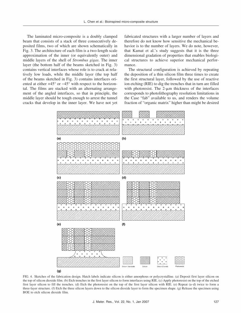
The structural configuration is achieved by repeatingthe deposition of a thin silicon film three times to createthe first structural layer, followed by the use of reactiveion etching (RIE) to dig the trenches that in turn are filledwith photoresist. The 2-�m thickness of the interfacescorresponds to photolithography resolution limitations inthe Case “fab” available to us, and renders the volumefraction of “organic matrix” higher than might be desired
FIG. 4. Sketches of the fabrication design. Hatch labels indicate silicon is either amorphous or polycrystalline. (a) Deposit first layer silicon onthe top of silicon dioxide film. (b) Etch trenches in the first layer silicon to form interfaces using RIE. (c) Apply photoresist on the top of the etchedfirst layer silicon to fill the trenches. (d) Etch the photoresist on the top of the first layer silicon with RIE. (e) Repeat (a–d) twice to form athree-layer structure. (f) Etch the three silicon layers down to the silicon dioxide layer to form the specimen shape. (g) Release the specimen usingBOE to etch silicon dioxide film.
L. Chen et al.: Bioinspired micro-composite structure
J. Mater. Res., Vol. 22, No. 1, Jan 2007 127
for structural optimization. The fabrication sequence isshown in Fig. 4 and is discussed in the next section.
B. Fabrication
Two steps are critical for producing a structurallysound micro-composite: trench etching of the silicon lay-ers and filling of the trenches with photoresist. The fab-rication recipe is summarized next. More details can befound elsewhere.19
One-hundred-millimeter-diameter, 500-�m-thick sili-con wafers were used. First, a 2-�m-thick silicon dioxidelayer was thermally grown. After oxidation, a 2.5-�m-thick polysilicon film was deposited via low-pressurechemical-vapor deposition at 617 °C using SiH4 gas witha deposition rate of 9.5 nm/min [Fig. 4(a)]. This poly-crystalline film is associated with high compressivestress and was therefore annealed for 1 h at 1100 °C toreduce these residual stresses.
Standard photolithography was used to define thetrenches in the first polysilicon layer using a LAM490tool (Lam Research Corp., Fremont, CA), as shown inFig. 4(b). Shipley 1813 photoresist (Phoenix, AZ) wasspun on to fill in the trenches [Fig. 4(c)], and the photo-resist left on top of the silicon film was removed[Fig. 4(d)]. The three-layer structure was achieved byrepeating this procedure two more times [Fig. 4(e)] withslightly thinner sputtered silicon films (2.1 �m for thesecond film and 2.2 �m for the third film). A relativelythin layer of photoresist remained on the surface of thestructure, as complete removal could potentially have ledto damage to the third silicon film.
The 6.8-�m-thick structure was then etched using RIEto form the final structure [Fig. 4(f)]. After the finaletching step, the wafer was dipped in a buffered oxide
etch (BOE) solution containing HF for 155 min to com-pletely release the devices [Fig. 4(g)]. Figure 5 shows asuccessfully released device.
C. Measuring the mechanical properties ofthe micro-composite
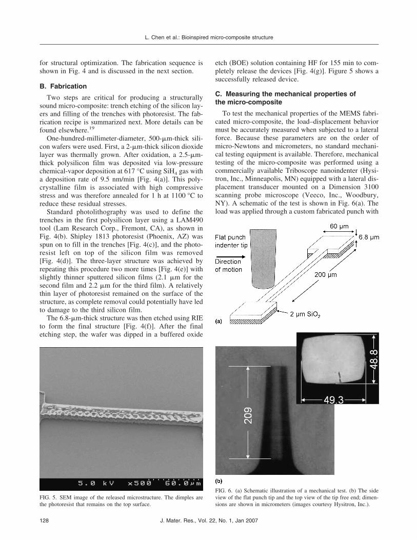
To test the mechanical properties of the MEMS fabri-cated micro-composite, the load–displacement behaviormust be accurately measured when subjected to a lateralforce. Because these parameters are on the order ofmicro-Newtons and micrometers, no standard mechani-cal testing equipment is available. Therefore, mechanicaltesting of the micro-composite was performed using acommercially available Triboscope nanoindenter (Hysi-tron, Inc., Minneapolis, MN) equipped with a lateral dis-placement transducer mounted on a Dimension 3100scanning probe microscope (Veeco, Inc., Woodbury,NY). A schematic of the test is shown in Fig. 6(a). Theload was applied through a custom fabricated punch with
FIG. 5. SEM image of the released microstructure. The dimples arethe photoresist that remains on the top surface.
FIG. 6. (a) Schematic illustration of a mechanical test. (b) The sideview of the flat punch tip and the top view of the tip free end; dimen-sions are shown in micrometers (images courtesy Hysitron, Inc.).
L. Chen et al.: Bioinspired micro-composite structure
J. Mater. Res., Vol. 22, No. 1, Jan 2007128
a flat tip whose side and cross-sectional views are shownin Fig. 6(b). The flat surface of the tip enabled matedcontact with the substrate and mitigated the riding of thepunch over the thin specimen. Specific data points in theload–displacement curve could not be associated withdamage events because of the lack of an in situ high-magnification visual system to observe deformation his-tory during loading.
The lateral (in-plane) test was conducted using dis-placement control at a stroke rate of 22 �m/min. Nonormal force was applied, and the vertical displacementand force were constantly monitored to ensure that theindenter tip did not ride over the specimens. The maindisadvantage of the nanoindenter with the lateral forcetransducer was that the maximum stroke was limited to10 �m. This proved to be insufficient to completely
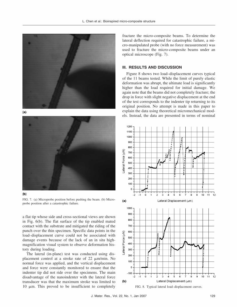
fracture the micro-composite beams. To determine thelateral deflection required for catastrophic failure, a mi-cro-manipulated probe (with no force measurement) wasused to fracture the micro-composite beams under anoptical microscope (Fig. 7).
III. RESULTS AND DISCUSSION
Figure 8 shows two load–displacement curves typicalof the 11 beams tested. While the limit of purely elasticdeformation was abrupt, the ultimate load is significantlyhigher than the load required for initial damage. Weagain note that the beams did not completely fracture; thedrop in force with slight negative displacement at the endof the test corresponds to the indenter tip returning to itsoriginal position. No attempt is made in this paper toexplain the data using theoretical micromechanical mod-els. Instead, the data are presented in terms of nominal
FIG. 7. (a) Microprobe position before pushing the beam. (b) Micro-probe position after a catastrophic failure.
FIG. 8. Typical lateral load–displacement curves.
L. Chen et al.: Bioinspired micro-composite structure
J. Mater. Res., Vol. 22, No. 1, Jan 2007 129
strength and dissipated energy. The 11 tests produced anaverage nominal yield stress of 11.4 MPa with a standarddeviation of 3.1 MPa and an average ultimate strength of26.3 MPa with a standard deviation of 4.2 MPa. Thesevalues correspond to those of a homogeneous doublyclamped elastic beam subjected to a point load with noaxial forces, whose maximum stress is thus given as
� =Md
I=
PLd
8I, (1)
where P is the applied (concentrated) load, L is the spanof the beam, d is the half beam width, and I is its momentof inertia. For the micro-composite, the total beam thick-ness was measured using a Dektak profilometer (VeecoInstruments, Woodbury, NY), and the width was meas-ured in the scanning electron microscope (SEM). Theultimate strength is approximately one fourth that of theshell of Strombus gigas.
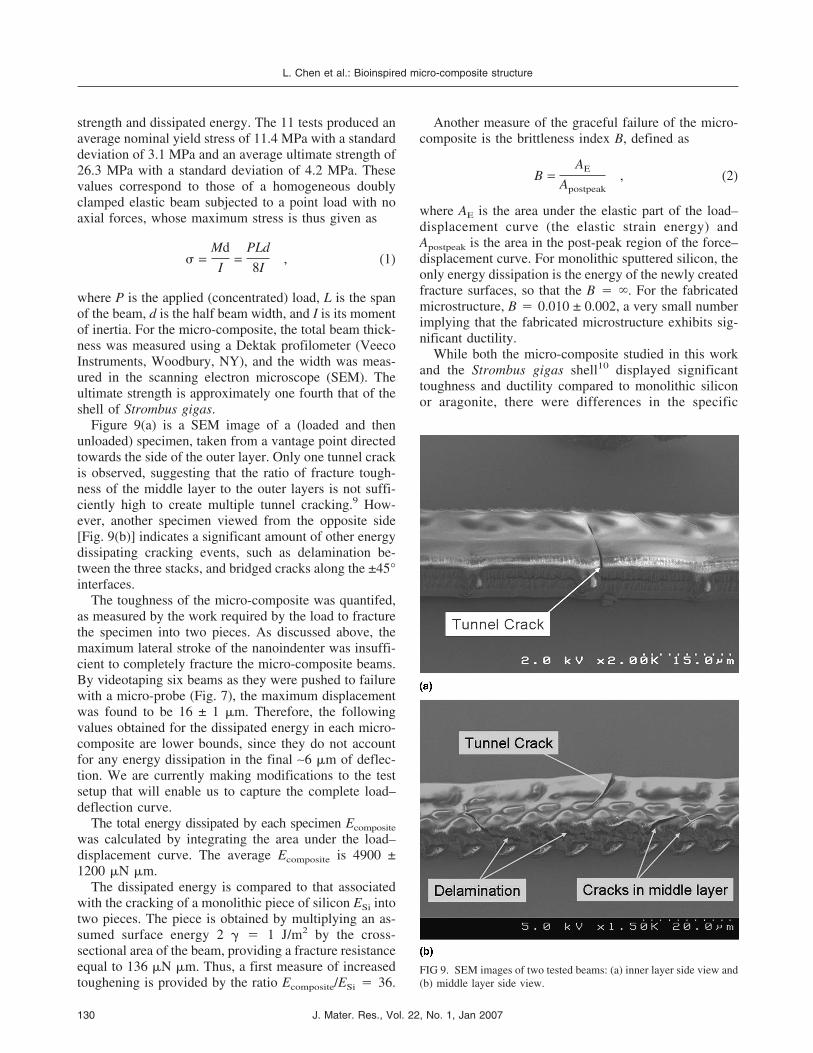
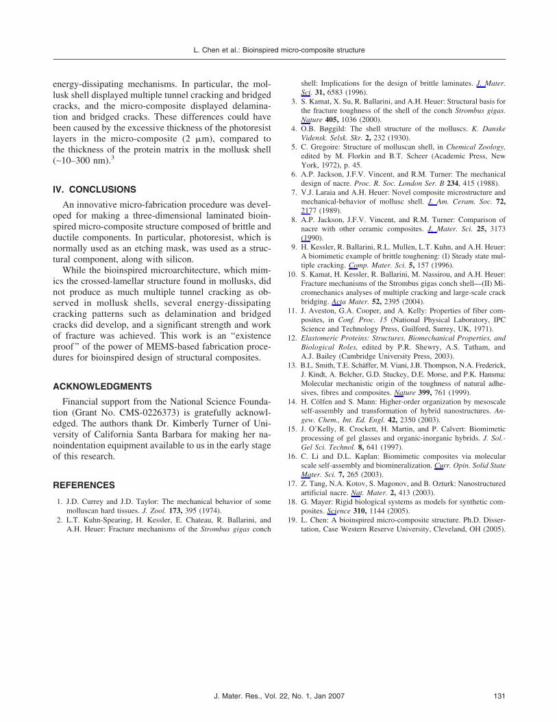
Figure 9(a) is a SEM image of a (loaded and thenunloaded) specimen, taken from a vantage point directedtowards the side of the outer layer. Only one tunnel crackis observed, suggesting that the ratio of fracture tough-ness of the middle layer to the outer layers is not suffi-ciently high to create multiple tunnel cracking.9 How-ever, another specimen viewed from the opposite side[Fig. 9(b)] indicates a significant amount of other energydissipating cracking events, such as delamination be-tween the three stacks, and bridged cracks along the ±45°interfaces.
The toughness of the micro-composite was quantifed,as measured by the work required by the load to fracturethe specimen into two pieces. As discussed above, themaximum lateral stroke of the nanoindenter was insuffi-cient to completely fracture the micro-composite beams.By videotaping six beams as they were pushed to failurewith a micro-probe (Fig. 7), the maximum displacementwas found to be 16 ± 1 �m. Therefore, the followingvalues obtained for the dissipated energy in each micro-composite are lower bounds, since they do not accountfor any energy dissipation in the final ∼6 �m of deflec-tion. We are currently making modifications to the testsetup that will enable us to capture the complete load–deflection curve.
The total energy dissipated by each specimen Ecomposite
was calculated by integrating the area under the load–displacement curve. The average Ecomposite is 4900 ±1200 �N �m.
The dissipated energy is compared to that associatedwith the cracking of a monolithic piece of silicon ESi intotwo pieces. The piece is obtained by multiplying an as-sumed surface energy 2 � � 1 J/m2 by the cross-sectional area of the beam, providing a fracture resistanceequal to 136 �N �m. Thus, a first measure of increasedtoughening is provided by the ratio Ecomposite/ESi � 36.
Another measure of the graceful failure of the micro-composite is the brittleness index B, defined as
B =AE
Apostpeak, (2)
where AE is the area under the elastic part of the load–displacement curve (the elastic strain energy) andApostpeak is the area in the post-peak region of the force–displacement curve. For monolithic sputtered silicon, theonly energy dissipation is the energy of the newly createdfracture surfaces, so that the B � �. For the fabricatedmicrostructure, B � 0.010 ± 0.002, a very small numberimplying that the fabricated microstructure exhibits sig-nificant ductility.
While both the micro-composite studied in this workand the Strombus gigas shell10 displayed significanttoughness and ductility compared to monolithic siliconor aragonite, there were differences in the specific
FIG 9. SEM images of two tested beams: (a) inner layer side view and(b) middle layer side view.
L. Chen et al.: Bioinspired micro-composite structure
J. Mater. Res., Vol. 22, No. 1, Jan 2007130
energy-dissipating mechanisms. In particular, the mol-lusk shell displayed multiple tunnel cracking and bridgedcracks, and the micro-composite displayed delamina-tion and bridged cracks. These differences could havebeen caused by the excessive thickness of the photoresistlayers in the micro-composite (2 �m), compared tothe thickness of the protein matrix in the mollusk shell(∼10–300 nm).3
IV. CONCLUSIONS
An innovative micro-fabrication procedure was devel-oped for making a three-dimensional laminated bioin-spired micro-composite structure composed of brittle andductile components. In particular, photoresist, which isnormally used as an etching mask, was used as a struc-tural component, along with silicon.
While the bioinspired microarchitecture, which mim-ics the crossed-lamellar structure found in mollusks, didnot produce as much multiple tunnel cracking as ob-served in mollusk shells, several energy-dissipatingcracking patterns such as delamination and bridgedcracks did develop, and a significant strength and workof fracture was achieved. This work is an “existenceproof ” of the power of MEMS-based fabrication proce-dures for bioinspired design of structural composites.
ACKNOWLEDGMENTS
Financial support from the National Science Founda-tion (Grant No. CMS-0226373) is gratefully acknowl-edged. The authors thank Dr. Kimberly Turner of Uni-versity of California Santa Barbara for making her na-noindentation equipment available to us in the early stageof this research.
REFERENCES
1. J.D. Currey and J.D. Taylor: The mechanical behavior of somemolluscan hard tissues. J. Zool. 173, 395 (1974).
2. L.T. Kuhn-Spearing, H. Kessler, E. Chateau, R. Ballarini, andA.H. Heuer: Fracture mechanisms of the Strombus gigas conch
shell: Implications for the design of brittle laminates. J. Mater.Sci. 31, 6583 (1996).
3. S. Kamat, X. Su, R. Ballarini, and A.H. Heuer: Structural basis forthe fracture toughness of the shell of the conch Strombus gigas.Nature 405, 1036 (2000).
4. O.B. Bøggild: The shell structure of the molluscs. K. DanskeVidensk. Selsk. Skr. 2, 232 (1930).
5. C. Gregoire: Structure of molluscan shell, in Chemical Zoology,edited by M. Florkin and B.T. Scheer (Academic Press, NewYork, 1972), p. 45.
6. A.P. Jackson, J.F.V. Vincent, and R.M. Turner: The mechanicaldesign of nacre. Proc. R. Soc. London Ser. B 234, 415 (1988).
7. V.J. Laraia and A.H. Heuer: Novel composite microstructure andmechanical-behavior of mollusc shell. J. Am. Ceram. Soc. 72,2177 (1989).
8. A.P. Jackson, J.F.V. Vincent, and R.M. Turner: Comparison ofnacre with other ceramic composites. J. Mater. Sci. 25, 3173(1990).
9. H. Kessler, R. Ballarini, R.L. Mullen, L.T. Kuhn, and A.H. Heuer:A biomimetic example of brittle toughening: (I) Steady state mul-tiple cracking. Comp. Mater. Sci. 5, 157 (1996).
10. S. Kamat, H. Kessler, R. Ballarini, M. Nassirou, and A.H. Heuer:Fracture mechanisms of the Strombus gigas conch shell—(II) Mi-cromechanics analyses of multiple cracking and large-scale crackbridging. Acta Mater. 52, 2395 (2004).
11. J. Aveston, G.A. Cooper, and A. Kelly: Properties of fiber com-posites, in Conf. Proc. 15 (National Physical Laboratory, IPCScience and Technology Press, Guilford, Surrey, UK, 1971).
12. Elastomeric Proteins: Structures, Biomechanical Properties, andBiological Roles, edited by P.R. Shewry, A.S. Tatham, andA.J. Bailey (Cambridge University Press, 2003).
13. B.L. Smith, T.E. Schäffer, M. Viani, J.B. Thompson, N.A. Frederick,J. Kindt, A. Belcher, G.D. Stuckey, D.E. Morse, and P.K. Hansma:Molecular mechanistic origin of the toughness of natural adhe-sives, fibres and composites. Nature 399, 761 (1999).
14. H. Cölfen and S. Mann: Higher-order organization by mesoscaleself-assembly and transformation of hybrid nanostructures. An-gew. Chem., Int. Ed. Engl. 42, 2350 (2003).
15. J. O’Kelly, R. Crockett, H. Martin, and P. Calvert: Biomimeticprocessing of gel glasses and organic-inorganic hybrids. J. Sol.-Gel Sci. Technol. 8, 641 (1997).
16. C. Li and D.L. Kaplan: Biomimetic composites via molecularscale self-assembly and biomineralization. Curr. Opin. Solid StateMater. Sci. 7, 265 (2003).
17. Z. Tang, N.A. Kotov, S. Magonov, and B. Ozturk: Nanostructuredartificial nacre. Nat. Mater. 2, 413 (2003).
18. G. Mayer: Rigid biological systems as models for synthetic com-posites. Science 310, 1144 (2005).
19. L. Chen: A bioinspired micro-composite structure. Ph.D. Disser-tation, Case Western Reserve University, Cleveland, OH (2005).
L. Chen et al.: Bioinspired micro-composite structure
J. Mater. Res., Vol. 22, No. 1, Jan 2007 131