Biogas, agricultural biogas and biogas plants in Poland - selected statistical and legal aspects

BIOGAS CALCULATION TOOL USER´S GUIDE
Alternative Energy Promotion Center - NRREP
Government of Nepal
June 2014

Biogas calculation Tool –User´s Guide AEPC, June 2014
2
USER´S GUIDE ................................................................................................................................................ 5
INTRODUCTION ......................................................................................................................................... 5
TECHNICAL ASSESSMENT .............................................................................................................................. 7
“1. WASTE CHAR. + ENERGY DEMAND” WORKSHEET .............................................................................. 7
1.1 WASTE CHARACTERISATION ..................................................................................................... 7
1.2 ENERGY DEMAND ..................................................................................................................... 8
2. “2. USER INPUTS AND RESULTS” WORKSHEET ............................................................................... 12
2.1. Define Feedstock Available ..................................................................................................... 12
“Population” table explained: ......................................................................................................... 12
Example 1 – School (From “1. Waste Char.+ Energy Demand” worksheet to “2.1, Define feedstock available” in “User Inputs and Results” worksheet): ...................................................................... 13
2.2 Define main parameters ......................................................................................................... 16
2.2.1 Define the type of calculation ......................................................................................... 16
2.2.2 Define de T area of the biogas plant ............................................................................... 16
2.2.3 HRT (Hydraulic Retention Time) ..................................................................................... 17
2.2.4 Define Gas Application .................................................................................................... 17
Example 1 - School (continued, “2.2 Define main parameters section”, including No thickening (DEWATS or other) option explained): ........................................................................................... 18
No Thickening (DEWATS or other) explained: ............................................................................ 19
2.3 Digester sizing, heat or electricity production ........................................................................ 21
2.3.1 Feedstock Input calculation results ................................................................................ 21
Example 1 - School (continued, “2.3.1 Feedstock Input calculation results” explained): .............. 21
2.3.1.1 Define Gas Application ................................................................................................ 21
Example 1- School (continued, “2.2.4 Gas application” section explained for cooking and electricity purposes): ...................................................................................................................... 22
2.3.1.2 Main biogas plant features: ........................................................................................ 25
Example 1 - School (continued, “2.3.1.2 Main biogas plant features” explained): ........................ 26
FINANCIAL ASSESSMENT ............................................................................................................................. 28
3. “3. COST AND REVENUE USER INPUTS” WORKSHEET ........................................................................ 28
3.1 COSTS ...................................................................................................................................... 28
3.1.1 Biogas plant cost: ............................................................................................................ 28
3.1.2 Ancillary options: ............................................................................................................ 28

Biogas calculation Tool –User´s Guide AEPC, June 2014
3
3.1.3 O&M costs: ...................................................................................................................... 28
3.2 REVENUE ................................................................................................................................. 28
3.2.1 Savings: ........................................................................................................................... 28
3.2.1.1 Biogas fuel savings: ..................................................................................................... 29
3.2.1.2 Electricity savings: ....................................................................................................... 29
3.2.2 Sales: ............................................................................................................................... 30
3.2.2.1 Biogas equivalent table: .............................................................................................. 30
3.2.2.2 Biogas sales: ................................................................................................................ 30
3.2.2.3 Electricity sales: ........................................................................................................... 30
3.2.2.4 Fertilizer sales: ............................................................................................................ 31
3.3 SUBSIDY ................................................................................................................................... 31
Example 1- School (continued, “3. Cost and Revenue User Inputs” worksheet explained for cooking purposes): .......................................................................................................................... 31
Example 2 – Cow farm (“3.2.1 Revenue from Electricity Savings” explained): .............................. 36
Example 2 – Cow farm (continued, “2.User Inputs and Results” worksheet “2.2.4 Gas application = “cooking+lighting+electricity” explained, including VBA macro and energy priority/ “3. Cost and Revenue User Inputs”, “Revenue from electricity and biogas savings and sales” explained): ....... 45
Case a) The farmer does not know how much LPG will be required for cooking fodder as he is not following this practice yet. ................................................................................................... 45
Case b) where the farmer is currently cooking fodder for the cows and knows exactly his requirements. He is currently spending 15 cylinders in cooking fodder for the cows. .............. 51
Biogas being sold: ................................................................................................................... 53
Electricity being sold: .............................................................................................................. 55
Example 1- School (continued, “3. Cost and Revenue User Inputs”, “Subsidy” explained): .......... 59
Example 2- Cow farm (continued): ................................................................................................. 59
4. FINANCIAL ANALYSIS” WORKSHEET ................................................................................................ 61
4.1 Cost and Revenue Summary and Financial Plan ..................................................................... 61
Example 2 – Cow farm (continued): ................................................................................................ 61
4.2 Loan Amortisation and Cash Flow .......................................................................................... 63
Cash flow ......................................................................................................................................... 64
4.3 Financial Indicators ................................................................................................................. 66
RRR or cost of capital ...................................................................................................................... 66
NPV .................................................................................................................................................. 66

Biogas calculation Tool –User´s Guide AEPC, June 2014
4
Definition .................................................................................................................................... 66
Discount rate ............................................................................................................................... 68
Use in decision making ................................................................................................................ 68
IRR ................................................................................................................................................... 69
Definition .................................................................................................................................... 69
Uses of IRR .................................................................................................................................. 70
Calculation .................................................................................................................................. 70
Payback period ................................................................................................................................ 71
Definition .................................................................................................................................... 71
Purpose ....................................................................................................................................... 71
APPENDIX A: “APP. MB AND PRETREATMENT” AND “APP. FEEDSTOCK INPUT” WORKSHEETS ............ 73
“App. MB and Pretreatment” Worksheet ........................................................................................... 73
Example 1 (School - continued): ..................................................................................................... 78
Example 1 (modified, thickening required as type of toilet is auto flush toilet): .......................... 80
Case a) Thickening or no thickening: the user selects “Thickening” in cell G40 of the “2. User Inputs and Results” worksheet. .................................................................................................. 81
Case b) Thickening or no thickening: the user selects “No thickening (DEWATS or Other)” in cell G40 of the “2. User Inputs and Results” worksheet. .................................................................. 82
Example 1 (modified, dilution water required if no toilet waste is treated): ................................. 83
“App. Feedstock Input” Worksheet ........................................................................................................ 85
Example 1 (continued): ................................................................................................................... 85
Waste and gas production .......................................................................................................... 85
Digester sizing ............................................................................................................................. 88
Digestion parameters: ................................................................................................................. 90
Gas production and utilization: ................................................................................................... 92
Cooking and lighting appliances: ................................................................................................ 95
Biogas calculation Tool –User´s Guide AEPC, June 2014
5
USER´S GUIDE
INTRODUCTION This guide and its correspondent Biogas Calculation Tool Excel spreadsheet are provided for reference to assist in the technical and financial assessment of biogas projects in Nepal. The objective of the guide is to facilitate the work of the consultant using it by providing a tool where the inputs are user-modifiable. However, AEPC does not prescribe the use of this calculation tool exclusively: the consultant may decide to use other means for sizing biogas plants and performing financial assessments.
Following the steps detailed below will provide the user with a quick tool for determining, based on available feedstock (following the “App. Feedstock Input” worksheet calculations), the following:
• Total feed to the biogas plant • Dilution water required or other pretreatment alternatives. • Total digester volume • Estimated fertilizer production • Other estimated digestion parameters such as OLR, TS% and C:N ratio • Estimated daily biogas production • Estimated number of people that can be cooked for with the biogas available • Estimated electricity production (if biogas is used in an engine-generator set) • Estimated heat energy production (if heat is recovered from an engine) • Optimum gas required to cover electrical or thermal requirements when both applications are
selected depending on which one is determined as the main priority • Estimated number of gas lamps that can be lit with the biogas available • Basic economic feasibility assessment of the project
In order to illustrate the calculations in the spreadsheet a couple of examples will be used throughout the guide.
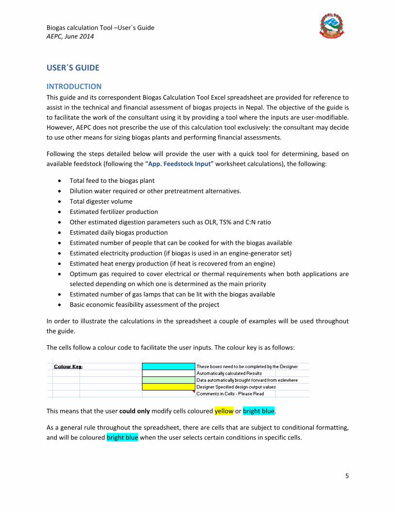
The cells follow a colour code to facilitate the user inputs. The colour key is as follows:
This means that the user could only modify cells coloured yellow or bright blue.
As a general rule throughout the spreadsheet, there are cells that are subject to conditional formatting, and will be coloured bright blue when the user selects certain conditions in specific cells.

Biogas calculation Tool –User´s Guide AEPC, June 2014
6
Lastly, the following button, located in the top right hand corner of each worksheet, shall be pressed whenever the user would like to clear the inputs and start the calculations again. The macro will delete all user inputs in the blue cells in that particular worksheet.
For any questions about this guide or the spreadsheet, please contact:
Victor Olmos Garcia Biogas and Waste to Energy Technical Adviser – Alternative Energy Promotion Center
Ministry of Science, Technology and Environment Government of Nepal
Phone number: 9801007891 [email protected]
Biogas calculation Tool –User´s Guide AEPC, June 2014
7
TECHNICAL ASSESSMENT
“1. WASTE CHAR. + ENERGY DEMAND” WORKSHEET
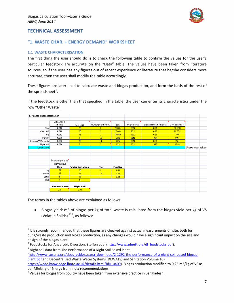
1.1 WASTE CHARACTERISATION The first thing the user should do is to check the following table to confirm the values for the user’s particular feedstock are accurate on the “Data” table. The values have been taken from literature sources, so if the user has any figures out of recent experience or literature that he/she considers more accurate, then the user shall modify the table accordingly.
These figures are later used to calculate waste and biogas production, and form the basis of the rest of the spreadsheet1
The terms in the tables above are explained as follows:
.
If the feedstock is other than that specified in the table, the user can enter its characteristics under the row “Other Waste”.
• Biogas yield: m3 of biogas per kg of total waste is calculated from the biogas yield per kg of VS (Volatile Solids) 234
1 It is strongly recommended that these figures are checked against actual measurements on site, both for dung/waste production and biogas production, as any changes would have a significant impact on the size and design of the biogas plant.
, as follows:
2 Feedstocks for Anaerobic Digestion, Steffen et al (http://www.adnett.org/dl_feedstocks.pdf). 3 Night soil data from The Performance of a Night Soil Based Plant (http://www.susana.org/docs_ccbk/susana_download/2-1292-the-performance-of-a-night-soil-based-biogas-plant.pdf and Decentralised Waste Water Systems (DEWATS) and Sanitation Volume 10 ( https://wedc-knowledge.lboro.ac.uk/details.html?id=10409). Biogas production modified to 0.25 m3/kg of VS as per Ministry of Energy from India recommendations. 4 Values for biogas from poultry have been taken from extensive practice in Bangladesh.

Biogas calculation Tool –User´s Guide AEPC, June 2014
8
𝐵𝐵𝐵𝐵𝐵𝐵𝐵𝐵𝐵𝐵𝐵𝐵 𝑦𝑦𝐵𝐵𝑦𝑦𝑦𝑦𝑦𝑦 (𝑚𝑚3/𝑘𝑘𝐵𝐵 𝐵𝐵𝑜𝑜 𝑤𝑤𝐵𝐵𝐵𝐵𝑤𝑤𝑦𝑦) = 𝐵𝐵𝐵𝐵𝐵𝐵𝐵𝐵𝐵𝐵𝐵𝐵 𝑦𝑦𝐵𝐵𝑦𝑦𝑦𝑦𝑦𝑦 �𝑚𝑚3
𝑘𝑘𝐵𝐵 𝐵𝐵𝑜𝑜 𝑉𝑉𝑉𝑉� ∗ 𝑇𝑇𝑉𝑉(%) ∗ 𝑉𝑉𝑉𝑉(%)
Therefore, if the user has different values for specific biogas production, the user shall modify the column “Biogas Yield (m3/kg of VS)”.
• C:N ratio: Carbon to Nitrogen ratio5
• OLR: Organic Loading Rate, kg of Volatile Solids/m3 of digester. Determines the maximum organic loading rate for each type of feedstock.
of the feedstock
6
• TS%, VS%: Total Solids % and Volatile Solids % (the latter as a % of the Total Solids)
2 • CH4 content: methane content on the gas mixture (for indicative purposes only) 2 above • The table manure per head per day production above specifies how much manure is produced
per animal as a function of its size.789
1.2 ENERGY DEMAND Here the user is asked to enter the current energy demand, either in the form of electricity or heating (cooking, etc), that the owner/developer current has and would like biogas to replace. The user shall fill in the following table (filled in for illustration purposes):
As it can be seen from the table above, when answering “Yes” to the question on electrical savings, the electricity demand table will be coloured bright blue for the user to enter the inputs. The total wattage installed is calculated as 𝑛𝑛𝑛𝑛𝑚𝑚𝑛𝑛𝑦𝑦𝑛𝑛 𝐵𝐵𝑜𝑜 𝐵𝐵𝑤𝑤𝑦𝑦𝑚𝑚𝐵𝐵 ∗ 𝑛𝑛𝐵𝐵𝑤𝑤𝐵𝐵𝑛𝑛𝐵𝐵 (𝑤𝑤), and the consumption is calculated as the product of 𝑤𝑤 𝐵𝐵𝑛𝑛𝐵𝐵𝑤𝑤𝐵𝐵𝑦𝑦𝑦𝑦𝑦𝑦𝑦𝑦 ∗ ℎ𝐵𝐵𝑛𝑛𝑛𝑛𝐵𝐵 𝑛𝑛𝑛𝑛𝑛𝑛 𝑝𝑝𝑦𝑦𝑛𝑛 𝑦𝑦𝐵𝐵𝑦𝑦.
5 Biogas Digest, Volume I, Biogas Basics – GTZ (http://www.biores.eu/docs/BIOGASFUNDAMENTALS/biogasdigestvol1.pdf) 6 Anaerobic digestion in poultry and livestock waste treatment - a literature review, Salkar, Yetilmezsoy, Kocak 7 Detailed Feasibility Study of Biogas Power Generation from Poultry Waste in the Poultry Farms – Sustainable Energy and Technology Management (SETM – 2011). 8 Figures for organic waste production from “Integrated Waste to Energy Project Investment Plan” – Sushila Maharjan, World Bank – Nepal 2013 9 Figures for night soild production per capita from Treatment Technologies for Human Faeces and Urine, Niwagaba, Swedish University of Agricultural Sciences, 2009 (http://pub.epsilon.slu.se/2177/1/niwagaba_c_091123.pdf)
Biogas calculation Tool –User´s Guide AEPC, June 2014
9
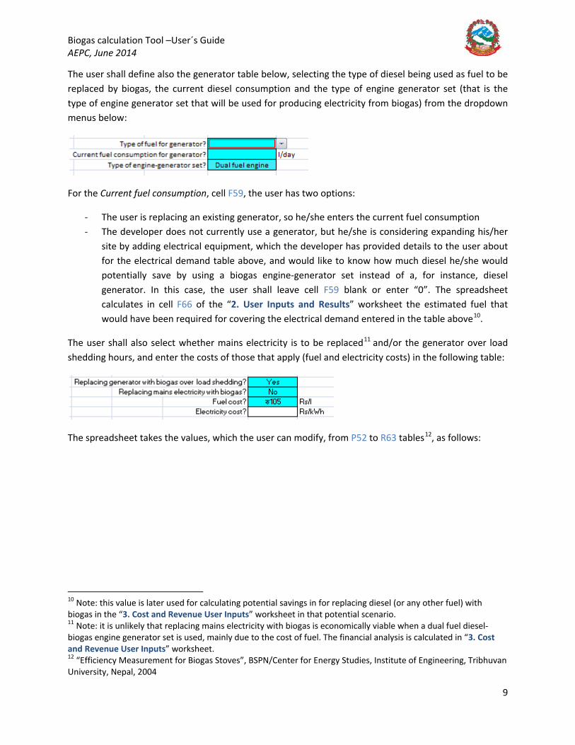
The user shall define also the generator table below, selecting the type of diesel being used as fuel to be replaced by biogas, the current diesel consumption and the type of engine generator set (that is the type of engine generator set that will be used for producing electricity from biogas) from the dropdown menus below:
For the Current fuel consumption, cell F59, the user has two options:
- The user is replacing an existing generator, so he/she enters the current fuel consumption - The developer does not currently use a generator, but he/she is considering expanding his/her
site by adding electrical equipment, which the developer has provided details to the user about for the electrical demand table above, and would like to know how much diesel he/she would potentially save by using a biogas engine-generator set instead of a, for instance, diesel generator. In this case, the user shall leave cell F59 blank or enter “0”. The spreadsheet calculates in cell F66 of the “2. User Inputs and Results” worksheet the estimated fuel that would have been required for covering the electrical demand entered in the table above10
The user shall also select whether mains electricity is to be replaced
.
11
and/or the generator over load shedding hours, and enter the costs of those that apply (fuel and electricity costs) in the following table:
The spreadsheet takes the values, which the user can modify, from P52 to R63 tables12
10 Note: this value is later used for calculating potential savings in for replacing diesel (or any other fuel) with biogas in the “3. Cost and Revenue User Inputs” worksheet in that potential scenario. 11 Note: it is unlikely that replacing mains electricity with biogas is economically viable when a dual fuel diesel-biogas engine generator set is used, mainly due to the cost of fuel. The financial analysis is calculated in “3. Cost and Revenue User Inputs” worksheet. 12 “Efficiency Measurement for Biogas Stoves”, BSPN/Center for Energy Studies, Institute of Engineering, Tribhuvan University, Nepal, 2004
, as follows:
Biogas calculation Tool –User´s Guide AEPC, June 2014
10
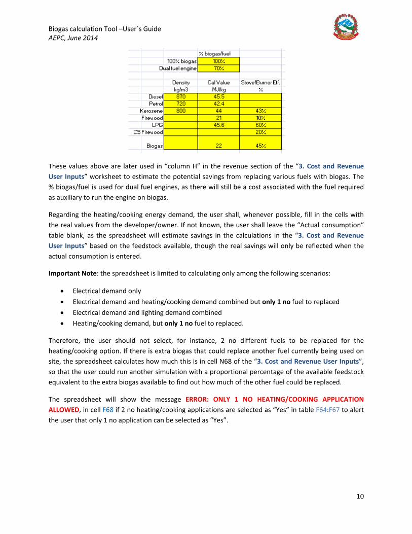
These values above are later used in “column H” in the revenue section of the “3. Cost and Revenue User Inputs” worksheet to estimate the potential savings from replacing various fuels with biogas. The % biogas/fuel is used for dual fuel engines, as there will still be a cost associated with the fuel required as auxiliary to run the engine on biogas.
Regarding the heating/cooking energy demand, the user shall, whenever possible, fill in the cells with the real values from the developer/owner. If not known, the user shall leave the “Actual consumption” table blank, as the spreadsheet will estimate savings in the calculations in the “3. Cost and Revenue User Inputs” based on the feedstock available, though the real savings will only be reflected when the actual consumption is entered.
Important Note: the spreadsheet is limited to calculating only among the following scenarios:
• Electrical demand only • Electrical demand and heating/cooking demand combined but only 1 no fuel to replaced • Electrical demand and lighting demand combined • Heating/cooking demand, but only 1 no fuel to replaced.
Therefore, the user should not select, for instance, 2 no different fuels to be replaced for the heating/cooking option. If there is extra biogas that could replace another fuel currently being used on site, the spreadsheet calculates how much this is in cell N68 of the “3. Cost and Revenue User Inputs”, so that the user could run another simulation with a proportional percentage of the available feedstock equivalent to the extra biogas available to find out how much of the other fuel could be replaced.
The spreadsheet will show the message ERROR: ONLY 1 NO HEATING/COOKING APPLICATION ALLOWED, in cell F68 if 2 no heating/cooking applications are selected as “Yes” in table F64:F67 to alert the user that only 1 no application can be selected as “Yes”.
Biogas calculation Tool –User´s Guide AEPC, June 2014
11
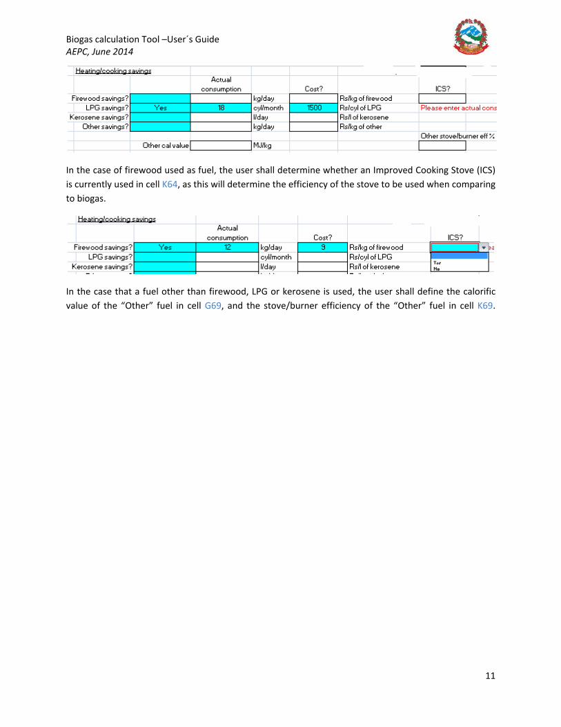
In the case of firewood used as fuel, the user shall determine whether an Improved Cooking Stove (ICS) is currently used in cell K64, as this will determine the efficiency of the stove to be used when comparing to biogas.
In the case that a fuel other than firewood, LPG or kerosene is used, the user shall define the calorific value of the “Other” fuel in cell G69, and the stove/burner efficiency of the “Other” fuel in cell K69.
Biogas calculation Tool –User´s Guide AEPC, June 2014
12
2. “2. USER INPUTS AND RESULTS” WORKSHEET This is the main worksheet where the user has to enter the feedstock available, the characteristics of the plant and the gas application. The worksheet returns the main results such as the size of the plant, potential for gas utilization and main process stream characteristics.
2.1. Define Feedstock Available The user shall specify the number of animals whose waste will be collected to feed the biogas plant and, if the biogas plant also treats toilet and/or organic waste from a residential complex, the user shall also specify the requested parameters under the “Population” table.
“Population” table explained: Whenever organic waste and/or toilet waste are treated in the biogas plant, the user needs to fill in this table.
For a given population number entered by the user (the number of students and staff from a school, or the number of soldiers in an army barracks, for instance), the spreadsheet calculates the population equivalent figures (table F32:G33) based on the number of shifts there are. For example, if the school is attended by students only during the day, the user must input “Number of Shifts” = 1, so the population equivalent will be half of that specified in the population table. If the school is a boarding school where the students and staff consume all their daily meals, the user shall input “Number of Shifts = 2”, so the population equivalent figure will equal that of the population table (in this case, the total number of students and staff of the school). The same principle applies to other residential complexes such as prisons, army barracks, hotels, etc.
If kitchen waste is treated in the biogas plant, but the user does not know the exact amount produced, cell K27 shall be left blank so that the spreadsheet would use the per capita production value from the “1. Waste Char. + Energy Demand” worksheet. If the user, however, knows the amount of kitchen/MSW waste produced, then this value should be entered in K27 so that the spreadsheet uses this figure in further calculations instead of the per capita production.
If toilet waste is to be treated in the biogas plant, the user shall select “Yes” from the “Toilet Waste” dropdown menu in cell K28. The population equivalent value will be multiplied by the per capita production of night soil from the “1. Waste Char. + Energy Demand” worksheet to calculate the total toilet waste produced in cell G33.
If toilet waste is to be treated, the user shall also define the type of toilet, either as an “Auto flushing” toilet (such as western toilets) or a “Pour flushing” toilet (where buckets of water are manually poured to flush the toilet). The amount of water for these toilets has been defined in “App. MB and Pretreatment” worksheet cells F3:F7, containing the assumed values; these values must be checked by the user and modify accordingly to match the site conditions. How the “App. MB and Pretreatment” worksheet operates will be explained in a later section (APPENDIX A – “APP. MB AND PRETREATMENT” AND “APP. FEEDSTOCK INPUT” WORKSHEETS).
Biogas calculation Tool –User´s Guide AEPC, June 2014
13
In the event of toilet waste being treated, if the liquid content is too high, diluting the substrate in excess and therefore result in an oversized digester, the “Population table” also returns, from the “App. MB and Pretreatment”, whether a pretreatment, thickening stage would be needed in the form of a settlement basin. If this technology is not available or suitable, whenever cell K30 returns the message “Yes thick/DEWATS?, no dil water”, the user shall make a decision on whether a thickening stage or other alternatives for removing water (such as reducing flushing water from the toilets) are available; it this is not the case, the user is encouraged to explore other alternatives such as DEWATS (Decentralised Wastewater Treatment Plants), change the retention time or disregard the treatment of toilet waste altogether, by changing cell K28 to “No”.
An example will be used throughout the document to show how to use the tool in practice and illustrate the explanations of the calculations.
Example 1 – School (From “1. Waste Char.+ Energy Demand” worksheet to “2.1, Define feedstock available” in “User Inputs and Results” worksheet): Let’s see how a user could follow the requirements to fill 2.1 above.
The case to be used along the guide would be that of a school of the following characteristics:
“A school in the Terai, of 220 students and 30 staff, who only go to lessons over half a day, has 20 middle-sized cows and 10 small pigs. The principal of the school states that they produce 25 kg of kitchen waste per day and that they have a farm adjacent with 20 middle-sized cows and 10 big pigs. She would like to build a biogas plant to cook food for the staff and the students, who eat only lunch at the school, so she would like to know how many of them she could cook for. Also, she states that she wonders if she could also feed toilet waste from pour-flush toilets to the digester. She also states that she is currently spending 18 LPG cylinders per month for cooking purposes”.
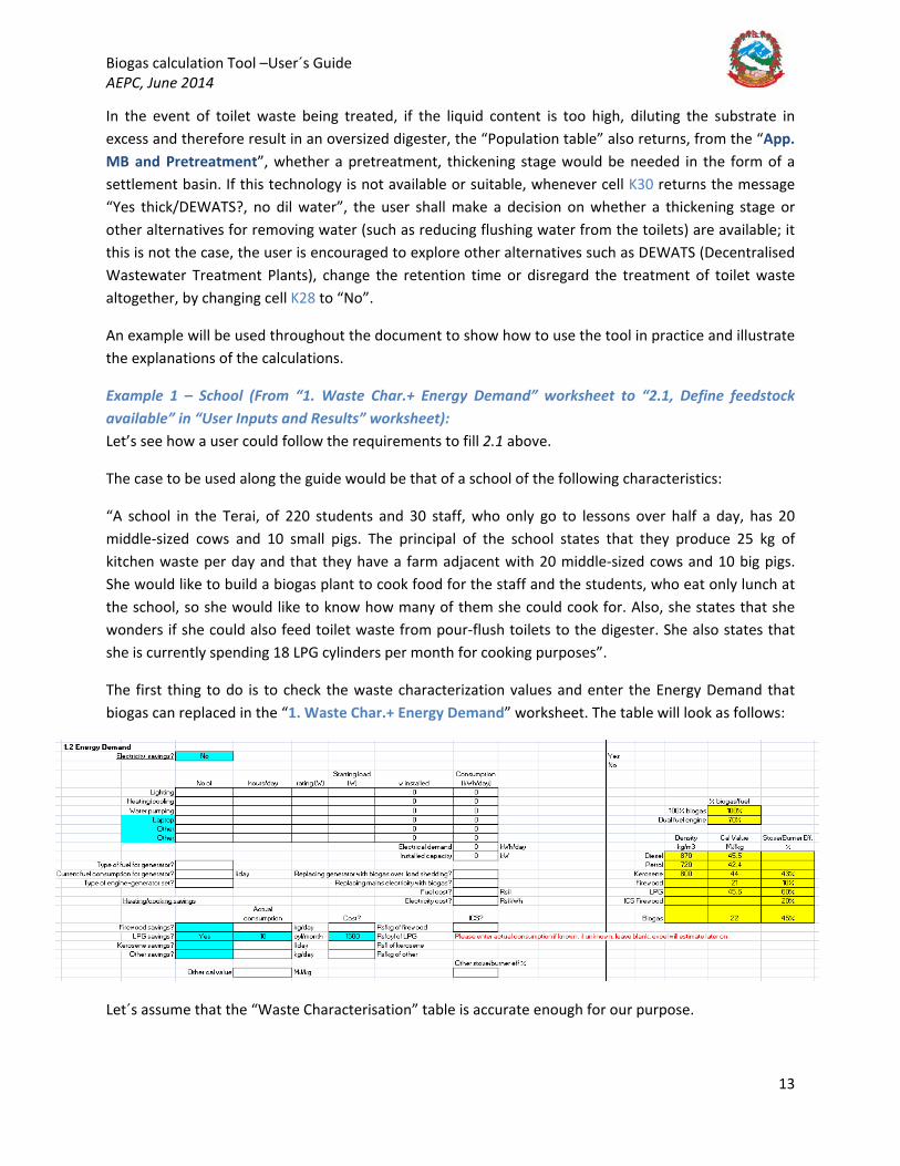
The first thing to do is to check the waste characterization values and enter the Energy Demand that biogas can replaced in the “1. Waste Char.+ Energy Demand” worksheet. The table will look as follows:
Let´s assume that the “Waste Characterisation” table is accurate enough for our purpose.
Biogas calculation Tool –User´s Guide AEPC, June 2014
14
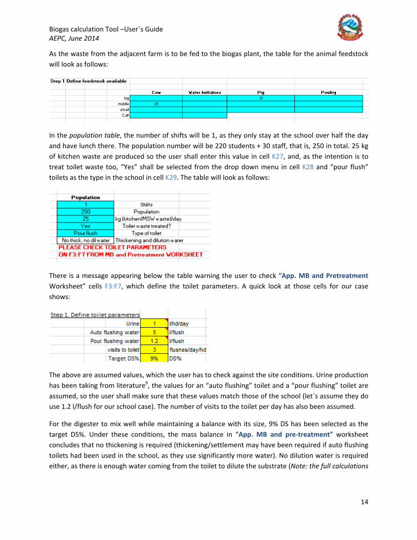
As the waste from the adjacent farm is to be fed to the biogas plant, the table for the animal feedstock will look as follows:
In the population table, the number of shifts will be 1, as they only stay at the school over half the day and have lunch there. The population number will be 220 students + 30 staff, that is, 250 in total. 25 kg of kitchen waste are produced so the user shall enter this value in cell K27, and, as the intention is to treat toilet waste too, “Yes” shall be selected from the drop down menu in cell K28 and “pour flush” toilets as the type in the school in cell K29. The table will look as follows:
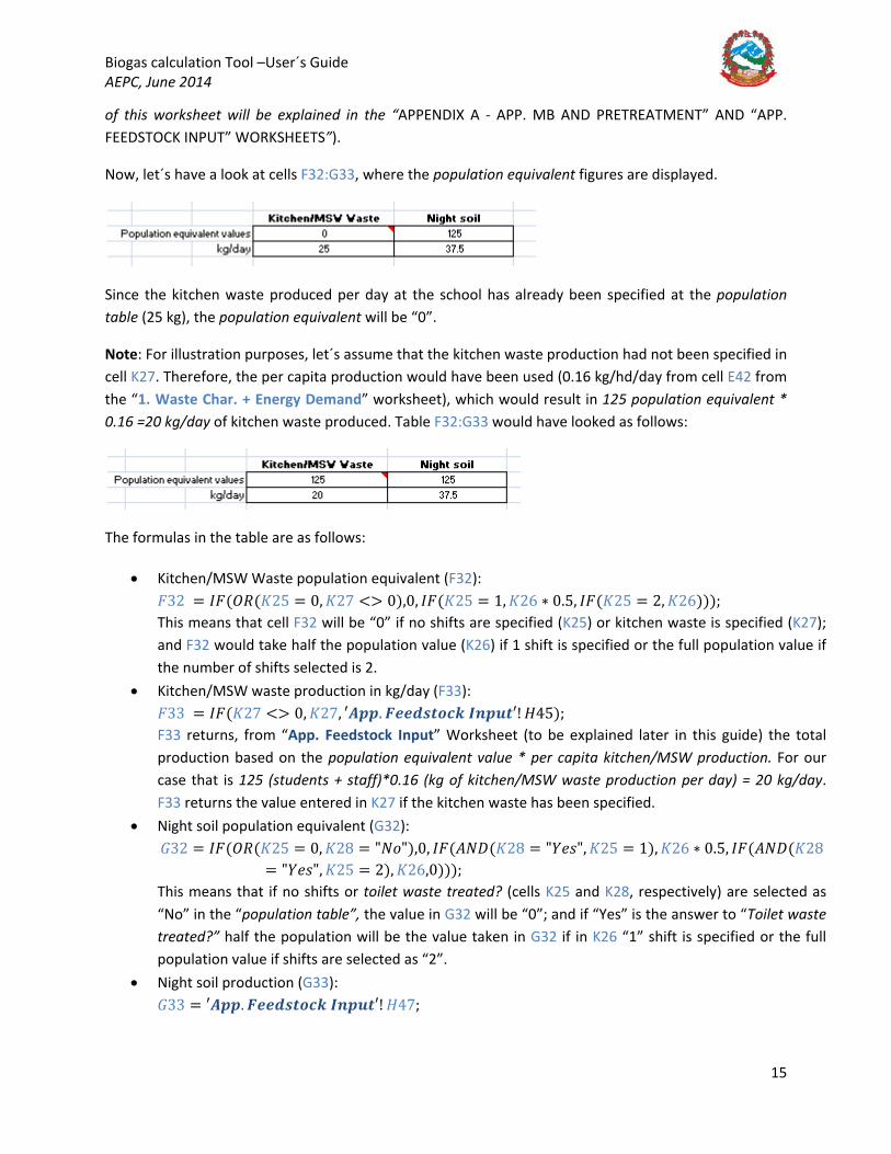
There is a message appearing below the table warning the user to check “App. MB and Pretreatment Worksheet” cells F3:F7, which define the toilet parameters. A quick look at those cells for our case shows:
The above are assumed values, which the user has to check against the site conditions. Urine production has been taking from literature9, the values for an “auto flushing” toilet and a “pour flushing” toilet are assumed, so the user shall make sure that these values match those of the school (let´s assume they do use 1.2 l/flush for our school case). The number of visits to the toilet per day has also been assumed.
For the digester to mix well while maintaining a balance with its size, 9% DS has been selected as the target DS%. Under these conditions, the mass balance in “App. MB and pre-treatment” worksheet concludes that no thickening is required (thickening/settlement may have been required if auto flushing toilets had been used in the school, as they use significantly more water). No dilution water is required either, as there is enough water coming from the toilet to dilute the substrate (Note: the full calculations
Biogas calculation Tool –User´s Guide AEPC, June 2014
15
of this worksheet will be explained in the “APPENDIX A - APP. MB AND PRETREATMENT” AND “APP. FEEDSTOCK INPUT” WORKSHEETS”).
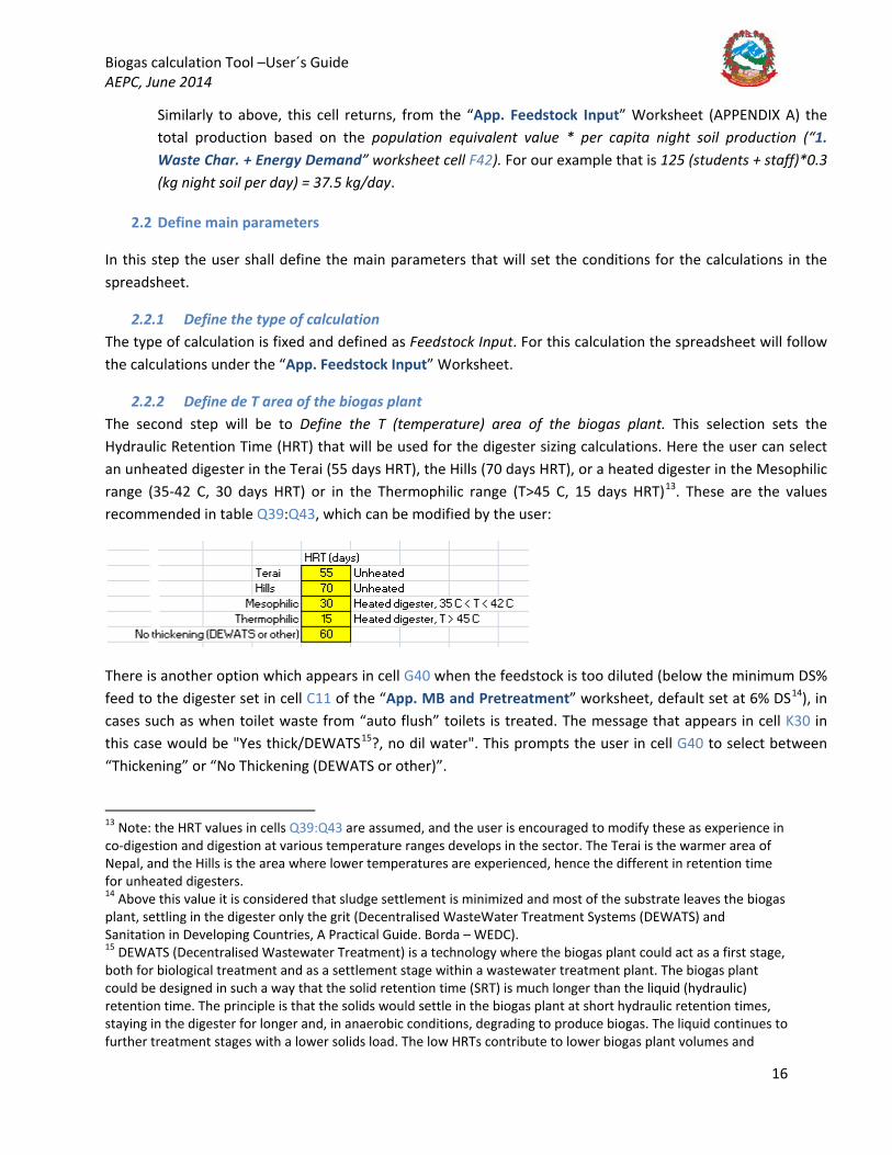
Now, let´s have a look at cells F32:G33, where the population equivalent figures are displayed.
Since the kitchen waste produced per day at the school has already been specified at the population table (25 kg), the population equivalent will be “0”.
Note: For illustration purposes, let´s assume that the kitchen waste production had not been specified in cell K27. Therefore, the per capita production would have been used (0.16 kg/hd/day from cell E42 from the “1. Waste Char. + Energy Demand” worksheet), which would result in 125 population equivalent * 0.16 =20 kg/day of kitchen waste produced. Table F32:G33 would have looked as follows:
The formulas in the table are as follows:
• Kitchen/MSW Waste population equivalent (F32): 𝐹𝐹32 = 𝐼𝐼𝐹𝐹(𝑂𝑂𝑂𝑂(𝐾𝐾25 = 0, 𝐾𝐾27 <> 0),0, 𝐼𝐼𝐹𝐹(𝐾𝐾25 = 1, 𝐾𝐾26 ∗ 0.5, 𝐼𝐼𝐹𝐹(𝐾𝐾25 = 2, 𝐾𝐾26))); This means that cell F32 will be “0” if no shifts are specified (K25) or kitchen waste is specified (K27); and F32 would take half the population value (K26) if 1 shift is specified or the full population value if the number of shifts selected is 2.
• Kitchen/MSW waste production in kg/day (F33): 𝐹𝐹33 = 𝐼𝐼𝐹𝐹(𝐾𝐾27 <> 0, 𝐾𝐾27, ′𝑨𝑨𝑨𝑨𝑨𝑨. 𝑭𝑭𝑭𝑭𝑭𝑭𝑭𝑭𝑭𝑭𝑭𝑭𝑭𝑭𝑭𝑭𝑭𝑭 𝑰𝑰𝑰𝑰𝑨𝑨𝑰𝑰𝑭𝑭′! 𝐻𝐻45); F33 returns, from “App. Feedstock Input” Worksheet (to be explained later in this guide) the total production based on the population equivalent value * per capita kitchen/MSW production. For our case that is 125 (students + staff)*0.16 (kg of kitchen/MSW waste production per day) = 20 kg/day. F33 returns the value entered in K27 if the kitchen waste has been specified.
• Night soil population equivalent (G32): 𝐺𝐺32 = 𝐼𝐼𝐹𝐹(𝑂𝑂𝑂𝑂(𝐾𝐾25 = 0, 𝐾𝐾28 = "𝑁𝑁𝐵𝐵"),0, 𝐼𝐼𝐹𝐹(𝐴𝐴𝑁𝑁𝐴𝐴(𝐾𝐾28 = "𝑌𝑌𝑦𝑦𝐵𝐵", 𝐾𝐾25 = 1), 𝐾𝐾26 ∗ 0.5, 𝐼𝐼𝐹𝐹(𝐴𝐴𝑁𝑁𝐴𝐴(𝐾𝐾28
= "𝑌𝑌𝑦𝑦𝐵𝐵", 𝐾𝐾25 = 2), 𝐾𝐾26,0))); This means that if no shifts or toilet waste treated? (cells K25 and K28, respectively) are selected as “No” in the “population table”, the value in G32 will be “0”; and if “Yes” is the answer to “Toilet waste treated?” half the population will be the value taken in G32 if in K26 “1” shift is specified or the full population value if shifts are selected as “2”.
• Night soil production (G33): 𝐺𝐺33 = ′𝑨𝑨𝑨𝑨𝑨𝑨. 𝑭𝑭𝑭𝑭𝑭𝑭𝑭𝑭𝑭𝑭𝑭𝑭𝑭𝑭𝑭𝑭𝑭𝑭 𝑰𝑰𝑰𝑰𝑨𝑨𝑰𝑰𝑭𝑭′! 𝐻𝐻47;
Biogas calculation Tool –User´s Guide AEPC, June 2014
16
Similarly to above, this cell returns, from the “App. Feedstock Input” Worksheet (APPENDIX A) the total production based on the population equivalent value * per capita night soil production (“1. Waste Char. + Energy Demand” worksheet cell F42). For our example that is 125 (students + staff)*0.3 (kg night soil per day) = 37.5 kg/day.
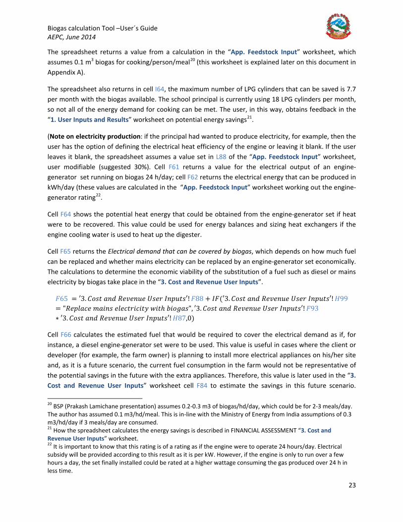
2.2 Define main parameters
In this step the user shall define the main parameters that will set the conditions for the calculations in the spreadsheet.
2.2.1 Define the type of calculation The type of calculation is fixed and defined as Feedstock Input. For this calculation the spreadsheet will follow the calculations under the “App. Feedstock Input” Worksheet.
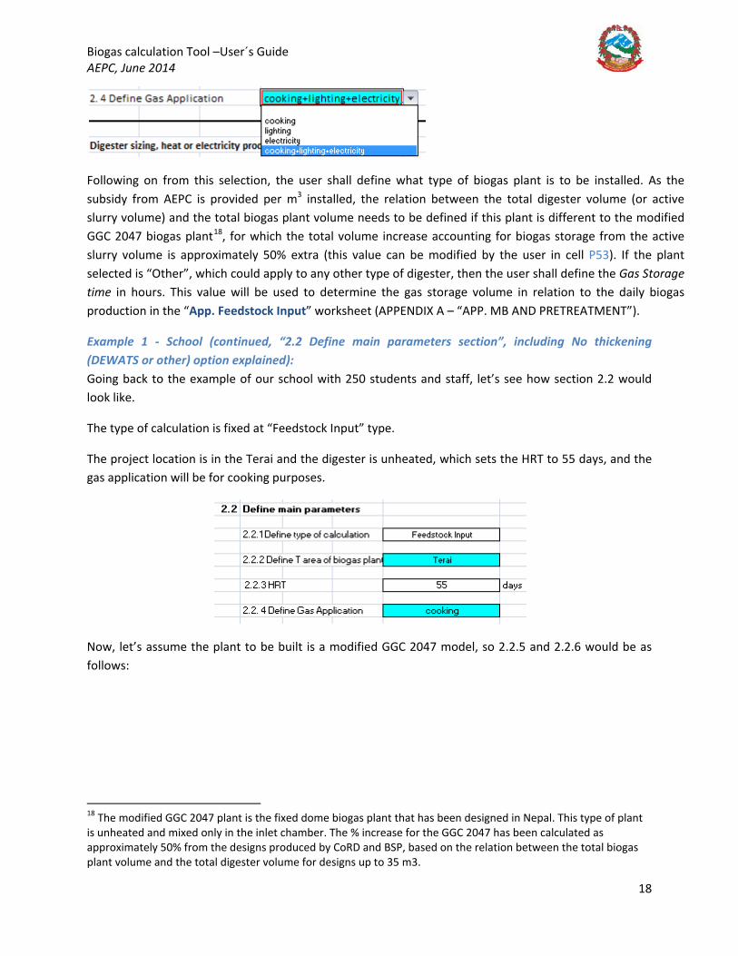
2.2.2 Define de T area of the biogas plant The second step will be to Define the T (temperature) area of the biogas plant. This selection sets the Hydraulic Retention Time (HRT) that will be used for the digester sizing calculations. Here the user can select an unheated digester in the Terai (55 days HRT), the Hills (70 days HRT), or a heated digester in the Mesophilic range (35-42 C, 30 days HRT) or in the Thermophilic range (T>45 C, 15 days HRT)13
. These are the values recommended in table Q39:Q43, which can be modified by the user:
There is another option which appears in cell G40 when the feedstock is too diluted (below the minimum DS% feed to the digester set in cell C11 of the “App. MB and Pretreatment” worksheet, default set at 6% DS14), in cases such as when toilet waste from “auto flush” toilets is treated. The message that appears in cell K30 in this case would be "Yes thick/DEWATS15
13 Note: the HRT values in cells Q39:Q43 are assumed, and the user is encouraged to modify these as experience in co-digestion and digestion at various temperature ranges develops in the sector. The Terai is the warmer area of Nepal, and the Hills is the area where lower temperatures are experienced, hence the different in retention time for unheated digesters. 14 Above this value it is considered that sludge settlement is minimized and most of the substrate leaves the biogas plant, settling in the digester only the grit (Decentralised WasteWater Treatment Systems (DEWATS) and Sanitation in Developing Countries, A Practical Guide. Borda – WEDC).
?, no dil water". This prompts the user in cell G40 to select between “Thickening” or “No Thickening (DEWATS or other)”.
15 DEWATS (Decentralised Wastewater Treatment) is a technology where the biogas plant could act as a first stage, both for biological treatment and as a settlement stage within a wastewater treatment plant. The biogas plant could be designed in such a way that the solid retention time (SRT) is much longer than the liquid (hydraulic) retention time. The principle is that the solids would settle in the biogas plant at short hydraulic retention times, staying in the digester for longer and, in anaerobic conditions, degrading to produce biogas. The liquid continues to further treatment stages with a lower solids load. The low HRTs contribute to lower biogas plant volumes and

Biogas calculation Tool –User´s Guide AEPC, June 2014
17
If the user selects “Thickening”16
If the user selects “No thickening (DEWATS or other)”, this means that the feed will not be thickened, and will be fed to the digester in whatever DS% the mixture of toilet waste and other waste is (cell F10 in “App. MB and Pretreatment”) as in a DEWATS plant. In this case, the user is asked to check the HRT recommended in cell Q43 by a message that appears in cell G41 “Check HRT in Q43”. The HRT recommended for a DEWATS plant is 60 days in Q43
, the spreadsheet will calculate how much the toilet waste needs to be thickened in order to achieve the feed DS% to the digester equal to the target value set in cell F7 of the “App. MB and Pretreatment” worksheet (9% DS recommended). For this option, the user shall select the T area of the biogas plant in cell F40 as well as this will set the HRT in cell F42.
17
2.2.3 HRT (Hydraulic Retention Time)
, though the user must decide and change this value depending on what the most suitable HRT is based on each particular case (for instance, if the biogas plant design allows for long SRTs which may favour short HRTs reducing the capital cost). This HRT selection will ignore the temperature area selected in cell F40 and only consider that from Q43, so it is important that the user checks and modifies carefully the HRT recommended in this cell.
Based on the above considerations, the HRT shall be calculated as follows:
𝐹𝐹42 = 𝐻𝐻𝑂𝑂𝑇𝑇 = 𝐼𝐼𝐹𝐹(𝐴𝐴𝑁𝑁𝐴𝐴(𝐾𝐾30 = "𝑌𝑌𝑦𝑦𝐵𝐵 𝑤𝑤ℎ𝐵𝐵𝑖𝑖𝑘𝑘/𝐴𝐴𝐷𝐷𝐷𝐷𝐴𝐴𝑇𝑇𝑉𝑉? , 𝑛𝑛𝐵𝐵 𝑦𝑦𝐵𝐵𝑦𝑦 𝑤𝑤𝐵𝐵𝑤𝑤𝑦𝑦𝑛𝑛", 𝐺𝐺40= "𝑁𝑁𝐵𝐵 𝑤𝑤ℎ𝐵𝐵𝑖𝑖𝑘𝑘𝑦𝑦𝑛𝑛𝐵𝐵𝑛𝑛𝐵𝐵 (𝐴𝐴𝐷𝐷𝐷𝐷𝐴𝐴𝑇𝑇𝑉𝑉 𝐵𝐵𝑛𝑛 𝐵𝐵𝑤𝑤ℎ𝑦𝑦𝑛𝑛)"), 𝑄𝑄43, 𝐼𝐼𝐹𝐹(𝑂𝑂𝑂𝑂(𝐾𝐾30= "𝑁𝑁𝐵𝐵 𝑤𝑤ℎ𝐵𝐵𝑖𝑖𝑘𝑘, 𝑛𝑛𝐵𝐵 𝑦𝑦𝐵𝐵𝑦𝑦 𝑤𝑤𝐵𝐵𝑤𝑤𝑦𝑦𝑛𝑛", 𝐾𝐾30 = "𝑁𝑁𝐵𝐵 𝑤𝑤ℎ𝐵𝐵𝑖𝑖𝑘𝑘, 𝑦𝑦𝑦𝑦𝐵𝐵 𝑦𝑦𝐵𝐵𝑦𝑦 𝑤𝑤𝐵𝐵𝑤𝑤𝑦𝑦𝑛𝑛", 𝐺𝐺40= "𝑤𝑤ℎ𝐵𝐵𝑖𝑖𝑘𝑘𝑦𝑦𝑛𝑛𝐵𝐵𝑛𝑛𝐵𝐵"), 𝐼𝐼𝐹𝐹(𝐹𝐹40 = "𝑇𝑇𝑦𝑦𝑛𝑛𝐵𝐵𝐵𝐵", 𝑄𝑄39, 𝐼𝐼𝐹𝐹(𝐹𝐹40 = "𝐻𝐻𝐵𝐵𝑦𝑦𝑦𝑦𝐵𝐵", 𝑄𝑄40, 𝐼𝐼𝐹𝐹(𝐹𝐹40= "𝑀𝑀𝑦𝑦𝐵𝐵𝐵𝐵𝑝𝑝ℎ𝐵𝐵𝑦𝑦𝐵𝐵𝑖𝑖", 𝑄𝑄41, 𝐼𝐼𝐹𝐹(𝐹𝐹40 = "𝑇𝑇ℎ𝑦𝑦𝑛𝑛𝑚𝑚𝐵𝐵𝑝𝑝ℎ𝐵𝐵𝑦𝑦𝐵𝐵𝑖𝑖", 𝑄𝑄42,0))))))
2.2.4 Define Gas Application In this section, the user shall Define the gas application, for which he/she can select among cooking, lighting or electricity production or cooking+lighting+electricity from the dropdown menu.
therefore to lower capital cost, while solids settle in the digester. For instance, the design of the DEWATS plant at Shrikandapur in Dulikhel, Nepal, assumes 1 day HRT for the liquid fraction; 2 days recommended as a more conservative value However, more conservative HRTs should be selected if no modifications to the biogas plant to favour long SRTs are carried out. Detailed information on DEWATS can be found in: https://wedc-knowledge.lboro.ac.uk/details.html?id=10409 16 For instance, a primary settlement tank or a belt or drum thickener of a wastewater treatment plant. 17 The design of the DEWATS plant at Shrikandapur in Dulikhel, Nepal, assumes 1 day HRT for the liquid fraction; 2 days recommended as a more conservative value.
Biogas calculation Tool –User´s Guide AEPC, June 2014
18
Following on from this selection, the user shall define what type of biogas plant is to be installed. As the subsidy from AEPC is provided per m3 installed, the relation between the total digester volume (or active slurry volume) and the total biogas plant volume needs to be defined if this plant is different to the modified GGC 2047 biogas plant18
Example 1 - School (continued, “2.2 Define main parameters section”, including No thickening (DEWATS or other) option explained):
, for which the total volume increase accounting for biogas storage from the active slurry volume is approximately 50% extra (this value can be modified by the user in cell P53). If the plant selected is “Other”, which could apply to any other type of digester, then the user shall define the Gas Storage time in hours. This value will be used to determine the gas storage volume in relation to the daily biogas production in the “App. Feedstock Input” worksheet (APPENDIX A – “APP. MB AND PRETREATMENT”).
Going back to the example of our school with 250 students and staff, let’s see how section 2.2 would look like.
The type of calculation is fixed at “Feedstock Input” type.
The project location is in the Terai and the digester is unheated, which sets the HRT to 55 days, and the gas application will be for cooking purposes.
Now, let’s assume the plant to be built is a modified GGC 2047 model, so 2.2.5 and 2.2.6 would be as follows:
18 The modified GGC 2047 plant is the fixed dome biogas plant that has been designed in Nepal. This type of plant is unheated and mixed only in the inlet chamber. The % increase for the GGC 2047 has been calculated as approximately 50% from the designs produced by CoRD and BSP, based on the relation between the total biogas plant volume and the total digester volume for designs up to 35 m3.

Biogas calculation Tool –User´s Guide AEPC, June 2014
19
(Note: if the plant selected had been other than the GGC 2047 model, the user shall enter the gas storage time in cell K40, in hours, for the type of plant chosen, which will be accounted for, together with the daily biogas production, in order to calculate the gas storage volume. The spreadsheet will colour K40 bright blue to indicate the user to enter a value:
).
No Thickening (DEWATS or other) explained: Let´s now assume that the school has no cows or pigs, and that 1000 students attend the school and stay there overnight (2 no shifts). The population table would look as follows:
Cell K30, following the calculations from the “App. MB and Pretreatment” worksheet, states that the substrate is too diluted and recommends exploring other options such as thickening, DEWATS or other technology by showing the message “Yes thick/DEWATS?, no dil water”. No extra dilution water is required as the substrate is already too diluted. From the “App. MB and Pretreatment” worksheet, the toilet parameters are:

Biogas calculation Tool –User´s Guide AEPC, June 2014
20
The Digester Feed DS% in cell F10 is 0.5%. The user now has two options in cell G40 of the “User Inputs and Results” worksheet:
Let´s assume the user decides that the biogas plant will be the first stage of a DEWATS plant. In this case, the HRT selected will be 60 days. This will have an impact on the digester volume as calculated in the “App Feedstock Input” worksheet. It also affects the calculations carried out in the “App. MB and Pretreatment” worksheet as explained in APPENDIX A below.
If the user had decided to select the thickening option (such as primary settlement tank or other mechanical thickening equipment), the spreadsheet would follow the calculations in the “App. MB and Pretreatment” worksheet, and the toilet waste shall be thickened to achieve the target DS% of 9% DS (this accounts for mixing with other waste too). The retention time assumed will be that of the temperature area defined in F40, in this case, the Terai:
Biogas calculation Tool –User´s Guide AEPC, June 2014
21
2.3 Digester sizing, heat or electricity production
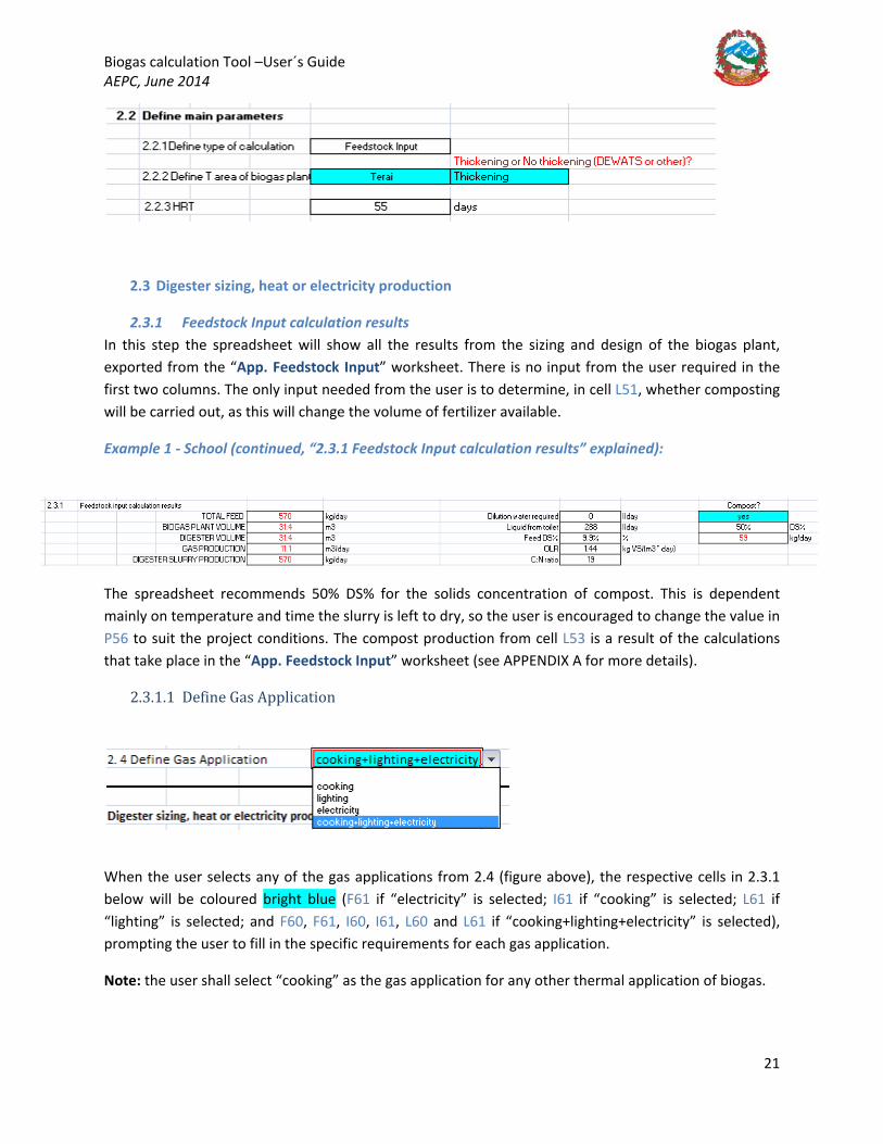
2.3.1 Feedstock Input calculation results In this step the spreadsheet will show all the results from the sizing and design of the biogas plant, exported from the “App. Feedstock Input” worksheet. There is no input from the user required in the first two columns. The only input needed from the user is to determine, in cell L51, whether composting will be carried out, as this will change the volume of fertilizer available.
Example 1 - School (continued, “2.3.1 Feedstock Input calculation results” explained):
The spreadsheet recommends 50% DS% for the solids concentration of compost. This is dependent mainly on temperature and time the slurry is left to dry, so the user is encouraged to change the value in P56 to suit the project conditions. The compost production from cell L53 is a result of the calculations that take place in the “App. Feedstock Input” worksheet (see APPENDIX A for more details).
2.3.1.1 Define Gas Application
When the user selects any of the gas applications from 2.4 (figure above), the respective cells in 2.3.1 below will be coloured bright blue (F61 if “electricity” is selected; I61 if “cooking” is selected; L61 if “lighting” is selected; and F60, F61, I60, I61, L60 and L61 if “cooking+lighting+electricity” is selected), prompting the user to fill in the specific requirements for each gas application.
Note: the user shall select “cooking” as the gas application for any other thermal application of biogas.

Biogas calculation Tool –User´s Guide AEPC, June 2014
22
If the user decides to select the option “cooking+lighting+electricity”, this implies that the gas produced will be split between the three options. The user is asked to enter the % of biogas that will be used for each application. This procedure can be done manually. The user shall obtain feedback on each section regarding how much electricity can be produced, how many people can be cooked for or fuel saved19
Example 1- School (continued, “2.2.4 Gas application” section explained for cooking and electricity purposes):
for thermal/cooking applications, and how many lamps can be lit (the energy demand information should have already been entered in the “1. Waste Char.+ Energy Demand” worksheet), according to each percentage. The user shall modify % to fit the site needs. The sum of all percentages must add up to 100%; if the sum results in 100% then cell I65 will return the message “OK”, if not, it will return the message “SUM MUST BE 100%!”.
The user also has the option of deciding upon a priority for gas usage and run a macro which will determine the gas required, as a percentage of the total available, to meet the optimum requirement for the gas application option selected. The spreadsheet offers the possibility of running this macro when “cooking+lighting+electricity” is chosen as an option from the dropdown menu in F44. When this option is selected, the user is asked to decide whether cooking or electricity is the priority for biogas use. This selection triggers a macro which calculates the optimum biogas required (as a % of the total biogas available) to meet the demand of the selected priority. The macro takes feedback from the “3. Cost and Revenue User Inputs” worksheet, where the maximum economically viable energy demands that can be met with biogas are calculated (please refer to section 3, FINANCIAL ASSESSMENT, “3. Cost and Revenue User Inputs” below).
Now, the plant main parameters have been defined, and the user is asked by a message in blue to “Define gas application parameters” in 3.1.2 - DEFINE ELECTRICAL REQUIREMENTS, DEFINE ELECTRICAL REQUIREMENTS, or DEFINE LIGHTING REQUIREMENTS, depending on the selection in step 2.4 above (“Define gas application”).
As the principal would like to cook only 1 no meal per day to the students and staff, the user shall define the “number of meals per day” as “1” in cell I60. It would look as per the figure below:
19 For the “cooking” option, the user is encouraged to also select it for other thermal applications. The spreadsheet will return the values of fuel saved.
Biogas calculation Tool –User´s Guide AEPC, June 2014
23
The spreadsheet returns a value from a calculation in the “App. Feedstock Input” worksheet, which assumes 0.1 m3 biogas for cooking/person/meal20
The spreadsheet also returns in cell I64, the maximum number of LPG cylinders that can be saved is 7.7 per month with the biogas available. The school principal is currently using 18 LPG cylinders per month, so not all of the energy demand for cooking can be met. The user, in this way, obtains feedback in the “1. User Inputs and Results” worksheet on potential energy savings
(this worksheet is explained later on this document in Appendix A).
21
(Note on electricity production: if the principal had wanted to produce electricity, for example, then the user has the option of defining the electrical heat efficiency of the engine or leaving it blank. If the user leaves it blank, the spreadsheet assumes a value set in L88 of the “App. Feedstock Input” worksheet, user modifiable (suggested 30%). Cell F61 returns a value for the electrical output of an engine-generator set running on biogas 24 h/day; cell F62 returns the electrical energy that can be produced in kWh/day (these values are calculated in the “App. Feedstock Input” worksheet working out the engine-generator rating
.
22
Cell F66 calculates the estimated fuel that would be required to cover the electrical demand as if, for instance, a diesel engine-generator set were to be used. This value is useful in cases where the client or developer (for example, the farm owner) is planning to install more electrical appliances on his/her site and, as it is a future scenario, the current fuel consumption in the farm would not be representative of the potential savings in the future with the extra appliances. Therefore, this value is later used in the “3. Cost and Revenue User Inputs” worksheet cell F84 to estimate the savings in this future scenario.
.
Cell F64 shows the potential heat energy that could be obtained from the engine-generator set if heat were to be recovered. This value could be used for energy balances and sizing heat exchangers if the engine cooling water is used to heat up the digester.
Cell F65 returns the Electrical demand that can be covered by biogas, which depends on how much fuel can be replaced and whether mains electricity can be replaced by an engine-generator set economically. The calculations to determine the economic viability of the substitution of a fuel such as diesel or mains electricity by biogas take place in the “3. Cost and Revenue User Inputs”.
𝐹𝐹65 = ′3. 𝐶𝐶𝐵𝐵𝐵𝐵𝑤𝑤 𝐵𝐵𝑛𝑛𝑦𝑦 𝑂𝑂𝑦𝑦𝑅𝑅𝑦𝑦𝑛𝑛𝑛𝑛𝑦𝑦 𝑈𝑈𝐵𝐵𝑦𝑦𝑛𝑛 𝐼𝐼𝑛𝑛𝑝𝑝𝑛𝑛𝑤𝑤𝐵𝐵′! 𝐹𝐹88 + 𝐼𝐼𝐹𝐹(′3. 𝐶𝐶𝐵𝐵𝐵𝐵𝑤𝑤 𝐵𝐵𝑛𝑛𝑦𝑦 𝑂𝑂𝑦𝑦𝑅𝑅𝑦𝑦𝑛𝑛𝑛𝑛𝑦𝑦 𝑈𝑈𝐵𝐵𝑦𝑦𝑛𝑛 𝐼𝐼𝑛𝑛𝑝𝑝𝑛𝑛𝑤𝑤𝐵𝐵′! 𝐻𝐻99= "𝑂𝑂𝑦𝑦𝑝𝑝𝑦𝑦𝐵𝐵𝑖𝑖𝑦𝑦 𝑚𝑚𝐵𝐵𝐵𝐵𝑛𝑛𝐵𝐵 𝑦𝑦𝑦𝑦𝑦𝑦𝑖𝑖𝑤𝑤𝑛𝑛𝐵𝐵𝑖𝑖𝐵𝐵𝑤𝑤𝑦𝑦 𝑤𝑤𝐵𝐵𝑤𝑤ℎ 𝑛𝑛𝐵𝐵𝐵𝐵𝐵𝐵𝐵𝐵𝐵𝐵", ′3. 𝐶𝐶𝐵𝐵𝐵𝐵𝑤𝑤 𝐵𝐵𝑛𝑛𝑦𝑦 𝑂𝑂𝑦𝑦𝑅𝑅𝑦𝑦𝑛𝑛𝑛𝑛𝑦𝑦 𝑈𝑈𝐵𝐵𝑦𝑦𝑛𝑛 𝐼𝐼𝑛𝑛𝑝𝑝𝑛𝑛𝑤𝑤𝐵𝐵′! 𝐹𝐹93∗ ′3. 𝐶𝐶𝐵𝐵𝐵𝐵𝑤𝑤 𝐵𝐵𝑛𝑛𝑦𝑦 𝑂𝑂𝑦𝑦𝑅𝑅𝑦𝑦𝑛𝑛𝑛𝑛𝑦𝑦 𝑈𝑈𝐵𝐵𝑦𝑦𝑛𝑛 𝐼𝐼𝑛𝑛𝑝𝑝𝑛𝑛𝑤𝑤𝐵𝐵′! 𝐻𝐻87,0)
20 BSP (Prakash Lamichane presentation) assumes 0.2-0.3 m3 of biogas/hd/day, which could be for 2-3 meals/day. The author has assumed 0.1 m3/hd/meal. This is in-line with the Ministry of Energy from India assumptions of 0.3 m3/hd/day if 3 meals/day are consumed. 21 How the spreadsheet calculates the energy savings is described in FINANCIAL ASSESSMENT “3. Cost and Revenue User Inputs” worksheet. 22 It is important to know that this rating is of a rating as if the engine were to operate 24 hours/day. Electrical subsidy will be provided according to this result as it is per kW. However, if the engine is only to run over a few hours a day, the set finally installed could be rated at a higher wattage consuming the gas produced over 24 h in less time.
Biogas calculation Tool –User´s Guide AEPC, June 2014
24
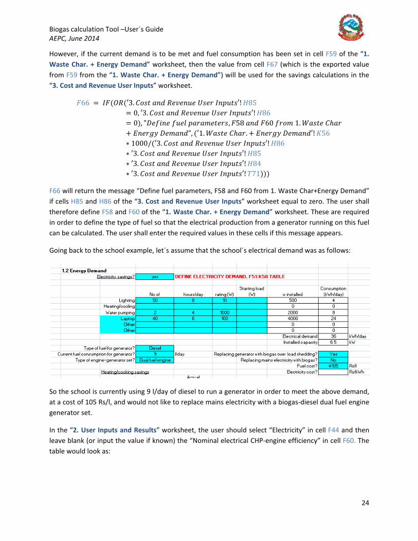
However, if the current demand is to be met and fuel consumption has been set in cell F59 of the “1. Waste Char. + Energy Demand” worksheet, then the value from cell F67 (which is the exported value from F59 from the “1. Waste Char. + Energy Demand”) will be used for the savings calculations in the “3. Cost and Revenue User Inputs” worksheet.
𝐹𝐹66 = 𝐼𝐼𝐹𝐹(𝑂𝑂𝑂𝑂(′3. 𝐶𝐶𝐵𝐵𝐵𝐵𝑤𝑤 𝐵𝐵𝑛𝑛𝑦𝑦 𝑂𝑂𝑦𝑦𝑅𝑅𝑦𝑦𝑛𝑛𝑛𝑛𝑦𝑦 𝑈𝑈𝐵𝐵𝑦𝑦𝑛𝑛 𝐼𝐼𝑛𝑛𝑝𝑝𝑛𝑛𝑤𝑤𝐵𝐵′! 𝐻𝐻85= 0, ′3. 𝐶𝐶𝐵𝐵𝐵𝐵𝑤𝑤 𝐵𝐵𝑛𝑛𝑦𝑦 𝑂𝑂𝑦𝑦𝑅𝑅𝑦𝑦𝑛𝑛𝑛𝑛𝑦𝑦 𝑈𝑈𝐵𝐵𝑦𝑦𝑛𝑛 𝐼𝐼𝑛𝑛𝑝𝑝𝑛𝑛𝑤𝑤𝐵𝐵′! 𝐻𝐻86= 0), "𝐴𝐴𝑦𝑦𝑜𝑜𝐵𝐵𝑛𝑛𝑦𝑦 𝑜𝑜𝑛𝑛𝑦𝑦𝑦𝑦 𝑝𝑝𝐵𝐵𝑛𝑛𝐵𝐵𝑚𝑚𝑦𝑦𝑤𝑤𝑦𝑦𝑛𝑛𝐵𝐵, 𝐹𝐹58 𝐵𝐵𝑛𝑛𝑦𝑦 𝐹𝐹60 𝑜𝑜𝑛𝑛𝐵𝐵𝑚𝑚 1. 𝐷𝐷𝐵𝐵𝐵𝐵𝑤𝑤𝑦𝑦 𝐶𝐶ℎ𝐵𝐵𝑛𝑛+ 𝐷𝐷𝑛𝑛𝑦𝑦𝑛𝑛𝐵𝐵𝑦𝑦 𝐴𝐴𝑦𝑦𝑚𝑚𝐵𝐵𝑛𝑛𝑦𝑦", (′1. 𝐷𝐷𝐵𝐵𝐵𝐵𝑤𝑤𝑦𝑦 𝐶𝐶ℎ𝐵𝐵𝑛𝑛. + 𝐷𝐷𝑛𝑛𝑦𝑦𝑛𝑛𝐵𝐵𝑦𝑦 𝐴𝐴𝑦𝑦𝑚𝑚𝐵𝐵𝑛𝑛𝑦𝑦′! 𝐾𝐾56∗ 1000/(′3. 𝐶𝐶𝐵𝐵𝐵𝐵𝑤𝑤 𝐵𝐵𝑛𝑛𝑦𝑦 𝑂𝑂𝑦𝑦𝑅𝑅𝑦𝑦𝑛𝑛𝑛𝑛𝑦𝑦 𝑈𝑈𝐵𝐵𝑦𝑦𝑛𝑛 𝐼𝐼𝑛𝑛𝑝𝑝𝑛𝑛𝑤𝑤𝐵𝐵′! 𝐻𝐻86∗ ′3. 𝐶𝐶𝐵𝐵𝐵𝐵𝑤𝑤 𝐵𝐵𝑛𝑛𝑦𝑦 𝑂𝑂𝑦𝑦𝑅𝑅𝑦𝑦𝑛𝑛𝑛𝑛𝑦𝑦 𝑈𝑈𝐵𝐵𝑦𝑦𝑛𝑛 𝐼𝐼𝑛𝑛𝑝𝑝𝑛𝑛𝑤𝑤𝐵𝐵′! 𝐻𝐻85∗ ′3. 𝐶𝐶𝐵𝐵𝐵𝐵𝑤𝑤 𝐵𝐵𝑛𝑛𝑦𝑦 𝑂𝑂𝑦𝑦𝑅𝑅𝑦𝑦𝑛𝑛𝑛𝑛𝑦𝑦 𝑈𝑈𝐵𝐵𝑦𝑦𝑛𝑛 𝐼𝐼𝑛𝑛𝑝𝑝𝑛𝑛𝑤𝑤𝐵𝐵′! 𝐻𝐻84∗ ′3. 𝐶𝐶𝐵𝐵𝐵𝐵𝑤𝑤 𝐵𝐵𝑛𝑛𝑦𝑦 𝑂𝑂𝑦𝑦𝑅𝑅𝑦𝑦𝑛𝑛𝑛𝑛𝑦𝑦 𝑈𝑈𝐵𝐵𝑦𝑦𝑛𝑛 𝐼𝐼𝑛𝑛𝑝𝑝𝑛𝑛𝑤𝑤𝐵𝐵′! 𝑇𝑇71)))
F66 will return the message “Define fuel parameters, F58 and F60 from 1. Waste Char+Energy Demand” if cells H85 and H86 of the “3. Cost and Revenue User Inputs” worksheet equal to zero. The user shall therefore define F58 and F60 of the “1. Waste Char. + Energy Demand” worksheet. These are required in order to define the type of fuel so that the electrical production from a generator running on this fuel can be calculated. The user shall enter the required values in these cells if this message appears.
Going back to the school example, let´s assume that the school´s electrical demand was as follows:
So the school is currently using 9 l/day of diesel to run a generator in order to meet the above demand, at a cost of 105 Rs/l, and would not like to replace mains electricity with a biogas-diesel dual fuel engine generator set.
In the “2. User Inputs and Results” worksheet, the user should select “Electricity” in cell F44 and then leave blank (or input the value if known) the “Nominal electrical CHP-engine efficiency” in cell F60. The table would look as:
Biogas calculation Tool –User´s Guide AEPC, June 2014
25
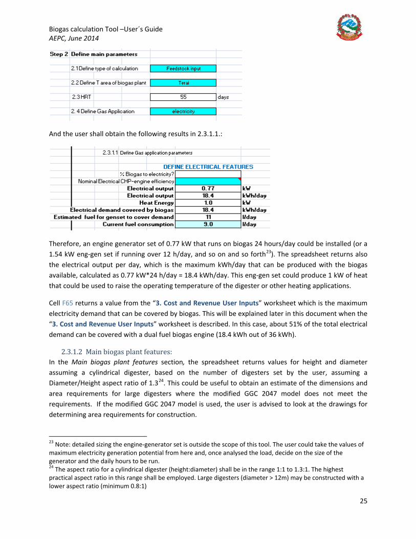
And the user shall obtain the following results in 2.3.1.1.:
Therefore, an engine generator set of 0.77 kW that runs on biogas 24 hours/day could be installed (or a 1.54 kW eng-gen set if running over 12 h/day, and so on and so forth23
2.3.1.2 Main biogas plant features:
). The spreadsheet returns also the electrical output per day, which is the maximum kWh/day that can be produced with the biogas available, calculated as 0.77 kW*24 h/day = 18.4 kWh/day. This eng-gen set could produce 1 kW of heat that could be used to raise the operating temperature of the digester or other heating applications.
Cell F65 returns a value from the “3. Cost and Revenue User Inputs” worksheet which is the maximum electricity demand that can be covered by biogas. This will be explained later in this document when the “3. Cost and Revenue User Inputs” worksheet is described. In this case, about 51% of the total electrical demand can be covered with a dual fuel biogas engine (18.4 kWh out of 36 kWh).
In the Main biogas plant features section, the spreadsheet returns values for height and diameter assuming a cylindrical digester, based on the number of digesters set by the user, assuming a Diameter/Height aspect ratio of 1.324
23 Note: detailed sizing the engine-generator set is outside the scope of this tool. The user could take the values of maximum electricity generation potential from here and, once analysed the load, decide on the size of the generator and the daily hours to be run. 24 The aspect ratio for a cylindrical digester (height:diameter) shall be in the range 1:1 to 1.3:1. The highest practical aspect ratio in this range shall be employed. Large digesters (diameter > 12m) may be constructed with a lower aspect ratio (minimum 0.8:1)
. This could be useful to obtain an estimate of the dimensions and area requirements for large digesters where the modified GGC 2047 model does not meet the requirements. If the modified GGC 2047 model is used, the user is advised to look at the drawings for determining area requirements for construction.
Biogas calculation Tool –User´s Guide AEPC, June 2014
26
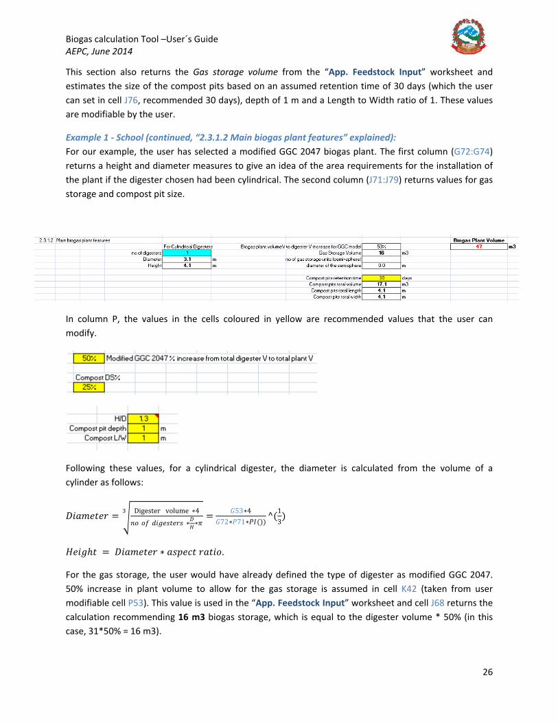
This section also returns the Gas storage volume from the “App. Feedstock Input” worksheet and estimates the size of the compost pits based on an assumed retention time of 30 days (which the user can set in cell J76, recommended 30 days), depth of 1 m and a Length to Width ratio of 1. These values are modifiable by the user.
Example 1 - School (continued, “2.3.1.2 Main biogas plant features” explained): For our example, the user has selected a modified GGC 2047 biogas plant. The first column (G72:G74) returns a height and diameter measures to give an idea of the area requirements for the installation of the plant if the digester chosen had been cylindrical. The second column (J71:J79) returns values for gas storage and compost pit size.
In column P, the values in the cells coloured in yellow are recommended values that the user can modify.
Following these values, for a cylindrical digester, the diameter is calculated from the volume of a cylinder as follows:
𝐴𝐴𝐵𝐵𝐵𝐵𝑚𝑚𝑦𝑦𝑤𝑤𝑦𝑦𝑛𝑛 = �Digester volume ∗4
𝑛𝑛𝐵𝐵 𝐵𝐵𝑜𝑜 𝑦𝑦𝐵𝐵𝐵𝐵𝑦𝑦𝐵𝐵𝑤𝑤𝑦𝑦𝑛𝑛𝐵𝐵 ∗𝐴𝐴𝐻𝐻∗𝜋𝜋
3 = 𝐺𝐺53∗4𝐺𝐺72∗𝑃𝑃71∗𝑃𝑃𝐼𝐼())
^(13)
𝐻𝐻𝑦𝑦𝐵𝐵𝐵𝐵ℎ𝑤𝑤 = 𝐴𝐴𝐵𝐵𝐵𝐵𝑚𝑚𝑦𝑦𝑤𝑤𝑦𝑦𝑛𝑛 ∗ 𝐵𝐵𝐵𝐵𝑝𝑝𝑦𝑦𝑖𝑖𝑤𝑤 𝑛𝑛𝐵𝐵𝑤𝑤𝐵𝐵𝐵𝐵.
For the gas storage, the user would have already defined the type of digester as modified GGC 2047. 50% increase in plant volume to allow for the gas storage is assumed in cell K42 (taken from user modifiable cell P53). This value is used in the “App. Feedstock Input” worksheet and cell J68 returns the calculation recommending 16 m3 biogas storage, which is equal to the digester volume * 50% (in this case, 31*50% = 16 m3).

Biogas calculation Tool –User´s Guide AEPC, June 2014
27
Let´s now look at the alternative of a cylindrical digester where 12 hours gas storage would have been chosen. In section 2, therefore:
The gas storage volume calculation takes place in the “App. Feedstock Input” worksheet, and in this case it will multiply the gas production (11.1 m3/day) by the storage time (12 hours), giving 6 m3 storage in cell J72.
Cell J73 is coloured bright blue when the type of digester is “Other” in cell K38, indicating the user to enter the number of gas storage units that are required. The shape assumed for the gas storage unit is that of a semisphere, and this is done to provide an estimate of land requirements for external gas storage. There could be different shapes and configurations, the gas unit could be placed on top of the digester by adjusting aspect ratios and shapes, or a floating drum digester may be used. The semisphere shape is purely used for indicative purposes.
The size of the compost pits is also calculated indicatively for estimating land area requirements. The shape is assumed as a rectangle (Length/Width ratio can be modified by the user in cell P73, and the depth in cell P72, recommended L/W ratio of 1 and depth of 1 meter) and a retention time (which the user can modify in cell J76, recommended 30 days).

Biogas calculation Tool –User´s Guide AEPC, June 2014
28
FINANCIAL ASSESSMENT
3. “3. COST AND REVENUE USER INPUTS” WORKSHEET In this worksheet the user shall enter the costs to be incurred by the project, both capital and operational, and the potential revenue streams, including savings and sales, which are required to perform the Financial Analysis in the “4. Financial Analysis” worksheet.
The user shall reply with a “Yes” or a “No” to each cost or revenue source question. If the answer is “Yes”, cells related to that cost will be highlighted in bright blue to indicate the user that a unit cost or revenue (or total cost or revenue) needs to be entered.
In points 3.1.2, 3.1.3 and 3.2 below a section for “Other” type of equipment has been included where the user can specify cost or revenue sources other than those stated in the worksheet.
3.1 COSTS
3.1.1 Biogas plant cost: The user shall specify the cost of 1 no biogas plant excluding ancillaries and the number of biogas plants required. The total cost in cell K25 is calculated as the product of the 𝑖𝑖𝐵𝐵𝐵𝐵𝑤𝑤 𝐵𝐵𝑜𝑜 𝑤𝑤ℎ𝑦𝑦 𝑝𝑝𝑦𝑦𝐵𝐵𝑛𝑛𝑤𝑤 ∗ 𝑛𝑛𝑛𝑛𝑚𝑚𝑛𝑛𝑦𝑦𝑛𝑛 𝐵𝐵𝑜𝑜 𝑝𝑝𝑦𝑦𝐵𝐵𝑛𝑛𝑤𝑤𝐵𝐵. These costs shall include all labour, machinery, materials, gas storage equipment, and any other costs
3.1.2 Ancillary options: The user must specify all ancillary options from the list given and their costs. The pipe cost is calculated per meter of gas pipe in cell H34, which can be specified in cell J34.
3.1.3 O&M costs: The user shall enter all costs associated with the Operation and Maintenance of the plant. These costs shall be entered on a monthly basis.
3.2 REVENUE These costs are divided between the expenses avoided and the potential profit to be made by selling commodities.
3.2.1 Savings:
The user would have responded to the questions on which fuel or electricity consumption will be replaced in the “1. Waste Char. + Energy Demand” worksheet, and, therefore, avoided by using biogas.

Biogas calculation Tool –User´s Guide AEPC, June 2014
29
Also, in that worksheet, the user would have defined the actual consumption of fuel or electrical demand. The cells exporting values from “1. Waste Char. + Energy Demand” into the “3. Cost and Revenue User Inputs” are coloured light blue.
3.2.1.1 Biogas fuel savings: The spreadsheet calculates the potential, estimated quantity of fuel avoided by the use of biogas comparing the energy content of the fuel to be replaced and that of biogas, accounting for the daily biogas production, accounting for the calorific values, leaks and comparing the efficiencies of different biogas stoves/burners that recommended in the “1. Waste Char. + Energy Demand” worksheet (which the user can modify to suit the site conditions). The user would have also entered the actual quantity of fuel consumed per month in the “1. Waste Char. + Energy Demand” worksheet, so that the estimate can be compared with the actual figures (if unknown, the user would have left it blank and the spreadsheet will only consider the estimated values). The estimated fuel expenditure savings will calculate, based on the unit price of fuel and the minimum value of the estimate and the actual consumption, the monthly savings. This is illustrated in Example 2 – Cow Farm, below.
3.2.1.2 Electricity savings: Regarding electricity savings, the user would have completed the electricity demand table in the “1. Waste Char. + Energy Demand” worksheet, which will determine, comparing the kWh/day required with the kWh/day available from biogas production, how much, as a percentage, could be covered with biogas.
The user would have answered whether a generator is being replaced, and enter the actual fuel consumption of that generator per day25
The user would have also entered the cost of fuel to run the generator to be replaced by biogas, whether mains electricity may be replaced by biogas generated electricity in the “1. Waste Char. + Energy Demand”, and the spreadsheet will account for the biogas left over from replacing the diesel generator, estimate how much auxiliary fuel (in the form of diesel, etc., if any, depending on the type of engine, as per the user´s selection for the type of engine) is required for running the engine-generator set in a dual-fuel mode if this is the technology chosen, and compare the potential savings from running a biogas engine-generator during mains electricity hours to just buying electricity from the grid over that period. The spreadsheet will display, in H99, a message showing “DO NOT REPLACE MAINS ELECTRICITY
in the “1. Waste Char. + Energy Demand”. The “3. Cost and Revenue User Inputs” worksheet will export those values to the cells coloured light blue.
The spreadsheet then calculates how much of that fuel can be replaced by biogas, accounting for the fact that a % of that fuel may still be needed to run the engine-generator set in a dual fuel mode (if this is the case, which may not for an engine running 100% on biogas; the user would have made this decision in the “1. Waste Char. + Energy Demand” worksheet).
25The values in H85:H88 export values from the “1. Waste Char. + Energy Demand”, where the generator efficiency is exported from the “2. User Inputs and Results” worksheet. All of the above are user modifiable.
Biogas calculation Tool –User´s Guide AEPC, June 2014
30
WITH BIOGAS” or “REPLACE MAINS ELECTRICITY WITH BIOGAS”, depending on which option is more economical. In general, this may only be the case for engine-generator sets running on 100% biogas, though the capital cost of these engines may offset the benefits.
The total savings from replacing electricity with biogas (cell F100), accounts for the cases explained above, and only considers replacing mains electricity savings by a biogas generator when this is a viable option. This whole calculation is explained in Example 2 – Cow Farm, below.
3.2.2 Sales:
3.2.2.1 Biogas equivalent table: Table N59:O67 calculates the biogas equivalent m3 per day for each of the fuels and electricity replaced. It does this by performing the reverse calculation followed to estimate the fuel savings or electricity production in the “Savings” section above, and selects in O60, O62, O64 and O65 the minimum value out of the “actual” and the “estimated” consumptions to approximate the calculation to the real savings, to which the biogas required for lighting is added on N66. Where the “actual” consumption value is not known, this will be zero, but the spreadsheet will then consider the “estimated value” based on the biogas available.
This table calculates the total biogas used to replace current used fuels and/or electricity (cell N67), and then compares it to the total biogas available N68 (which is the Total Biogas Production (2. User Inputs and Results'!G54)*Gas utilization (App. Feedstock Input L86, assumed 90%).
Cell N69 determines whether the user can cover all the demand from the biogas available by comparing the above values and displays the message OK, when this is possible, or BIOGAS USAGE CANNOT BE MORE THAN BIOGAS AVAILABLE, when this is not possible. In the latter case, the user shall go back to the “1. Waste Char. + Energy Demand” worksheet and reduce the actual consumption of fuel or the electricity demand table to lower the biogas consumption requirements.
Cell N70 calculates the biogas that can be sold either as biogas or electricity by subtracting the biogas used from the biogas available.
The illustration of all of the above is explained in detail in the examples below.
3.2.2.2 Biogas sales: The project could sell biogas to other nearby households or industries. The spreadsheet proposes two revenue models: one in which the owner charges “per m3 of biogas”, and another one in which the owner charges a “monthly fee”. There is also the option of charging for an entry tariff, which is calculated per year. The user shall select between the two models and then fill in the cells coloured bright blue. The user shall select, as a % of all the biogas available for sales, how much will be sold as biogas. Final biogas revenue is calculated per month.
3.2.2.3 Electricity sales: The same principle applies to electricity sales as per biogas sales, with the only difference that the % is calculated as whatever is left from the biogas sales and one of the payment methods is per kWh.
Biogas calculation Tool –User´s Guide AEPC, June 2014
31
3.2.2.4 Fertilizer sales: Fertilizer revenues are calculated from the estimated compost production and a fertilizer unit cost that the user shall enter.
The total revenue (cell L107) is calculated as the sum of all the monthly savings plus the sum of all the monthly revenues:
𝑇𝑇𝐵𝐵𝑤𝑤𝐵𝐵𝑦𝑦 𝑛𝑛𝑦𝑦𝑅𝑅𝑦𝑦𝑛𝑛𝑛𝑛𝑦𝑦 = 𝑉𝑉𝑈𝑈𝑀𝑀(𝐹𝐹63, 𝐹𝐹70, 𝐹𝐹77, 𝐹𝐹106, 𝐹𝐹100) + 𝑉𝑉𝑈𝑈𝑀𝑀(𝑁𝑁78, 𝑁𝑁90, 𝑁𝑁95, 𝑁𝑁101) + (𝑁𝑁89 +𝑁𝑁77)/12).
This does consider the one-off entry tariffs for electricity and biogas, N89 and N77 adjusting for per month basis.
3.3 SUBSIDY The subsidy delivered by AEPC depends on two aspects: the type of organization where the plant is installed and the gas application. The subsidy is provided depending on the size of the plant (per m3), including gas storage volume, based on the modified GGC 2047 model, and on whether electricity is produced or not, for which subsidy is provided per kW installed capacity, for the case in which an engine-generator set was installed that run over 24 hours consuming all biogas produced daily26
Example 1- School (continued, “3. Cost and Revenue User Inputs” worksheet explained for cooking purposes):
).
The user shall then decide on the type of biogas project among “Commercial”, “Institutional”, “Community” or “Waste to Energy (W2E)”, and the worksheet will calculate how much subsidy will be provided, which will later on be used in the “4. Financial Analysis” worksheet.
Let´s see the “3. Cost and Revenue User Inputs” at work in our school and cow farm examples.
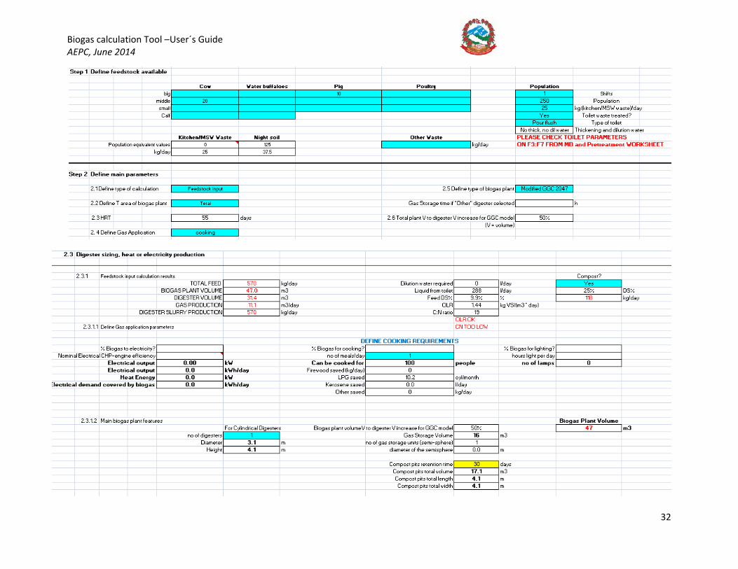
Let´s have a look at what the “2. User Inputs and Results” worksheet looked like for our school´s principal.
26 This means that if a generator needs to be twice the size of this, i.e., consuming the energy from biogas in 12 hours, the user shall not get twice the amount of subsidy, but that corresponding to a generator rated to run over 24 hours (in this case, half of what would be required if the load profile calls for a generator to run 12h/day. This is to avoid oversizing of generators and keep a consistent subsidy delivery policy)
Biogas calculation Tool –User´s Guide AEPC, June 2014
32

Biogas calculation Tool –User´s Guide AEPC, June 2014
33
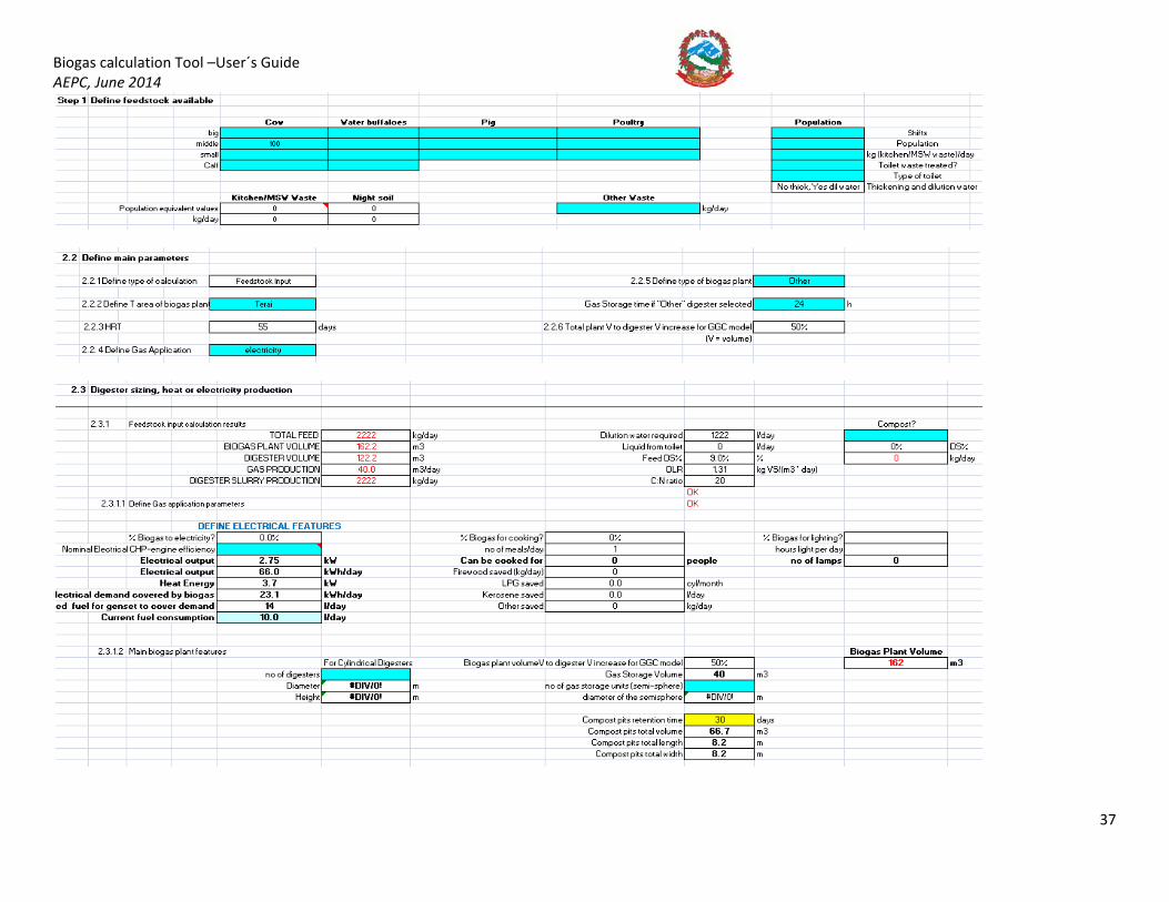
So the Biogas plant volume would be 47 m3, digester slurry production 570 kg/day, compost production 118 kg/day, biogas production of 11.1 m3/day, which is enough to cook 1 meal for 100 out of the 250 students and staff of the school. Looking at the “3. Cost and Revenue User Inputs” worksheet now:
3.1 COSTS 3.1.1 Biogas Plant Cost
The plant to be installed would be, based on a 47 m3 volume, a 50 m3 biogas plant. The total cost for such a plant would be approximately 570,000 Rs (assumed), and that only 1 no biogas plant of that size will be built
Cell K25, Total biogas plant cost, is calculated by multiplying the number of digesters by the cost of an individual digester. K25=H23*G24.
3.1.2 Ancillary Options The plant does not need any pre-processing equipment other than a grinder for the kitchen waste, which comes at a cost of 3,000 Rs (assumed). As the digester feed DS% are above 6% (precondition set in the “App. MB and Pretreatment” worksheet for not requiring a thickening unit upstream, or changing the system to a DEWATS plant, or other – as detailed in Appendix A), there is no requirement for a thickening tank or need for other alternatives such as DEWATS. The plant can treat the toilet waste incoming. No pumps, heating, or mixing (other than the manual handle in the feed chamber, included as part of the total biogas plant cost in 1.1 above) are provided. The kitchen is 40 m away from the biogas plant, so 40 m of biogas pipe (at 500 Rs/m) need to be installed (H34 =J34*F34); as no electricity is produced then no biogas conditioning unit or engine-generator set are required; valves and instrumentation (pressure meters and gas valves) will amount to 5,000 Rs (assumed); and it is assumed that the pressure generated in the biogas plant is enough to reach the kitchen, so no compressor is required. The Total Ancillary Cost, K41 =SUM(H30:H39). Section 1.2 Ancillary Options will look as follows in the spreadsheet:

Biogas calculation Tool –User´s Guide AEPC, June 2014
34
3.1.3 O&M costs The school will use, as seen from the results of the “App. MB and Pretreatment” worksheet, the water and urine from the toilets to dilute the feed to the digester, therefore not requiring extra dilution water. Substrate will be collected on site by the school guard so no extra costs are incurred into. The students will be operating the plant as part of a teaching programme from the school, so no labour costs are considered, and gas and electricity costs are not applicable (no compressor required for biogas, no electricity transmitted). Maintenance is assumed to be 500 Rs/month to compensate for repairs, etc. The Total O&M cost, K46=SUM(H46:H53). The table will look as follows:
3.2 REVENUE 3.2.1 Savings:
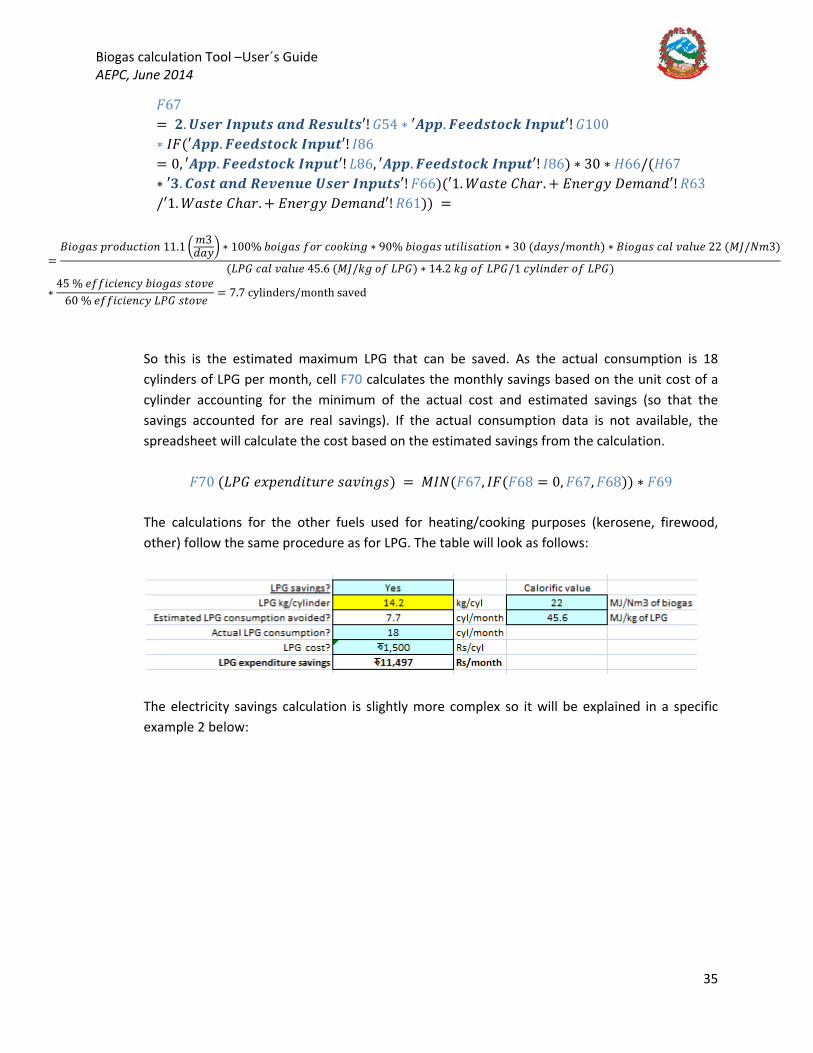
The school will be replacing LPG gas that is currently used for cooking. The user inputs “Yes” in cell F65 and cells F68, Actual LPG consumption, and F69, LPG cost, are highlighted in blue. The school principal states that they use 18 cylinders of LPG per month to cook for all the students and staff. The cost of an LPG cylinder is 1500 Rs entered in cell F69. Cell F67 calculates the estimated LPG consumption avoided based on the calorific values and the biogas production as follows27
27 References to the “Demand and App. Feedstock Input” worksheet and calculation for the cells have been removed for clarity purposes.
:
Biogas calculation Tool –User´s Guide AEPC, June 2014
35
𝐹𝐹67 = 𝟐𝟐. 𝑼𝑼𝑭𝑭𝑭𝑭𝑼𝑼 𝑰𝑰𝑰𝑰𝑨𝑨𝑰𝑰𝑭𝑭𝑭𝑭 𝒂𝒂𝑰𝑰𝑭𝑭 𝑹𝑹𝑭𝑭𝑭𝑭𝑰𝑰𝑹𝑹𝑭𝑭𝑭𝑭′! 𝐺𝐺54 ∗ ′𝑨𝑨𝑨𝑨𝑨𝑨. 𝑭𝑭𝑭𝑭𝑭𝑭𝑭𝑭𝑭𝑭𝑭𝑭𝑭𝑭𝑭𝑭𝑭𝑭 𝑰𝑰𝑰𝑰𝑨𝑨𝑰𝑰𝑭𝑭′! 𝐺𝐺100∗ 𝐼𝐼𝐹𝐹(′𝑨𝑨𝑨𝑨𝑨𝑨. 𝑭𝑭𝑭𝑭𝑭𝑭𝑭𝑭𝑭𝑭𝑭𝑭𝑭𝑭𝑭𝑭𝑭𝑭 𝑰𝑰𝑰𝑰𝑨𝑨𝑰𝑰𝑭𝑭′! 𝐼𝐼86= 0, ′𝑨𝑨𝑨𝑨𝑨𝑨. 𝑭𝑭𝑭𝑭𝑭𝑭𝑭𝑭𝑭𝑭𝑭𝑭𝑭𝑭𝑭𝑭𝑭𝑭 𝑰𝑰𝑰𝑰𝑨𝑨𝑰𝑰𝑭𝑭′! 𝐿𝐿86, ′𝑨𝑨𝑨𝑨𝑨𝑨. 𝑭𝑭𝑭𝑭𝑭𝑭𝑭𝑭𝑭𝑭𝑭𝑭𝑭𝑭𝑭𝑭𝑭𝑭 𝑰𝑰𝑰𝑰𝑨𝑨𝑰𝑰𝑭𝑭′! 𝐼𝐼86) ∗ 30 ∗ 𝐻𝐻66/(𝐻𝐻67∗ ′𝟑𝟑. 𝑪𝑪𝑭𝑭𝑭𝑭𝑭𝑭 𝒂𝒂𝑰𝑰𝑭𝑭 𝑹𝑹𝑭𝑭𝑹𝑹𝑭𝑭𝑰𝑰𝑰𝑰𝑭𝑭 𝑼𝑼𝑭𝑭𝑭𝑭𝑼𝑼 𝑰𝑰𝑰𝑰𝑨𝑨𝑰𝑰𝑭𝑭𝑭𝑭′! 𝐹𝐹66)(′1. 𝐷𝐷𝐵𝐵𝐵𝐵𝑤𝑤𝑦𝑦 𝐶𝐶ℎ𝐵𝐵𝑛𝑛. + 𝐷𝐷𝑛𝑛𝑦𝑦𝑛𝑛𝐵𝐵𝑦𝑦 𝐴𝐴𝑦𝑦𝑚𝑚𝐵𝐵𝑛𝑛𝑦𝑦′! 𝑂𝑂63/′1. 𝐷𝐷𝐵𝐵𝐵𝐵𝑤𝑤𝑦𝑦 𝐶𝐶ℎ𝐵𝐵𝑛𝑛. + 𝐷𝐷𝑛𝑛𝑦𝑦𝑛𝑛𝐵𝐵𝑦𝑦 𝐴𝐴𝑦𝑦𝑚𝑚𝐵𝐵𝑛𝑛𝑦𝑦′! 𝑂𝑂61)) =
=𝐵𝐵𝐵𝐵𝐵𝐵𝐵𝐵𝐵𝐵𝐵𝐵 𝑝𝑝𝑛𝑛𝐵𝐵𝑦𝑦𝑛𝑛𝑖𝑖𝑤𝑤𝐵𝐵𝐵𝐵𝑛𝑛 11.1 � 𝑚𝑚3
𝑦𝑦𝐵𝐵𝑦𝑦� ∗ 100% 𝑛𝑛𝐵𝐵𝐵𝐵𝐵𝐵𝐵𝐵𝐵𝐵 𝑜𝑜𝐵𝐵𝑛𝑛 𝑖𝑖𝐵𝐵𝐵𝐵𝑘𝑘𝐵𝐵𝑛𝑛𝐵𝐵 ∗ 90% 𝑛𝑛𝐵𝐵𝐵𝐵𝐵𝐵𝐵𝐵𝐵𝐵 𝑛𝑛𝑤𝑤𝐵𝐵𝑦𝑦𝐵𝐵𝐵𝐵𝐵𝐵𝑤𝑤𝐵𝐵𝐵𝐵𝑛𝑛 ∗ 30 (𝑦𝑦𝐵𝐵𝑦𝑦𝐵𝐵/𝑚𝑚𝐵𝐵𝑛𝑛𝑤𝑤ℎ) ∗ 𝐵𝐵𝐵𝐵𝐵𝐵𝐵𝐵𝐵𝐵𝐵𝐵 𝑖𝑖𝐵𝐵𝑦𝑦 𝑅𝑅𝐵𝐵𝑦𝑦𝑛𝑛𝑦𝑦 22 (𝑀𝑀𝑀𝑀/𝑁𝑁𝑚𝑚3)
(𝐿𝐿𝑃𝑃𝐺𝐺 𝑖𝑖𝐵𝐵𝑦𝑦 𝑅𝑅𝐵𝐵𝑦𝑦𝑛𝑛𝑦𝑦 45.6 (𝑀𝑀𝑀𝑀/𝑘𝑘𝐵𝐵 𝐵𝐵𝑜𝑜 𝐿𝐿𝑃𝑃𝐺𝐺) ∗ 14.2 𝑘𝑘𝐵𝐵 𝐵𝐵𝑜𝑜 𝐿𝐿𝑃𝑃𝐺𝐺/1 𝑖𝑖𝑦𝑦𝑦𝑦𝐵𝐵𝑛𝑛𝑦𝑦𝑦𝑦𝑛𝑛 𝐵𝐵𝑜𝑜 𝐿𝐿𝑃𝑃𝐺𝐺)
∗45 % 𝑦𝑦𝑜𝑜𝑜𝑜𝐵𝐵𝑖𝑖𝐵𝐵𝑦𝑦𝑛𝑛𝑖𝑖𝑦𝑦 𝑛𝑛𝐵𝐵𝐵𝐵𝐵𝐵𝐵𝐵𝐵𝐵 𝐵𝐵𝑤𝑤𝐵𝐵𝑅𝑅𝑦𝑦
60 % 𝑦𝑦𝑜𝑜𝑜𝑜𝐵𝐵𝑖𝑖𝐵𝐵𝑦𝑦𝑛𝑛𝑖𝑖𝑦𝑦 𝐿𝐿𝑃𝑃𝐺𝐺 𝐵𝐵𝑤𝑤𝐵𝐵𝑅𝑅𝑦𝑦 = 7.7 cylinders/month saved
So this is the estimated maximum LPG that can be saved. As the actual consumption is 18 cylinders of LPG per month, cell F70 calculates the monthly savings based on the unit cost of a cylinder accounting for the minimum of the actual cost and estimated savings (so that the savings accounted for are real savings). If the actual consumption data is not available, the spreadsheet will calculate the cost based on the estimated savings from the calculation.
𝐹𝐹70 (𝐿𝐿𝑃𝑃𝐺𝐺 𝑦𝑦𝑒𝑒𝑝𝑝𝑦𝑦𝑛𝑛𝑦𝑦𝐵𝐵𝑤𝑤𝑛𝑛𝑛𝑛𝑦𝑦 𝐵𝐵𝐵𝐵𝑅𝑅𝐵𝐵𝑛𝑛𝐵𝐵𝐵𝐵) = 𝑀𝑀𝐼𝐼𝑁𝑁(𝐹𝐹67, 𝐼𝐼𝐹𝐹(𝐹𝐹68 = 0, 𝐹𝐹67, 𝐹𝐹68)) ∗ 𝐹𝐹69 The calculations for the other fuels used for heating/cooking purposes (kerosene, firewood, other) follow the same procedure as for LPG. The table will look as follows:
The electricity savings calculation is slightly more complex so it will be explained in a specific example 2 below:
Biogas calculation Tool –User´s Guide AEPC, June 2014
36
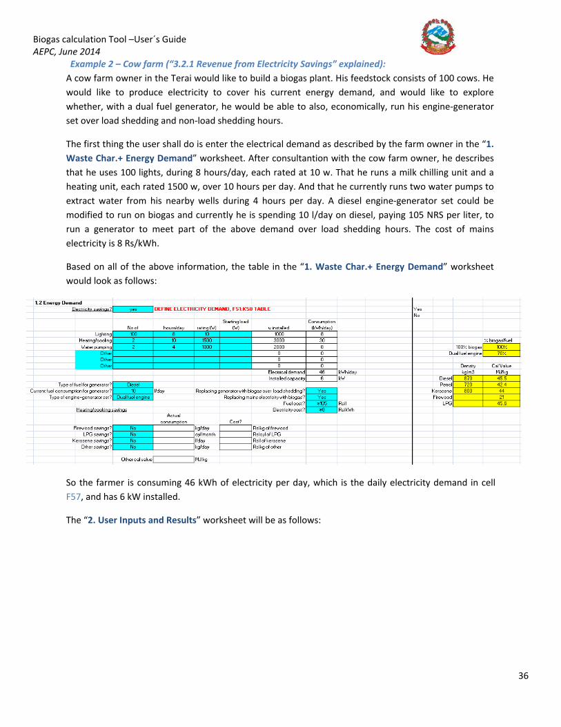
Example 2 – Cow farm (“3.2.1 Revenue from Electricity Savings” explained): A cow farm owner in the Terai would like to build a biogas plant. His feedstock consists of 100 cows. He would like to produce electricity to cover his current energy demand, and would like to explore whether, with a dual fuel generator, he would be able to also, economically, run his engine-generator set over load shedding and non-load shedding hours.
The first thing the user shall do is enter the electrical demand as described by the farm owner in the “1. Waste Char.+ Energy Demand” worksheet. After consultantion with the cow farm owner, he describes that he uses 100 lights, during 8 hours/day, each rated at 10 w. That he runs a milk chilling unit and a heating unit, each rated 1500 w, over 10 hours per day. And that he currently runs two water pumps to extract water from his nearby wells during 4 hours per day. A diesel engine-generator set could be modified to run on biogas and currently he is spending 10 l/day on diesel, paying 105 NRS per liter, to run a generator to meet part of the above demand over load shedding hours. The cost of mains electricity is 8 Rs/kWh.
Based on all of the above information, the table in the “1. Waste Char.+ Energy Demand” worksheet would look as follows:
So the farmer is consuming 46 kWh of electricity per day, which is the daily electricity demand in cell F57, and has 6 kW installed.
The “2. User Inputs and Results” worksheet will be as follows:
Biogas calculation Tool –User´s Guide AEPC, June 2014
37

Biogas calculation Tool –User´s Guide AEPC, June 2014
38
In the “3. Cost and Revenue User Inputs” worksheet, the first thing the user shall do is to define the costs of the plant. Let´s assume that the 162 m3 biogas plant (including storage) is 1,500,000 Rs. Ancillary costs are as described in the table below, O&M costs are 1000 Rs/month to transport fertilizer to the market, 12,000 Rs/month to pay an operator dedicated to the biogas plant, and 1,000 Rs/month for maintenance28
For the electricity savings, the electricity demand table is imported to table S76:Y84, and the values for electricity demand taken from there to the electricity savings table (such as in F80). The maximum electrical output from the biogas available (from the “2. User Input and Results” worksheet G54 is 40 m3/day*90% to account for leaks, etc) is given in F81, which is 66 kWh per day. These calculations take place in the “App. Feedstock Input” worksheet and are detailed in Appendix A. That is the result shown in cell F81. F82 calculates the % that can be covered from biogas out of the total demand. As 66 kWh>46 kWh, the biogas available could cover all the demand required (𝐹𝐹82 = 𝐼𝐼𝐹𝐹(𝐹𝐹80 = 0,0, 𝐼𝐼𝐹𝐹(𝐹𝐹81/𝐹𝐹80 >100%, 100%, 𝐹𝐹81/𝐹𝐹80)). The first section of the table will look as follows:
. The costs will be as follows:
Biogas electrical production shall be prioritized to meet load shedding hours, as generator electricity is more expensive than mains electricity.
28 The user shall find these out from the assessment done at the feasibility study stage.

Biogas calculation Tool –User´s Guide AEPC, June 2014
39
Fuel consumption in F84 is imported from the “1. Waste Char.+ Energy Demand” worksheet. Based on this, cell F85 estimates the amount of electrical energy produced by the generator as follows:
𝐷𝐷𝐵𝐵𝑤𝑤𝐵𝐵𝑚𝑚𝐵𝐵𝑤𝑤𝑦𝑦𝑦𝑦 𝐵𝐵𝑦𝑦𝑛𝑛𝑦𝑦𝑛𝑛𝐵𝐵𝑤𝑤𝐵𝐵𝑛𝑛 𝑦𝑦𝑦𝑦𝑦𝑦𝑖𝑖𝑤𝑤𝑛𝑛𝐵𝐵𝑖𝑖𝐵𝐵𝑤𝑤𝑦𝑦 𝑝𝑝𝑛𝑛𝐵𝐵𝑦𝑦𝑛𝑛𝑖𝑖𝑦𝑦𝑦𝑦
= 𝑜𝑜𝑛𝑛𝑦𝑦𝑦𝑦 𝑖𝑖𝐵𝐵𝑛𝑛𝐵𝐵𝑛𝑛𝑚𝑚𝑝𝑝𝑤𝑤𝐵𝐵𝐵𝐵𝑛𝑛 � 𝑦𝑦
𝑦𝑦𝐵𝐵𝑦𝑦� ∗ 𝑦𝑦𝑦𝑦𝑛𝑛𝐵𝐵𝐵𝐵𝑤𝑤𝑦𝑦 �𝑘𝑘𝐵𝐵𝑚𝑚3� ∗ 𝑦𝑦𝑜𝑜𝑜𝑜𝐵𝐵𝑖𝑖𝐵𝐵𝑦𝑦𝑛𝑛𝑖𝑖𝑦𝑦% ∗ 𝑖𝑖𝐵𝐵𝑦𝑦 𝑅𝑅𝐵𝐵𝑦𝑦𝑛𝑛𝑦𝑦 �𝑀𝑀𝑀𝑀
𝑘𝑘𝐵𝐵� ∗ 0.278(𝑘𝑘𝐷𝐷ℎ𝑀𝑀𝑀𝑀 )
1000 � 𝑦𝑦𝑚𝑚3�
= F84 ∗ H86 ∗ H84 ∗ H85/1000
This is how the table looks like now:
Table H84:H88 imports the values for the fuel and engine parameters from the “1. Waste Char.+Energy demand” worksheet and the “2. User Inputs and Results” worksheet. In our case, diesel is used:
Cell F86 calculates how much of the total generator produced electricity can be covered by biogas by comparing the biogas electrical energy available F81 to the electricity produced currently by the generator F85, using the following formula:
𝐹𝐹86 = 𝐼𝐼𝐹𝐹(𝐹𝐹85 = 0,0, 𝐼𝐼𝐹𝐹(𝐹𝐹81/𝐹𝐹85 > 100%, 100%, 𝐹𝐹81/𝐹𝐹85)).
However, cell F87, Actual % covered by biogas, will take the minimum of F86 and H87 (H87 provides an estimate of how much fuel can be replaced by biogas in a dual fuel engine, as both are required for the engine to work; recommended 70%, though the user can modify in the “1. Waste Char.+ Energy Demand” worksheet).
F88 calculates, based on the % of fuel that can be replaced, the amount of biogas energy that is required for this purpose as:
𝐹𝐹88 = 𝐹𝐹85 ∗ 𝐹𝐹87 = (𝑦𝑦𝐵𝐵𝑤𝑤𝐵𝐵𝑚𝑚𝐵𝐵𝑤𝑤𝑦𝑦𝑦𝑦 𝐵𝐵𝑦𝑦𝑛𝑛𝑦𝑦𝑛𝑛𝐵𝐵𝑤𝑤𝐵𝐵𝑛𝑛 𝑦𝑦𝑦𝑦𝑦𝑦𝑖𝑖𝑤𝑤𝑛𝑛𝐵𝐵𝑖𝑖𝐵𝐵𝑤𝑤𝑦𝑦 𝑝𝑝𝑛𝑛𝐵𝐵𝑦𝑦𝑛𝑛𝑖𝑖𝑦𝑦𝑦𝑦) ∗ (𝐵𝐵𝑖𝑖𝑤𝑤𝑛𝑛𝐵𝐵𝑦𝑦 % 𝑖𝑖𝐵𝐵𝑅𝑅𝑦𝑦𝑛𝑛𝑦𝑦𝑦𝑦 𝑛𝑛𝑦𝑦 𝑛𝑛𝐵𝐵𝐵𝐵𝐵𝐵𝐵𝐵𝐵𝐵).
F89 imports the value of the cost of fuel from the “1. Waste Char. + Energy Demand” worksheet. Cell F90 will then calculate how much can be saved by replacing the generator fuel with biogas as follows:
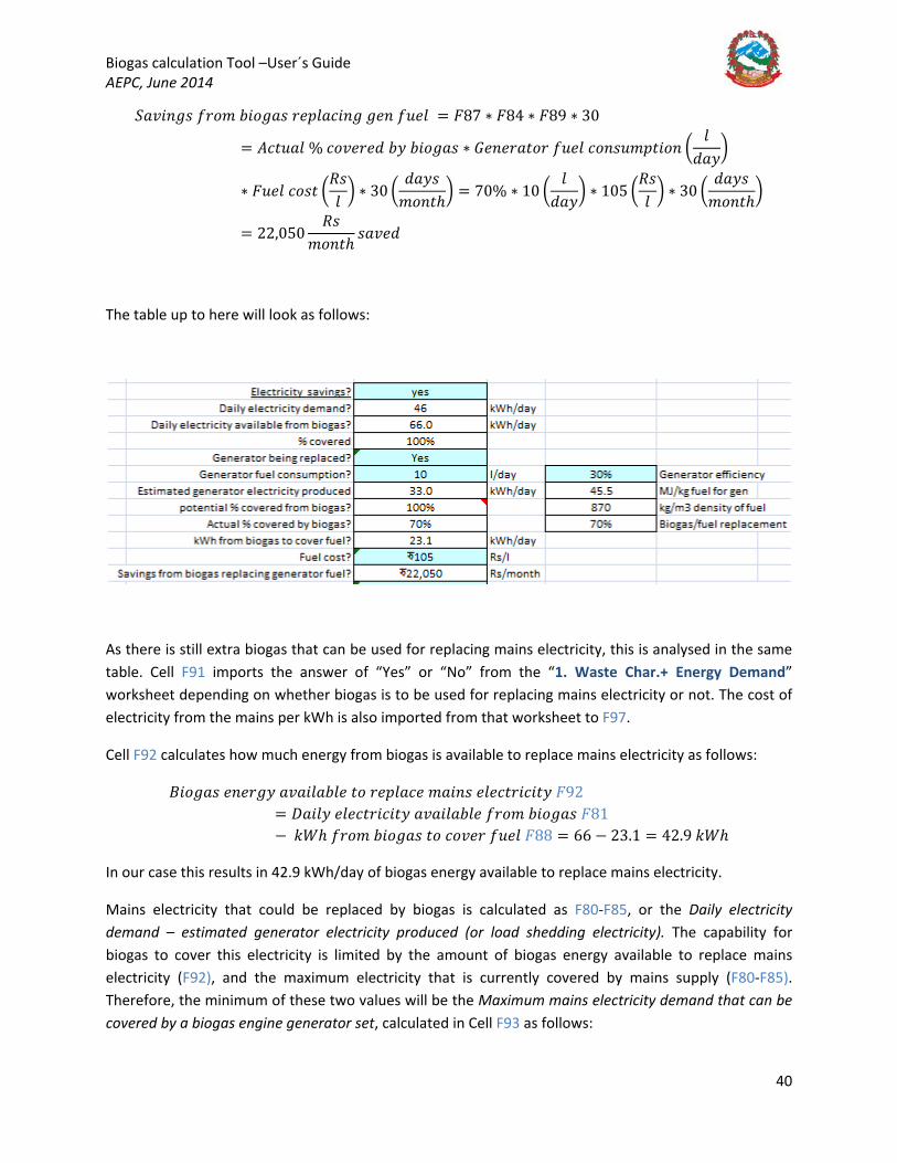
Biogas calculation Tool –User´s Guide AEPC, June 2014
40
𝑉𝑉𝐵𝐵𝑅𝑅𝐵𝐵𝑛𝑛𝐵𝐵𝐵𝐵 𝑜𝑜𝑛𝑛𝐵𝐵𝑚𝑚 𝑛𝑛𝐵𝐵𝐵𝐵𝐵𝐵𝐵𝐵𝐵𝐵 𝑛𝑛𝑦𝑦𝑝𝑝𝑦𝑦𝐵𝐵𝑖𝑖𝐵𝐵𝑛𝑛𝐵𝐵 𝐵𝐵𝑦𝑦𝑛𝑛 𝑜𝑜𝑛𝑛𝑦𝑦𝑦𝑦 = 𝐹𝐹87 ∗ 𝐹𝐹84 ∗ 𝐹𝐹89 ∗ 30
= 𝐴𝐴𝑖𝑖𝑤𝑤𝑛𝑛𝐵𝐵𝑦𝑦 % 𝑖𝑖𝐵𝐵𝑅𝑅𝑦𝑦𝑛𝑛𝑦𝑦𝑦𝑦 𝑛𝑛𝑦𝑦 𝑛𝑛𝐵𝐵𝐵𝐵𝐵𝐵𝐵𝐵𝐵𝐵 ∗ 𝐺𝐺𝑦𝑦𝑛𝑛𝑦𝑦𝑛𝑛𝐵𝐵𝑤𝑤𝐵𝐵𝑛𝑛 𝑜𝑜𝑛𝑛𝑦𝑦𝑦𝑦 𝑖𝑖𝐵𝐵𝑛𝑛𝐵𝐵𝑛𝑛𝑚𝑚𝑝𝑝𝑤𝑤𝐵𝐵𝐵𝐵𝑛𝑛 �𝑦𝑦
𝑦𝑦𝐵𝐵𝑦𝑦�
∗ 𝐹𝐹𝑛𝑛𝑦𝑦𝑦𝑦 𝑖𝑖𝐵𝐵𝐵𝐵𝑤𝑤 �𝑂𝑂𝐵𝐵𝑦𝑦
� ∗ 30 �𝑦𝑦𝐵𝐵𝑦𝑦𝐵𝐵
𝑚𝑚𝐵𝐵𝑛𝑛𝑤𝑤ℎ� = 70% ∗ 10 �
𝑦𝑦𝑦𝑦𝐵𝐵𝑦𝑦
� ∗ 105 �𝑂𝑂𝐵𝐵𝑦𝑦
� ∗ 30 �𝑦𝑦𝐵𝐵𝑦𝑦𝐵𝐵
𝑚𝑚𝐵𝐵𝑛𝑛𝑤𝑤ℎ�
= 22,050𝑂𝑂𝐵𝐵
𝑚𝑚𝐵𝐵𝑛𝑛𝑤𝑤ℎ𝐵𝐵𝐵𝐵𝑅𝑅𝑦𝑦𝑦𝑦
The table up to here will look as follows:
As there is still extra biogas that can be used for replacing mains electricity, this is analysed in the same table. Cell F91 imports the answer of “Yes” or “No” from the “1. Waste Char.+ Energy Demand” worksheet depending on whether biogas is to be used for replacing mains electricity or not. The cost of electricity from the mains per kWh is also imported from that worksheet to F97.
Cell F92 calculates how much energy from biogas is available to replace mains electricity as follows:
𝐵𝐵𝐵𝐵𝐵𝐵𝐵𝐵𝐵𝐵𝐵𝐵 𝑦𝑦𝑛𝑛𝑦𝑦𝑛𝑛𝐵𝐵𝑦𝑦 𝐵𝐵𝑅𝑅𝐵𝐵𝐵𝐵𝑦𝑦𝐵𝐵𝑛𝑛𝑦𝑦𝑦𝑦 𝑤𝑤𝐵𝐵 𝑛𝑛𝑦𝑦𝑝𝑝𝑦𝑦𝐵𝐵𝑖𝑖𝑦𝑦 𝑚𝑚𝐵𝐵𝐵𝐵𝑛𝑛𝐵𝐵 𝑦𝑦𝑦𝑦𝑦𝑦𝑖𝑖𝑤𝑤𝑛𝑛𝐵𝐵𝑖𝑖𝐵𝐵𝑤𝑤𝑦𝑦 𝐹𝐹92= 𝐴𝐴𝐵𝐵𝐵𝐵𝑦𝑦𝑦𝑦 𝑦𝑦𝑦𝑦𝑦𝑦𝑖𝑖𝑤𝑤𝑛𝑛𝐵𝐵𝑖𝑖𝐵𝐵𝑤𝑤𝑦𝑦 𝐵𝐵𝑅𝑅𝐵𝐵𝐵𝐵𝑦𝑦𝐵𝐵𝑛𝑛𝑦𝑦𝑦𝑦 𝑜𝑜𝑛𝑛𝐵𝐵𝑚𝑚 𝑛𝑛𝐵𝐵𝐵𝐵𝐵𝐵𝐵𝐵𝐵𝐵 𝐹𝐹81− 𝑘𝑘𝐷𝐷ℎ 𝑜𝑜𝑛𝑛𝐵𝐵𝑚𝑚 𝑛𝑛𝐵𝐵𝐵𝐵𝐵𝐵𝐵𝐵𝐵𝐵 𝑤𝑤𝐵𝐵 𝑖𝑖𝐵𝐵𝑅𝑅𝑦𝑦𝑛𝑛 𝑜𝑜𝑛𝑛𝑦𝑦𝑦𝑦 𝐹𝐹88 = 66 − 23.1 = 42.9 𝑘𝑘𝐷𝐷ℎ
In our case this results in 42.9 kWh/day of biogas energy available to replace mains electricity.
Mains electricity that could be replaced by biogas is calculated as F80-F85, or the Daily electricity demand – estimated generator electricity produced (or load shedding electricity). The capability for biogas to cover this electricity is limited by the amount of biogas energy available to replace mains electricity (F92), and the maximum electricity that is currently covered by mains supply (F80-F85). Therefore, the minimum of these two values will be the Maximum mains electricity demand that can be covered by a biogas engine generator set, calculated in Cell F93 as follows:

Biogas calculation Tool –User´s Guide AEPC, June 2014
41
𝐹𝐹93 = 𝑀𝑀𝐼𝐼𝑁𝑁 �𝐹𝐹92, �𝐼𝐼𝐹𝐹(𝐹𝐹80 < 𝐹𝐹85, 𝐹𝐹92, 𝐹𝐹80 − 𝐹𝐹85)�� = 𝑀𝑀𝐼𝐼𝑁𝑁 �42.9, �𝐼𝐼𝐹𝐹(46 < 33,42.9,46 − 33)��= 13 𝑘𝑘𝐷𝐷ℎ
In the example this results in 13 kWh of mains electricity demand that can be covered by a biogas engine generator set. This is also the current mains electricity supply.
In the case of dual fuel engine generator sets, a % of the energy to run the engine generator set needs to be covered by fuel (cell H87), so even in the event of replacing mains electricity with a biogas-fuel dual fuel engine generator set, the fuel cost shall be accounted for. The total energy to be met by the engine generator set is that of F93. Cell F94 calculates the Extra energy from diesel to run the dual fuel eng-gen set, as follows:
𝐷𝐷𝑒𝑒𝑤𝑤𝑛𝑛𝐵𝐵 𝑦𝑦𝑛𝑛𝑦𝑦𝑛𝑛𝐵𝐵𝑦𝑦 𝑜𝑜𝑛𝑛𝐵𝐵𝑚𝑚 𝑦𝑦𝐵𝐵𝑦𝑦𝐵𝐵𝑦𝑦𝑦𝑦 𝑤𝑤𝐵𝐵 𝑛𝑛𝑛𝑛𝑛𝑛 𝑤𝑤ℎ𝑦𝑦 𝑦𝑦𝑛𝑛𝐵𝐵𝑦𝑦 𝑜𝑜𝑛𝑛𝑦𝑦𝑦𝑦 𝑦𝑦𝑛𝑛𝐵𝐵 − 𝐵𝐵𝑦𝑦𝑛𝑛 𝐵𝐵𝑦𝑦𝑤𝑤 𝐹𝐹94
= 𝐹𝐹93 ∗ (1 − 𝐻𝐻87(𝐵𝐵𝐵𝐵𝐵𝐵𝐵𝐵𝐵𝐵𝐵𝐵
𝑜𝑜𝑛𝑛𝑦𝑦𝑦𝑦𝑛𝑛𝑦𝑦𝑝𝑝𝑦𝑦𝐵𝐵𝑖𝑖𝑦𝑦𝑚𝑚𝑦𝑦𝑛𝑛𝑤𝑤))
Which for our example results in 3.9 kWh of extra energy from diesel required to run the engine-generator set.
The extra fuel quantity associated to that energy required for running the engine generator set is calculated in F95 following the reverse procedure used for cell F85, as follows:
𝐹𝐹95
=𝐷𝐷𝑒𝑒𝑤𝑤𝑛𝑛𝐵𝐵 𝑦𝑦𝑛𝑛𝑦𝑦𝑛𝑛𝐵𝐵𝑦𝑦 𝑜𝑜𝑛𝑛𝐵𝐵𝑚𝑚 𝑦𝑦𝐵𝐵𝑦𝑦𝐵𝐵𝑦𝑦𝑦𝑦 𝑤𝑤𝐵𝐵 𝑛𝑛𝑛𝑛𝑛𝑛 𝑤𝑤ℎ𝑦𝑦 𝑦𝑦𝑛𝑛𝑦𝑦𝑦𝑦 𝑜𝑜𝑛𝑛𝑦𝑦𝑦𝑦 𝑦𝑦𝑛𝑛𝐵𝐵 (𝑘𝑘𝐷𝐷ℎ/𝑦𝑦𝐵𝐵𝑦𝑦)𝐹𝐹94 ∗ 1000(𝑦𝑦/𝑚𝑚3)
𝑦𝑦𝑦𝑦𝑛𝑛𝐵𝐵𝐵𝐵𝑤𝑤𝑦𝑦 𝐵𝐵𝑜𝑜 𝑜𝑜𝑛𝑛𝑦𝑦𝑦𝑦 �𝑘𝑘𝐵𝐵𝑚𝑚3� 𝐻𝐻86 ∗ 𝐵𝐵𝑦𝑦𝑛𝑛𝑦𝑦𝑛𝑛𝐵𝐵𝑤𝑤𝐵𝐵𝑛𝑛 𝑦𝑦𝑜𝑜𝑜𝑜𝐵𝐵𝑖𝑖𝑖𝑖𝐵𝐵𝑦𝑦𝑛𝑛𝑖𝑖𝑦𝑦 (%)𝐻𝐻84 ∗ 𝑖𝑖𝐵𝐵𝑦𝑦 𝑅𝑅𝐵𝐵𝑦𝑦𝑛𝑛𝑦𝑦 𝐵𝐵𝑜𝑜 𝑜𝑜𝑛𝑛𝑦𝑦𝑦𝑦(𝑀𝑀𝑀𝑀
𝑘𝑘𝐵𝐵)𝐻𝐻85 ∗ 0.278( 𝑀𝑀𝑀𝑀𝑘𝑘𝐷𝐷ℎ)𝑉𝑉71)
Which in our example amounts to 1.2 l/day of extra fuel to run the biogas eng-gen set replacing mains electricity.
The cost is calculated simply by multiplying the amount of fuel required times the unit cost times 30 days per month:
𝐹𝐹96 = 𝐹𝐹95 ∗ 𝐹𝐹89 ∗ 30 = 1.2 ∗ 105 ∗ 30 = 3,723 𝑂𝑂𝐵𝐵/𝑚𝑚𝐵𝐵𝑛𝑛𝑤𝑤ℎ
In our case this amounts to 3,723 Rs/month required to supply fuel to run the engine generator set in dual fuel mode with biogas.
Now this cost needs to be compared to the current cost of mains electricity to see if it would be economically viable to spend the extra fuel cost for running the engine over mains electricity hours. The first thing that the spreadsheet does is calculating the cost of current electricity met by mains electricity supply as follows in F98:
Biogas calculation Tool –User´s Guide AEPC, June 2014
42
𝐶𝐶𝐵𝐵𝐵𝐵𝑤𝑤 𝐵𝐵𝑜𝑜 𝐵𝐵𝑦𝑦𝑦𝑦 𝑦𝑦𝑦𝑦𝑦𝑦𝑖𝑖𝑤𝑤𝑛𝑛𝐵𝐵𝑖𝑖𝐵𝐵𝑤𝑤𝑦𝑦 𝑜𝑜𝑛𝑛𝐵𝐵𝑚𝑚 𝑚𝑚𝐵𝐵𝐵𝐵𝑛𝑛𝐵𝐵(𝑂𝑂𝐵𝐵
𝑚𝑚𝐵𝐵𝑛𝑛𝑤𝑤ℎ) 𝐹𝐹98
= 𝑀𝑀𝐵𝐵𝑒𝑒𝐵𝐵𝑚𝑚𝑛𝑛𝑚𝑚 𝑚𝑚𝐵𝐵𝐵𝐵𝑛𝑛𝐵𝐵 𝑦𝑦𝑦𝑦𝑦𝑦𝑖𝑖𝑤𝑤𝑛𝑛𝐵𝐵𝑖𝑖𝐵𝐵𝑤𝑤𝑦𝑦 𝑦𝑦𝑦𝑦𝑚𝑚𝐵𝐵𝑛𝑛𝑦𝑦 𝑖𝑖𝐵𝐵𝑅𝑅𝑦𝑦𝑛𝑛𝑦𝑦𝑦𝑦 𝑛𝑛𝑦𝑦 𝑛𝑛𝐵𝐵𝐵𝐵𝐵𝐵𝐵𝐵𝐵𝐵 𝑦𝑦𝑛𝑛𝐵𝐵
− 𝐵𝐵𝑦𝑦𝑛𝑛 𝐵𝐵𝑦𝑦𝑤𝑤(𝑘𝑘𝐷𝐷ℎ𝑦𝑦𝐵𝐵𝑦𝑦
) 𝐹𝐹93 ∗ 𝐷𝐷𝑦𝑦𝑦𝑦𝑖𝑖𝑤𝑤𝑛𝑛𝐵𝐵𝑖𝑖𝐵𝐵𝑤𝑤𝑦𝑦 𝑖𝑖𝐵𝐵𝐵𝐵𝑤𝑤(𝑂𝑂𝐵𝐵
𝑘𝑘𝐷𝐷ℎ)𝐹𝐹97 ∗ 30(
𝑦𝑦𝐵𝐵𝑦𝑦𝐵𝐵𝑚𝑚𝐵𝐵𝑛𝑛𝑤𝑤ℎ
)
In our example this amounts to 3,120 Rs/month.
Cell F99 compares this cost to the cost of fuel for running the dual fuel (biogas-fuel) engine generator set to work out the savings as follows:
𝑀𝑀𝐵𝐵𝐵𝐵𝑛𝑛𝐵𝐵 𝑦𝑦𝑦𝑦𝑦𝑦𝑖𝑖𝑤𝑤𝑛𝑛𝐵𝐵𝑖𝑖𝐵𝐵𝑤𝑤𝑦𝑦 𝐵𝐵𝐵𝐵𝑅𝑅𝐵𝐵𝑛𝑛𝐵𝐵𝐵𝐵 𝑛𝑛𝑦𝑦 𝑛𝑛𝑦𝑦𝑝𝑝𝑦𝑦𝐵𝐵𝑖𝑖𝐵𝐵𝑛𝑛𝐵𝐵 𝑤𝑤𝐵𝐵𝑤𝑤ℎ 𝑛𝑛𝐵𝐵𝐵𝐵𝐵𝐵𝐵𝐵𝐵𝐵 �𝑂𝑂𝐵𝐵
𝑚𝑚𝐵𝐵𝑛𝑛𝑤𝑤ℎ� 𝐹𝐹99
= 𝑖𝑖𝐵𝐵𝐵𝐵𝑤𝑤 𝐵𝐵𝑜𝑜 𝐵𝐵𝑦𝑦𝑦𝑦 𝑦𝑦𝑦𝑦𝑦𝑦𝑖𝑖𝑤𝑤𝑛𝑛𝐵𝐵𝑖𝑖𝐵𝐵𝑤𝑤𝑦𝑦 𝑜𝑜𝑛𝑛𝐵𝐵𝑚𝑚 𝑚𝑚𝐵𝐵𝐵𝐵𝑛𝑛𝐵𝐵 𝐵𝐵𝑛𝑛𝑝𝑝𝑝𝑝𝑦𝑦𝑦𝑦 �𝑂𝑂𝐵𝐵
𝑚𝑚𝐵𝐵𝑛𝑛𝑤𝑤ℎ� 𝐹𝐹98
− 𝑜𝑜𝑛𝑛𝑦𝑦𝑦𝑦 𝑖𝑖𝐵𝐵𝐵𝐵𝑤𝑤 𝑤𝑤𝐵𝐵 𝑛𝑛𝑦𝑦𝑝𝑝𝑦𝑦𝐵𝐵𝑖𝑖𝑦𝑦 𝑚𝑚𝐵𝐵𝐵𝐵𝑛𝑛𝐵𝐵 𝑦𝑦𝑦𝑦𝑦𝑦𝑖𝑖𝑤𝑤𝑛𝑛𝐵𝐵𝑖𝑖𝐵𝐵𝑤𝑤𝑦𝑦(𝑂𝑂𝐵𝐵
𝑚𝑚𝐵𝐵𝑛𝑛𝑤𝑤ℎ)𝐹𝐹96
If this value is negative, it would mean that it is more expensive to replace mains electricity supply due to the cost of fuel to run the biogas-fuel dual fuel engine generator set than to buy electricity from the mains supply. In this case, cell H99 will return a message indicating DO NOT REPLACE MAINS ELECTRICITY WITH BIOGAS.
This is the case of our example, where 𝐹𝐹99 = 𝐹𝐹98 − 𝐹𝐹96 = 3120 − 3728 = − 603 𝑂𝑂𝐵𝐵/𝑚𝑚𝐵𝐵𝑛𝑛𝑤𝑤ℎ.
This means that it is not cost-effective, in this case, to replace mains electricity, and that other alternative uses for biogas should be sought, such as selling it for cooking or heating purposes to nearby industries or households or producing electricity and selling it to the nearby industries or households during load shedding hours.
Cell F100 would then calculate the total savings, adding the savings from replacing electricity supply from an engine generator set previously run on fuel only and the savings of replacing mains electricity with biogas, though ignoring this savings from replacing mains electricity with biogas when F99 is negative, that is, when buying mains electricity supply is more cost-effective, as follows:
𝐹𝐹100 = 𝐹𝐹90 + 𝐼𝐼𝐹𝐹(𝐹𝐹99 < 0,0, 𝐹𝐹99) = 22050 + 0 = 22050(𝑂𝑂𝐵𝐵
𝑚𝑚𝐵𝐵𝑛𝑛𝑤𝑤ℎ)
Which in our case is only the savings from replacing the generator electricity during load shedding hours. The final table will look as follows:
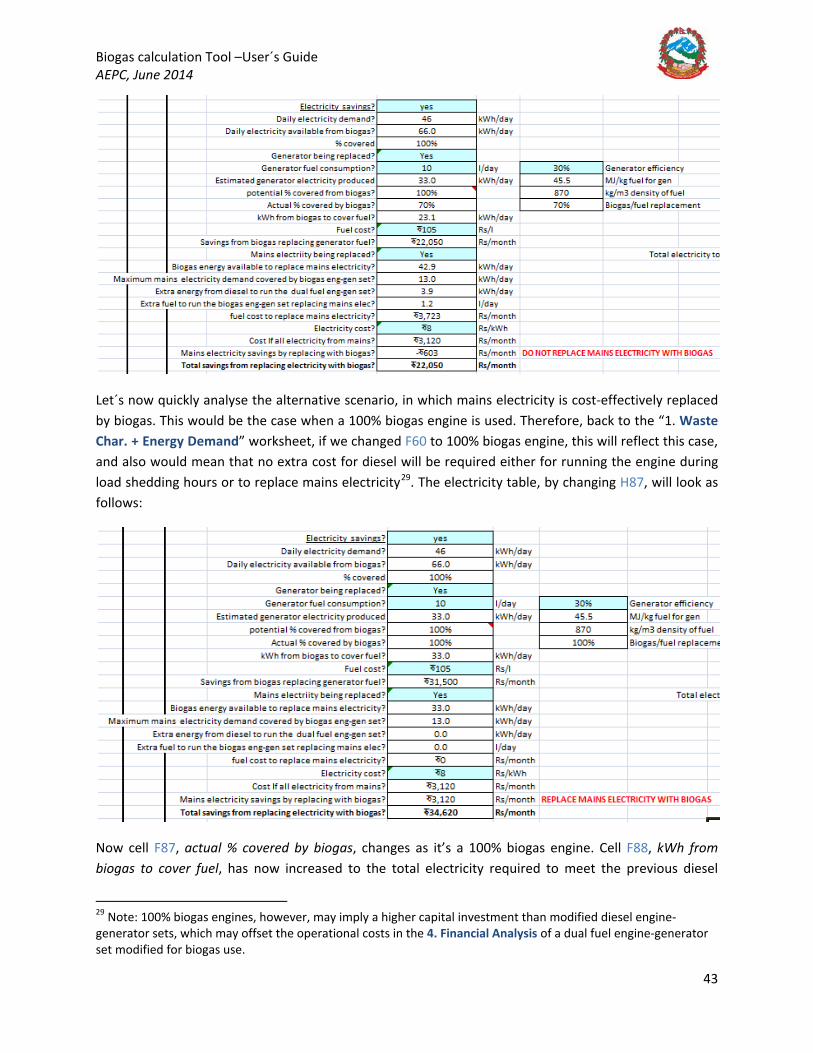
Biogas calculation Tool –User´s Guide AEPC, June 2014
43
Let´s now quickly analyse the alternative scenario, in which mains electricity is cost-effectively replaced by biogas. This would be the case when a 100% biogas engine is used. Therefore, back to the “1. Waste Char. + Energy Demand” worksheet, if we changed F60 to 100% biogas engine, this will reflect this case, and also would mean that no extra cost for diesel will be required either for running the engine during load shedding hours or to replace mains electricity29
. The electricity table, by changing H87, will look as follows:
Now cell F87, actual % covered by biogas, changes as it’s a 100% biogas engine. Cell F88, kWh from biogas to cover fuel, has now increased to the total electricity required to meet the previous diesel
29 Note: 100% biogas engines, however, may imply a higher capital investment than modified diesel engine-generator sets, which may offset the operational costs in the 4. Financial Analysis of a dual fuel engine-generator set modified for biogas use.

Biogas calculation Tool –User´s Guide AEPC, June 2014
44
generator demand (33 kWh), and the savings (F90) have increased accordingly, as there is no cost of fuel to run the engine generator set required, to 31,500 Rs/month.
There is now less biogas electricity available to cover mains electricity (F93) as more of the biogas is used to cover the load shedding period, though still enough to cover the maximum mains electricity demand covered by biogas eng-gen set (F92=33 kWh/day vs F93=13 kWh/day). There is no extra energy requirement from auxiliary fuel as it is a 100% biogas engine, so no fuel required and no cost associated to it (F94=F95=F96=0). The cost of electricity from the mains remains the same (F98=3,120 Rs/month), which can all be saved if biogas is used as there is no cost from fuel (F99 = 3,120 Rs/month). The message in cell H99 would now be to REPLACE MAINS ELECTRICITY WITH BIOGAS, as F99 is positive.
As a result of all the above, the total savings have increased to 34,620 Rs/month, since all diesel from the generator and mains electricity supply are replaced by biogas generated electricity.
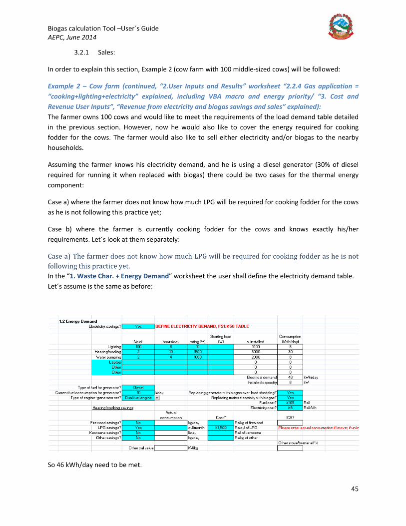
Biogas calculation Tool –User´s Guide AEPC, June 2014
45
3.2.1 Sales:
In order to explain this section, Example 2 (cow farm with 100 middle-sized cows) will be followed:
Example 2 – Cow farm (continued, “2.User Inputs and Results” worksheet “2.2.4 Gas application = “cooking+lighting+electricity” explained, including VBA macro and energy priority/ “3. Cost and Revenue User Inputs”, “Revenue from electricity and biogas savings and sales” explained): The farmer owns 100 cows and would like to meet the requirements of the load demand table detailed in the previous section. However, now he would also like to cover the energy required for cooking fodder for the cows. The farmer would also like to sell either electricity and/or biogas to the nearby households.
Assuming the farmer knows his electricity demand, and he is using a diesel generator (30% of diesel required for running it when replaced with biogas) there could be two cases for the thermal energy component:
Case a) where the farmer does not know how much LPG will be required for cooking fodder for the cows as he is not following this practice yet;
Case b) where the farmer is currently cooking fodder for the cows and knows exactly his/her requirements. Let´s look at them separately:
Case a) The farmer does not know how much LPG will be required for cooking fodder as he is not following this practice yet. In the “1. Waste Char. + Energy Demand” worksheet the user shall define the electricity demand table. Let´s assume is the same as before:
So 46 kWh/day need to be met.
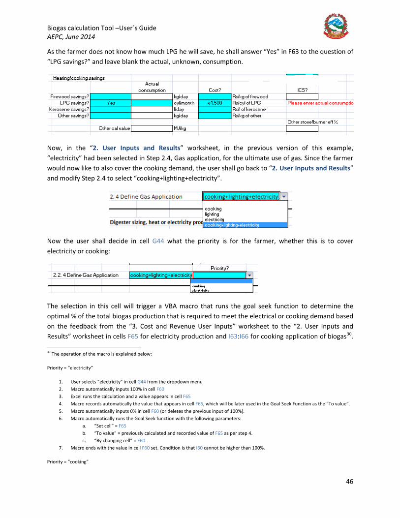
Biogas calculation Tool –User´s Guide AEPC, June 2014
46
As the farmer does not know how much LPG he will save, he shall answer “Yes” in F63 to the question of “LPG savings?” and leave blank the actual, unknown, consumption.
Now, in the “2. User Inputs and Results” worksheet, in the previous version of this example, “electricity” had been selected in Step 2.4, Gas application, for the ultimate use of gas. Since the farmer would now like to also cover the cooking demand, the user shall go back to “2. User Inputs and Results” and modify Step 2.4 to select “cooking+lighting+electricity”.
Now the user shall decide in cell G44 what the priority is for the farmer, whether this is to cover electricity or cooking:
The selection in this cell will trigger a VBA macro that runs the goal seek function to determine the optimal % of the total biogas production that is required to meet the electrical or cooking demand based on the feedback from the “3. Cost and Revenue User Inputs” worksheet to the “2. User Inputs and Results” worksheet in cells F65 for electricity production and I63:I66 for cooking application of biogas30
30 The operation of the macro is explained below:
Priority = “electricity”
.
1. User selects “electricity” in cell G44 from the dropdown menu 2. Macro automatically inputs 100% in cell F60 3. Excel runs the calculation and a value appears in cell F65 4. Macro records automatically the value that appears in cell F65, which will be later used in the Goal Seek Function as the “To value”. 5. Macro automatically inputs 0% in cell F60 (or deletes the previous input of 100%). 6. Macro automatically runs the Goal Seek function with the following parameters:
a. “Set cell” = F65 b. “To value” = previously calculated and recorded value of F65 as per step 4. c. “By changing cell” = F60.
7. Macro ends with the value in cell F60 set. Condition is that I60 cannot be higher than 100%.
Priority = “cooking”

Biogas calculation Tool –User´s Guide AEPC, June 2014
47
If the user selects electricity, the VBA macro would automatically calculate the optimum biogas % to be used for this application in cell F60:
So 35% is the optimum value.
The procedure followed by the macro is explained on how it would be done manually below to illustrate the operation of the macro.
The user shall input 100% in F60.
1. User selects “cooking” in cell G44 from the dropdown menu 2. Macro automatically inputs 100% in cell I60 3. Excel runs the calculation and a value appears in one of the cells from range I63:I66. 4. Macro records automatically the value that appears in whatever cell which is different than “0”, which will be later used in the Goal
Seek Function as the “To value”. 5. Macro automatically inputs 0% in cell I60 (or deletes the previous input of 100%). 6. Macro automatically runs the Goal Seek function to with the following parameters:
a. “Set cell” = whichever cell different to “0” as per step 4 b. “To value” = previously calculated and recorded value of whichever cell different to “0” as per step 4. c. “By changing cell” = I60.
7. Macro ends with the value in cell I60 set. Condition is that I60 cannot be higher than 100%.
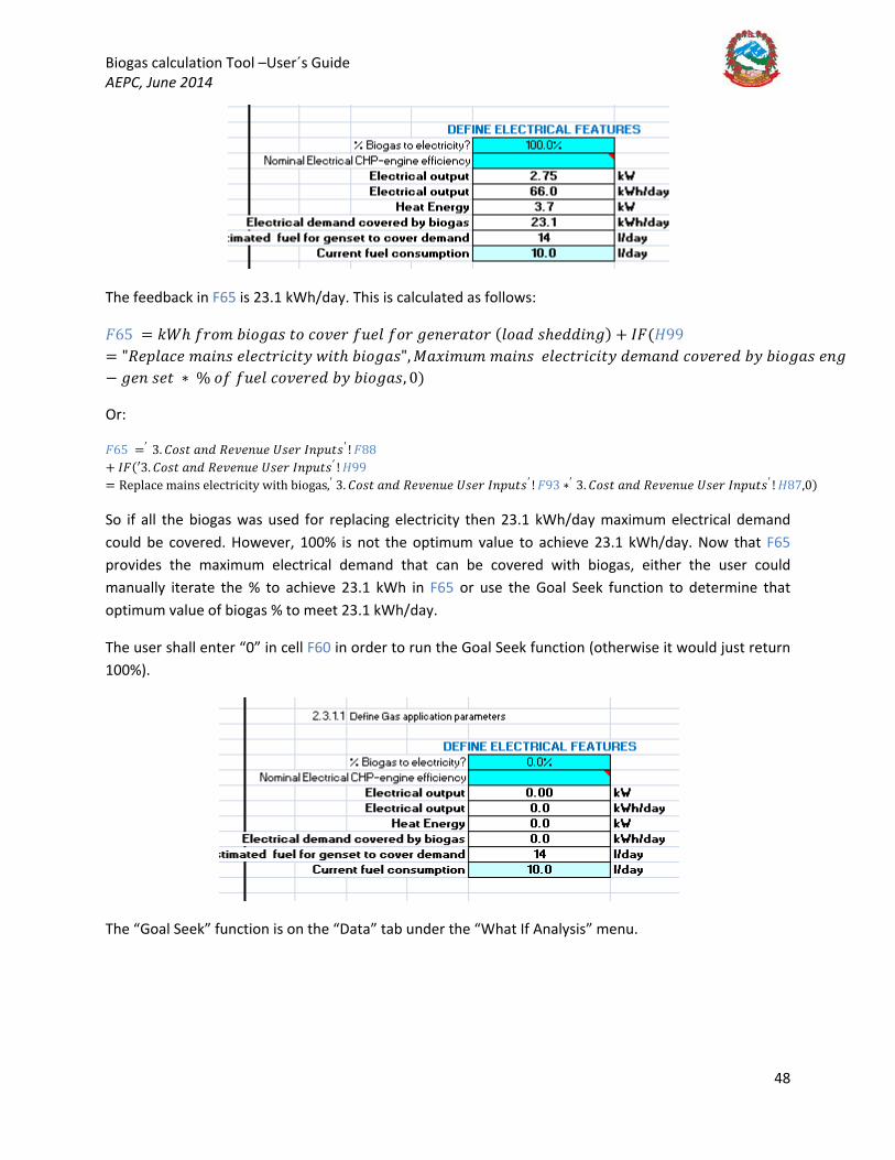
Biogas calculation Tool –User´s Guide AEPC, June 2014
48
The feedback in F65 is 23.1 kWh/day. This is calculated as follows:
𝐹𝐹65 = 𝑘𝑘𝐷𝐷ℎ 𝑜𝑜𝑛𝑛𝐵𝐵𝑚𝑚 𝑛𝑛𝐵𝐵𝐵𝐵𝐵𝐵𝐵𝐵𝐵𝐵 𝑤𝑤𝐵𝐵 𝑖𝑖𝐵𝐵𝑅𝑅𝑦𝑦𝑛𝑛 𝑜𝑜𝑛𝑛𝑦𝑦𝑦𝑦 𝑜𝑜𝐵𝐵𝑛𝑛 𝐵𝐵𝑦𝑦𝑛𝑛𝑦𝑦𝑛𝑛𝐵𝐵𝑤𝑤𝐵𝐵𝑛𝑛 (𝑦𝑦𝐵𝐵𝐵𝐵𝑦𝑦 𝐵𝐵ℎ𝑦𝑦𝑦𝑦𝑦𝑦𝐵𝐵𝑛𝑛𝐵𝐵) + 𝐼𝐼𝐹𝐹(𝐻𝐻99= "𝑂𝑂𝑦𝑦𝑝𝑝𝑦𝑦𝐵𝐵𝑖𝑖𝑦𝑦 𝑚𝑚𝐵𝐵𝐵𝐵𝑛𝑛𝐵𝐵 𝑦𝑦𝑦𝑦𝑦𝑦𝑖𝑖𝑤𝑤𝑛𝑛𝐵𝐵𝑖𝑖𝐵𝐵𝑤𝑤𝑦𝑦 𝑤𝑤𝐵𝐵𝑤𝑤ℎ 𝑛𝑛𝐵𝐵𝐵𝐵𝐵𝐵𝐵𝐵𝐵𝐵", 𝑀𝑀𝐵𝐵𝑒𝑒𝐵𝐵𝑚𝑚𝑛𝑛𝑚𝑚 𝑚𝑚𝐵𝐵𝐵𝐵𝑛𝑛𝐵𝐵 𝑦𝑦𝑦𝑦𝑦𝑦𝑖𝑖𝑤𝑤𝑛𝑛𝐵𝐵𝑖𝑖𝐵𝐵𝑤𝑤𝑦𝑦 𝑦𝑦𝑦𝑦𝑚𝑚𝐵𝐵𝑛𝑛𝑦𝑦 𝑖𝑖𝐵𝐵𝑅𝑅𝑦𝑦𝑛𝑛𝑦𝑦𝑦𝑦 𝑛𝑛𝑦𝑦 𝑛𝑛𝐵𝐵𝐵𝐵𝐵𝐵𝐵𝐵𝐵𝐵 𝑦𝑦𝑛𝑛𝐵𝐵− 𝐵𝐵𝑦𝑦𝑛𝑛 𝐵𝐵𝑦𝑦𝑤𝑤 ∗ % 𝐵𝐵𝑜𝑜 𝑜𝑜𝑛𝑛𝑦𝑦𝑦𝑦 𝑖𝑖𝐵𝐵𝑅𝑅𝑦𝑦𝑛𝑛𝑦𝑦𝑦𝑦 𝑛𝑛𝑦𝑦 𝑛𝑛𝐵𝐵𝐵𝐵𝐵𝐵𝐵𝐵𝐵𝐵, 0)
Or:
𝐹𝐹65 =′ 3. 𝐶𝐶𝐵𝐵𝐵𝐵𝑤𝑤 𝐵𝐵𝑛𝑛𝑦𝑦 𝑂𝑂𝑦𝑦𝑅𝑅𝑦𝑦𝑛𝑛𝑛𝑛𝑦𝑦 𝑈𝑈𝐵𝐵𝑦𝑦𝑛𝑛 𝐼𝐼𝑛𝑛𝑝𝑝𝑛𝑛𝑤𝑤𝐵𝐵′ ! 𝐹𝐹88+ 𝐼𝐼𝐹𝐹(′3. 𝐶𝐶𝐵𝐵𝐵𝐵𝑤𝑤 𝐵𝐵𝑛𝑛𝑦𝑦 𝑂𝑂𝑦𝑦𝑅𝑅𝑦𝑦𝑛𝑛𝑛𝑛𝑦𝑦 𝑈𝑈𝐵𝐵𝑦𝑦𝑛𝑛 𝐼𝐼𝑛𝑛𝑝𝑝𝑛𝑛𝑤𝑤𝐵𝐵′ ! 𝐻𝐻99= Replace mains electricity with biogas,′ 3. 𝐶𝐶𝐵𝐵𝐵𝐵𝑤𝑤 𝐵𝐵𝑛𝑛𝑦𝑦 𝑂𝑂𝑦𝑦𝑅𝑅𝑦𝑦𝑛𝑛𝑛𝑛𝑦𝑦 𝑈𝑈𝐵𝐵𝑦𝑦𝑛𝑛 𝐼𝐼𝑛𝑛𝑝𝑝𝑛𝑛𝑤𝑤𝐵𝐵′ ! 𝐹𝐹93 ∗′ 3. 𝐶𝐶𝐵𝐵𝐵𝐵𝑤𝑤 𝐵𝐵𝑛𝑛𝑦𝑦 𝑂𝑂𝑦𝑦𝑅𝑅𝑦𝑦𝑛𝑛𝑛𝑛𝑦𝑦 𝑈𝑈𝐵𝐵𝑦𝑦𝑛𝑛 𝐼𝐼𝑛𝑛𝑝𝑝𝑛𝑛𝑤𝑤𝐵𝐵′ ! 𝐻𝐻87,0)
So if all the biogas was used for replacing electricity then 23.1 kWh/day maximum electrical demand could be covered. However, 100% is not the optimum value to achieve 23.1 kWh/day. Now that F65 provides the maximum electrical demand that can be covered with biogas, either the user could manually iterate the % to achieve 23.1 kWh in F65 or use the Goal Seek function to determine that optimum value of biogas % to meet 23.1 kWh/day.
The user shall enter “0” in cell F60 in order to run the Goal Seek function (otherwise it would just return 100%).
The “Goal Seek” function is on the “Data” tab under the “What If Analysis” menu.

Biogas calculation Tool –User´s Guide AEPC, June 2014
49
The parameters shall be as follows:
The value of 23.1 is chosen as from the potential electricity that can be replaced as calculated in table F79:F100 from the “3. Cost and Revenue User Inputs” (how this is calculated has been explained in the previous section). The set cell F63 is the one that contains the formula we would like to change, that is, the electrical output in kWh/day.
The result is 35% of the biogas produced (this is F60, cell that is being changed to achieve the value we want in F63) will meet the current demand:
All of the above is what the VBA macro calculates automatically by selecting either “electricity” or “cooking” in cell G44.
So now the user, as the only other application is for cooking (this would also include heating applications) as per the requirements of the farmer, shall put the rest up to 100% in cell I60, that is, enter (1-F60) in cell I60 = 65%.
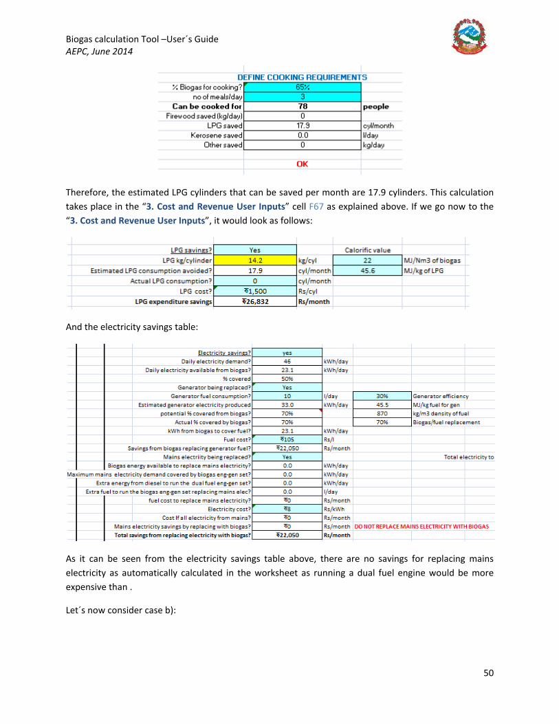
Biogas calculation Tool –User´s Guide AEPC, June 2014
50
Therefore, the estimated LPG cylinders that can be saved per month are 17.9 cylinders. This calculation takes place in the “3. Cost and Revenue User Inputs” cell F67 as explained above. If we go now to the “3. Cost and Revenue User Inputs”, it would look as follows:
And the electricity savings table:
As it can be seen from the electricity savings table above, there are no savings for replacing mains electricity as automatically calculated in the worksheet as running a dual fuel engine would be more expensive than .
Let´s now consider case b):

Biogas calculation Tool –User´s Guide AEPC, June 2014
51
Case b) where the farmer is currently cooking fodder for the cows and knows exactly his requirements. He is currently spending 15 cylinders in cooking fodder for the cows. The user shall now go to the “Waste Char.+Energy Demand” worksheet, and define the energy demand from the farm as explained above, electricity remaining the same, though the LPG consumption would be:
Let´s assume that the farmer´s priority is to cover the electricity demand. Proceeding as above, the results in the “2. User Inputs and Results” worksheet are as follows:
Let´s now assume that the remaining biogas could potentially go for cooking:
The estimated savings of LPG are 17.9 cylinders per month from the biogas available as we saw in case a). However, this saving is not realistic as it is above the demand of 15 cylinders per month, which is what needs to be met by the biogas generated energy. The table above will select the minimum of the actual or the estimated values. In case the actual value is left blank, the table will take the estimated value as it happened in case b).
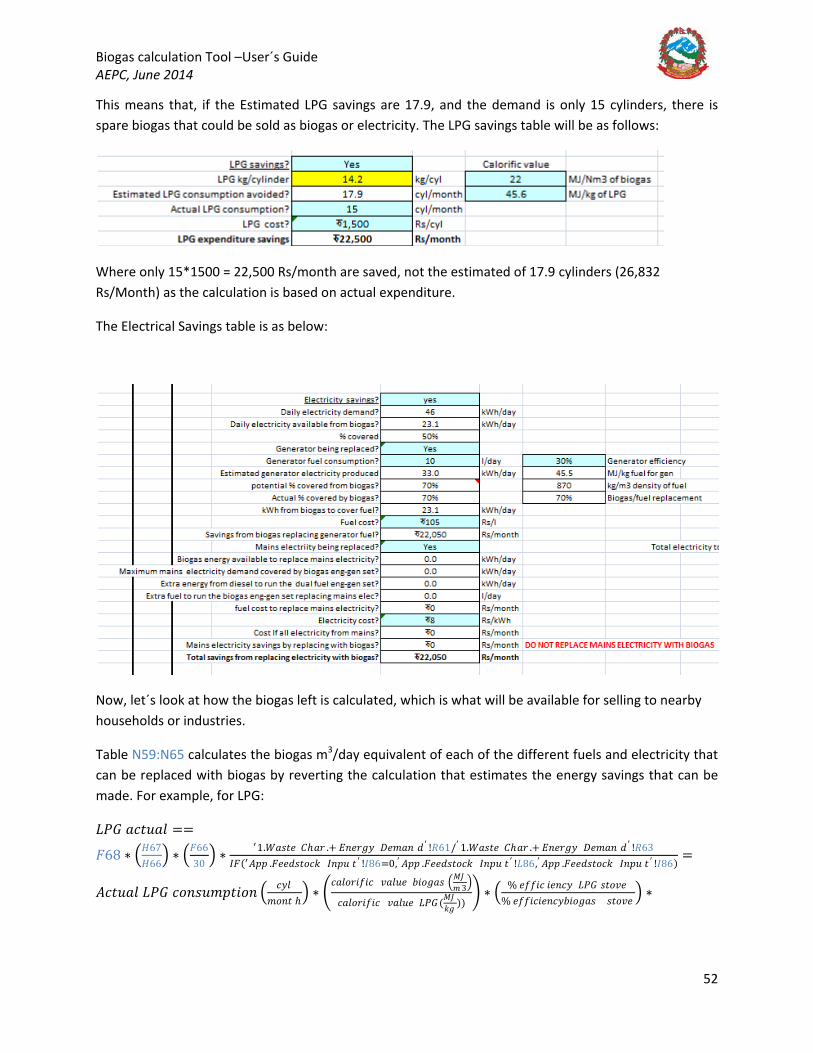
Biogas calculation Tool –User´s Guide AEPC, June 2014
52
This means that, if the Estimated LPG savings are 17.9, and the demand is only 15 cylinders, there is spare biogas that could be sold as biogas or electricity. The LPG savings table will be as follows:
Where only 15*1500 = 22,500 Rs/month are saved, not the estimated of 17.9 cylinders (26,832 Rs/Month) as the calculation is based on actual expenditure.
The Electrical Savings table is as below:
Now, let´s look at how the biogas left is calculated, which is what will be available for selling to nearby households or industries.
Table N59:N65 calculates the biogas m3/day equivalent of each of the different fuels and electricity that can be replaced with biogas by reverting the calculation that estimates the energy savings that can be made. For example, for LPG:
𝐿𝐿𝑃𝑃𝐺𝐺 𝐵𝐵𝑖𝑖𝑤𝑤𝑛𝑛𝐵𝐵𝑦𝑦 ==
𝐹𝐹68 ∗ �𝐻𝐻67𝐻𝐻66
� ∗ �𝐹𝐹6630
� ∗ ′1.𝐷𝐷𝐵𝐵𝐵𝐵𝑤𝑤𝑦𝑦 𝐶𝐶ℎ𝐵𝐵𝑛𝑛 .+ 𝐷𝐷𝑛𝑛𝑦𝑦𝑛𝑛𝐵𝐵𝑦𝑦 𝐴𝐴𝑦𝑦𝑚𝑚𝐵𝐵𝑛𝑛 𝑦𝑦′ !𝑂𝑂61/′ 1.𝐷𝐷𝐵𝐵𝐵𝐵𝑤𝑤𝑦𝑦 𝐶𝐶ℎ𝐵𝐵𝑛𝑛 .+ 𝐷𝐷𝑛𝑛𝑦𝑦𝑛𝑛𝐵𝐵𝑦𝑦 𝐴𝐴𝑦𝑦𝑚𝑚𝐵𝐵𝑛𝑛 𝑦𝑦′ !𝑂𝑂63𝐼𝐼𝐹𝐹(′𝐴𝐴𝑝𝑝𝑝𝑝 .𝐹𝐹𝑦𝑦𝑦𝑦𝑦𝑦𝐵𝐵𝑤𝑤𝐵𝐵𝑖𝑖𝑘𝑘 𝐼𝐼𝑛𝑛𝑝𝑝𝑛𝑛 𝑤𝑤 ′ !𝐼𝐼86=0,′ 𝐴𝐴𝑝𝑝𝑝𝑝 .𝐹𝐹𝑦𝑦𝑦𝑦𝑦𝑦𝐵𝐵𝑤𝑤𝐵𝐵𝑖𝑖𝑘𝑘 𝐼𝐼𝑛𝑛𝑝𝑝𝑛𝑛 𝑤𝑤 ′ !𝐿𝐿86,′ 𝐴𝐴𝑝𝑝𝑝𝑝 .𝐹𝐹𝑦𝑦𝑦𝑦𝑦𝑦𝐵𝐵𝑤𝑤𝐵𝐵𝑖𝑖𝑘𝑘 𝐼𝐼𝑛𝑛𝑝𝑝𝑛𝑛 𝑤𝑤 ′ !𝐼𝐼86) =
𝐴𝐴𝑖𝑖𝑤𝑤𝑛𝑛𝐵𝐵𝑦𝑦 𝐿𝐿𝑃𝑃𝐺𝐺 𝑖𝑖𝐵𝐵𝑛𝑛𝐵𝐵𝑛𝑛𝑚𝑚𝑝𝑝𝑤𝑤𝐵𝐵𝐵𝐵𝑛𝑛 � 𝑖𝑖𝑦𝑦𝑦𝑦𝑚𝑚𝐵𝐵𝑛𝑛𝑤𝑤 ℎ
� ∗ �𝑖𝑖𝐵𝐵𝑦𝑦𝐵𝐵𝑛𝑛𝐵𝐵𝑜𝑜𝐵𝐵𝑖𝑖 𝑅𝑅𝐵𝐵𝑦𝑦𝑛𝑛𝑦𝑦 𝑛𝑛𝐵𝐵𝐵𝐵𝐵𝐵𝐵𝐵𝐵𝐵 �𝑀𝑀𝑀𝑀
𝑚𝑚 3�
𝑖𝑖𝐵𝐵𝑦𝑦𝐵𝐵𝑛𝑛𝐵𝐵𝑜𝑜𝐵𝐵𝑖𝑖 𝑅𝑅𝐵𝐵𝑦𝑦𝑛𝑛𝑦𝑦 𝐿𝐿𝑃𝑃𝐺𝐺 (𝑀𝑀𝑀𝑀𝑘𝑘𝐵𝐵 ))
� ∗ � % 𝑦𝑦𝑜𝑜𝑜𝑜𝐵𝐵𝑖𝑖 𝐵𝐵𝑦𝑦𝑛𝑛𝑖𝑖𝑦𝑦 𝐿𝐿𝑃𝑃𝐺𝐺 𝐵𝐵𝑤𝑤𝐵𝐵𝑅𝑅𝑦𝑦% 𝑦𝑦𝑜𝑜𝑜𝑜𝐵𝐵𝑖𝑖𝐵𝐵𝑦𝑦𝑛𝑛𝑖𝑖𝑦𝑦𝑛𝑛𝐵𝐵𝐵𝐵𝐵𝐵𝐵𝐵𝐵𝐵 𝐵𝐵𝑤𝑤𝐵𝐵𝑅𝑅𝑦𝑦
� ∗
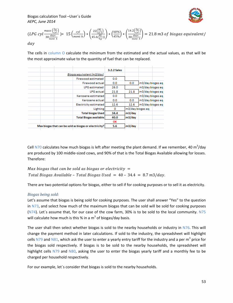
Biogas calculation Tool –User´s Guide AEPC, June 2014
53
(𝐿𝐿𝑃𝑃𝐺𝐺 𝑖𝑖𝑦𝑦𝑦𝑦𝑚𝑚𝐵𝐵𝐵𝐵𝐵𝐵 � 𝑘𝑘𝐵𝐵
𝑖𝑖𝑦𝑦𝑦𝑦 �
30 𝑦𝑦𝐵𝐵𝑦𝑦𝐵𝐵𝑚𝑚𝐵𝐵𝑛𝑛𝑤𝑤 ℎ
)= 15 � 𝑖𝑖𝑦𝑦𝑦𝑦𝑚𝑚𝐵𝐵𝑛𝑛𝑤𝑤 ℎ
� ∗ �22�𝑀𝑀𝑀𝑀
𝑚𝑚 3�
45.6(𝑀𝑀𝑀𝑀𝑘𝑘𝐵𝐵 ))
� ∗ �60%45%
� ∗ �14.2� 𝑘𝑘𝐵𝐵
𝑖𝑖𝑦𝑦𝑦𝑦 �
30 𝑦𝑦𝐵𝐵𝑦𝑦𝐵𝐵𝑚𝑚𝐵𝐵𝑛𝑛𝑤𝑤 ℎ
� = 21.8 𝑚𝑚3 𝐵𝐵𝑜𝑜 𝑛𝑛𝐵𝐵𝐵𝐵𝐵𝐵𝐵𝐵𝐵𝐵 𝑦𝑦𝑒𝑒𝑛𝑛𝐵𝐵𝑅𝑅𝐵𝐵𝑦𝑦𝑦𝑦𝑛𝑛𝑤𝑤/
𝑦𝑦𝐵𝐵𝑦𝑦
The cells in column O calculate the minimum from the estimated and the actual values, as that will be the most approximate value to the quantity of fuel that can be replaced.
Cell N70 calculates how much biogas is left after meeting the plant demand. If we remember, 40 m3/day are produced by 100 middle-sized cows, and 90% of that is the Total Biogas Available allowing for losses. Therefore:
𝑀𝑀𝐵𝐵𝑒𝑒 𝑛𝑛𝐵𝐵𝐵𝐵𝐵𝐵𝐵𝐵𝐵𝐵 𝑤𝑤ℎ𝐵𝐵𝑤𝑤 𝑖𝑖𝐵𝐵𝑛𝑛 𝑛𝑛𝑦𝑦 𝐵𝐵𝐵𝐵𝑦𝑦𝑦𝑦 𝐵𝐵𝐵𝐵 𝑛𝑛𝐵𝐵𝐵𝐵𝐵𝐵𝐵𝐵𝐵𝐵 𝐵𝐵𝑛𝑛 𝑦𝑦𝑦𝑦𝑦𝑦𝑖𝑖𝑤𝑤𝑛𝑛𝐵𝐵𝑖𝑖𝐵𝐵𝑤𝑤𝑦𝑦 = 𝑇𝑇𝐵𝐵𝑤𝑤𝐵𝐵𝑦𝑦 𝐵𝐵𝐵𝐵𝐵𝐵𝐵𝐵𝐵𝐵𝐵𝐵 𝐴𝐴𝑅𝑅𝐵𝐵𝐵𝐵𝑦𝑦𝐵𝐵𝑛𝑛𝑦𝑦𝑦𝑦 – 𝑇𝑇𝐵𝐵𝑤𝑤𝐵𝐵𝑦𝑦 𝐵𝐵𝐵𝐵𝐵𝐵𝐵𝐵𝐵𝐵𝐵𝐵 𝑈𝑈𝐵𝐵𝑦𝑦𝑦𝑦 = 40 – 34.4 = 8.7 𝑚𝑚3/𝑦𝑦𝐵𝐵𝑦𝑦.
There are two potential options for biogas, either to sell if for cooking purposes or to sell it as electricity.
Biogas being sold: Let’s assume that biogas is being sold for cooking purposes. The user shall answer “Yes” to the question in N73, and select how much of the maximum biogas that can be sold will be sold for cooking purposes (N74). Let´s assume that, for our case of the cow farm, 30% is to be sold to the local community. N75 will calculate how much is this % in a m3 of biogas/day basis.
The user shall then select whether biogas is sold to the nearby households or industry in N76. This will change the payment method in later calculations. If sold to the industry, the spreadsheet will highlight cells N79 and N81, which ask the user to enter a yearly entry tariff for the industry and a per m3 price for the biogas sold respectively. If biogas is to be sold to the nearby households, the spreadsheet will highlight cells N79 and N80, asking the user to enter the biogas yearly tariff and a monthly fee to be charged per household respectively.
For our example, let´s consider that biogas is sold to the nearby households.

Biogas calculation Tool –User´s Guide AEPC, June 2014
54
Cell N77 calculates how many people can benefit from the biogas produced for cooking purposes as follows:
𝑁𝑁77 = 𝑃𝑃𝑦𝑦𝐵𝐵𝑝𝑝𝑦𝑦𝑦𝑦 𝑖𝑖𝐵𝐵𝑛𝑛 𝑛𝑛𝑦𝑦 𝐵𝐵𝐵𝐵𝑦𝑦𝑦𝑦 𝑤𝑤𝐵𝐵? =𝑁𝑁75
3 ∗ ′𝐹𝐹𝑦𝑦𝑦𝑦𝑦𝑦𝐵𝐵𝑤𝑤𝐵𝐵𝑖𝑖𝑘𝑘 𝐵𝐵𝑛𝑛𝑝𝑝𝑛𝑛𝑤𝑤′! 𝑂𝑂103 =
𝐵𝐵𝐵𝐵𝐵𝐵𝐵𝐵𝐵𝐵𝐵𝐵 𝐵𝐵𝐵𝐵𝑦𝑦𝑦𝑦 ( 𝑚𝑚3𝑦𝑦𝐵𝐵𝑦𝑦)
3 𝑚𝑚𝑦𝑦𝐵𝐵𝑦𝑦𝐵𝐵𝑦𝑦𝐵𝐵𝑦𝑦 ∗ 𝑚𝑚3 /
(𝑚𝑚𝑦𝑦𝐵𝐵𝑦𝑦 ∗ 𝑝𝑝𝑦𝑦𝑛𝑛𝐵𝐵𝐵𝐵𝑛𝑛)= 1.7/(3 ∗ 0.1) = 6 𝑝𝑝𝑦𝑦𝐵𝐵𝑝𝑝𝑦𝑦𝑦𝑦
The spreadsheet assumes, in T91, that a household is made of 5 people. Therefore, the biogas available, calculated in
𝑁𝑁78 = 𝑁𝑁77𝑇𝑇91
= 𝑛𝑛𝑛𝑛𝑚𝑚𝑛𝑛𝑦𝑦𝑛𝑛 𝐵𝐵𝑜𝑜 𝑝𝑝𝑦𝑦𝐵𝐵𝑝𝑝𝑦𝑦𝑦𝑦 𝑤𝑤ℎ𝐵𝐵𝑤𝑤 𝑖𝑖𝐵𝐵𝑛𝑛 𝑛𝑛𝑦𝑦 𝑖𝑖𝐵𝐵𝐵𝐵𝑘𝑘𝑦𝑦𝑦𝑦 𝑜𝑜𝐵𝐵𝑛𝑛5 𝑝𝑝𝑦𝑦𝐵𝐵𝑝𝑝𝑦𝑦𝑦𝑦
ℎ 𝐵𝐵𝑛𝑛𝐵𝐵𝑦𝑦 ℎ 𝐵𝐵𝑦𝑦𝑦𝑦
= 1 ℎ𝐵𝐵𝑛𝑛𝐵𝐵𝑦𝑦ℎ𝐵𝐵𝑦𝑦𝑦𝑦𝐵𝐵
Let´s now assume that the user sets a biogas entry tariff of 400 Rs/year, and that the monthly tariff is of 300 Rs/month31
𝑁𝑁82 = 𝑁𝑁77 ∗ 𝑁𝑁82, 𝐵𝐵𝑛𝑛 𝑛𝑛𝐵𝐵𝐵𝐵𝐵𝐵𝐵𝐵𝐵𝐵 𝑦𝑦𝑛𝑛𝑤𝑤𝑛𝑛𝑦𝑦 𝑤𝑤𝐵𝐵𝑛𝑛𝐵𝐵𝑜𝑜𝑜𝑜 ∗ 𝑛𝑛𝑛𝑛𝑚𝑚𝑛𝑛𝑦𝑦𝑛𝑛 𝐵𝐵𝑜𝑜 ℎ𝐵𝐵𝑛𝑛𝐵𝐵𝑦𝑦ℎ𝐵𝐵𝑦𝑦𝑦𝑦𝐵𝐵.
The biogas revenue is calculated depending on whether biogas is sold to an industry or to nearby households by calculating the revenue per m3 of biogas (industry) or the revenue per monthly fee (household) as follows:
𝑁𝑁83 = 𝐼𝐼𝐹𝐹(𝑁𝑁76 = "𝐼𝐼𝑛𝑛𝑦𝑦𝑛𝑛𝐵𝐵𝑤𝑤𝑛𝑛𝑦𝑦", 𝑁𝑁81 ∗ 𝑁𝑁75, 𝐼𝐼𝐹𝐹(𝑁𝑁76 = "𝐻𝐻𝐵𝐵𝑛𝑛𝐵𝐵𝑦𝑦ℎ𝐵𝐵𝑦𝑦𝑦𝑦𝐵𝐵", 𝑁𝑁80 ∗ 𝑁𝑁78,0)
The table will look as follows:
.
The biogas tariff revenue (N82) is calculated as
31 When setting the tariffs the user shall account for the fuel to be replaced. For instance, if we assume that LPG is replaced, and current price is 1500 Rs/cylinder, and 1 household consumes 1 cylinder/45 days, then their current monthly expenditure would be 1000 Rs/month for cooking with LPG. Therefore, setting a price of 300 Rs/month presents an advantage for the potential customers, and therefore creates a market for biogas.
Biogas calculation Tool –User´s Guide AEPC, June 2014
55
Electricity being sold: Electricity can also be sold for profit. In this case, the user shall select “Yes” to N86. Cell N87 calculates the remaining % out of the maximum biogas that can be sold (N70) by subtracting from it the % used for selling biogas for cooking (N74):
𝑁𝑁87 = 𝐼𝐼𝐹𝐹(𝑁𝑁86 = "𝑌𝑌𝑦𝑦𝐵𝐵", 1 − 𝑁𝑁74,0)
The biogas that could potentially be used for producing electricity is calculated as N87*N70. In our case, as 30% out of the total 5.6 m3/day is sold for cooking, that leaves 70% for electricity, that is, 3.9 m3/day. The quantity of electricity that this amount of biogas can produce is calculated in cell N89 as follows:
𝑇𝑇𝐵𝐵𝑤𝑤𝐵𝐵𝑦𝑦 𝑦𝑦𝑦𝑦𝑦𝑦𝑖𝑖𝑤𝑤𝑛𝑛𝐵𝐵𝑖𝑖𝐵𝐵𝑤𝑤𝑦𝑦 𝑤𝑤ℎ𝐵𝐵𝑤𝑤 𝑖𝑖𝐵𝐵𝑛𝑛 𝑛𝑛𝑦𝑦 𝑝𝑝𝑛𝑛𝐵𝐵𝑦𝑦𝑛𝑛𝑖𝑖𝑦𝑦𝑦𝑦 𝑜𝑜𝑛𝑛𝐵𝐵𝑚𝑚 𝑛𝑛𝐵𝐵𝐵𝐵𝐵𝐵𝐵𝐵𝐵𝐵 = 𝑁𝑁89 = 𝑁𝑁88 ∗ 𝐻𝐻74 ∗ 𝑇𝑇71 ∗ 𝐻𝐻84 = 𝐵𝐵𝐵𝐵𝐵𝐵𝐵𝐵𝐵𝐵𝐵𝐵 𝑛𝑛𝐵𝐵𝑦𝑦𝑦𝑦 𝑤𝑤𝐵𝐵 𝑝𝑝𝑛𝑛𝐵𝐵𝑦𝑦𝑛𝑛𝑖𝑖𝑦𝑦 𝑦𝑦𝑦𝑦𝑦𝑦𝑖𝑖𝑤𝑤𝑛𝑛𝐵𝐵𝑖𝑖𝐵𝐵𝑤𝑤𝑦𝑦 𝑤𝑤𝐵𝐵 𝑛𝑛𝑦𝑦 𝐵𝐵𝐵𝐵𝑦𝑦𝑦𝑦 ∗ 𝐵𝐵𝐵𝐵𝐵𝐵𝐵𝐵𝐵𝐵𝐵𝐵 𝑖𝑖𝐵𝐵𝑦𝑦𝐵𝐵𝑛𝑛𝐵𝐵𝑜𝑜𝐵𝐵𝑖𝑖 𝑅𝑅𝐵𝐵𝑦𝑦𝑛𝑛𝑦𝑦
∗ 0.278𝑘𝑘𝐷𝐷ℎ𝑀𝑀𝑀𝑀
∗ 𝐺𝐺𝑦𝑦𝑛𝑛𝑦𝑦𝑛𝑛𝐵𝐵𝑤𝑤𝐵𝐵𝑛𝑛 𝑦𝑦𝑦𝑦𝑦𝑦𝑖𝑖𝑤𝑤𝑛𝑛𝐵𝐵𝑖𝑖𝐵𝐵𝑦𝑦 𝑦𝑦𝑜𝑜𝑜𝑜𝐵𝐵𝑖𝑖𝐵𝐵𝑦𝑦𝑛𝑛𝑖𝑖𝑦𝑦
= 3.9𝑚𝑚3𝑦𝑦𝐵𝐵𝑦𝑦
∗ 22 𝑀𝑀𝑀𝑀/𝑚𝑚3 ∗ 0.278 𝑘𝑘𝐷𝐷ℎ/𝑀𝑀𝑀𝑀 ∗ 30% = 7.2 𝑘𝑘𝐷𝐷ℎ/𝑦𝑦𝐵𝐵𝑦𝑦
As the engine generator set may be a dual fuel one, where diesel or other fuel needs to be used as an auxiliary fuel to run it, the total electricity produced would depend on how much biogas replaces as a % of the generator. Therefore, the above value of 7.2 kWh/day, for an engine-generator set where biogas is 70% of the total, the total electricity produced would be higher, calculated in N90 as follows:
𝑁𝑁90 = 𝑁𝑁89 ∗ 100%/𝐵𝐵𝐵𝐵𝐵𝐵𝐵𝐵𝐵𝐵𝐵𝐵/𝑜𝑜𝑛𝑛𝑦𝑦𝑦𝑦 𝑛𝑛𝑦𝑦𝑝𝑝𝑦𝑦𝐵𝐵𝑖𝑖𝑦𝑦𝑚𝑚𝑦𝑦𝑛𝑛𝑤𝑤 = 7.2 𝑘𝑘𝐷𝐷ℎ ∗ 100%/70% = 10.3 𝑘𝑘𝐷𝐷ℎ/𝑦𝑦𝐵𝐵𝑦𝑦. 32
Out of this total, 30%, or the difference between the total electricity produced by the engine-generator set and that of biogas, is the electricity produced by the diesel (N91):
𝑇𝑇𝐵𝐵𝑤𝑤𝐵𝐵𝑦𝑦 𝑦𝑦𝑦𝑦𝑦𝑦𝑖𝑖𝑤𝑤𝑛𝑛𝐵𝐵𝑖𝑖𝐵𝐵𝑤𝑤𝑦𝑦 𝑤𝑤𝐵𝐵 𝑛𝑛𝑦𝑦 𝑝𝑝𝑛𝑛𝐵𝐵𝑦𝑦𝑛𝑛𝑖𝑖𝑦𝑦𝑦𝑦 𝑛𝑛𝑦𝑦 𝑤𝑤ℎ𝑦𝑦 𝑜𝑜𝑛𝑛𝑦𝑦𝑦𝑦 𝑛𝑛𝑦𝑦𝑒𝑒𝑛𝑛𝐵𝐵𝑛𝑛𝑦𝑦𝑦𝑦 𝑤𝑤𝐵𝐵 𝑛𝑛𝑛𝑛𝑛𝑛 𝑤𝑤ℎ𝑦𝑦 𝑦𝑦𝑛𝑛𝐵𝐵 − 𝐵𝐵𝑦𝑦𝑛𝑛 𝐵𝐵𝑦𝑦𝑤𝑤 = 𝑁𝑁91= 𝑇𝑇𝐵𝐵𝑤𝑤𝐵𝐵𝑦𝑦 𝑦𝑦𝑦𝑦𝑦𝑦𝑖𝑖𝑤𝑤𝑛𝑛𝐵𝐵𝑖𝑖𝐵𝐵𝑤𝑤𝑦𝑦 𝑤𝑤𝐵𝐵 𝑛𝑛𝑦𝑦 𝑝𝑝𝑛𝑛𝐵𝐵𝑦𝑦𝑛𝑛𝑖𝑖𝑦𝑦𝑦𝑦 𝑛𝑛𝑦𝑦 𝑤𝑤ℎ𝑦𝑦 𝑦𝑦𝑛𝑛𝐵𝐵𝐵𝐵𝑛𝑛𝑦𝑦 − 𝐵𝐵𝑦𝑦𝑛𝑛 𝐵𝐵𝑦𝑦𝑤𝑤 − 𝑇𝑇𝐵𝐵𝑤𝑤𝐵𝐵𝑦𝑦 𝑦𝑦𝑦𝑦𝑦𝑦𝑖𝑖𝑤𝑤𝑛𝑛𝐵𝐵𝑖𝑖𝐵𝐵𝑤𝑤𝑦𝑦 𝑤𝑤ℎ𝐵𝐵𝑤𝑤 𝑖𝑖𝐵𝐵𝑛𝑛 𝑛𝑛𝑦𝑦 𝑝𝑝𝑛𝑛𝐵𝐵𝑦𝑦𝑛𝑛𝑖𝑖𝑦𝑦𝑦𝑦 𝑜𝑜𝑛𝑛𝐵𝐵𝑚𝑚 𝑛𝑛𝐵𝐵𝐵𝐵𝐵𝐵𝐵𝐵𝐵𝐵 = 𝑁𝑁90 − 𝑁𝑁89 == 10.3 − 7.2 = 3.1 kWh/day
The fuel required to produce 3.1 kWh/day is calculated in cell N92 as follows:
32 If this were a biogas 100% engine, then no fuel would be required to run it and the electricity production would be that of biogas only, that is, in our case, 11. kWh/day.

Biogas calculation Tool –User´s Guide AEPC, June 2014
56
𝐹𝐹𝑛𝑛𝑦𝑦𝑦𝑦 𝑛𝑛𝑦𝑦𝑒𝑒𝑛𝑛𝐵𝐵𝑛𝑛𝑦𝑦𝑦𝑦 𝑤𝑤𝐵𝐵 𝑛𝑛𝑛𝑛𝑛𝑛 𝑤𝑤ℎ𝑦𝑦 𝑦𝑦𝑛𝑛𝐵𝐵𝐵𝐵𝑛𝑛𝑦𝑦 − 𝐵𝐵𝑦𝑦𝑛𝑛𝑦𝑦𝑛𝑛𝐵𝐵𝑤𝑤𝐵𝐵𝑛𝑛 𝐵𝐵𝑦𝑦𝑤𝑤 = 𝑁𝑁92
=𝑇𝑇𝐵𝐵𝑤𝑤𝐵𝐵𝑦𝑦 𝑦𝑦𝑦𝑦𝑦𝑦𝑖𝑖𝑤𝑤𝑛𝑛𝐵𝐵𝑖𝑖𝐵𝐵𝑤𝑤𝑦𝑦 𝑤𝑤𝐵𝐵 𝑛𝑛𝑦𝑦 𝑝𝑝𝑛𝑛𝐵𝐵𝑦𝑦𝑛𝑛𝑖𝑖𝑦𝑦𝑦𝑦 𝑛𝑛𝑦𝑦 𝑤𝑤ℎ𝑦𝑦 𝑜𝑜𝑛𝑛𝑦𝑦𝑦𝑦 𝑛𝑛𝑦𝑦𝑒𝑒𝑛𝑛𝐵𝐵𝑛𝑛𝑦𝑦𝑦𝑦 𝑤𝑤𝐵𝐵 𝑛𝑛𝑛𝑛𝑛𝑛 𝑤𝑤ℎ𝑦𝑦 𝑦𝑦𝑛𝑛𝐵𝐵 − 𝐵𝐵𝑦𝑦𝑛𝑛 𝐵𝐵𝑦𝑦𝑤𝑤(𝑘𝑘𝐷𝐷ℎ/𝑦𝑦𝐵𝐵𝑦𝑦)
𝑦𝑦𝑦𝑦𝑛𝑛𝐵𝐵𝐵𝐵𝑤𝑤𝑦𝑦 𝐵𝐵𝑜𝑜 𝑜𝑜𝑛𝑛𝑦𝑦𝑦𝑦 �𝑘𝑘𝐵𝐵𝑚𝑚3� ∗ 𝑖𝑖𝐵𝐵𝑦𝑦 𝑅𝑅𝐵𝐵𝑦𝑦𝑛𝑛𝑦𝑦 𝐵𝐵𝑜𝑜 𝑜𝑜𝑛𝑛𝑦𝑦𝑦𝑦 �𝑀𝑀𝑀𝑀
𝑘𝑘𝐵𝐵� ∗ 278(𝑘𝑘𝐷𝐷ℎ𝑀𝑀𝑀𝑀 ) ∗ 𝐵𝐵𝑦𝑦𝑛𝑛𝑦𝑦𝑛𝑛𝐵𝐵𝑤𝑤𝐵𝐵𝑛𝑛 𝑦𝑦𝑜𝑜𝑜𝑜𝐵𝐵𝑖𝑖𝐵𝐵𝑦𝑦𝑛𝑛𝑖𝑖𝑦𝑦(%)
1000(𝑦𝑦/𝑚𝑚3)
=𝑁𝑁91
𝐻𝐻86 ∗ 𝐻𝐻85 ∗ 𝑇𝑇71 ∗ 𝐻𝐻841000
=3.1 (𝑘𝑘𝐷𝐷ℎ
𝑦𝑦𝐵𝐵𝑦𝑦 )
870 �𝑘𝑘𝐵𝐵𝑚𝑚3� ∗ 22(𝑀𝑀𝑀𝑀
𝑘𝑘𝐵𝐵) ∗ 0.278(𝑘𝑘𝐷𝐷ℎ𝑀𝑀𝑀𝑀 ) ∗ 30%
1000 � 𝑦𝑦𝑚𝑚3�
= 0.9 𝑦𝑦 𝐵𝐵𝑜𝑜 𝑦𝑦𝐵𝐵𝑦𝑦𝐵𝐵𝑦𝑦𝑦𝑦/𝑦𝑦𝐵𝐵𝑦𝑦
Cell N93, based on this, calculates the expenditure on fuel required to run the engine based on the unit cost of fuel set in cell F89:
𝐶𝐶𝐵𝐵𝐵𝐵𝑤𝑤 𝐵𝐵𝑜𝑜 𝑜𝑜𝑛𝑛𝑦𝑦𝑦𝑦 𝑤𝑤𝐵𝐵 𝑛𝑛𝑛𝑛𝑛𝑛 𝑤𝑤ℎ𝑦𝑦 𝑦𝑦𝑛𝑛𝐵𝐵𝐵𝐵𝑛𝑛𝑦𝑦 − 𝐵𝐵𝑦𝑦𝑛𝑛𝑦𝑦𝑛𝑛𝐵𝐵𝑤𝑤𝐵𝐵𝑛𝑛 𝐵𝐵𝑦𝑦𝑤𝑤 = 𝑁𝑁93 = 𝑁𝑁92 ∗ 𝐹𝐹89 ∗ 30
= 𝑜𝑜𝑛𝑛𝑦𝑦𝑦𝑦 𝑛𝑛𝑦𝑦𝑒𝑒𝑛𝑛𝐵𝐵𝑛𝑛𝑦𝑦𝑦𝑦 𝑤𝑤𝐵𝐵 𝑛𝑛𝑛𝑛𝑛𝑛 𝑤𝑤ℎ𝑦𝑦 𝑦𝑦𝑛𝑛𝐵𝐵𝐵𝐵𝑛𝑛𝑦𝑦 �𝑦𝑦
𝑦𝑦𝐵𝐵𝑦𝑦� ∗ 𝑜𝑜𝑛𝑛𝑦𝑦𝑦𝑦 𝑖𝑖𝐵𝐵𝐵𝐵𝑤𝑤 �
𝑂𝑂𝐵𝐵𝑦𝑦
� ∗ 30 �𝑦𝑦𝐵𝐵𝑦𝑦𝐵𝐵
𝑚𝑚𝐵𝐵𝑛𝑛𝑤𝑤ℎ�
= 0.9𝑦𝑦
𝑦𝑦𝐵𝐵𝑦𝑦∗ 105
𝑂𝑂𝐵𝐵𝑦𝑦
∗ 30𝑦𝑦𝐵𝐵𝑦𝑦𝐵𝐵
𝑚𝑚𝐵𝐵𝑛𝑛𝑤𝑤ℎ= 2,939 𝑂𝑂𝐵𝐵/𝑚𝑚𝐵𝐵𝑛𝑛𝑤𝑤ℎ
It is important to consider this cost as it will be later used to compare it against the revenue created from selling electricity and help determine the cost per kWh to be sold at in order to make the investment profitable.
In cell N94 the user shall input the electricity tariff that will be charged to the consumers per household or industry.
Let´s assume for our example that electricity is to be sold to 10 nearby households, and that 500 Rs/year of entry tariff will be charged. The user shall enter, therefore, 500 and 10 in cells N94 and N95. Cell N96 calculates the number of people served based on the 5 people/household figure from cell T91, and this value is used in cell N97, to calculate the electricity supply per capita per year, as follows:
𝑁𝑁97 = 𝑁𝑁90/𝑁𝑁96 ∗ 365= 𝑇𝑇𝐵𝐵𝑤𝑤𝐵𝐵𝑦𝑦 𝑦𝑦𝑦𝑦𝑦𝑦𝑖𝑖𝑤𝑤𝑛𝑛𝐵𝐵𝑖𝑖𝐵𝐵𝑤𝑤𝑦𝑦 𝑤𝑤𝐵𝐵 𝑛𝑛𝑦𝑦 𝑝𝑝𝑛𝑛𝐵𝐵𝑦𝑦𝑛𝑛𝑖𝑖𝑦𝑦𝑦𝑦 𝑛𝑛𝑦𝑦 𝑤𝑤ℎ𝑦𝑦 𝑦𝑦𝑛𝑛𝐵𝐵𝐵𝐵𝑛𝑛𝑦𝑦− 𝐵𝐵𝑦𝑦𝑛𝑛 𝐵𝐵𝑦𝑦𝑤𝑤 (𝑘𝑘𝐷𝐷ℎ/𝑦𝑦𝐵𝐵𝑦𝑦)/𝑁𝑁𝐵𝐵 𝐵𝐵𝑜𝑜 𝑝𝑝𝑦𝑦𝐵𝐵𝑝𝑝𝑦𝑦𝑦𝑦 𝐵𝐵𝑦𝑦𝑛𝑛𝑅𝑅𝑦𝑦𝑦𝑦 ∗ 365 𝑦𝑦𝐵𝐵𝑦𝑦𝐵𝐵/𝑦𝑦𝑦𝑦𝐵𝐵𝑛𝑛= 10.3 𝑘𝑘𝐷𝐷ℎ/𝑦𝑦𝐵𝐵𝑦𝑦 ∗ 50 𝑝𝑝𝑦𝑦𝐵𝐵𝑝𝑝𝑦𝑦𝑦𝑦 ∗ 365 𝑦𝑦𝐵𝐵𝑦𝑦𝐵𝐵/𝑦𝑦𝑦𝑦𝐵𝐵𝑛𝑛 = 75 𝑘𝑘𝐷𝐷ℎ/𝑖𝑖𝐵𝐵𝑝𝑝𝐵𝐵𝑤𝑤𝐵𝐵/𝑦𝑦𝑦𝑦𝐵𝐵𝑛𝑛
This calculation has no other purpose than to provide the user with a reference value to compare it against Nepal´s average yearly per capita electricity consumption, which is in the range of 130 kWh/cap/year33
33
. This will help the user determining roughly how many people can be served by the available electricity, though, strictly, at the detailed feasibility stage, the user shall do an electricity demand assessment of the households or industries to be served.
http://wecs-neep.gov.np/article-energy_situation_nepal
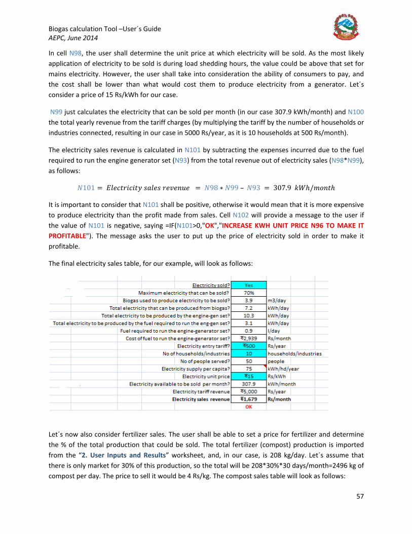
Biogas calculation Tool –User´s Guide AEPC, June 2014
57
In cell N98, the user shall determine the unit price at which electricity will be sold. As the most likely application of electricity to be sold is during load shedding hours, the value could be above that set for mains electricity. However, the user shall take into consideration the ability of consumers to pay, and the cost shall be lower than what would cost them to produce electricity from a generator. Let´s consider a price of 15 Rs/kWh for our case.
N99 just calculates the electricity that can be sold per month (in our case 307.9 kWh/month) and N100 the total yearly revenue from the tariff charges (by multiplying the tariff by the number of households or industries connected, resulting in our case in 5000 Rs/year, as it is 10 households at 500 Rs/month).
The electricity sales revenue is calculated in N101 by subtracting the expenses incurred due to the fuel required to run the engine generator set (N93) from the total revenue out of electricity sales (N98*N99), as follows:
𝑁𝑁101 = 𝐷𝐷𝑦𝑦𝑦𝑦𝑖𝑖𝑤𝑤𝑛𝑛𝐵𝐵𝑖𝑖𝐵𝐵𝑤𝑤𝑦𝑦 𝐵𝐵𝐵𝐵𝑦𝑦𝑦𝑦𝐵𝐵 𝑛𝑛𝑦𝑦𝑅𝑅𝑦𝑦𝑛𝑛𝑛𝑛𝑦𝑦 = 𝑁𝑁98 ∗ 𝑁𝑁99 – 𝑁𝑁93 = 307.9 𝑘𝑘𝐷𝐷ℎ/𝑚𝑚𝐵𝐵𝑛𝑛𝑤𝑤ℎ
It is important to consider that N101 shall be positive, otherwise it would mean that it is more expensive to produce electricity than the profit made from sales. Cell N102 will provide a message to the user if the value of N101 is negative, saying =IF(N101>0,"OK","INCREASE KWH UNIT PRICE N96 TO MAKE IT PROFITABLE"). The message asks the user to put up the price of electricity sold in order to make it profitable.
The final electricity sales table, for our example, will look as follows:
Let´s now also consider fertilizer sales. The user shall be able to set a price for fertilizer and determine the % of the total production that could be sold. The total fertilizer (compost) production is imported from the “2. User Inputs and Results” worksheet, and, in our case, is 208 kg/day. Let´s assume that there is only market for 30% of this production, so the total will be 208*30%*30 days/month=2496 kg of compost per day. The price to sell it would be 4 Rs/kg. The compost sales table will look as follows:

Biogas calculation Tool –User´s Guide AEPC, June 2014
58
The spreadsheet would now consider the revenue as the addition of savings and sales in cell L111:
𝑇𝑇𝐵𝐵𝑤𝑤𝐵𝐵𝑦𝑦 𝑛𝑛𝑦𝑦𝑅𝑅𝑦𝑦𝑛𝑛𝑛𝑛𝑦𝑦 = 𝐿𝐿111
= 𝑉𝑉𝑈𝑈𝑀𝑀(𝐹𝐹63, 𝐹𝐹70, 𝐹𝐹77, 𝐹𝐹107, 𝐹𝐹100) + 𝑉𝑉𝑈𝑈𝑀𝑀(𝑁𝑁83, 𝑁𝑁101, 𝑁𝑁109) +(𝑁𝑁100 + 𝑁𝑁82)
12
= 𝑉𝑉𝑈𝑈𝑀𝑀(𝐹𝐹𝐵𝐵𝑛𝑛𝑦𝑦𝑤𝑤𝐵𝐵𝐵𝐵𝑦𝑦 𝑦𝑦𝑒𝑒𝑝𝑝𝑦𝑦𝑛𝑛𝑦𝑦𝐵𝐵𝑤𝑤𝑛𝑛𝑛𝑛𝑦𝑦 𝐵𝐵𝐵𝐵𝑅𝑅𝐵𝐵𝑛𝑛𝐵𝐵𝐵𝐵, 𝐿𝐿𝑃𝑃𝐺𝐺 𝑦𝑦𝑒𝑒𝑝𝑝𝑦𝑦𝑛𝑛𝑦𝑦𝐵𝐵𝑤𝑤𝑛𝑛𝑛𝑛𝑦𝑦 𝐵𝐵𝐵𝐵𝑅𝑅𝐵𝐵𝑛𝑛𝐵𝐵𝐵𝐵, 𝐾𝐾𝑦𝑦𝑛𝑛𝐵𝐵𝐵𝐵𝑦𝑦𝑛𝑛𝑦𝑦 𝑦𝑦𝑒𝑒𝑝𝑝𝑦𝑦𝑛𝑛𝑦𝑦𝐵𝐵𝑤𝑤𝑛𝑛𝑛𝑛𝑦𝑦 𝐵𝐵𝐵𝐵𝑅𝑅𝐵𝐵𝑛𝑛𝐵𝐵𝐵𝐵, 𝑇𝑇𝐵𝐵𝑤𝑤𝐵𝐵𝑦𝑦 𝐵𝐵𝐵𝐵𝑅𝑅𝐵𝐵𝑛𝑛𝐵𝐵 + 𝑉𝑉𝑈𝑈𝑀𝑀 (𝐵𝐵𝐵𝐵𝐵𝐵𝐵𝐵𝐵𝐵𝐵𝐵 𝐵𝐵𝐵𝐵𝑦𝑦𝑦𝑦𝐵𝐵 𝑛𝑛𝑦𝑦𝑅𝑅𝑦𝑦𝑛𝑛𝑛𝑛𝑦𝑦, 𝐷𝐷𝑦𝑦𝑦𝑦𝑖𝑖𝑤𝑤𝑛𝑛𝐵𝐵𝑖𝑖𝐵𝐵𝑤𝑤𝑦𝑦 𝐵𝐵𝐵𝐵𝑦𝑦𝑦𝑦𝐵𝐵 𝑛𝑛𝑦𝑦𝑅𝑅𝑦𝑦𝑛𝑛𝑛𝑛𝑦𝑦, 𝐶𝐶𝐵𝐵𝑚𝑚𝑝𝑝𝐵𝐵𝐵𝐵𝑤𝑤 𝐵𝐵𝐵𝐵𝑦𝑦𝑦𝑦𝐵𝐵 𝑛𝑛𝑦𝑦𝑅𝑅𝑦𝑦𝑛𝑛𝑛𝑛𝑦𝑦)
+(𝐵𝐵𝐵𝐵𝐵𝐵𝐵𝐵𝐵𝐵𝐵𝐵 𝑤𝑤𝐵𝐵𝑛𝑛𝐵𝐵𝑜𝑜𝑜𝑜 𝑛𝑛𝑦𝑦𝑅𝑅𝑦𝑦𝑛𝑛𝑛𝑛𝑦𝑦, 𝐷𝐷𝑦𝑦𝑦𝑦𝑖𝑖𝑤𝑤𝑛𝑛𝐵𝐵𝑖𝑖𝐵𝐵𝑤𝑤𝑦𝑦 𝑤𝑤𝐵𝐵𝑛𝑛𝐵𝐵𝑜𝑜𝑜𝑜 𝑛𝑛𝑦𝑦𝑅𝑅𝑦𝑦𝑛𝑛𝑛𝑛𝑦𝑦)
12= 54,507
𝑂𝑂𝐵𝐵𝑚𝑚𝐵𝐵𝑛𝑛𝑤𝑤ℎ
𝑜𝑜𝐵𝐵𝑛𝑛 𝑤𝑤ℎ𝑦𝑦 𝑖𝑖𝐵𝐵𝑤𝑤 𝑜𝑜𝐵𝐵𝑛𝑛𝑚𝑚 𝑖𝑖𝐵𝐵𝐵𝐵𝑦𝑦
3.3 SUBSIDY
The user shall select the type of plant in order to determine the subsidy to be provided from the drop down menu:
The values of the subsidy are determined in the “App. Feedstock Input” worksheet in the table R109:S112, and are provided per kW installed (for a generator running 24h to meet all demand) and per m3 of biogas plant.
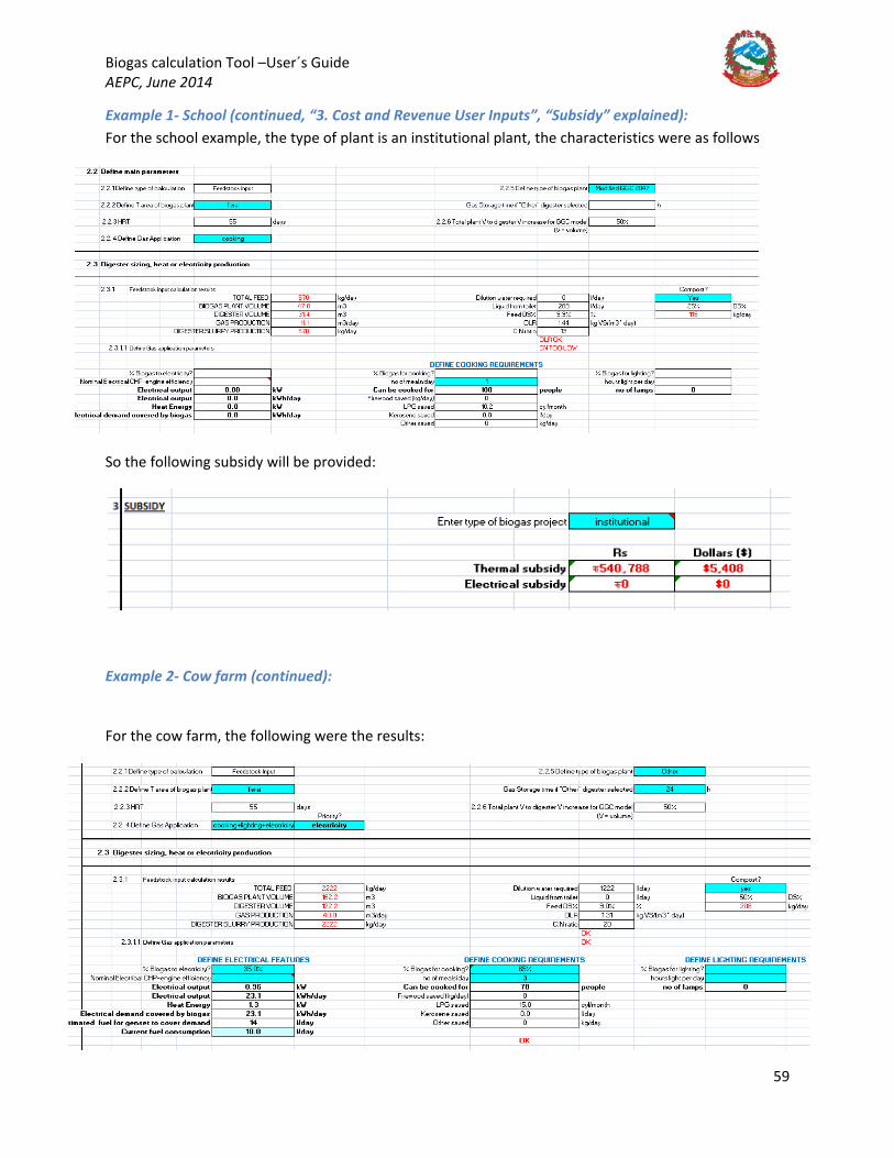
Biogas calculation Tool –User´s Guide AEPC, June 2014
59
Example 1- School (continued, “3. Cost and Revenue User Inputs”, “Subsidy” explained): For the school example, the type of plant is an institutional plant, the characteristics were as follows
So the following subsidy will be provided:
Example 2- Cow farm (continued):
For the cow farm, the following were the results:
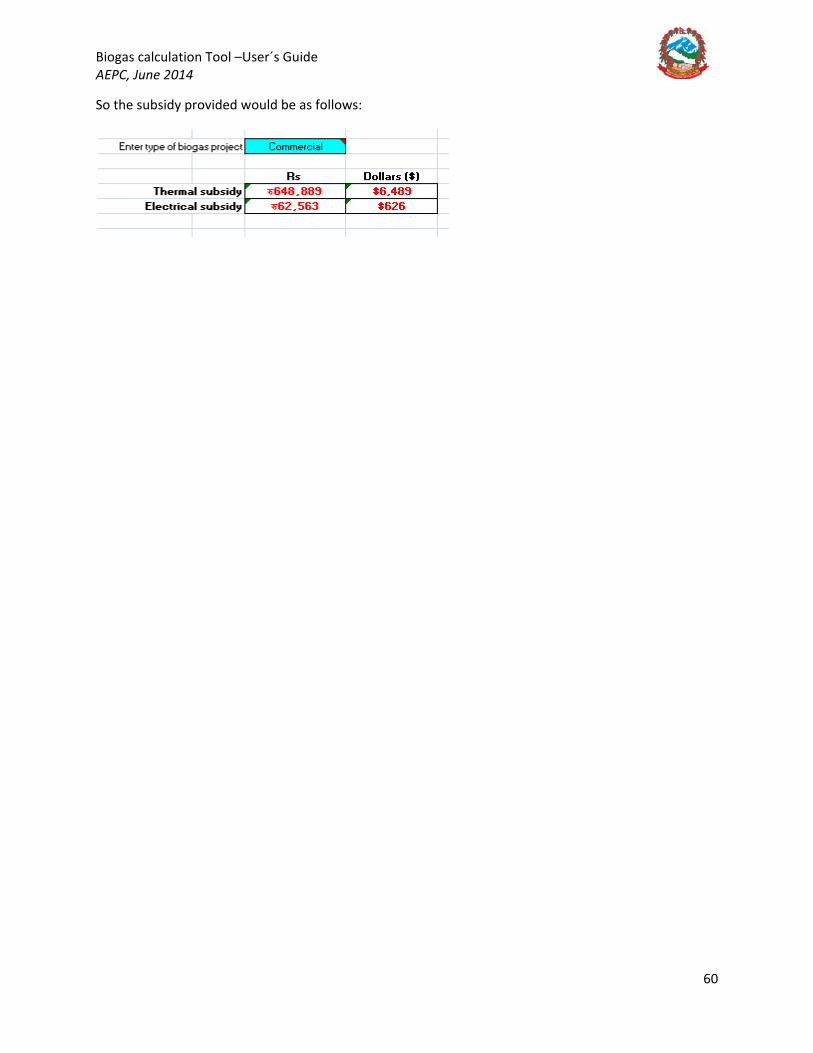
Biogas calculation Tool –User´s Guide AEPC, June 2014
60
So the subsidy provided would be as follows:
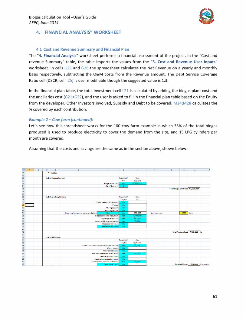
Biogas calculation Tool –User´s Guide AEPC, June 2014
61
4. FINANCIAL ANALYSIS” WORKSHEET
4.1 Cost and Revenue Summary and Financial Plan The “4. Financial Analysis” worksheet performs a financial assessment of the project. In the “Cost and revenue Summary” table, the table imports the values from the “3. Cost and Revenue User Inputs” worksheet. In cells G25 and G26 the spreadsheet calculates the Net Revenue on a yearly and monthly basis respectively, subtracting the O&M costs from the Revenue amount. The Debt Service Coverage Ratio cell (DSCR, cell I25) is user modifiable though the suggested value is 1.3.
In the financial plan table, the total investment cell L21 is calculated by adding the biogas plant cost and the ancillaries cost (G21+G22), and the user is asked to fill in the financial plan table based on the Equity from the developer, Other Investors involved, Subsidy and Debt to be covered. M24:M28 calculates the % covered by each contribution.
Example 2 – Cow farm (continued): Let´s see how this spreadsheet works for the 100 cow farm example in which 35% of the total biogas produced is used to produce electricity to cover the demand from the site, and 15 LPG cylinders per month are covered.
Assuming that the costs and savings are the same as in the section above, shown below:

Biogas calculation Tool –User´s Guide AEPC, June 2014
62

Biogas calculation Tool –User´s Guide AEPC, June 2014
63
The subsidy being:
Now everything has been defined for the Financial Analysis. In the “4. Financial Analysis” worksheet the user shall enter the own equity that the developer is prepared to contribute with to the project. Let´s say the farmer confirms that he will contribute with 400,000 Rs, and that, to finance the gap between the Total Investment and equity plus the subsidy, he will be happy to take up a loan. The debt to be considered is calculated as the difference between the Total Investment – (Equity + Other Investors + Subsidy). The first section of the “4. Financial Analysis” worksheet will look as follows:
4.2 Loan Amortisation and Cash Flow The first thing the user shall enter is the interest rate % in G33, followed by the number of years to repay the loan and the number of payments per year in G34 and G35 respectively. In this section, the spreadsheet will bring up a message on cell H34, based on the DSCR, describing whether the “Monthly loan payment” exceeds the “Maximum loan payment permissible amount”, which will not make the project qualify for a loan (the “𝑀𝑀𝐵𝐵𝑛𝑛𝑤𝑤ℎ𝑦𝑦𝑦𝑦 𝐿𝐿𝐵𝐵𝐵𝐵𝑛𝑛 𝑃𝑃𝐵𝐵𝑦𝑦𝑚𝑚𝑦𝑦𝑛𝑛𝑤𝑤” ∗ 𝐴𝐴𝑉𝑉𝐶𝐶𝑂𝑂 cannot be above the “Maximum loan payment permissible amount34
). Let´s see it in our example:
If the loan is to be repaid in 2 years, for instance, the spreadsheet will show, for a 12% interest rate and 12 payments per year, the following:
This is because, the “monthly loan payment” is higher than “the maximum loan payment permissible”, which is defined as the Net revenue divided by the DSCR (G38=G26/I25). Therefore, if we follow the
34 This is a requirement from the banks for projects to qualify for loans.
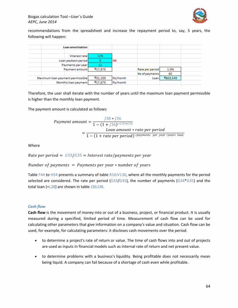
Biogas calculation Tool –User´s Guide AEPC, June 2014
64
recommendations from the spreadsheet and increase the repayment period to, say, 5 years, the following will happen:
Therefore, the user shall iterate with the number of years until the maximum loan payment permissible is higher than the monthly loan payment.
The payment amount is calculated as follows:
𝑃𝑃𝐵𝐵𝑦𝑦𝑚𝑚𝑦𝑦𝑛𝑛𝑤𝑤 𝐵𝐵𝑚𝑚𝐵𝐵𝑛𝑛𝑛𝑛𝑤𝑤 =𝑀𝑀38 ∗ 𝑀𝑀36
1 − (1 + 𝑀𝑀36)−𝐺𝐺35∗𝐺𝐺34
=𝐿𝐿𝐵𝐵𝐵𝐵𝑛𝑛 𝐵𝐵𝑚𝑚𝐵𝐵𝑛𝑛𝑛𝑛𝑤𝑤 ∗ 𝑛𝑛𝐵𝐵𝑤𝑤𝑦𝑦 𝑝𝑝𝑦𝑦𝑛𝑛 𝑝𝑝𝑦𝑦𝑛𝑛𝐵𝐵𝐵𝐵𝑦𝑦
1 − (1 + 𝑛𝑛𝐵𝐵𝑤𝑤𝑦𝑦 𝑝𝑝𝑦𝑦𝑛𝑛 𝑝𝑝𝑦𝑦𝑛𝑛𝐵𝐵𝐵𝐵𝑦𝑦)−𝑝𝑝𝐵𝐵𝑦𝑦𝑚𝑚𝑦𝑦𝑛𝑛𝑤𝑤𝐵𝐵 𝑝𝑝𝑦𝑦𝑛𝑛 𝑦𝑦𝑦𝑦𝐵𝐵𝑛𝑛 ∗𝑦𝑦𝑦𝑦𝐵𝐵𝑛𝑛𝐵𝐵 𝑦𝑦𝐵𝐵𝐵𝐵𝑛𝑛
Where
𝑂𝑂𝐵𝐵𝑤𝑤𝑦𝑦 𝑝𝑝𝑦𝑦𝑛𝑛 𝑝𝑝𝑦𝑦𝑛𝑛𝐵𝐵𝐵𝐵𝑦𝑦 = 𝐺𝐺33/𝐺𝐺35 = 𝐼𝐼𝑛𝑛𝑤𝑤𝑦𝑦𝑛𝑛𝑦𝑦𝐵𝐵𝑤𝑤 𝑛𝑛𝐵𝐵𝑤𝑤𝑦𝑦/𝑝𝑝𝐵𝐵𝑦𝑦𝑚𝑚𝑦𝑦𝑛𝑛𝑤𝑤𝐵𝐵 𝑝𝑝𝑦𝑦𝑛𝑛 𝑦𝑦𝑦𝑦𝐵𝐵𝑛𝑛
𝑁𝑁𝑛𝑛𝑚𝑚𝑛𝑛𝑦𝑦𝑛𝑛 𝐵𝐵𝑜𝑜 𝑝𝑝𝐵𝐵𝑦𝑦𝑚𝑚𝑦𝑦𝑛𝑛𝑤𝑤𝐵𝐵 = 𝑃𝑃𝐵𝐵𝑦𝑦𝑚𝑚𝑦𝑦𝑛𝑛𝑤𝑤𝐵𝐵 𝑝𝑝𝑦𝑦𝑛𝑛 𝑦𝑦𝑦𝑦𝐵𝐵𝑛𝑛 ∗ 𝑛𝑛𝑛𝑛𝑚𝑚𝑛𝑛𝑦𝑦𝑛𝑛 𝐵𝐵𝑜𝑜 𝑦𝑦𝑦𝑦𝐵𝐵𝑛𝑛𝐵𝐵
Table F44 to H54 presents a summary of table R10:V130, where all the monthly payments for the period selected are considered. The rate per period (G33/G35), the number of payments (G34*G35) and the total loan (=L28) are shown in table J36:J38.
Cash flow Cash flow is the movement of money into or out of a business, project, or financial product. It is usually measured during a specified, limited period of time. Measurement of cash flow can be used for calculating other parameters that give information on a company's value and situation. Cash flow can be used, for example, for calculating parameters: it discloses cash movements over the period.
• to determine a project's rate of return or value. The time of cash flows into and out of projects are used as inputs in financial models such as internal rate of return and net present value.
• to determine problems with a business's liquidity. Being profitable does not necessarily mean being liquid. A company can fail because of a shortage of cash even while profitable.
Biogas calculation Tool –User´s Guide AEPC, June 2014
65
• as an alternative measure of a business's profits when it is believed that accrual accounting concepts do not represent economic realities. For instance, a company may be notionally profitable but generating little operational cash (as may be the case for a company that barters its products rather than selling for cash). In such a case, the company may be deriving additional operating cash by issuing shares or raising additional debt finance.
• cash flow can be used to evaluate the 'quality' of income generated by accrual accounting. When net income is composed of large non-cash items it is considered low quality.
• to evaluate the risks within a financial product, e.g., matching cash requirements, evaluating default risk, re-investment requirements, etc.
Cash flow notion is based loosely on cash flow statement accounting standards. It's flexible as it can refer to time intervals spanning over past-future. It can refer to the total of all flows involved or a subset of those flows. Subset terms include net cash flow, operating cash flow and free cash flow.
Cash flows in the Financial Analysis worksheet are calculated as follows:
𝐿𝐿43 = 𝑌𝑌𝑦𝑦𝐵𝐵𝑛𝑛 0 = −(𝐺𝐺21 + 𝐺𝐺22 − (𝐿𝐿26 + 𝐿𝐿27))= − (𝐵𝐵𝐵𝐵𝐵𝐵𝐵𝐵𝐵𝐵𝐵𝐵 𝑝𝑝𝑦𝑦𝐵𝐵𝑛𝑛𝑤𝑤 𝑖𝑖𝐵𝐵𝐵𝐵𝑤𝑤 + 𝐴𝐴𝑛𝑛𝑖𝑖𝐵𝐵𝑦𝑦𝑦𝑦𝐵𝐵𝑛𝑛𝑦𝑦 𝐶𝐶𝐵𝐵𝐵𝐵𝑤𝑤𝐵𝐵 − (𝑤𝑤ℎ𝑦𝑦𝑛𝑛𝑚𝑚𝐵𝐵𝑦𝑦 𝐵𝐵𝑛𝑛𝑛𝑛𝐵𝐵𝐵𝐵𝑦𝑦𝑦𝑦+ 𝑦𝑦𝑦𝑦𝑦𝑦𝑖𝑖𝑤𝑤𝑛𝑛𝐵𝐵𝑖𝑖𝐵𝐵𝑦𝑦 𝐵𝐵𝑛𝑛𝑛𝑛𝐵𝐵𝐵𝐵𝑦𝑦𝑦𝑦)
The rest of the years:
𝑌𝑌𝑦𝑦𝐵𝐵𝑛𝑛 1 = $𝐺𝐺$24 − $𝐺𝐺$23 − 𝐹𝐹44 = 𝑂𝑂𝑦𝑦𝑅𝑅𝑦𝑦𝑛𝑛𝑛𝑛𝑦𝑦 − 𝑂𝑂&𝑀𝑀 𝑖𝑖𝐵𝐵𝐵𝐵𝑤𝑤 – 𝐿𝐿𝐵𝐵𝐵𝐵𝑛𝑛 𝑝𝑝𝐵𝐵𝑦𝑦𝑚𝑚𝑦𝑦𝑛𝑛𝑤𝑤 𝑌𝑌𝑦𝑦𝐵𝐵𝑛𝑛 1
And so on for the rest of the period.
For the example of the cow farm, the table will look as follows:
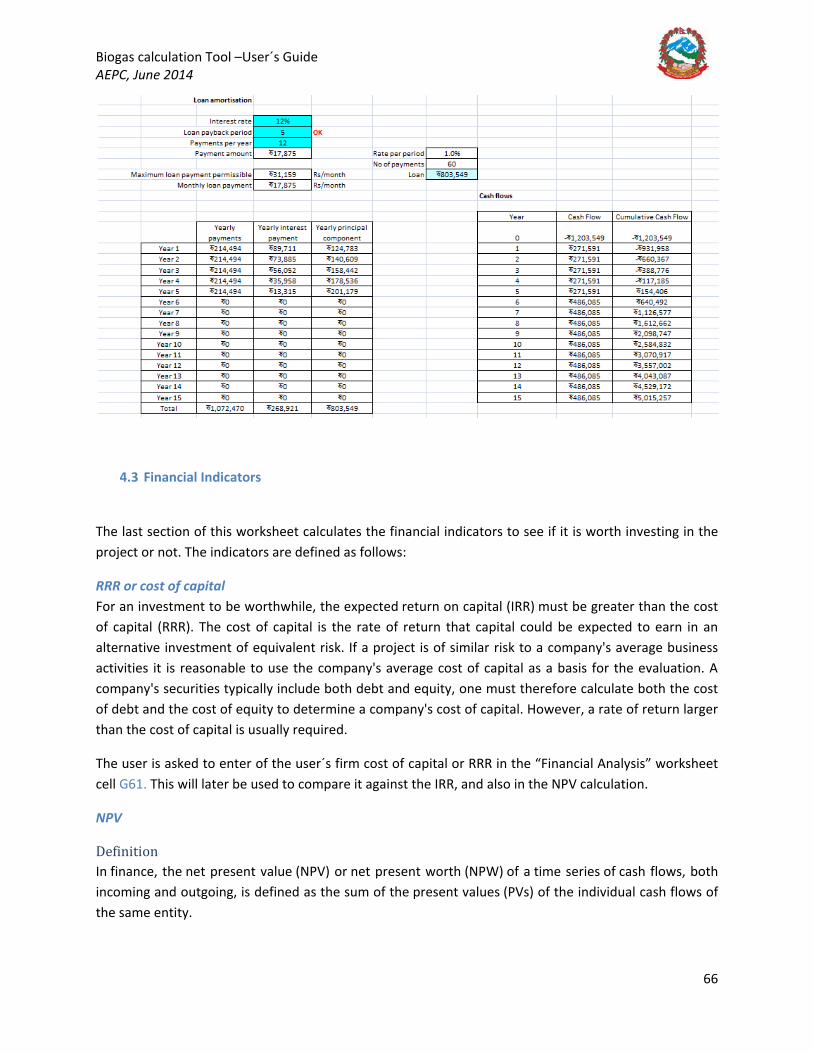
Biogas calculation Tool –User´s Guide AEPC, June 2014
66
4.3 Financial Indicators
The last section of this worksheet calculates the financial indicators to see if it is worth investing in the project or not. The indicators are defined as follows:
RRR or cost of capital For an investment to be worthwhile, the expected return on capital (IRR) must be greater than the cost of capital (RRR). The cost of capital is the rate of return that capital could be expected to earn in an alternative investment of equivalent risk. If a project is of similar risk to a company's average business activities it is reasonable to use the company's average cost of capital as a basis for the evaluation. A company's securities typically include both debt and equity, one must therefore calculate both the cost of debt and the cost of equity to determine a company's cost of capital. However, a rate of return larger than the cost of capital is usually required.
The user is asked to enter of the user´s firm cost of capital or RRR in the “Financial Analysis” worksheet cell G61. This will later be used to compare it against the IRR, and also in the NPV calculation.
NPV
Definition In finance, the net present value (NPV) or net present worth (NPW) of a time series of cash flows, both incoming and outgoing, is defined as the sum of the present values (PVs) of the individual cash flows of the same entity.

Biogas calculation Tool –User´s Guide AEPC, June 2014
67
In the case when all future cash flows are incoming and the only outflow of cash is the purchase price, the NPV is simply the PV of future cash flows minus the purchase price (which is its own PV). NPV is a central tool in discounted cash flow (DCF) analysis and is a standard method for using the time value of money to appraise long-term projects. Used for capital budgeting and widely used throughout economics, finance, and accounting, it measures the excess or shortfall of cash flows, in present value terms, above the cost of funds.
NPV can be described as the “difference amount” between the sums of discounted: cash inflows and cash outflows. It compares the present value of money today to the present value of money in the future, taking inflation and returns into account
The NPV of a sequence of cash flows takes as input the cash flows and a discount rate or discount curve and outputs a price.
Each cash inflow/outflow is discounted back to its present value (PV). Then they are summed. Therefore NPV is the sum of all terms,
where
– the time of the cash flow
– the discount rate (the rate of return that could be earned on an investment in the financial markets with similar risk.); the opportunity cost of capital
– the net cash flow i.e. cash inflow – cash outflow, at time t . For educational purposes, is commonly placed to the left of the sum to emphasize its role as (minus) the investment.
The result of this formula is multiplied with the Annual Net cash in-flows and reduced by Initial Cash outlay the present value but in cases where the cash flows are not equal in amount, then the previous formula will be used to determine the present value of each cash flow separately. Any cash flow within 12 months will not be discounted for NPV purpose, nevertheless the usual initial investments during the first year R0are summed up a negative cash flow.[2]
Given the (period, cash flow) pairs ( , ) where is the total number of periods, the net present value is given by:

Biogas calculation Tool –User´s Guide AEPC, June 2014
68
Discount rate A firm's weighted average cost of capital (after tax) is often used, but many people believe that it is appropriate to use higher discount rates to adjust for risk, opportunity cost, or other factors. A variable discount rate with higher rates applied to cash flows occurring further along the time span might be used to reflect the yield curve premium for long-term debt.
An approach to choosing the discount rate factor is to decide the rate which the capital needed for the project could return if invested in an alternative venture. If, for example, the capital required for Project A can earn 5% elsewhere, use this discount rate in the NPV calculation to allow a direct comparison to be made between Project A and the alternative. Related to this concept is to use the firm's reinvestment rate. Reinvestment rate can be defined as the rate of return for the firm's investments on average. When analyzing projects in a capital constrained environment, it may be appropriate to use the reinvestment rate rather than the firm's weighted average cost of capital as the discount factor. It reflects opportunity cost of investment, rather than the possibly lower cost of capital.
To some extent, the selection of the discount rate is dependent on the use to which it will be put. If the intent is simply to determine whether a project will add value to the company, using the firm's weighted average cost of capital may be appropriate. If trying to decide between alternative investments in order to maximize the value of the firm, the corporate reinvestment rate would probably be a better choice.
For the “Financial Analysis” worksheet, the RRR needs to be input for the NPV calculation. The period of time would be that of the loan repayment period.
Use in decision making NPV is an indicator of how much value an investment or project adds to the firm. With a particular
project, if is a positive value, the project is in the status of positive cash inflow in the time of t.
If is a negative value, the project is in the status of discounted cash outflow in the time of t. Appropriately risked projects with a positive NPV could be accepted. This does not necessarily mean that they should be undertaken since NPV at the cost of capital may not account for opportunity cost, i.e., comparison with other available investments. In financial theory, if there is a choice between two mutually exclusive alternatives, the one yielding the higher NPV should be selected.
If... It means... Then...
NPV > 0
the investment would add value to the firm
the project may be accepted
NPV < 0
the investment would subtract value from the firm
the project should be rejected
NPV the investment would neither gain nor lose
We should be indifferent in the decision whether to accept or reject the project. This project adds no monetary value. Decision should be based
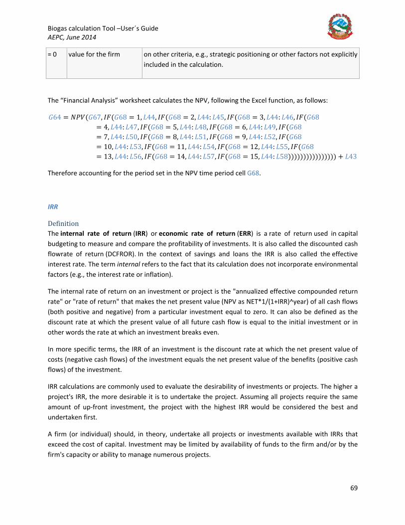
Biogas calculation Tool –User´s Guide AEPC, June 2014
69
= 0 value for the firm on other criteria, e.g., strategic positioning or other factors not explicitly included in the calculation.
The “Financial Analysis” worksheet calculates the NPV, following the Excel function, as follows:
𝐺𝐺64 = 𝑁𝑁𝑃𝑃𝑉𝑉(𝐺𝐺67, 𝐼𝐼𝐹𝐹(𝐺𝐺68 = 1, 𝐿𝐿44, 𝐼𝐼𝐹𝐹(𝐺𝐺68 = 2, 𝐿𝐿44: 𝐿𝐿45, 𝐼𝐼𝐹𝐹(𝐺𝐺68 = 3, 𝐿𝐿44: 𝐿𝐿46, 𝐼𝐼𝐹𝐹(𝐺𝐺68= 4, 𝐿𝐿44: 𝐿𝐿47, 𝐼𝐼𝐹𝐹(𝐺𝐺68 = 5, 𝐿𝐿44: 𝐿𝐿48, 𝐼𝐼𝐹𝐹(𝐺𝐺68 = 6, 𝐿𝐿44: 𝐿𝐿49, 𝐼𝐼𝐹𝐹(𝐺𝐺68= 7, 𝐿𝐿44: 𝐿𝐿50, 𝐼𝐼𝐹𝐹(𝐺𝐺68 = 8, 𝐿𝐿44: 𝐿𝐿51, 𝐼𝐼𝐹𝐹(𝐺𝐺68 = 9, 𝐿𝐿44: 𝐿𝐿52, 𝐼𝐼𝐹𝐹(𝐺𝐺68= 10, 𝐿𝐿44: 𝐿𝐿53, 𝐼𝐼𝐹𝐹(𝐺𝐺68 = 11, 𝐿𝐿44: 𝐿𝐿54, 𝐼𝐼𝐹𝐹(𝐺𝐺68 = 12, 𝐿𝐿44: 𝐿𝐿55, 𝐼𝐼𝐹𝐹(𝐺𝐺68= 13, 𝐿𝐿44: 𝐿𝐿56, 𝐼𝐼𝐹𝐹(𝐺𝐺68 = 14, 𝐿𝐿44: 𝐿𝐿57, 𝐼𝐼𝐹𝐹(𝐺𝐺68 = 15, 𝐿𝐿44: 𝐿𝐿58)))))))))))))))) + 𝐿𝐿43
Therefore accounting for the period set in the NPV time period cell G68.
IRR
Definition The internal rate of return (IRR) or economic rate of return (ERR) is a rate of return used in capital budgeting to measure and compare the profitability of investments. It is also called the discounted cash flowrate of return (DCFROR). In the context of savings and loans the IRR is also called the effective interest rate. The term internal refers to the fact that its calculation does not incorporate environmental factors (e.g., the interest rate or inflation).
The internal rate of return on an investment or project is the "annualized effective compounded return rate" or "rate of return" that makes the net present value (NPV as NET*1/(1+IRR)^year) of all cash flows (both positive and negative) from a particular investment equal to zero. It can also be defined as the discount rate at which the present value of all future cash flow is equal to the initial investment or in other words the rate at which an investment breaks even.
In more specific terms, the IRR of an investment is the discount rate at which the net present value of costs (negative cash flows) of the investment equals the net present value of the benefits (positive cash flows) of the investment.
IRR calculations are commonly used to evaluate the desirability of investments or projects. The higher a project's IRR, the more desirable it is to undertake the project. Assuming all projects require the same amount of up-front investment, the project with the highest IRR would be considered the best and undertaken first.
A firm (or individual) should, in theory, undertake all projects or investments available with IRRs that exceed the cost of capital. Investment may be limited by availability of funds to the firm and/or by the firm's capacity or ability to manage numerous projects.

Biogas calculation Tool –User´s Guide AEPC, June 2014
70
Uses of IRR Because the internal rate of return is a rate quantity, it is an indicator of the efficiency, quality, or yield of an investment. This is in contrast with the net present value, which is an indicator of the value or magnitude of an investment.
An investment is considered acceptable if its internal rate of return is greater than an established minimum acceptable rate of return or cost of capital. In a scenario where an investment is considered by a firm that has equity holders, this minimum rate is the cost of capital of the investment (which may be determined by the risk-adjusted cost of capital of alternative investments). This ensures that the investment is supported by equity holders since, in general, an investment whose IRR exceeds its cost of capital adds value for the company (i.e., it is economically profitable).
The rate of return that equates the present value of a project’s cash inflows with the present value of its cash outflows i.e. it sets out the net present value equal to zero. Internal rate of return is basically used to measure the efficiency of capital investment. Internal rate of return is generally required low cost of capital to accept the project.
Calculation Given a collection of pairs (time, cash flow) involved in a project, the internal rate of return follows from the net present value as a function of the rate of return. A rate of return for which this function is zero is an internal rate of return.
Given the (period, cash flow) pairs ( , ) where is a positive integer, the total number of periods , and the net present value , the internal rate of return is given by in:
The period is usually given in years, but the calculation may be made simpler if is calculated using the period in which the majority of the problem is defined (e.g., using months if most of the cash flows occur at monthly intervals) and converted to a yearly period thereafter.
Any fixed time can be used in place of the present (e.g., the end of one interval of an annuity); the value obtained is zero if and only if the NPV is zero.
In the case that the cash flows are random variables, such as in the case of a life annuity, the expected values are put into the above formula.
Often, the value of cannot be found analytically. In this case, numerical methods or graphical methods must be used.
The “Financial Analysis” worksheet calculates the IRR, with the Excel function, as follows:
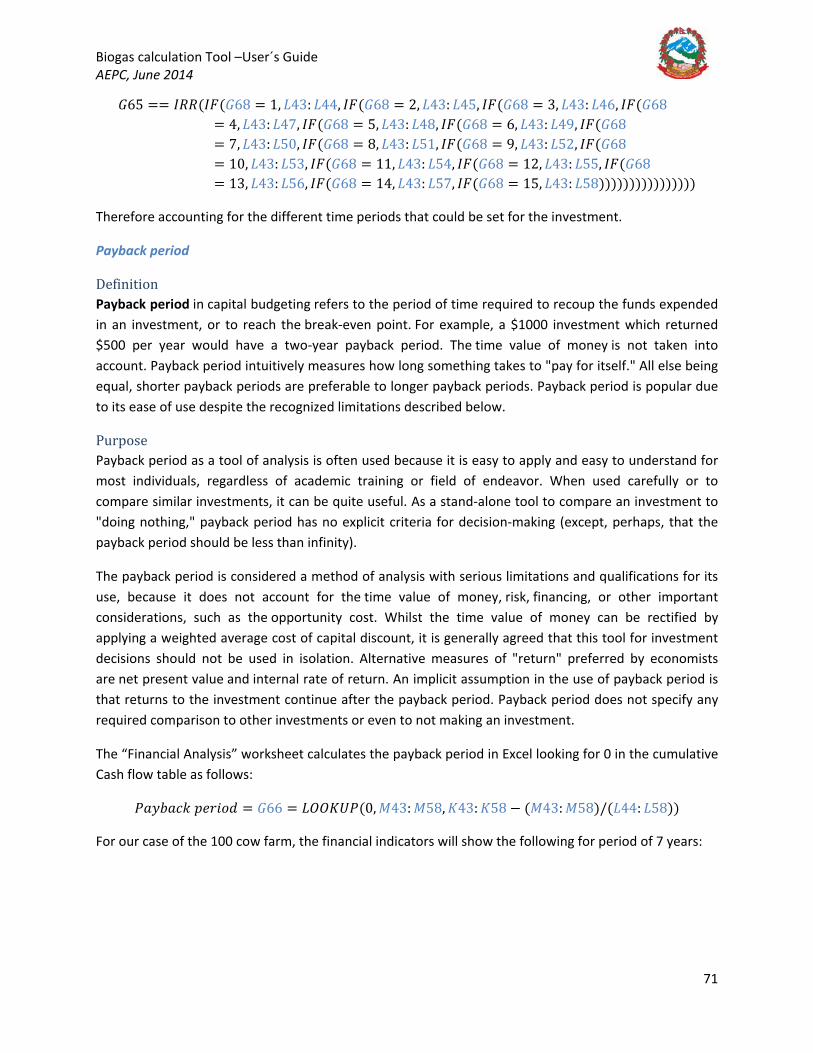
Biogas calculation Tool –User´s Guide AEPC, June 2014
71
𝐺𝐺65 == 𝐼𝐼𝑂𝑂𝑂𝑂(𝐼𝐼𝐹𝐹(𝐺𝐺68 = 1, 𝐿𝐿43: 𝐿𝐿44, 𝐼𝐼𝐹𝐹(𝐺𝐺68 = 2, 𝐿𝐿43: 𝐿𝐿45, 𝐼𝐼𝐹𝐹(𝐺𝐺68 = 3, 𝐿𝐿43: 𝐿𝐿46, 𝐼𝐼𝐹𝐹(𝐺𝐺68= 4, 𝐿𝐿43: 𝐿𝐿47, 𝐼𝐼𝐹𝐹(𝐺𝐺68 = 5, 𝐿𝐿43: 𝐿𝐿48, 𝐼𝐼𝐹𝐹(𝐺𝐺68 = 6, 𝐿𝐿43: 𝐿𝐿49, 𝐼𝐼𝐹𝐹(𝐺𝐺68= 7, 𝐿𝐿43: 𝐿𝐿50, 𝐼𝐼𝐹𝐹(𝐺𝐺68 = 8, 𝐿𝐿43: 𝐿𝐿51, 𝐼𝐼𝐹𝐹(𝐺𝐺68 = 9, 𝐿𝐿43: 𝐿𝐿52, 𝐼𝐼𝐹𝐹(𝐺𝐺68= 10, 𝐿𝐿43: 𝐿𝐿53, 𝐼𝐼𝐹𝐹(𝐺𝐺68 = 11, 𝐿𝐿43: 𝐿𝐿54, 𝐼𝐼𝐹𝐹(𝐺𝐺68 = 12, 𝐿𝐿43: 𝐿𝐿55, 𝐼𝐼𝐹𝐹(𝐺𝐺68= 13, 𝐿𝐿43: 𝐿𝐿56, 𝐼𝐼𝐹𝐹(𝐺𝐺68 = 14, 𝐿𝐿43: 𝐿𝐿57, 𝐼𝐼𝐹𝐹(𝐺𝐺68 = 15, 𝐿𝐿43: 𝐿𝐿58))))))))))))))))
Therefore accounting for the different time periods that could be set for the investment.
Payback period
Definition Payback period in capital budgeting refers to the period of time required to recoup the funds expended in an investment, or to reach the break-even point. For example, a $1000 investment which returned $500 per year would have a two-year payback period. The time value of money is not taken into account. Payback period intuitively measures how long something takes to "pay for itself." All else being equal, shorter payback periods are preferable to longer payback periods. Payback period is popular due to its ease of use despite the recognized limitations described below.
Purpose Payback period as a tool of analysis is often used because it is easy to apply and easy to understand for most individuals, regardless of academic training or field of endeavor. When used carefully or to compare similar investments, it can be quite useful. As a stand-alone tool to compare an investment to "doing nothing," payback period has no explicit criteria for decision-making (except, perhaps, that the payback period should be less than infinity).
The payback period is considered a method of analysis with serious limitations and qualifications for its use, because it does not account for the time value of money, risk, financing, or other important considerations, such as the opportunity cost. Whilst the time value of money can be rectified by applying a weighted average cost of capital discount, it is generally agreed that this tool for investment decisions should not be used in isolation. Alternative measures of "return" preferred by economists are net present value and internal rate of return. An implicit assumption in the use of payback period is that returns to the investment continue after the payback period. Payback period does not specify any required comparison to other investments or even to not making an investment.
The “Financial Analysis” worksheet calculates the payback period in Excel looking for 0 in the cumulative Cash flow table as follows:
𝑃𝑃𝐵𝐵𝑦𝑦𝑛𝑛𝐵𝐵𝑖𝑖𝑘𝑘 𝑝𝑝𝑦𝑦𝑛𝑛𝐵𝐵𝐵𝐵𝑦𝑦 = 𝐺𝐺66 = 𝐿𝐿𝑂𝑂𝑂𝑂𝐾𝐾𝑈𝑈𝑃𝑃(0, 𝑀𝑀43: 𝑀𝑀58, 𝐾𝐾43: 𝐾𝐾58 − (𝑀𝑀43: 𝑀𝑀58)/(𝐿𝐿44: 𝐿𝐿58))
For our case of the 100 cow farm, the financial indicators will show the following for period of 7 years:

Biogas calculation Tool –User´s Guide AEPC, June 2014
72
So the project is not worth investing into, even though the monthly loan repayments would have been lower than the maximum loan payment permissible. So let´s consider a longer loan tenure period of, say, for instance, 10 years, and paying back the loan in 5 years:
Now, the project financial indicators, NPV and IRR would have favoured investing in the project:

Biogas calculation Tool –User´s Guide AEPC, June 2014
73
APPENDIX A: “APP. MB AND PRETREATMENT” AND “APP. FEEDSTOCK INPUT” WORKSHEETS
“App. MB and Pretreatment” Worksheet The main function of this worksheet is to perform a Mass Balance (MB) and determine whether there is a need for a thickening stage, or considering other alternatives such as DEWATS plants (or disregard the treatment of toilet waste altogether) if the feedstock is too diluted or for dilution water if the feedstock is too thick for proper digestion to occur.
The only requirements from the user in this worksheet are to check Step 1: Define toilet parameters, as explained in Example 1 under the “2. User Inputs and Results” worksheet above. The user would have defined whether toilet waste is treated and the type of toilet used on site in Population table in the “2. User Inputs and Results” worksheet as follows:
Then the user would have to check and modify, if required, the recommended values in the yellow filled cells in the “App. MB and Pretreatment” worksheet:
The urine value is from literature, whereas the flushing water for auto and pour flush toilets are assumed, same as the number of visits to the toilet. 9% DS is recommended by BSP Nepal as the feed DS% for good mixing and digestion performance in the digestion while minimizing dilution water requirements.
The following parameters, maximum and minimum values, can also be modified by the user. This parameters are used to determine the need or otherwise of a settlement stage or dilution water as explained below. Continuing with Example 1 of the school principal:
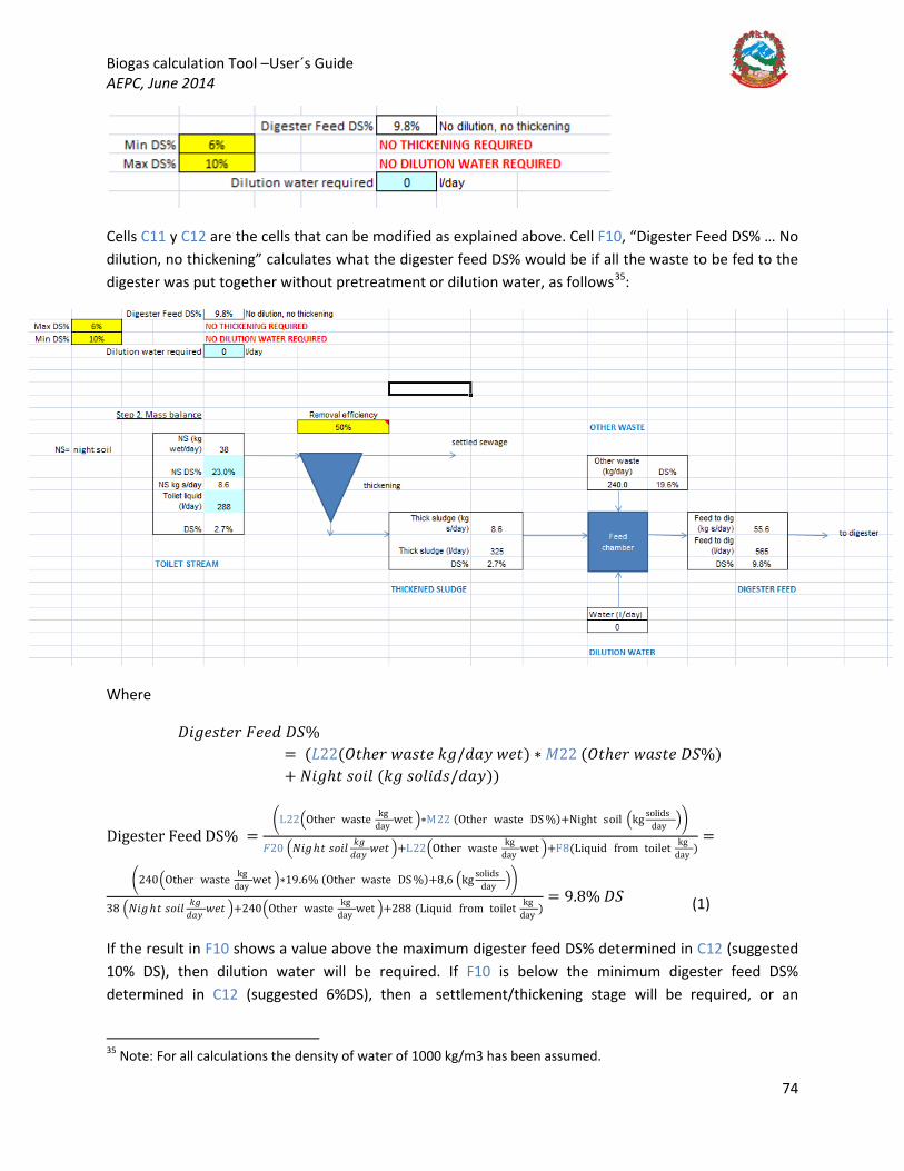
Biogas calculation Tool –User´s Guide AEPC, June 2014
74
Cells C11 y C12 are the cells that can be modified as explained above. Cell F10, “Digester Feed DS% … No dilution, no thickening” calculates what the digester feed DS% would be if all the waste to be fed to the digester was put together without pretreatment or dilution water, as follows35
Where
𝐴𝐴𝐵𝐵𝐵𝐵𝑦𝑦𝐵𝐵𝑤𝑤𝑦𝑦𝑛𝑛 𝐹𝐹𝑦𝑦𝑦𝑦𝑦𝑦 𝐴𝐴𝑉𝑉% = (𝐿𝐿22(𝑂𝑂𝑤𝑤ℎ𝑦𝑦𝑛𝑛 𝑤𝑤𝐵𝐵𝐵𝐵𝑤𝑤𝑦𝑦 𝑘𝑘𝐵𝐵/𝑦𝑦𝐵𝐵𝑦𝑦 𝑤𝑤𝑦𝑦𝑤𝑤) ∗ 𝑀𝑀22 (𝑂𝑂𝑤𝑤ℎ𝑦𝑦𝑛𝑛 𝑤𝑤𝐵𝐵𝐵𝐵𝑤𝑤𝑦𝑦 𝐴𝐴𝑉𝑉%) + 𝑁𝑁𝐵𝐵𝐵𝐵ℎ𝑤𝑤 𝐵𝐵𝐵𝐵𝐵𝐵𝑦𝑦 (𝑘𝑘𝐵𝐵 𝐵𝐵𝐵𝐵𝑦𝑦𝐵𝐵𝑦𝑦𝐵𝐵/𝑦𝑦𝐵𝐵𝑦𝑦))
Digester Feed DS% =�L22�Other waste kg
day wet �∗M22 (Other waste DS %)+Night soil �kg solidsday ��
𝐹𝐹20 �𝑁𝑁𝐵𝐵𝐵𝐵 ℎ𝑤𝑤 𝐵𝐵𝐵𝐵𝐵𝐵𝑦𝑦 𝑘𝑘𝐵𝐵𝑦𝑦𝐵𝐵𝑦𝑦 𝑤𝑤𝑦𝑦𝑤𝑤 �+L22�Other waste kg
day wet �+F8(Liquid from toilet kgday )
=
�240�Other waste kgday wet �∗19.6% (Other waste DS %)+8,6 �kg solids
day ��
38 �𝑁𝑁𝐵𝐵𝐵𝐵 ℎ𝑤𝑤 𝐵𝐵𝐵𝐵𝐵𝐵𝑦𝑦 𝑘𝑘𝐵𝐵𝑦𝑦𝐵𝐵𝑦𝑦 𝑤𝑤𝑦𝑦𝑤𝑤 �+240�Other waste kg
day wet �+288 (Liquid from toilet kgday )
= 9.8% 𝐴𝐴𝑉𝑉
:
(1)
If the result in F10 shows a value above the maximum digester feed DS% determined in C12 (suggested 10% DS), then dilution water will be required. If F10 is below the minimum digester feed DS% determined in C12 (suggested 6%DS), then a settlement/thickening stage will be required, or an
35 Note: For all calculations the density of water of 1000 kg/m3 has been assumed.

Biogas calculation Tool –User´s Guide AEPC, June 2014
75
alternative technology such as DEWATS or other. The user would have selected which option is used when the feed is too dilute in cell G40 of the “2. User Inputs and Results” worksheet.
If F10 is above 6%, it is considered that although the feed will be slightly diluted, a settlement/thickening stage is unlikely to be required.
The liquid from toilet, which needs to be calculated to see whether the feed will be diluted enough (so no dilution water needs to be added) or whether it is too diluted so that it needs to be thickened or other alternatives such as DEWATS considered, is calculated as follows (depending on the type of toilet, which determines how much water is flushed and on the number of shifts, which determines how many visits to the toilet are made per person, and on the population equivalent):
Liquid from toilet � lday
� =′ User inputs and results′ ! G32 (population equivalent night soil) ∗
⎝
⎜⎛
IF �User inputs and results′ ! K25(number of shifts) =
2,F3(lurinehdday),IF′User inputs and results′!K25=1,F3(lurinehdday)2+IF′User inputs and results′!K25number of shifts=2,F6(visits to toilet),IF′User inputs and results′!K25number of shifts=1,F6(visits to toilet)2∗IFUser inputs and results′!K29type of toilet=Auto flush,F4(auto flushing waterlflush(,IFUser inputs and results′!K29type of toilet=Pour flush,F5(pour flushing water, l/flush (2)
The first mass balance is done in the thickening stage, where 50% of solids are assumed as captured in the thickened sludge, and the thickened sludge stream is calculated (wet and DS%) so the final feed to the digester is 9% DS (suggested, can be changed by the user). In our case, the feed is just between the limits so, as can be seen in the image above, the following messages will appear: “NO THICKENING REQUIRED” and “NO DILUTION REQUIRED” in cells F11 and F12.
It is worth noting that if the user selects “No thickening (DEWATS or other)” in cell G40 of the “2. User Inputs and Results worksheet”, this thickening stage will be bypassed.
Let´s have a look at the individual streams of the thickening stage mass balance:

Biogas calculation Tool –User´s Guide AEPC, June 2014
76
TOILET STREAM: cell F20 is the total wet kg/day of night soil produced as per the per capita production defined in the “Waste characterization” worksheet (0.3 kg/hd/day suggested) multiplied by the population equivalent (which depends on the number of shifts at the institution, as explained in the “2. User Inputs and Results” worksheet). This calculation takes place in the “App. Feedstock Input” worksheet. In our case,
𝑇𝑇𝑂𝑂𝐼𝐼𝐿𝐿𝐷𝐷𝑇𝑇 𝑉𝑉𝑇𝑇𝑂𝑂𝐷𝐷𝐴𝐴𝑀𝑀 𝑁𝑁𝑉𝑉 �𝑘𝑘𝐵𝐵 𝑤𝑤𝑦𝑦𝑤𝑤𝑦𝑦𝐵𝐵𝑦𝑦
� = 125 (𝑝𝑝𝐵𝐵𝑝𝑝𝑛𝑛𝑦𝑦𝐵𝐵𝑤𝑤𝐵𝐵𝐵𝐵𝑛𝑛 𝑦𝑦𝑒𝑒𝑛𝑛𝐵𝐵𝑅𝑅𝐵𝐵𝑦𝑦𝑦𝑦𝑛𝑛𝑤𝑤) ∗ (0.3 𝑘𝑘𝐵𝐵/ℎ𝑦𝑦/𝑦𝑦𝐵𝐵𝑦𝑦) = 38 𝑘𝑘𝐵𝐵/𝑦𝑦𝐵𝐵𝑦𝑦.
The DS% in cell F21 comes from the assumptions in the “1. Waste Char. + Energy Demand” worksheet. F22 is the dry mass per day calculated as follows:
𝐹𝐹22 = 𝑇𝑇𝑂𝑂𝐼𝐼𝐿𝐿𝐷𝐷𝑇𝑇 𝑉𝑉𝑇𝑇𝑂𝑂𝐷𝐷𝐴𝐴𝑀𝑀 𝐷𝐷𝑦𝑦𝑤𝑤 𝑚𝑚𝐵𝐵𝐵𝐵𝐵𝐵 �𝑘𝑘𝐵𝐵
𝑦𝑦𝐵𝐵𝑦𝑦� ∗ 𝐴𝐴𝑉𝑉% = 𝐹𝐹21 ∗ 𝐹𝐹20 = 38
𝑘𝑘𝐵𝐵𝑦𝑦𝐵𝐵𝑦𝑦
∗ 23%𝐴𝐴𝑉𝑉
= 8.6 𝑘𝑘𝐵𝐵 𝐵𝐵/𝑦𝑦𝐵𝐵𝑦𝑦
The final DS% is calculated by dividing the kg of solids by the addition of the toilet water and the kg of wet solids:
𝑇𝑇𝑂𝑂𝐼𝐼𝐿𝐿𝐷𝐷𝑇𝑇 𝑉𝑉𝑇𝑇𝑂𝑂𝐷𝐷𝐴𝐴𝑀𝑀 𝐴𝐴𝑉𝑉% = 𝐹𝐹24 = 𝐹𝐹22𝐹𝐹23+𝐹𝐹20
= 𝑁𝑁𝑉𝑉 𝑘𝑘𝐵𝐵 𝐵𝐵/𝑦𝑦𝐵𝐵𝑦𝑦
𝑇𝑇𝐵𝐵𝐵𝐵𝑦𝑦𝑦𝑦𝑤𝑤 𝑦𝑦𝐵𝐵𝑒𝑒𝑛𝑛𝐵𝐵𝑦𝑦 𝑦𝑦𝑦𝑦𝐵𝐵𝑦𝑦 +𝑁𝑁𝑉𝑉 𝑘𝑘𝐵𝐵 𝑤𝑤𝑦𝑦𝑤𝑤 /𝑦𝑦𝐵𝐵𝑦𝑦
= 8.6 𝑘𝑘𝐵𝐵 𝐵𝐵/𝑦𝑦𝐵𝐵𝑦𝑦
288 𝑦𝑦𝑦𝑦𝐵𝐵𝑦𝑦 +38 𝑘𝑘𝐵𝐵 𝑤𝑤𝑦𝑦𝑤𝑤 /𝑦𝑦𝐵𝐵𝑦𝑦
=
2.7% 𝐴𝐴𝑉𝑉.
THICKENED SLUDGE: if no thickening is required, or if the user selects “No thickening (DEWATS or other)” in cell G40 of the “2. User Inputs and Results worksheet”, then this stream will be equal to the TOILET STREAM (as in our case and shown in the picture above). If thickening is required, the user can determine a solids removal efficiency in cell H19. This value is recommended as 50%, which means that 50% of the solids will go to the THICKENED SLUDGE stream and the rest to the settled sewage stream. Therefore, the thickened sludge solids of the thickened sludge stream will be:
𝑇𝑇ℎ𝐵𝐵𝑖𝑖𝑘𝑘 𝐵𝐵𝑦𝑦𝑛𝑛𝑦𝑦𝐵𝐵𝑦𝑦 �𝑘𝑘𝐵𝐵𝐵𝐵
𝑦𝑦𝐵𝐵𝑦𝑦� = 𝐹𝐹22 �𝑘𝑘𝐵𝐵
𝐵𝐵𝐵𝐵𝑦𝑦𝐵𝐵𝑦𝑦𝐵𝐵𝑦𝑦𝐵𝐵𝑦𝑦
𝐵𝐵𝑛𝑛 𝑇𝑇𝑂𝑂𝐼𝐼𝐿𝐿𝐷𝐷𝑇𝑇 𝑉𝑉𝑇𝑇𝑂𝑂𝐷𝐷𝐴𝐴𝑀𝑀� ∗ 𝐻𝐻19 (% 𝑛𝑛𝑦𝑦𝑚𝑚𝐵𝐵𝑅𝑅𝐵𝐵𝑦𝑦 𝑦𝑦𝑜𝑜𝑜𝑜𝐵𝐵𝑖𝑖𝐵𝐵𝑦𝑦𝑛𝑛𝑖𝑖𝑦𝑦)
The thickened sludge wet component of the thickened sludge stream is a bit trickier. This is calculated so as to make it achieve the “Target DS%” feed to the digester (cell F7, in our case 9% DS), and comes out of a mass balance to the feed chamber, fixing the DS% to be that of F7.
In the feed chamber, all OTHER WASTE (OW)36
36 OTHER WASTE: sum of all waste other than night soil. It comes from the “App. Feedstock Input” worksheet, where each animal´s waste production is multiplied by the number of animals (L22). The DS% as calculated as a % contribution on a mass basis from each animal and the particular DS% from each type of waste as defined in the “1. Waste Char. + Energy Demand” worksheet (M22).
other than night soil is mixed night soil (THICKENED SLUDGE (TS) stream) and dilution water if required (DILUTION WATER (DW)) to make up the DIGESTER FEED. Let´s assume that X is the proportion of solids in each stream. The equations are as follows:
Biogas calculation Tool –User´s Guide AEPC, June 2014
77
The dry solids mass balance:
(𝑂𝑂𝐷𝐷)𝑋𝑋𝐵𝐵𝑤𝑤 + (𝑇𝑇𝑉𝑉)𝑋𝑋𝑤𝑤𝐵𝐵 + (𝐴𝐴𝐷𝐷)𝑋𝑋𝑦𝑦𝑤𝑤 = (𝐴𝐴𝐹𝐹)𝑋𝑋𝑦𝑦𝑜𝑜 (3)
Where (DW)*Xdw = 0 as no solids are present in the dilution water stream, and from where:
(𝑇𝑇𝑉𝑉)𝑋𝑋𝑤𝑤𝐵𝐵 +(𝑂𝑂𝐷𝐷)𝑋𝑋𝐵𝐵𝑤𝑤𝑋𝑋𝑦𝑦𝑜𝑜
= (𝐴𝐴𝐹𝐹) (4)
The overall wet mass balance is:
(𝑂𝑂𝐷𝐷) + (𝑇𝑇𝑉𝑉) + (𝐴𝐴𝐷𝐷) = (𝐴𝐴𝐹𝐹), from where: (𝑇𝑇𝑉𝑉) = (𝐴𝐴𝐹𝐹) − ((𝑂𝑂𝐷𝐷) + (𝐴𝐴𝐷𝐷)) (5)
Substituting the equation for DF above into the last one, then:
(𝑇𝑇𝑉𝑉) = (𝑇𝑇𝑉𝑉)𝑋𝑋𝑤𝑤𝐵𝐵 +(𝑂𝑂𝐷𝐷)𝑋𝑋𝐵𝐵𝑤𝑤𝑋𝑋𝑦𝑦𝑜𝑜
− �(𝑂𝑂𝐷𝐷) + (𝐴𝐴𝐷𝐷)� = 𝑀𝑀24+𝐿𝐿22∗𝑀𝑀22𝐹𝐹7
− 𝐿𝐿22) 37
(𝑂𝑂𝐷𝐷) + (𝑇𝑇𝑉𝑉) + (𝐴𝐴𝐷𝐷) = (𝐴𝐴𝐹𝐹), from where: (𝐴𝐴𝐷𝐷) = (𝐴𝐴𝐹𝐹) − ((𝑂𝑂𝐷𝐷) + (𝑇𝑇𝑉𝑉)) (7)
Replacing with DF as per (3) above, we obtain:
(6)
By fixing Xdf (the DS% in the digester feed) to the “target DS%” (9% DS recommended), then the TOILET STREAM will always be such as to make the target DS% for the digester feed. In practice this may be achieved by modifying the desludging regime (time that the desludging valve in the settlement tank is opened) to achieve the DS% set in cell J26, which is calculated as J24/J25.
DILUTION WATER: This stream is calculated similarly to the THICKENED SLUDGE stream, from the same mass balance. Dilution water is required for whenever F10 (what the feed to the digester would be if no thickening/settlement or dilution water was added to the raw feed) is above the maximum DS% set in C12 allowed to feed the digester. In practice, dilution water will always be required for projects in which the dilution cannot be achieved by the TOILET STREAM or THICKENED SLUDGE stream (i.e. where the toilet stream is too thick or no toilet waste is treated – only animal feedstock or other waste that makes F10 above C12).
Same as for the THICKENED SLUDGE stream, the DILUTION WATER stream is calculated so as to make the final feed DS% to the digester the same as the target DS% specified in cell F7.
(𝐴𝐴𝐷𝐷) = (𝑇𝑇𝑉𝑉)𝑋𝑋𝑤𝑤𝐵𝐵 +(𝑂𝑂𝐷𝐷)𝑋𝑋𝐵𝐵𝑤𝑤𝑋𝑋𝑦𝑦𝑜𝑜
− �(𝑂𝑂𝐷𝐷) + (𝑇𝑇𝑉𝑉)� = 𝑀𝑀24+𝐿𝐿22∗𝑀𝑀22𝐹𝐹7
− (𝐿𝐿22 + 𝑀𝑀25) (8)
DIGESTER FEED: As all other parameters in the thickened sludge and dilution water streams have been fixed to ensure a digester feed DS% equal to the target DS% in F10, this stream is just a result of the mass balance as follows:
37 It is assumed that no dilution water is required if the sludge has had to be thickened as the toilet waste will have sufficient liquid to dilute the total mixture to the target DS% for the digester feed.

Biogas calculation Tool –User´s Guide AEPC, June 2014
78
𝑂𝑂24 = (𝐴𝐴𝐹𝐹)𝑋𝑋𝑦𝑦𝑜𝑜 = (𝑇𝑇𝑉𝑉)𝑋𝑋𝑤𝑤𝐵𝐵 + (𝑂𝑂𝐷𝐷)𝑋𝑋𝐵𝐵𝑤𝑤 = 𝑀𝑀24 + 𝐿𝐿22 ∗ 𝑀𝑀22 (9)
𝑂𝑂25 = (𝐴𝐴𝐹𝐹) = (𝑂𝑂𝐷𝐷) + (𝑇𝑇𝑉𝑉) + (𝐴𝐴𝐷𝐷) = 𝐿𝐿22 + 𝐿𝐿31 + 𝑀𝑀25 (10)
(𝑋𝑋𝑦𝑦𝑜𝑜) = 𝑋𝑋𝑦𝑦𝑜𝑜 (𝐴𝐴𝐹𝐹)𝐴𝐴𝐹𝐹
= 𝑂𝑂24𝑂𝑂25
(11)
The DIGESTER FEED calculated as per the procedure above is what will be used elsewhere in the worksheet to calculate Total Digester Volumes in the “App. Feedstock Input” worksheet (cell E58) and the “Demand and App. Feedstock Input” worksheet (cell E103).
But let´s see this in an example to illustrate the operation of this worksheet:
Example 1 (School - continued): Going back to our school example, this was the data available.
As it can be seen on the population table, it recommends that no thickening and no dilution water are required. This means that the mixture of toilet waste (with its inherent liquid) and other waste (in this case, pig and cow dung) are within the parameters defined in the “App. MB and Pretreatment Worksheet”. Let´s have a look at this worksheet.
First, above are the parameters that the user has to check. As the toilet is a pour flush type of toilet, the suggestion is 1.2 l/flush, which the user could modify. Let´s assume this is accurate enough for the school toilets, same as the other parameters (which again, if better information is available, can be modified by the user).

Biogas calculation Tool –User´s Guide AEPC, June 2014
79
In this case, cell F10, “Digester Feed DS%, No dilution, no thickening”, returns a value of 9.8% DS. This is because F10, calculated as per equation (1) above, determines that mixing all other waste with toilet waste is within the specified 6-10% DS range in cells C11:C12.
Digester Feed DS%
=�240 � kg
day wet� ∗ M22 (Other waste DS%) + Night soil �kg solidsday ��
𝐹𝐹20 �𝑁𝑁𝐵𝐵𝐵𝐵ℎ𝑤𝑤 𝐵𝐵𝐵𝐵𝐵𝐵𝑦𝑦 𝑘𝑘𝐵𝐵𝑦𝑦𝐵𝐵𝑦𝑦 𝑤𝑤𝑦𝑦𝑤𝑤� + L22 �Other waste kg
day wet� + F8 �Liquid from toilet kgday�
=�240 �kitchen w, cow and pig kg
day wet� ∗ 19.6 (kitchen w, cow and pig DS%) + 8.6 �night soil kg solidsday ��
38 �𝑁𝑁𝐵𝐵𝐵𝐵ℎ𝑤𝑤 𝐵𝐵𝐵𝐵𝐵𝐵𝑦𝑦 𝑘𝑘𝐵𝐵𝑦𝑦𝐵𝐵𝑦𝑦 𝑤𝑤𝑦𝑦𝑤𝑤� + 245 �kitchen w, cow and pig kg
day wet� + 288 �Liquid from toilet kgday�
= 9.8% 𝐴𝐴𝑉𝑉
In this case, although the feed is not 9% DS as per the target DS% set in F7, the spreadsheet assumes that, when the range is within 6-10% DS, that is acceptable for the digester, assuming that this way no extra equipment is needed regarding dilution or thickening (in this case dilution water would have been required, but, in the case that the result would have been below 9% DS but above 6% DS, then a thickening stage would have been required to achieve the 9% DS feed to the digester. This, however, is disregarded in the calculation to avoid the extra unit costs). The messages that appear are “NO THICKENING REQUIRED” and “NO DILUTION REQUIRED” in cells F11 and F12. These cells later set what happens in the toilet stream and the dilution water. Let’s see how these messages are defined:
F11 =IF(C11<F10,"NO THICKENING REQUIRED","THICKENING REQUIRED")
F12 = IF(F10>C12,"DILUTION WATER REQUIRED","NO DILUTION WATER REQUIRED")
Therefore, they are comparing F10 at the minimum and maximum values set in C11 and C12, and, since it’s within the range specified, saying that neither thickening nor dilution water are specified.
These values affect the THICKENED SLUDGE and the DILUTION WATER streams as follows:
THICKENED SLUDGE:
𝑇𝑇ℎ𝐵𝐵𝑖𝑖𝑘𝑘𝑦𝑦𝑛𝑛𝑦𝑦𝑦𝑦 𝐵𝐵𝑦𝑦𝑛𝑛𝑦𝑦𝐵𝐵𝑦𝑦 𝑘𝑘𝐵𝐵 𝐵𝐵/𝑦𝑦𝐵𝐵𝑦𝑦 = 𝑀𝑀24 = 𝐼𝐼𝐹𝐹(𝐹𝐹11 = "𝑁𝑁𝐵𝐵 𝑇𝑇ℎ𝐵𝐵𝑖𝑖𝑘𝑘𝑦𝑦𝑛𝑛𝐵𝐵𝑛𝑛𝐵𝐵 𝑛𝑛𝑦𝑦𝑒𝑒𝑛𝑛𝐵𝐵𝑛𝑛𝑦𝑦𝑦𝑦", 𝐹𝐹22, 𝐹𝐹22 ∗ 𝐻𝐻19)
𝑇𝑇ℎ𝐵𝐵𝑖𝑖𝑘𝑘𝑦𝑦𝑛𝑛𝑦𝑦𝑦𝑦 𝐵𝐵𝑦𝑦𝑛𝑛𝑦𝑦𝐵𝐵𝑦𝑦 𝑦𝑦/𝑦𝑦𝐵𝐵𝑦𝑦 (𝑘𝑘𝐵𝐵 𝑤𝑤𝑦𝑦𝑤𝑤) = 𝑀𝑀25 = 𝐼𝐼𝐹𝐹(𝐹𝐹11= "𝑁𝑁𝐵𝐵 𝑤𝑤ℎ𝐵𝐵𝑖𝑖𝑘𝑘𝑦𝑦𝑛𝑛𝐵𝐵𝑛𝑛𝐵𝐵 𝑛𝑛𝑦𝑦𝑒𝑒𝑛𝑛𝐵𝐵𝑛𝑛𝑦𝑦𝑦𝑦", 𝐹𝐹23+ 𝐹𝐹20, 𝐼𝐼𝐹𝐹(′𝑈𝑈𝐵𝐵𝑦𝑦𝑛𝑛 𝐵𝐵𝑛𝑛𝑝𝑝𝑛𝑛𝑤𝑤𝐵𝐵 𝐵𝐵𝑛𝑛𝑦𝑦 𝑛𝑛𝑦𝑦𝐵𝐵𝑛𝑛𝑦𝑦𝑤𝑤𝐵𝐵′! 𝐺𝐺32= 0,0, (𝑀𝑀24 + 𝐿𝐿22 ∗ 𝑀𝑀22)/𝐹𝐹7 − 𝐿𝐿22))
This means that if “No thickening is required”, then TOILET STREAM = THICKENED SLUDGE stream. Otherwise, the mass balance as per the procedure above is performed.
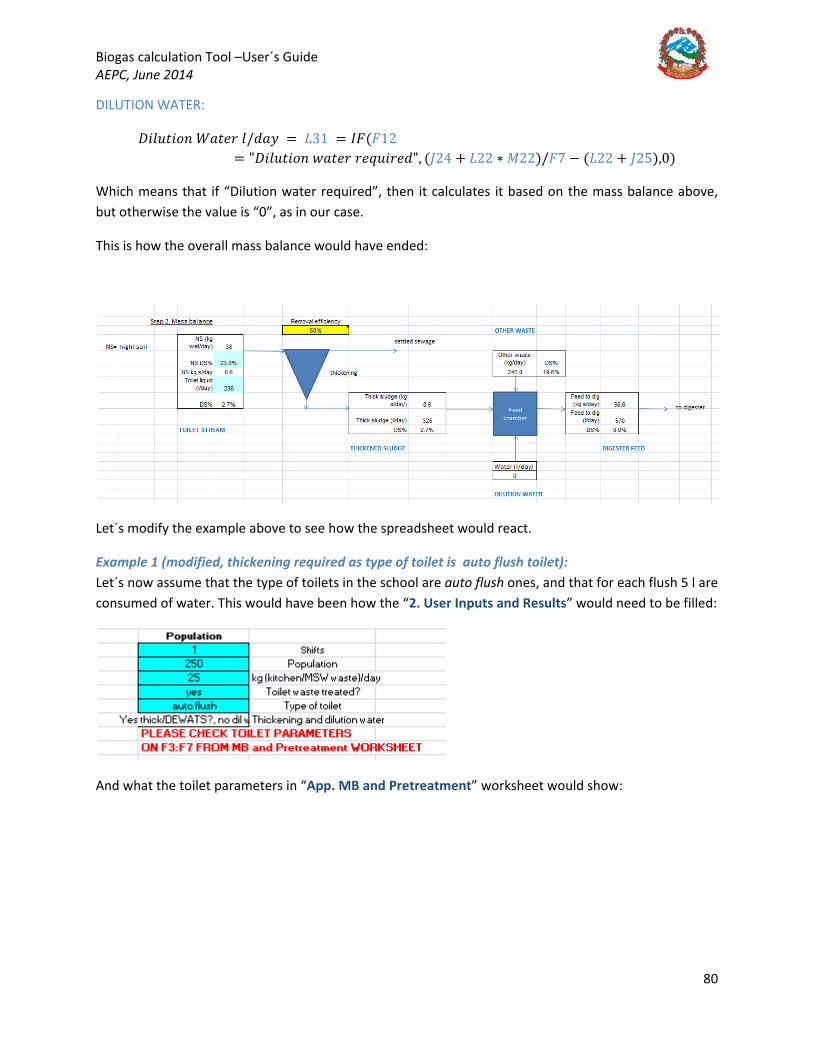
Biogas calculation Tool –User´s Guide AEPC, June 2014
80
DILUTION WATER:
𝐴𝐴𝐵𝐵𝑦𝑦𝑛𝑛𝑤𝑤𝐵𝐵𝐵𝐵𝑛𝑛 𝐷𝐷𝐵𝐵𝑤𝑤𝑦𝑦𝑛𝑛 𝑦𝑦/𝑦𝑦𝐵𝐵𝑦𝑦 = 𝐿𝐿31 = 𝐼𝐼𝐹𝐹(𝐹𝐹12= "𝐴𝐴𝐵𝐵𝑦𝑦𝑛𝑛𝑤𝑤𝐵𝐵𝐵𝐵𝑛𝑛 𝑤𝑤𝐵𝐵𝑤𝑤𝑦𝑦𝑛𝑛 𝑛𝑛𝑦𝑦𝑒𝑒𝑛𝑛𝐵𝐵𝑛𝑛𝑦𝑦𝑦𝑦", (𝑀𝑀24 + 𝐿𝐿22 ∗ 𝑀𝑀22)/𝐹𝐹7 − (𝐿𝐿22 + 𝑀𝑀25),0)
Which means that if “Dilution water required”, then it calculates it based on the mass balance above, but otherwise the value is “0”, as in our case.
This is how the overall mass balance would have ended:
Let´s modify the example above to see how the spreadsheet would react.
Example 1 (modified, thickening required as type of toilet is auto flush toilet): Let´s now assume that the type of toilets in the school are auto flush ones, and that for each flush 5 l are consumed of water. This would have been how the “2. User Inputs and Results” would need to be filled:
And what the toilet parameters in “App. MB and Pretreatment” worksheet would show:
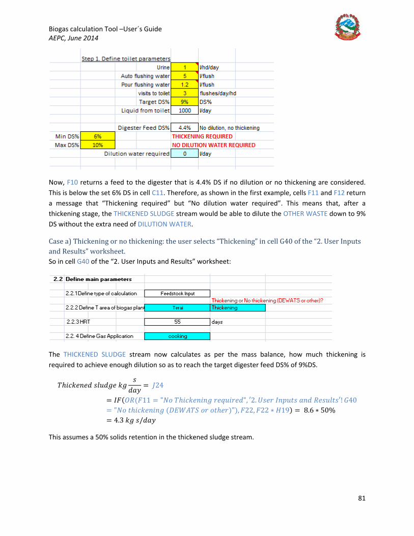
Biogas calculation Tool –User´s Guide AEPC, June 2014
81
Now, F10 returns a feed to the digester that is 4.4% DS if no dilution or no thickening are considered. This is below the set 6% DS in cell C11. Therefore, as shown in the first example, cells F11 and F12 return a message that “Thickening required” but “No dilution water required”. This means that, after a thickening stage, the THICKENED SLUDGE stream would be able to dilute the OTHER WASTE down to 9% DS without the extra need of DILUTION WATER.
Case a) Thickening or no thickening: the user selects “Thickening” in cell G40 of the “2. User Inputs and Results” worksheet. So in cell G40 of the “2. User Inputs and Results” worksheet:
The THICKENED SLUDGE stream now calculates as per the mass balance, how much thickening is required to achieve enough dilution so as to reach the target digester feed DS% of 9%DS.
𝑇𝑇ℎ𝐵𝐵𝑖𝑖𝑘𝑘𝑦𝑦𝑛𝑛𝑦𝑦𝑦𝑦 𝐵𝐵𝑦𝑦𝑛𝑛𝑦𝑦𝐵𝐵𝑦𝑦 𝑘𝑘𝐵𝐵𝐵𝐵
𝑦𝑦𝐵𝐵𝑦𝑦= 𝑀𝑀24
= 𝐼𝐼𝐹𝐹(𝑂𝑂𝑂𝑂(𝐹𝐹11 = "𝑁𝑁𝐵𝐵 𝑇𝑇ℎ𝐵𝐵𝑖𝑖𝑘𝑘𝑦𝑦𝑛𝑛𝐵𝐵𝑛𝑛𝐵𝐵 𝑛𝑛𝑦𝑦𝑒𝑒𝑛𝑛𝐵𝐵𝑛𝑛𝑦𝑦𝑦𝑦", ′2. 𝑈𝑈𝐵𝐵𝑦𝑦𝑛𝑛 𝐼𝐼𝑛𝑛𝑝𝑝𝑛𝑛𝑤𝑤𝐵𝐵 𝐵𝐵𝑛𝑛𝑦𝑦 𝑂𝑂𝑦𝑦𝐵𝐵𝑛𝑛𝑦𝑦𝑤𝑤𝐵𝐵′! 𝐺𝐺40= "𝑁𝑁𝐵𝐵 𝑤𝑤ℎ𝐵𝐵𝑖𝑖𝑘𝑘𝑦𝑦𝑛𝑛𝐵𝐵𝑛𝑛𝐵𝐵 (𝐴𝐴𝐷𝐷𝐷𝐷𝐴𝐴𝑇𝑇𝑉𝑉 𝐵𝐵𝑛𝑛 𝐵𝐵𝑤𝑤ℎ𝑦𝑦𝑛𝑛)"), 𝐹𝐹22, 𝐹𝐹22 ∗ 𝐻𝐻19) = 8.6 ∗ 50%= 4.3 𝑘𝑘𝐵𝐵 𝐵𝐵/𝑦𝑦𝐵𝐵𝑦𝑦
This assumes a 50% solids retention in the thickened sludge stream.

Biogas calculation Tool –User´s Guide AEPC, June 2014
82
𝑇𝑇ℎ𝐵𝐵𝑖𝑖𝑘𝑘𝑦𝑦𝑛𝑛𝑦𝑦𝑦𝑦 𝐵𝐵𝑦𝑦𝑛𝑛𝑦𝑦𝐵𝐵𝑦𝑦 𝑦𝑦/𝑦𝑦𝐵𝐵𝑦𝑦 (𝑘𝑘𝐵𝐵 𝑤𝑤𝑦𝑦𝑤𝑤) = 𝑀𝑀25 = 𝐼𝐼𝐹𝐹((𝑂𝑂𝑂𝑂(𝐹𝐹11= "𝑁𝑁𝐵𝐵 𝑇𝑇ℎ𝐵𝐵𝑖𝑖𝑘𝑘𝑦𝑦𝑛𝑛𝐵𝐵𝑛𝑛𝐵𝐵 𝑛𝑛𝑦𝑦𝑒𝑒𝑛𝑛𝐵𝐵𝑛𝑛𝑦𝑦𝑦𝑦", ′2. 𝑈𝑈𝐵𝐵𝑦𝑦𝑛𝑛 𝐼𝐼𝑛𝑛𝑝𝑝𝑛𝑛𝑤𝑤𝐵𝐵 𝐵𝐵𝑛𝑛𝑦𝑦 𝑂𝑂𝑦𝑦𝐵𝐵𝑛𝑛𝑦𝑦𝑤𝑤𝐵𝐵′! 𝐺𝐺40= "𝑁𝑁𝐵𝐵 𝑤𝑤ℎ𝐵𝐵𝑖𝑖𝑘𝑘𝑦𝑦𝑛𝑛𝐵𝐵𝑛𝑛𝐵𝐵 (𝐴𝐴𝐷𝐷𝐷𝐷𝐴𝐴𝑇𝑇𝑉𝑉 𝐵𝐵𝑛𝑛 𝐵𝐵𝑤𝑤ℎ𝑦𝑦𝑛𝑛)"), 𝐹𝐹23+ 𝐹𝐹20, 𝐼𝐼𝐹𝐹(′2. 𝑈𝑈𝐵𝐵𝑦𝑦𝑛𝑛 𝐼𝐼𝑛𝑛𝑝𝑝𝑛𝑛𝑤𝑤𝐵𝐵 𝐵𝐵𝑛𝑛𝑦𝑦 𝑂𝑂𝑦𝑦𝐵𝐵𝑛𝑛𝑦𝑦𝑤𝑤𝐵𝐵′! 𝐺𝐺32 = 0,0, (𝑀𝑀24 + 𝐿𝐿22 ∗ 𝑀𝑀22)/𝐹𝐹7 − 𝐿𝐿22))= (4.3 𝑘𝑘𝐵𝐵 𝐵𝐵 𝐵𝐵𝑜𝑜 𝑁𝑁𝑉𝑉 + 245∗ 19.6% 𝑘𝑘𝐵𝐵 𝐵𝐵 𝐵𝐵𝑜𝑜 𝑖𝑖𝐵𝐵𝑤𝑤, 𝑝𝑝𝐵𝐵𝐵𝐵 𝐵𝐵𝑛𝑛𝑦𝑦 𝑘𝑘𝐵𝐵𝑤𝑤𝑖𝑖ℎ𝑦𝑦𝑛𝑛 𝑤𝑤𝐵𝐵𝐵𝐵𝑤𝑤𝑦𝑦)/9%𝐴𝐴𝑉𝑉 – 245 𝑘𝑘𝐵𝐵/𝑦𝑦𝐵𝐵𝑦𝑦 = 336 𝑦𝑦/𝑦𝑦𝐵𝐵𝑦𝑦. 38
This is mixed with the OTHER WASTE stream in the feed chamber, resulting in the DIGESTER FEED stream as calculated from the mass balance equations detailed above.
As it can be seen, the final DS% is 9%, which was always going to be the result as the THICKENED SLUDGE stream had been fixed to achieve this target DS% set in F7.
Case b) Thickening or no thickening: the user selects “No thickening (DEWATS or Other)” in cell G40 of the “2. User Inputs and Results” worksheet. So in cell G40 of the “2. User Inputs and Results” worksheet:
The THICKENED SLUDGE stream now is the same as the TOILET STREAM as the “No thickening (DEWATS or other) option has been selected.
38 Please note that density assumed that of water 1000 kg/m3 for all streams.

Biogas calculation Tool –User´s Guide AEPC, June 2014
83
𝑇𝑇ℎ𝐵𝐵𝑖𝑖𝑘𝑘𝑦𝑦𝑛𝑛𝑦𝑦𝑦𝑦 𝐵𝐵𝑦𝑦𝑛𝑛𝑦𝑦𝐵𝐵𝑦𝑦 𝑘𝑘𝐵𝐵 𝐵𝐵𝑦𝑦𝐵𝐵𝑦𝑦
= 𝑀𝑀24
= 𝐼𝐼𝐹𝐹(𝑂𝑂𝑂𝑂(𝐹𝐹11 = "𝑁𝑁𝐵𝐵 𝑇𝑇ℎ𝐵𝐵𝑖𝑖𝑘𝑘𝑦𝑦𝑛𝑛𝐵𝐵𝑛𝑛𝐵𝐵 𝑛𝑛𝑦𝑦𝑒𝑒𝑛𝑛𝐵𝐵𝑛𝑛𝑦𝑦𝑦𝑦", ′2. 𝑈𝑈𝐵𝐵𝑦𝑦𝑛𝑛 𝐼𝐼𝑛𝑛𝑝𝑝𝑛𝑛𝑤𝑤𝐵𝐵 𝐵𝐵𝑛𝑛𝑦𝑦 𝑂𝑂𝑦𝑦𝐵𝐵𝑛𝑛𝑦𝑦𝑤𝑤𝐵𝐵′! 𝐺𝐺40= "𝑁𝑁𝐵𝐵 𝑤𝑤ℎ𝐵𝐵𝑖𝑖𝑘𝑘𝑦𝑦𝑛𝑛𝐵𝐵𝑛𝑛𝐵𝐵 (𝐴𝐴𝐷𝐷𝐷𝐷𝐴𝐴𝑇𝑇𝑉𝑉 𝐵𝐵𝑛𝑛 𝐵𝐵𝑤𝑤ℎ𝑦𝑦𝑛𝑛)"), 𝐹𝐹22, 𝐹𝐹22 ∗ 𝐻𝐻19) = 8.6 𝑘𝑘𝐵𝐵 𝐵𝐵/𝑦𝑦𝐵𝐵𝑦𝑦
The overall mass balance would be:
Example 1 (modified, dilution water required if no toilet waste is treated): Let´s now assume that no toilet waste is being treated, therefore this stream cannot be used to dilute the cow and pig waste from our school.39
The answer to “Toilet waste treated” would be “No”. Let´s have a look at the “App. MB and Pretreatment” worksheet:
This will mean that dilution water is required.
In this case, the “2. User Inputs and Results” would have been as follows:
39 Even in the case that toilet waste was treated but the mixture with the other waste would give values above the maximum specified feed DS% to the digester in C12, the dilution water required would adjust to make up for the shortage in dilution in order to achieve the target DS% feed solids set in F7.
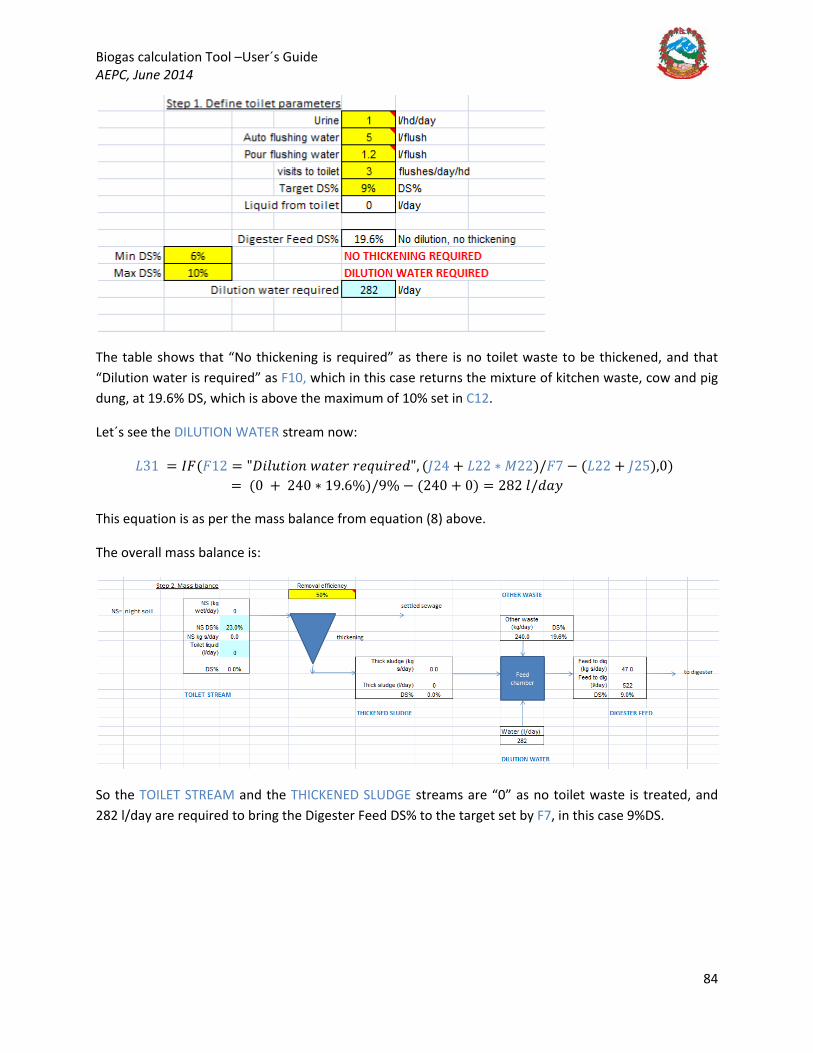
Biogas calculation Tool –User´s Guide AEPC, June 2014
84
The table shows that “No thickening is required” as there is no toilet waste to be thickened, and that “Dilution water is required” as F10, which in this case returns the mixture of kitchen waste, cow and pig dung, at 19.6% DS, which is above the maximum of 10% set in C12.
Let´s see the DILUTION WATER stream now:
𝐿𝐿31 = 𝐼𝐼𝐹𝐹(𝐹𝐹12 = "𝐴𝐴𝐵𝐵𝑦𝑦𝑛𝑛𝑤𝑤𝐵𝐵𝐵𝐵𝑛𝑛 𝑤𝑤𝐵𝐵𝑤𝑤𝑦𝑦𝑛𝑛 𝑛𝑛𝑦𝑦𝑒𝑒𝑛𝑛𝐵𝐵𝑛𝑛𝑦𝑦𝑦𝑦", (𝑀𝑀24 + 𝐿𝐿22 ∗ 𝑀𝑀22)/𝐹𝐹7 − (𝐿𝐿22 + 𝑀𝑀25),0) = (0 + 240 ∗ 19.6%)/9% − (240 + 0) = 282 𝑦𝑦/𝑦𝑦𝐵𝐵𝑦𝑦
This equation is as per the mass balance from equation (8) above.
The overall mass balance is:
So the TOILET STREAM and the THICKENED SLUDGE streams are “0” as no toilet waste is treated, and 282 l/day are required to bring the Digester Feed DS% to the target set by F7, in this case 9%DS.
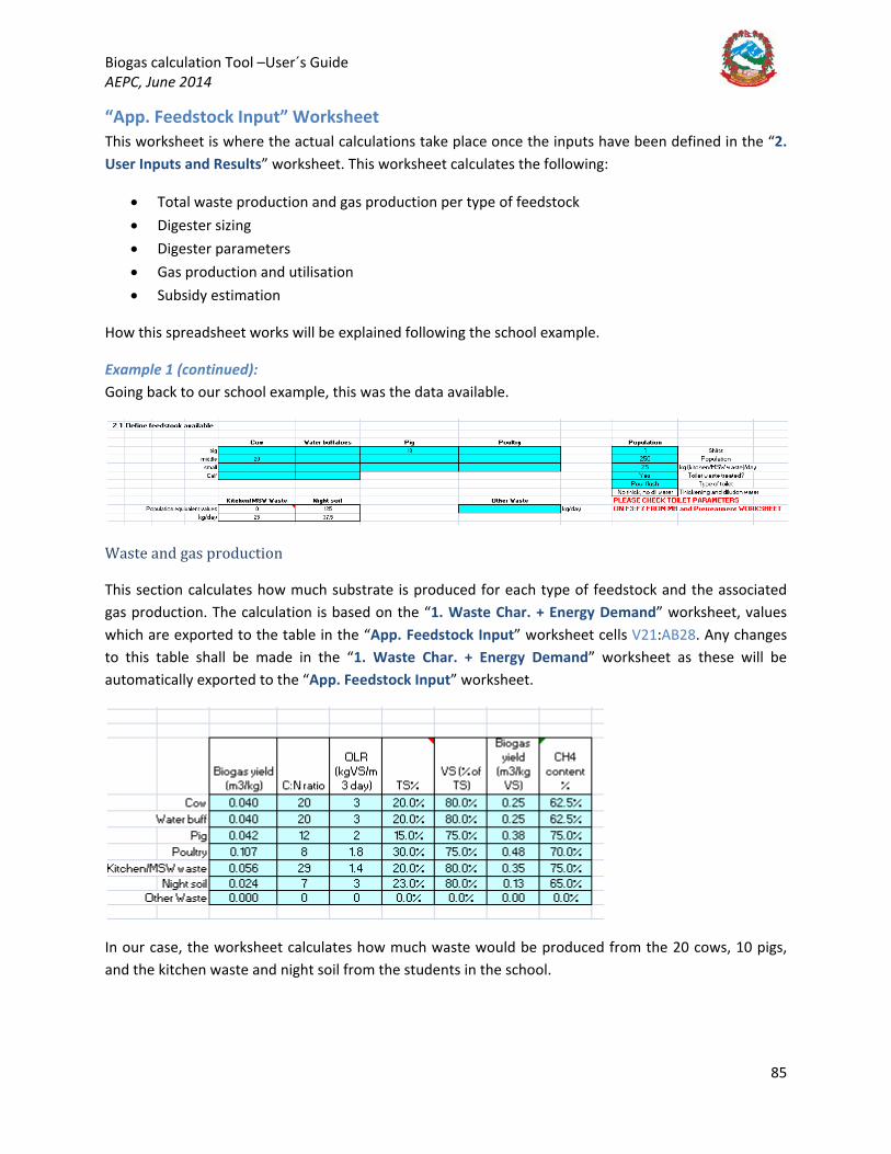
Biogas calculation Tool –User´s Guide AEPC, June 2014
85
“App. Feedstock Input” Worksheet This worksheet is where the actual calculations take place once the inputs have been defined in the “2. User Inputs and Results” worksheet. This worksheet calculates the following:
• Total waste production and gas production per type of feedstock • Digester sizing • Digester parameters • Gas production and utilisation • Subsidy estimation
How this spreadsheet works will be explained following the school example.
Example 1 (continued): Going back to our school example, this was the data available.
Waste and gas production
This section calculates how much substrate is produced for each type of feedstock and the associated gas production. The calculation is based on the “1. Waste Char. + Energy Demand” worksheet, values which are exported to the table in the “App. Feedstock Input” worksheet cells V21:AB28. Any changes to this table shall be made in the “1. Waste Char. + Energy Demand” worksheet as these will be automatically exported to the “App. Feedstock Input” worksheet.
In our case, the worksheet calculates how much waste would be produced from the 20 cows, 10 pigs, and the kitchen waste and night soil from the students in the school.
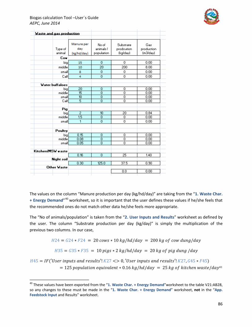
Biogas calculation Tool –User´s Guide AEPC, June 2014
86
The values on the column “Manure production per day (kg/hd/day)” are taking from the “1. Waste Char. + Energy Demand”40
40 These values have been exported from the “1. Waste Char. + Energy Demand”worksheet to the table V21:AB28, so any changes to these must be made in the “1. Waste Char. + Energy Demand” worksheet, not in the “App. Feedstock Input and Results” worksheet.
worksheet, so it is important that the user defines these values if he/she feels that the recommended ones do not match other data he/she feels more appropriate.
The “No of animals/population” is taken from the “2. User Inputs and Results” worksheet as defined by the user. The column “Substrate production per day (kg/day)” is simply the multiplication of the previous two columns. In our case,
𝐻𝐻24 = 𝐺𝐺24 ∗ 𝐹𝐹24 = 20 𝑖𝑖𝐵𝐵𝑤𝑤𝐵𝐵 ∗ 10 𝑘𝑘𝐵𝐵/ℎ𝑦𝑦/𝑦𝑦𝐵𝐵𝑦𝑦 = 200 𝑘𝑘𝐵𝐵 𝐵𝐵𝑜𝑜 𝑖𝑖𝐵𝐵𝑤𝑤 𝑦𝑦𝑛𝑛𝑛𝑛𝐵𝐵/𝑦𝑦𝐵𝐵𝑦𝑦
𝐻𝐻35 = 𝐺𝐺35 ∗ 𝐹𝐹35 = 10 𝑝𝑝𝐵𝐵𝐵𝐵𝐵𝐵 ∗ 2 𝑘𝑘𝐵𝐵/ℎ𝑦𝑦/𝑦𝑦𝐵𝐵𝑦𝑦 = 20 𝑘𝑘𝐵𝐵 𝐵𝐵𝑜𝑜 𝑝𝑝𝐵𝐵𝐵𝐵 𝑦𝑦𝑛𝑛𝑛𝑛𝐵𝐵 /𝑦𝑦𝐵𝐵𝑦𝑦
𝐻𝐻45 = 𝐼𝐼𝐹𝐹(′𝑈𝑈𝐵𝐵𝑦𝑦𝑛𝑛 𝐵𝐵𝑛𝑛𝑝𝑝𝑛𝑛𝑤𝑤𝐵𝐵 𝐵𝐵𝑛𝑛𝑦𝑦 𝑛𝑛𝑦𝑦𝐵𝐵𝑛𝑛𝑦𝑦𝑤𝑤𝐵𝐵′! 𝐾𝐾27 <> 0, ′𝑈𝑈𝐵𝐵𝑦𝑦𝑛𝑛 𝐵𝐵𝑛𝑛𝑝𝑝𝑛𝑛𝑤𝑤𝐵𝐵 𝐵𝐵𝑛𝑛𝑦𝑦 𝑛𝑛𝑦𝑦𝐵𝐵𝑛𝑛𝑦𝑦𝑤𝑤𝐵𝐵′! 𝐾𝐾27, 𝐺𝐺45 ∗ 𝐹𝐹45)= 125 𝑝𝑝𝐵𝐵𝑝𝑝𝑛𝑛𝑦𝑦𝐵𝐵𝑤𝑤𝐵𝐵𝐵𝐵𝑛𝑛 𝑦𝑦𝑒𝑒𝑛𝑛𝐵𝐵𝑅𝑅𝐵𝐵𝑦𝑦𝑦𝑦𝑛𝑛𝑤𝑤 ∗ 0.16 𝑘𝑘𝐵𝐵/ℎ𝑦𝑦/𝑦𝑦𝐵𝐵𝑦𝑦 = 25 𝑘𝑘𝐵𝐵 𝐵𝐵𝑜𝑜 𝑘𝑘𝐵𝐵𝑤𝑤𝑖𝑖ℎ𝑦𝑦𝑛𝑛 𝑤𝑤𝐵𝐵𝐵𝐵𝑤𝑤𝑦𝑦/𝑦𝑦𝐵𝐵𝑦𝑦41
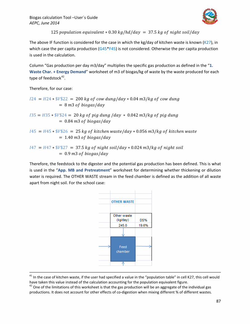
Biogas calculation Tool –User´s Guide AEPC, June 2014
87
125 𝑝𝑝𝐵𝐵𝑝𝑝𝑛𝑛𝑦𝑦𝐵𝐵𝑤𝑤𝐵𝐵𝐵𝐵𝑛𝑛 𝑦𝑦𝑒𝑒𝑛𝑛𝐵𝐵𝑅𝑅𝐵𝐵𝑦𝑦𝑦𝑦𝑛𝑛𝑤𝑤 ∗ 0.30 𝑘𝑘𝐵𝐵/ℎ𝑦𝑦/𝑦𝑦𝐵𝐵𝑦𝑦 = 37.5 𝑘𝑘𝐵𝐵 𝐵𝐵𝑜𝑜 𝑛𝑛𝐵𝐵𝐵𝐵ℎ𝑤𝑤 𝐵𝐵𝐵𝐵𝐵𝐵𝑦𝑦/𝑦𝑦𝐵𝐵𝑦𝑦
The above IF function is considered for the case in which the kg/day of kitchen waste is known (K27), in which case the per capita production (G45*F45) is not considered. Otherwise the per capita production is used in the calculation.
Column “Gas production per day m3/day” multiplies the specific gas production as defined in the “1. Waste Char. + Energy Demand” worksheet of m3 of biogas/kg of waste by the waste produced for each type of feedstock42
.
Therefore, for our case:
𝐼𝐼24 = 𝐻𝐻24 ∗ $𝑉𝑉$22 = 200 𝑘𝑘𝐵𝐵 𝐵𝐵𝑜𝑜 𝑖𝑖𝐵𝐵𝑤𝑤 𝑦𝑦𝑛𝑛𝑛𝑛𝐵𝐵/𝑦𝑦𝐵𝐵𝑦𝑦 ∗ 0.04 𝑚𝑚3/𝑘𝑘𝐵𝐵 𝐵𝐵𝑜𝑜 𝑖𝑖𝐵𝐵𝑤𝑤 𝑦𝑦𝑛𝑛𝑛𝑛𝐵𝐵 = 8 𝑚𝑚3 𝐵𝐵𝑜𝑜 𝑛𝑛𝐵𝐵𝐵𝐵𝐵𝐵𝐵𝐵𝐵𝐵/𝑦𝑦𝐵𝐵𝑦𝑦
𝐼𝐼35 = 𝐻𝐻35 ∗ $𝑉𝑉$24 = 20 𝑘𝑘𝐵𝐵 𝐵𝐵𝑜𝑜 𝑝𝑝𝐵𝐵𝐵𝐵 𝑦𝑦𝑛𝑛𝑛𝑛𝐵𝐵 /𝑦𝑦𝐵𝐵𝑦𝑦 ∗ 0.042 𝑚𝑚3/𝑘𝑘𝐵𝐵 𝐵𝐵𝑜𝑜 𝑝𝑝𝐵𝐵𝐵𝐵 𝑦𝑦𝑛𝑛𝑛𝑛𝐵𝐵 = 0.84 𝑚𝑚3 𝐵𝐵𝑜𝑜 𝑛𝑛𝐵𝐵𝐵𝐵𝐵𝐵𝐵𝐵𝐵𝐵/𝑦𝑦𝐵𝐵𝑦𝑦
𝐼𝐼45 = 𝐻𝐻45 ∗ $𝑉𝑉$26 = 25 𝑘𝑘𝐵𝐵 𝐵𝐵𝑜𝑜 𝑘𝑘𝐵𝐵𝑤𝑤𝑖𝑖ℎ𝑦𝑦𝑛𝑛 𝑤𝑤𝐵𝐵𝐵𝐵𝑤𝑤𝑦𝑦/𝑦𝑦𝐵𝐵𝑦𝑦 ∗ 0.056 𝑚𝑚3/𝑘𝑘𝐵𝐵 𝐵𝐵𝑜𝑜 𝑘𝑘𝐵𝐵𝑤𝑤𝑖𝑖ℎ𝑦𝑦𝑛𝑛 𝑤𝑤𝐵𝐵𝐵𝐵𝑤𝑤𝑦𝑦 = 1.40 𝑚𝑚3 𝐵𝐵𝑜𝑜 𝑛𝑛𝐵𝐵𝐵𝐵𝐵𝐵𝐵𝐵𝐵𝐵/𝑦𝑦𝐵𝐵𝑦𝑦
𝐼𝐼47 = 𝐻𝐻47 ∗ $𝑉𝑉$27 = 37.5 𝑘𝑘𝐵𝐵 𝐵𝐵𝑜𝑜 𝑛𝑛𝐵𝐵𝐵𝐵ℎ𝑤𝑤 𝐵𝐵𝐵𝐵𝐵𝐵𝑦𝑦/𝑦𝑦𝐵𝐵𝑦𝑦 ∗ 0.024 𝑚𝑚3/𝑘𝑘𝐵𝐵 𝐵𝐵𝑜𝑜 𝑛𝑛𝐵𝐵𝐵𝐵ℎ𝑤𝑤 𝐵𝐵𝐵𝐵𝐵𝐵𝑦𝑦 = 0.9 𝑚𝑚3 𝐵𝐵𝑜𝑜 𝑛𝑛𝐵𝐵𝐵𝐵𝐵𝐵𝐵𝐵𝐵𝐵/𝑦𝑦𝐵𝐵𝑦𝑦
Therefore, the feedstock to the digester and the potential gas production has been defined. This is what is used in the “App. MB and Pretreatment” worksheet for determining whether thickening or dilution water is required. The OTHER WASTE stream in the feed chamber is defined as the addition of all waste apart from night soil. For the school case:
41 In the case of kitchen waste, if the user had specified a value in the “population table” in cell K27, this cell would have taken this value instead of the calculation accounting for the population equivalent figure. 42 One of the limitations of this worksheet is that the gas production will be an aggregate of the individual gas productions. It does not account for other effects of co-digestion when mixing different % of different wastes.
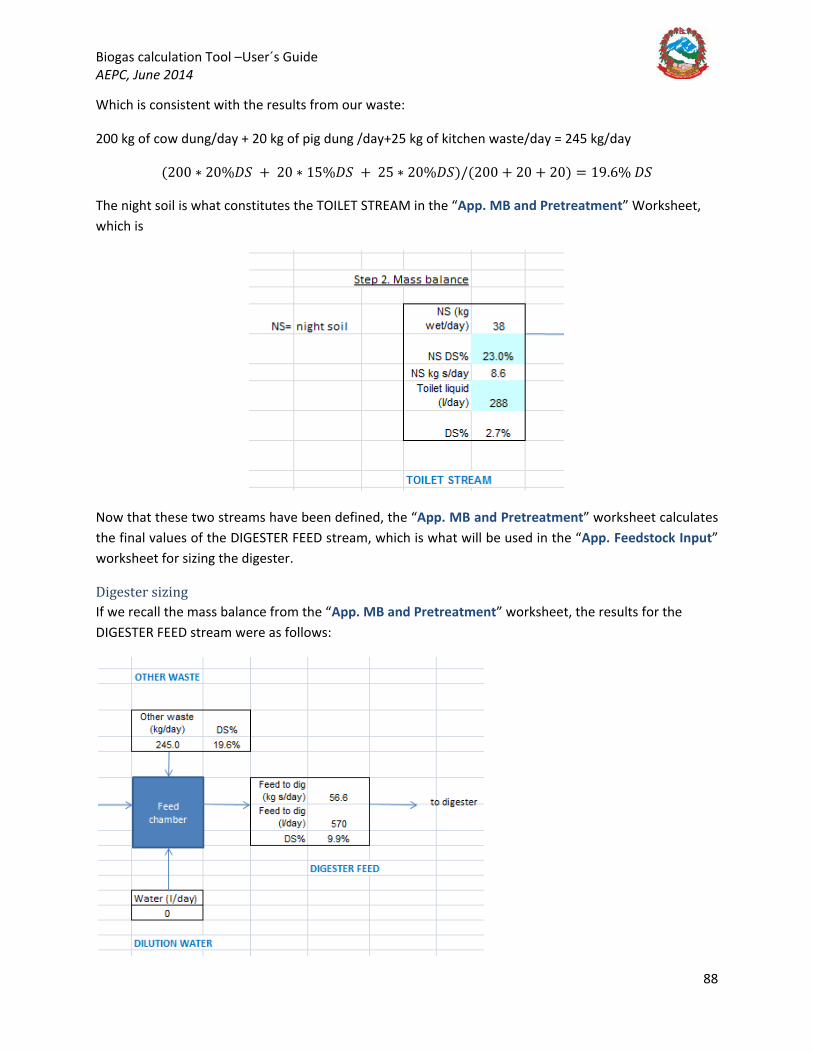
Biogas calculation Tool –User´s Guide AEPC, June 2014
88
Which is consistent with the results from our waste:
200 kg of cow dung/day + 20 kg of pig dung /day+25 kg of kitchen waste/day = 245 kg/day
(200 ∗ 20%𝐴𝐴𝑉𝑉 + 20 ∗ 15%𝐴𝐴𝑉𝑉 + 25 ∗ 20%𝐴𝐴𝑉𝑉)/(200 + 20 + 20) = 19.6% 𝐴𝐴𝑉𝑉
The night soil is what constitutes the TOILET STREAM in the “App. MB and Pretreatment” Worksheet, which is
Now that these two streams have been defined, the “App. MB and Pretreatment” worksheet calculates the final values of the DIGESTER FEED stream, which is what will be used in the “App. Feedstock Input” worksheet for sizing the digester.
Digester sizing If we recall the mass balance from the “App. MB and Pretreatment” worksheet, the results for the DIGESTER FEED stream were as follows:

Biogas calculation Tool –User´s Guide AEPC, June 2014
89
The DIGESTER FEED is what will be used to size the digester based on the retention time that is determined by the selection of location or technology in “2. User Inputs and Results”. As a reminder:
And these are the parameters that the user can modify in the “2. User Inputs and Results” worksheet.
Therefore, for a retention time of 55 days and a feed of 570 l/day (or 0.57 m3/day), the following formula applies:
𝑇𝑇𝐵𝐵𝑤𝑤𝐵𝐵𝑦𝑦 𝐴𝐴𝐵𝐵𝐵𝐵𝑦𝑦𝐵𝐵𝑤𝑤𝑦𝑦𝑛𝑛 𝑉𝑉𝐵𝐵𝑦𝑦𝑛𝑛𝑚𝑚𝑦𝑦 = 𝐺𝐺58 = 𝐻𝐻𝑂𝑂𝑇𝑇 ∗ 𝑄𝑄 =′ 𝑈𝑈𝐵𝐵𝑦𝑦𝑛𝑛 𝐵𝐵𝑛𝑛𝑝𝑝𝑛𝑛𝑤𝑤𝐵𝐵 𝐵𝐵𝑛𝑛𝑦𝑦 𝑛𝑛𝑦𝑦𝐵𝐵𝑛𝑛𝑦𝑦𝑤𝑤𝐵𝐵′ ! 𝐹𝐹42 ∗ 𝐷𝐷58
= 55 𝑦𝑦𝐵𝐵𝑦𝑦𝐵𝐵 ∗ 0.57𝑚𝑚3𝑦𝑦𝐵𝐵𝑦𝑦
= 31 𝑚𝑚3
Where
𝐻𝐻𝑂𝑂𝑇𝑇 = 𝐻𝐻𝑦𝑦𝑦𝑦𝑛𝑛𝐵𝐵𝑛𝑛𝑦𝑦𝐵𝐵𝑖𝑖 𝑂𝑂𝑦𝑦𝑤𝑤𝑦𝑦𝑛𝑛𝑤𝑤𝐵𝐵𝐵𝐵𝑛𝑛 𝑇𝑇𝐵𝐵𝑚𝑚𝑦𝑦 (𝐻𝐻𝑂𝑂𝑇𝑇)
𝑄𝑄 = 𝐴𝐴𝐵𝐵𝐵𝐵𝑦𝑦𝐵𝐵𝑤𝑤𝑦𝑦𝑛𝑛 𝑜𝑜𝑦𝑦𝑦𝑦𝑦𝑦 𝑜𝑜𝑦𝑦𝐵𝐵𝑤𝑤 (𝑚𝑚3/𝑦𝑦𝐵𝐵𝑦𝑦), 𝑤𝑤𝐵𝐵𝑘𝑘𝑦𝑦𝑛𝑛 𝑜𝑜𝑛𝑛𝐵𝐵𝑚𝑚 𝑖𝑖𝑦𝑦𝑦𝑦𝑦𝑦 𝐷𝐷58 = ′𝑀𝑀𝐵𝐵 𝐵𝐵𝑛𝑛𝑦𝑦 𝑝𝑝𝑛𝑛𝑦𝑦𝑤𝑤𝑛𝑛𝑦𝑦𝐵𝐵𝑤𝑤𝑚𝑚𝑦𝑦𝑛𝑛𝑤𝑤′! 𝑂𝑂25/1000
In order to calculate the Gas Storage Volume, the worksheet assumes a % increase of total biogas plant volume including the gas storage volume for the modified GGC 2047 model as per the designs available. This is defined in the “2. User Inputs and Results” Step 2. The spreadsheet assumes 50% increase from the Total Digester Volume to the Biogas Plant Volume, based on the average increase for the modified GGC 2047 model. This % increase could be modified by the user if a different type of plant is selected43
43 This will be developed to gas storage volume based on the number of hours storage time required. However, currently the subsidy provision depends on the whole plant volume as a unit. As of when the subsidy policy is changed more flexibility will be allowed for the designer, and the spreadsheet will be modified accordingly.
. However, the Gas Storage Volume also accounts for “Other” types of storage based on a given retention time set by the user in the “User´s Inputs and Results” worksheet, K40, which is imported to H58 in the “App. Feedstock Input” worksheet.
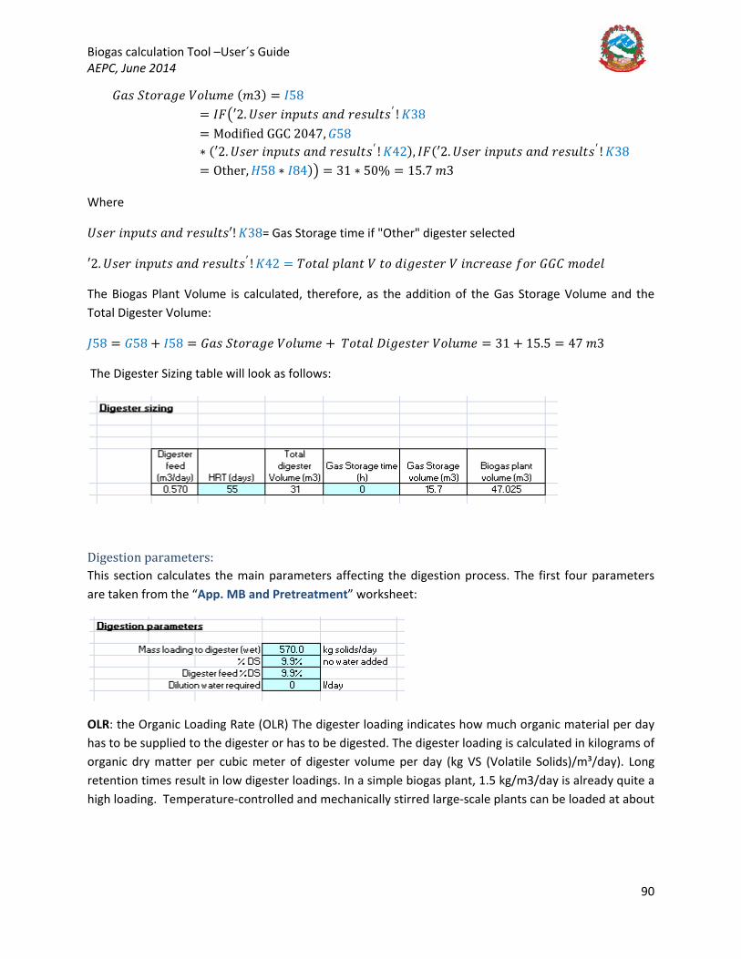
Biogas calculation Tool –User´s Guide AEPC, June 2014
90
𝐺𝐺𝐵𝐵𝐵𝐵 𝑉𝑉𝑤𝑤𝐵𝐵𝑛𝑛𝐵𝐵𝐵𝐵𝑦𝑦 𝑉𝑉𝐵𝐵𝑦𝑦𝑛𝑛𝑚𝑚𝑦𝑦 (𝑚𝑚3) = 𝐼𝐼58= 𝐼𝐼𝐹𝐹�′2. 𝑈𝑈𝐵𝐵𝑦𝑦𝑛𝑛 𝐵𝐵𝑛𝑛𝑝𝑝𝑛𝑛𝑤𝑤𝐵𝐵 𝐵𝐵𝑛𝑛𝑦𝑦 𝑛𝑛𝑦𝑦𝐵𝐵𝑛𝑛𝑦𝑦𝑤𝑤𝐵𝐵′ ! 𝐾𝐾38= Modified GGC 2047, 𝐺𝐺58∗ (′2. 𝑈𝑈𝐵𝐵𝑦𝑦𝑛𝑛 𝐵𝐵𝑛𝑛𝑝𝑝𝑛𝑛𝑤𝑤𝐵𝐵 𝐵𝐵𝑛𝑛𝑦𝑦 𝑛𝑛𝑦𝑦𝐵𝐵𝑛𝑛𝑦𝑦𝑤𝑤𝐵𝐵′ ! 𝐾𝐾42), 𝐼𝐼𝐹𝐹(′2. 𝑈𝑈𝐵𝐵𝑦𝑦𝑛𝑛 𝐵𝐵𝑛𝑛𝑝𝑝𝑛𝑛𝑤𝑤𝐵𝐵 𝐵𝐵𝑛𝑛𝑦𝑦 𝑛𝑛𝑦𝑦𝐵𝐵𝑛𝑛𝑦𝑦𝑤𝑤𝐵𝐵′ ! 𝐾𝐾38= Other, 𝐻𝐻58 ∗ 𝐼𝐼84)� = 31 ∗ 50% = 15.7 𝑚𝑚3
Where
𝑈𝑈𝐵𝐵𝑦𝑦𝑛𝑛 𝐵𝐵𝑛𝑛𝑝𝑝𝑛𝑛𝑤𝑤𝐵𝐵 𝐵𝐵𝑛𝑛𝑦𝑦 𝑛𝑛𝑦𝑦𝐵𝐵𝑛𝑛𝑦𝑦𝑤𝑤𝐵𝐵′! 𝐾𝐾38= Gas Storage time if "Other" digester selected
′2. 𝑈𝑈𝐵𝐵𝑦𝑦𝑛𝑛 𝐵𝐵𝑛𝑛𝑝𝑝𝑛𝑛𝑤𝑤𝐵𝐵 𝐵𝐵𝑛𝑛𝑦𝑦 𝑛𝑛𝑦𝑦𝐵𝐵𝑛𝑛𝑦𝑦𝑤𝑤𝐵𝐵′ ! 𝐾𝐾42 = 𝑇𝑇𝐵𝐵𝑤𝑤𝐵𝐵𝑦𝑦 𝑝𝑝𝑦𝑦𝐵𝐵𝑛𝑛𝑤𝑤 𝑉𝑉 𝑤𝑤𝐵𝐵 𝑦𝑦𝐵𝐵𝐵𝐵𝑦𝑦𝐵𝐵𝑤𝑤𝑦𝑦𝑛𝑛 𝑉𝑉 𝐵𝐵𝑛𝑛𝑖𝑖𝑛𝑛𝑦𝑦𝐵𝐵𝐵𝐵𝑦𝑦 𝑜𝑜𝐵𝐵𝑛𝑛 𝐺𝐺𝐺𝐺𝐶𝐶 𝑚𝑚𝐵𝐵𝑦𝑦𝑦𝑦𝑦𝑦
The Biogas Plant Volume is calculated, therefore, as the addition of the Gas Storage Volume and the Total Digester Volume:
𝑀𝑀58 = 𝐺𝐺58 + 𝐼𝐼58 = 𝐺𝐺𝐵𝐵𝐵𝐵 𝑉𝑉𝑤𝑤𝐵𝐵𝑛𝑛𝐵𝐵𝐵𝐵𝑦𝑦 𝑉𝑉𝐵𝐵𝑦𝑦𝑛𝑛𝑚𝑚𝑦𝑦 + 𝑇𝑇𝐵𝐵𝑤𝑤𝐵𝐵𝑦𝑦 𝐴𝐴𝐵𝐵𝐵𝐵𝑦𝑦𝐵𝐵𝑤𝑤𝑦𝑦𝑛𝑛 𝑉𝑉𝐵𝐵𝑦𝑦𝑛𝑛𝑚𝑚𝑦𝑦 = 31 + 15.5 = 47 𝑚𝑚3
The Digester Sizing table will look as follows:
Digestion parameters: This section calculates the main parameters affecting the digestion process. The first four parameters are taken from the “App. MB and Pretreatment” worksheet:
OLR: the Organic Loading Rate (OLR) The digester loading indicates how much organic material per day has to be supplied to the digester or has to be digested. The digester loading is calculated in kilograms of organic dry matter per cubic meter of digester volume per day (kg VS (Volatile Solids)/m³/day). Long retention times result in low digester loadings. In a simple biogas plant, 1.5 kg/m3/day is already quite a high loading. Temperature-controlled and mechanically stirred large-scale plants can be loaded at about

Biogas calculation Tool –User´s Guide AEPC, June 2014
91
5 kg/m3/day. If the digester loading is too high, the pH falls. The plant then remains in the acid phase because there is more feed material than methane bacteria44
𝐼𝐼68 = 𝐼𝐼𝐹𝐹(𝐴𝐴𝑁𝑁𝐴𝐴(𝐺𝐺68 <= 𝑂𝑂64, ′2. 𝑈𝑈𝐵𝐵𝑦𝑦𝑛𝑛 𝐵𝐵𝑛𝑛𝑝𝑝𝑛𝑛𝑤𝑤𝐵𝐵 𝐵𝐵𝑛𝑛𝑦𝑦 𝑛𝑛𝑦𝑦𝐵𝐵𝑛𝑛𝑦𝑦𝑤𝑤𝐵𝐵′! 𝐾𝐾38= "𝑚𝑚𝐵𝐵𝑦𝑦𝐵𝐵𝑜𝑜𝐵𝐵𝑦𝑦𝑦𝑦 𝐺𝐺𝐺𝐺𝐶𝐶 2047"), "𝑶𝑶𝑶𝑶𝑹𝑹 𝑶𝑶𝑶𝑶", 𝐼𝐼𝐹𝐹(𝐴𝐴𝑁𝑁𝐴𝐴(𝐺𝐺68 > 𝑂𝑂64, ′2. 𝑈𝑈𝐵𝐵𝑦𝑦𝑛𝑛 𝐵𝐵𝑛𝑛𝑝𝑝𝑛𝑛𝑤𝑤𝐵𝐵 𝐵𝐵𝑛𝑛𝑦𝑦 𝑛𝑛𝑦𝑦𝐵𝐵𝑛𝑛𝑦𝑦𝑤𝑤𝐵𝐵′! 𝐾𝐾38= "𝑚𝑚𝐵𝐵𝑦𝑦𝐵𝐵𝑜𝑜𝐵𝐵𝑦𝑦𝑦𝑦 𝐺𝐺𝐺𝐺𝐶𝐶 2047"), "𝑶𝑶𝑶𝑶𝑹𝑹 𝑻𝑻𝑶𝑶𝑶𝑶 𝑯𝑯𝑰𝑰𝑯𝑯𝑯𝑯", 𝐼𝐼𝐹𝐹(𝐴𝐴𝑁𝑁𝐴𝐴(′2. 𝑈𝑈𝐵𝐵𝑦𝑦𝑛𝑛 𝐵𝐵𝑛𝑛𝑝𝑝𝑛𝑛𝑤𝑤𝐵𝐵 𝐵𝐵𝑛𝑛𝑦𝑦 𝑛𝑛𝑦𝑦𝐵𝐵𝑛𝑛𝑦𝑦𝑤𝑤𝐵𝐵′! 𝐾𝐾38= "𝑂𝑂𝑤𝑤ℎ𝑦𝑦𝑛𝑛", 𝐺𝐺68 <= 𝑂𝑂65), "𝑶𝑶𝑶𝑶", 𝐼𝐼𝐹𝐹(𝐴𝐴𝑁𝑁𝐴𝐴(𝐺𝐺68 > 𝑂𝑂65, ′2. 𝑈𝑈𝐵𝐵𝑦𝑦𝑛𝑛 𝐵𝐵𝑛𝑛𝑝𝑝𝑛𝑛𝑤𝑤𝐵𝐵 𝐵𝐵𝑛𝑛𝑦𝑦 𝑛𝑛𝑦𝑦𝐵𝐵𝑛𝑛𝑦𝑦𝑤𝑤𝐵𝐵′! 𝐾𝐾38= "𝑂𝑂𝑤𝑤ℎ𝑦𝑦𝑛𝑛"), "𝑶𝑶𝑶𝑶𝑹𝑹 𝑻𝑻𝑶𝑶𝑶𝑶 𝑯𝑯𝑰𝑰𝑯𝑯𝑯𝑯", ""))))
.
Therefore, the OLR is calculated in the spreadsheet as the proportional contribution of Volatile Solids (VS) from each substrate. The volatile solids are a % of the Total Solids, which are, as the VS%, taken from the Waste Characterisation table that is in V21:AB28, imported from the “1. Waste Char. + Energy Demand” worksheet, and these are accounted for as follows:
𝑂𝑂𝐿𝐿𝑂𝑂 = 𝐺𝐺68
=𝑉𝑉𝑈𝑈𝑀𝑀(𝐻𝐻23: 𝐻𝐻26) ∗ 𝑌𝑌22 ∗ 𝑍𝑍22 + 𝑉𝑉𝑈𝑈𝑀𝑀(𝐻𝐻29: 𝐻𝐻32) ∗ 𝑌𝑌23 ∗ 𝑍𝑍23 + 𝑉𝑉𝑈𝑈𝑀𝑀(𝐻𝐻35: 𝐻𝐻37) ∗ 𝑌𝑌24 ∗ 𝑍𝑍24 + 𝑉𝑉𝑈𝑈𝑀𝑀(𝐻𝐻40: 𝐻𝐻42) ∗ 𝑌𝑌25 ∗ 𝑍𝑍25 + 𝐻𝐻45 ∗ 𝑌𝑌26 ∗ 𝑍𝑍26 + 𝐻𝐻47 ∗ 𝑌𝑌27 ∗ 𝑍𝑍27 + 𝐻𝐻49 ∗ 𝑌𝑌28 ∗ 𝑍𝑍28
𝐺𝐺58
=200 𝑘𝑘𝐵𝐵 𝑖𝑖𝐵𝐵𝑤𝑤 𝑦𝑦𝑛𝑛𝑛𝑛𝐵𝐵 ∗ 20% ∗ 80% + 20 𝑘𝑘𝐵𝐵 𝑝𝑝𝐵𝐵𝐵𝐵 𝑚𝑚𝐵𝐵𝑛𝑛𝑛𝑛𝑛𝑛𝑦𝑦 ∗ 15% ∗ 75% + 25 𝑘𝑘𝐵𝐵 𝐵𝐵𝑜𝑜 𝑘𝑘𝐵𝐵𝑤𝑤𝑖𝑖ℎ𝑦𝑦𝑛𝑛 𝑤𝑤𝐵𝐵𝐵𝐵𝑤𝑤𝑦𝑦 ∗ 20% ∗ 80% + 37.5 𝑘𝑘𝐵𝐵 𝐵𝐵𝑜𝑜 𝑤𝑤𝐵𝐵𝐵𝐵𝑦𝑦𝑦𝑦𝑤𝑤 𝑤𝑤𝐵𝐵𝐵𝐵𝑤𝑤𝑦𝑦 ∗ 23% ∗ 8′ %
31 𝑚𝑚3 𝑤𝑤𝐵𝐵𝑤𝑤𝐵𝐵𝑦𝑦 𝑦𝑦𝐵𝐵𝐵𝐵𝑦𝑦𝐵𝐵𝑤𝑤𝑦𝑦𝑛𝑛 𝑅𝑅𝐵𝐵𝑦𝑦𝑛𝑛𝑚𝑚𝑦𝑦
= 1.44 𝑘𝑘𝐵𝐵 𝐵𝐵𝑜𝑜𝑉𝑉𝑉𝑉
𝑚𝑚3 ∗ 𝑦𝑦𝐵𝐵𝑦𝑦
Cell I68 will compare the value obtained to the recommended values depending on the type of digester, which the user can modify in cells R64 and R65.
C/N ratio: Microorganisms need both nitrogen and carbon for assimilation into their cell structures. Various experiments have shown that the metabolic activity of methanogenic bacteria can be optimized at a C/N ratio of approximately 8-20, whereby the optimum point varies from case to case, depending on the nature of the substrate45
. The spreadsheet calculates this as a proportional contribution from each substrate as for the OLR, as follows: 𝐶𝐶𝑁𝑁
𝑛𝑛𝐵𝐵𝑤𝑤𝐵𝐵𝐵𝐵 = 𝐺𝐺69
=𝑉𝑉𝑈𝑈𝑀𝑀(𝐻𝐻23: 𝐻𝐻26) ∗ 𝐷𝐷22 + 𝑉𝑉𝑈𝑈𝑀𝑀(𝐻𝐻29: 𝐻𝐻32) ∗ 𝐷𝐷23 + 𝑉𝑉𝑈𝑈𝑀𝑀(𝐻𝐻35: 𝐻𝐻37) ∗ 𝐷𝐷24 + 𝑉𝑉𝑈𝑈𝑀𝑀(𝐻𝐻40: 𝐻𝐻42) ∗ 𝐷𝐷25 + 𝐻𝐻45 ∗ 𝐷𝐷26 + 𝐻𝐻47 ∗ 𝐷𝐷27 + 𝐻𝐻49 ∗ 𝐷𝐷28
𝑉𝑉𝑈𝑈𝑀𝑀(𝐻𝐻23: 𝐻𝐻49)= 18.5 Cell H69 compares these values with the user modifiable values in cell R68 and R69, to see whether the C/N ratio is adequate:
44 Biogas Plants, Ludwig Sasse, GTZ, 1988. 45 Biogas Digest, Volume I, Biogas Basics, GTZ, 1999.

Biogas calculation Tool –User´s Guide AEPC, June 2014
92
𝐻𝐻69 = 𝐼𝐼𝐹𝐹(𝐺𝐺69 > 𝑂𝑂69, "𝑪𝑪𝑪𝑪 𝑻𝑻𝑶𝑶𝑶𝑶 𝑯𝑯𝑰𝑰𝑯𝑯𝑯𝑯", 𝐼𝐼𝐹𝐹(𝐺𝐺69 < 𝑂𝑂68, "𝑪𝑪𝑪𝑪 𝑻𝑻𝑶𝑶𝑶𝑶 𝑶𝑶𝑶𝑶𝑳𝑳", "𝑶𝑶𝑶𝑶"))
The next thing the worksheet calculates is the potential compost production. For this, the assumption is that 60% (modifiable by user) of the volatile solids fed to the digester are destroyed to produce methane in the digestion process. Cell J69 calculates the VS loading to the digester (similarly to the OLR), and K69 calculates the VS destroyed based on the assumption above:
𝑀𝑀69 = 𝑉𝑉𝑈𝑈𝑀𝑀(𝐻𝐻23: 𝐻𝐻26) ∗ 𝑌𝑌22 ∗ 𝑍𝑍22 + 𝑉𝑉𝑈𝑈𝑀𝑀(𝐻𝐻29: 𝐻𝐻32) ∗ 𝑌𝑌23 ∗ 𝑍𝑍23 + 𝑉𝑉𝑈𝑈𝑀𝑀(𝐻𝐻35: 𝐻𝐻37) ∗ 𝑌𝑌24 ∗ 𝑍𝑍24 + 𝑉𝑉𝑈𝑈𝑀𝑀(𝐻𝐻40: 𝐻𝐻42)∗ 𝑌𝑌25 ∗ 𝑍𝑍25 + 𝐻𝐻45 ∗ 𝑌𝑌26 ∗ 𝑍𝑍26 + 𝐻𝐻47 ∗ 𝑌𝑌27 ∗ 𝑍𝑍27 + 𝐻𝐻49 ∗ 𝑌𝑌28 ∗ 𝑍𝑍28= 200 𝑘𝑘𝐵𝐵 𝑖𝑖𝐵𝐵𝑤𝑤 𝑦𝑦𝑛𝑛𝑛𝑛𝐵𝐵 ∗ 20% ∗ 80% + 20 𝑘𝑘𝐵𝐵 𝑝𝑝𝐵𝐵𝐵𝐵 𝑚𝑚𝐵𝐵𝑛𝑛𝑛𝑛𝑛𝑛𝑦𝑦 ∗ 15% ∗ 75% + 25 𝑘𝑘𝐵𝐵 𝐵𝐵𝑜𝑜 𝑘𝑘𝐵𝐵𝑤𝑤𝑖𝑖ℎ𝑦𝑦𝑛𝑛 𝑤𝑤𝐵𝐵𝐵𝐵𝑤𝑤𝑦𝑦 ∗ 20%∗ 80% + 37.5 𝑘𝑘𝐵𝐵 𝐵𝐵𝑜𝑜 𝑤𝑤𝐵𝐵𝐵𝐵𝑦𝑦𝑦𝑦𝑤𝑤 𝑤𝑤𝐵𝐵𝐵𝐵𝑤𝑤𝑦𝑦 ∗ 23% ∗ 80% = 45.2 𝑘𝑘𝐵𝐵 𝐵𝐵𝑜𝑜 𝑉𝑉𝑉𝑉/𝑦𝑦𝐵𝐵𝑦𝑦
𝐾𝐾69 = 𝑀𝑀69 ∗ 𝐺𝐺69 = 𝐴𝐴𝐵𝐵𝐵𝐵𝑦𝑦𝐵𝐵𝑤𝑤𝑦𝑦𝑛𝑛 𝑉𝑉𝑉𝑉 𝑜𝑜𝑦𝑦𝑦𝑦𝑦𝑦 𝑘𝑘𝐵𝐵/𝑦𝑦𝐵𝐵𝑦𝑦 ∗ 60% 𝑉𝑉𝑉𝑉 𝑦𝑦𝑦𝑦𝐵𝐵𝑤𝑤𝑛𝑛𝑛𝑛𝑖𝑖𝑤𝑤𝐵𝐵𝐵𝐵𝑛𝑛 = 27.1 𝑘𝑘𝐵𝐵 𝐵𝐵𝑜𝑜 𝑉𝑉𝑉𝑉/𝑦𝑦𝐵𝐵𝑦𝑦
Now, performing a mass balance to the solids entering the digester:
𝐴𝐴𝐵𝐵𝐵𝐵𝑦𝑦𝐵𝐵𝑤𝑤𝑦𝑦𝑛𝑛 𝑉𝑉𝑦𝑦𝑛𝑛𝑛𝑛𝑛𝑛𝑦𝑦 𝑀𝑀𝐵𝐵𝐵𝐵𝐵𝐵 𝐴𝐴𝑛𝑛𝑦𝑦 = 𝐹𝐹𝑦𝑦𝑦𝑦𝑦𝑦 𝑤𝑤𝐵𝐵 𝑦𝑦𝐵𝐵𝐵𝐵𝑦𝑦𝐵𝐵𝑤𝑤𝑦𝑦𝑛𝑛 (𝑘𝑘𝐵𝐵 𝐵𝐵𝑜𝑜 𝐵𝐵𝐵𝐵𝑦𝑦𝐵𝐵𝑦𝑦𝐵𝐵/𝑦𝑦𝐵𝐵𝑦𝑦) – 𝑉𝑉𝑉𝑉 𝑦𝑦𝑦𝑦𝐵𝐵𝑤𝑤𝑛𝑛𝐵𝐵𝑦𝑦𝑦𝑦𝑦𝑦 = ′𝑀𝑀𝐵𝐵 𝐵𝐵𝑛𝑛𝑦𝑦 𝑝𝑝𝑛𝑛𝑦𝑦𝑤𝑤𝑛𝑛𝑦𝑦𝐵𝐵𝑤𝑤𝑚𝑚𝑦𝑦𝑛𝑛𝑤𝑤′! $𝑂𝑂$24 − 𝐾𝐾69 = 56.6 – 27.1 = 29.5 𝑘𝑘𝐵𝐵 𝐵𝐵𝑜𝑜 𝐵𝐵𝐵𝐵𝑦𝑦𝐵𝐵𝑦𝑦𝐵𝐵/𝑦𝑦𝐵𝐵𝑦𝑦
The DS% of the Digester Slurry will be:
𝐴𝐴𝐵𝐵𝐵𝐵𝑦𝑦𝐵𝐵𝑤𝑤𝑦𝑦𝑛𝑛 𝑉𝑉𝑦𝑦𝑛𝑛𝑛𝑛𝑛𝑛𝑦𝑦 𝐴𝐴𝑉𝑉% = 𝐺𝐺73 = 𝐺𝐺71/𝐺𝐺72= 𝐴𝐴𝐵𝐵𝐵𝐵𝑦𝑦𝐵𝐵𝑤𝑤𝑦𝑦𝑛𝑛 𝐵𝐵𝑦𝑦𝑛𝑛𝑛𝑛𝑛𝑛𝑦𝑦 𝑚𝑚𝐵𝐵𝐵𝐵𝐵𝐵 𝑦𝑦𝑛𝑛𝑦𝑦/𝐴𝐴𝐵𝐵𝐵𝐵𝑦𝑦𝐵𝐵𝑤𝑤𝑦𝑦𝑛𝑛 𝑉𝑉𝑦𝑦𝑛𝑛𝑛𝑛𝑛𝑛𝑦𝑦 𝑚𝑚𝐵𝐵𝐵𝐵𝐵𝐵 𝑤𝑤𝑦𝑦𝑤𝑤 = 29.5/570 = 5.2%
The sludge will be dried in the compost pits. The user shall set the DS% of compost in cell P56 of the “2. User Inputs and Results” worksheet (suggested 50%), this is imported in cell K71. The mass balance to calculate the amount of compost to be produced is:
𝐶𝐶𝐵𝐵𝑚𝑚𝑝𝑝𝐵𝐵𝐵𝐵𝑤𝑤 𝑝𝑝𝑛𝑛𝐵𝐵𝑦𝑦𝑛𝑛𝑖𝑖𝑤𝑤𝐵𝐵𝐵𝐵𝑛𝑛 = 𝐾𝐾72 = 𝐺𝐺72∗𝐺𝐺73𝐾𝐾71
= 𝐴𝐴𝐵𝐵𝐵𝐵𝑦𝑦𝐵𝐵𝑤𝑤𝑦𝑦𝑛𝑛 𝑉𝑉𝑦𝑦𝑛𝑛𝑛𝑛𝑛𝑛𝑦𝑦 𝑚𝑚𝐵𝐵𝐵𝐵𝐵𝐵 𝑤𝑤𝑦𝑦𝑤𝑤 ∗𝐴𝐴𝐵𝐵𝐵𝐵𝑦𝑦𝐵𝐵𝑤𝑤𝑦𝑦𝑛𝑛 𝐵𝐵𝑦𝑦𝑛𝑛𝑛𝑛𝑛𝑛𝑦𝑦 𝐴𝐴𝑉𝑉%𝐶𝐶𝐵𝐵𝑚𝑚𝑝𝑝 𝐵𝐵𝐵𝐵𝑤𝑤 𝐴𝐴𝑉𝑉%
=570 𝑘𝑘𝐵𝐵 /𝑦𝑦𝐵𝐵𝑦𝑦 ∗5.2%
50%= 59 𝑘𝑘𝐵𝐵/𝑦𝑦𝐵𝐵𝑦𝑦 of compost produced.
This section will look as follows:
Gas production and utilization: This section calculates the main parameters affecting the gas production and utilization, be it for cooking, electricity or lighting, or all of the above.
Cell I80 imports the type of application of the gas from the “2. User Inputs and Results” worksheet.

Biogas calculation Tool –User´s Guide AEPC, June 2014
93
The total gas production calculated in I84 is the addition of all the specific gas productions from each substrate46
The table below this one performs the actual calculations for electricity production and cooking and lighting applications.
𝐺𝐺94 = 𝐷𝐷𝑛𝑛𝑦𝑦𝑛𝑛𝐵𝐵𝑦𝑦 𝑖𝑖𝐵𝐵𝑛𝑛𝑤𝑤𝑦𝑦𝑛𝑛𝑤𝑤 𝐵𝐵𝑜𝑜 𝑛𝑛𝐵𝐵𝐵𝐵𝐵𝐵𝐵𝐵𝐵𝐵 (𝑀𝑀𝑀𝑀/𝑦𝑦𝐵𝐵𝑦𝑦) = 𝐷𝐷94 ∗ 𝐼𝐼𝐹𝐹(𝐼𝐼89 = 0, 𝐿𝐿89, 𝐼𝐼89)= 𝐵𝐵𝐵𝐵𝐵𝐵 𝑝𝑝𝑛𝑛𝐵𝐵𝑦𝑦𝑛𝑛𝑖𝑖𝑤𝑤𝐵𝐵𝐵𝐵𝑛𝑛 (𝑚𝑚3/𝑦𝑦𝐵𝐵𝑦𝑦) ∗ 𝑖𝑖𝐵𝐵𝑦𝑦 𝑅𝑅𝐵𝐵𝑦𝑦𝑛𝑛𝑦𝑦 𝐵𝐵𝑜𝑜 𝑛𝑛𝐵𝐵𝐵𝐵𝐵𝐵𝐵𝐵𝐵𝐵 (𝑀𝑀𝑀𝑀/𝑦𝑦𝐵𝐵𝑦𝑦) = 11.1 𝑚𝑚3/𝑦𝑦𝐵𝐵𝑦𝑦 ∗ 22 𝑀𝑀𝑀𝑀/𝑁𝑁𝑚𝑚3 𝐵𝐵𝑜𝑜 𝑛𝑛𝐵𝐵𝐵𝐵𝐵𝐵𝐵𝐵𝐵𝐵 = 245.1 𝑀𝑀𝑀𝑀/𝑦𝑦𝐵𝐵𝑦𝑦
Converting this into kW:
1 𝑤𝑤 = 1 𝑀𝑀/𝐵𝐵;
1 𝑘𝑘𝐷𝐷 = 1𝑘𝑘𝑀𝑀𝐵𝐵
= 1𝑘𝑘𝑀𝑀𝐵𝐵
∗ 3600𝐵𝐵ℎ
∗ 1𝑀𝑀𝑀𝑀
1000𝑘𝑘𝑀𝑀 = 3.6
𝑀𝑀𝑀𝑀ℎ
;
.
𝑇𝑇𝐵𝐵𝑤𝑤𝐵𝐵𝑦𝑦 𝐺𝐺𝐵𝐵𝐵𝐵 𝑝𝑝𝑛𝑛𝐵𝐵𝑦𝑦𝑛𝑛𝑖𝑖𝑤𝑤𝐵𝐵𝐵𝐵𝑛𝑛 = 𝐼𝐼84 = 𝑉𝑉𝑈𝑈𝑀𝑀(𝐼𝐼49, 𝐼𝐼47, 𝐼𝐼45, 𝐼𝐼40: 𝐼𝐼42, 𝐼𝐼35: 𝐼𝐼37, 𝐼𝐼29: 𝐼𝐼32, 𝐼𝐼23: 𝐼𝐼26)= 8 + 0.84 + 1.4 + 0.9 = 11.1 𝑚𝑚3/𝑦𝑦𝐵𝐵𝑦𝑦
Cell I86 needs to be filled in by the user only if the user disagrees with the value of gas utilization (which accounts for gas losses) suggested in cell L86 (90%). The nominal CHP or engine-generator set % hear efficiency can be modified by the user if heat is to be recovered from the engine and the user has a better value available other than the recommended 40% in cell L87. The Nominal CHP or engine-generator electrical efficiency in cell L88 is imported from cell F61 from the “2. User Inputs and Results” worksheet. If the user leaves this cell empty or equal to 0%, the calculation will take L88 value of 30% as recommended. Similar procedure is suggested for the calorific value of biogas (recommended in cell L89) of 22 MJ/m3. The table will look as follows if the user leaves the cells blank:
1 𝑀𝑀𝑀𝑀 = 1 𝑘𝑘𝐷𝐷 ∗ 1ℎ3.6
; 1𝑘𝑘𝐷𝐷ℎ = 3.6 𝑀𝑀𝑀𝑀;
𝐷𝐷𝑛𝑛𝑦𝑦𝑛𝑛𝐵𝐵𝑦𝑦 𝑖𝑖𝐵𝐵𝑛𝑛𝑤𝑤𝑦𝑦𝑛𝑛𝑤𝑤 𝐵𝐵𝑜𝑜 𝑛𝑛𝐵𝐵𝐵𝐵𝐵𝐵𝐵𝐵𝐵𝐵 𝑘𝑘𝐷𝐷 = 𝐼𝐼94 = 245.1𝑀𝑀𝑀𝑀
𝑦𝑦𝐵𝐵𝑦𝑦∗
1 𝑘𝑘𝐷𝐷ℎ3.6 𝑀𝑀𝑀𝑀
∗ 1𝑦𝑦𝐵𝐵𝑦𝑦24ℎ
= 2.84 𝑘𝑘𝐷𝐷
46 This spreadsheet simplifies the calculation. In reality, mixing different substrates in co-digestion mode will vary the quantity of gas production, in some cases increase it.

Biogas calculation Tool –User´s Guide AEPC, June 2014
94
This content can be turned into electricity. Let´s go back to the “2. User Inputs and Results” worksheet and select “electricity” in cell F44.
Now, let´s leave the electrical efficiency blank:
Going back to the “App. Feedstock Input” worksheet:
Cell J94 takes 100% of biogas to electricity as “electricity” only has been selected:
𝑀𝑀94 = % 𝐵𝐵𝑜𝑜 𝐵𝐵𝐵𝐵𝐵𝐵𝐵𝐵𝐵𝐵𝐵𝐵 𝑤𝑤𝐵𝐵 𝑦𝑦𝑦𝑦𝑦𝑦𝑖𝑖𝑤𝑤𝑛𝑛𝐵𝐵𝑖𝑖𝐵𝐵𝑤𝑤𝑦𝑦 = 𝐼𝐼𝐹𝐹(𝐼𝐼80 = "𝑦𝑦𝑦𝑦𝑦𝑦𝑖𝑖𝑤𝑤𝑛𝑛𝐵𝐵𝑖𝑖𝐵𝐵𝑤𝑤𝑦𝑦", 100%, 𝐼𝐼𝐹𝐹(𝐼𝐼80= "𝑖𝑖𝐵𝐵𝐵𝐵𝑘𝑘𝐵𝐵𝑛𝑛𝐵𝐵 + 𝑦𝑦𝐵𝐵𝐵𝐵ℎ𝑤𝑤𝐵𝐵𝑛𝑛𝐵𝐵 + 𝑦𝑦𝑦𝑦𝑦𝑦𝑖𝑖𝑤𝑤𝑛𝑛𝐵𝐵𝑖𝑖𝐵𝐵𝑤𝑤𝑦𝑦", ′2. 𝑈𝑈𝐵𝐵𝑦𝑦𝑛𝑛 𝐵𝐵𝑛𝑛𝑝𝑝𝑛𝑛𝑤𝑤𝐵𝐵 𝐵𝐵𝑛𝑛𝑦𝑦 𝑛𝑛𝑦𝑦𝐵𝐵𝑛𝑛𝑦𝑦𝑤𝑤𝐵𝐵′! 𝐹𝐹60,0)).
The maximum heat output is calculated in K94 as follows:
𝑀𝑀𝐵𝐵𝑒𝑒 𝐶𝐶𝐻𝐻𝑃𝑃 𝐻𝐻𝑦𝑦𝐵𝐵𝑤𝑤 𝐵𝐵𝑛𝑛𝑤𝑤𝑝𝑝𝑛𝑛𝑤𝑤 = 𝐾𝐾94 = 𝐼𝐼94 ∗ 𝑀𝑀94 ∗ 𝐼𝐼𝐹𝐹(𝐼𝐼87 = 0, 𝐿𝐿87, 𝐼𝐼87) ∗ 𝐼𝐼𝐹𝐹(𝐼𝐼86 = 0, 𝐿𝐿86, 𝐼𝐼86)= 𝐷𝐷𝑛𝑛𝑦𝑦𝑛𝑛𝐵𝐵𝑦𝑦 𝑖𝑖𝐵𝐵𝑛𝑛𝑤𝑤𝑦𝑦𝑛𝑛𝑤𝑤 𝐵𝐵𝑜𝑜 𝑛𝑛𝐵𝐵𝐵𝐵𝐵𝐵𝐵𝐵𝐵𝐵 ∗ % 𝐵𝐵𝑜𝑜 𝑛𝑛𝐵𝐵𝐵𝐵𝐵𝐵𝐵𝐵𝐵𝐵 𝑤𝑤𝐵𝐵 𝑦𝑦𝑦𝑦𝑦𝑦𝑖𝑖𝑤𝑤𝑛𝑛𝐵𝐵𝑖𝑖𝐵𝐵𝑤𝑤𝑦𝑦 ∗ 𝑁𝑁𝐵𝐵𝑚𝑚𝐵𝐵𝑛𝑛𝐵𝐵𝑦𝑦 𝐶𝐶𝐻𝐻𝑃𝑃 𝐵𝐵𝑛𝑛 𝑦𝑦𝑛𝑛𝐵𝐵𝐵𝐵𝑛𝑛𝑦𝑦− 𝐵𝐵𝑦𝑦𝑛𝑛𝑦𝑦𝑛𝑛𝐵𝐵𝑤𝑤𝐵𝐵𝑛𝑛 𝐻𝐻𝐷𝐷𝐴𝐴𝑇𝑇 𝑦𝑦𝑜𝑜𝑜𝑜𝐵𝐵𝑖𝑖𝐵𝐵𝑦𝑦𝑛𝑛𝑖𝑖𝑦𝑦 ∗ 𝐺𝐺𝐵𝐵𝐵𝐵 𝑛𝑛𝑤𝑤𝐵𝐵𝑦𝑦𝐵𝐵𝑢𝑢𝐵𝐵𝑤𝑤𝐵𝐵𝐵𝐵𝑛𝑛 % = 2.98 𝑘𝑘𝐷𝐷 ∗ 40% ∗ 90%= 1.02 𝑘𝑘𝐷𝐷
The maximum electrical output is calculated as follows:
𝑀𝑀𝐵𝐵𝑒𝑒 𝐶𝐶𝐻𝐻𝑃𝑃 𝐷𝐷𝑦𝑦𝑦𝑦𝑖𝑖. 𝑂𝑂𝑛𝑛𝑤𝑤𝑝𝑝𝑛𝑛𝑤𝑤 = 𝐿𝐿94 = 𝐼𝐼94 ∗ 𝑀𝑀94 ∗ 𝐼𝐼𝐹𝐹(𝐼𝐼87 = 0, 𝐿𝐿88, 𝐼𝐼88) ∗ 𝐼𝐼𝐹𝐹(𝐼𝐼86 = 0, 𝐿𝐿86, 𝐼𝐼86)= 𝐷𝐷𝑛𝑛𝑦𝑦𝑛𝑛𝐵𝐵𝑦𝑦 𝑖𝑖𝐵𝐵𝑛𝑛𝑤𝑤𝑦𝑦𝑛𝑛𝑤𝑤 𝐵𝐵𝑜𝑜 𝑛𝑛𝐵𝐵𝐵𝐵𝐵𝐵𝐵𝐵𝐵𝐵 ∗ % 𝐵𝐵𝑜𝑜 𝑛𝑛𝐵𝐵𝐵𝐵𝐵𝐵𝐵𝐵𝐵𝐵 𝑤𝑤𝐵𝐵 𝑦𝑦𝑦𝑦𝑦𝑦𝑖𝑖𝑤𝑤𝑛𝑛𝐵𝐵𝑖𝑖𝐵𝐵𝑤𝑤𝑦𝑦 ∗ 𝑁𝑁𝐵𝐵𝑚𝑚𝐵𝐵𝑛𝑛𝐵𝐵𝑦𝑦 𝐶𝐶𝐻𝐻𝑃𝑃 𝐵𝐵𝑛𝑛 𝑦𝑦𝑛𝑛𝐵𝐵𝐵𝐵𝑛𝑛𝑦𝑦− 𝐵𝐵𝑦𝑦𝑛𝑛𝑦𝑦𝑛𝑛𝐵𝐵𝑤𝑤𝐵𝐵𝑛𝑛 𝐷𝐷𝐿𝐿𝐷𝐷𝐶𝐶𝑇𝑇𝑂𝑂𝐼𝐼𝐶𝐶𝐴𝐴𝐿𝐿 𝑦𝑦𝑜𝑜𝑜𝑜𝐵𝐵𝑖𝑖𝐵𝐵𝑦𝑦𝑛𝑛𝑖𝑖𝑦𝑦 ∗ 𝐺𝐺𝐵𝐵𝐵𝐵 𝑛𝑛𝑤𝑤𝐵𝐵𝑦𝑦𝐵𝐵𝑢𝑢𝐵𝐵𝑤𝑤𝐵𝐵𝐵𝐵𝑛𝑛 % = 2.98 𝑘𝑘𝐷𝐷 ∗ 30% ∗ 90%= 0.766 𝑘𝑘𝐷𝐷

Biogas calculation Tool –User´s Guide AEPC, June 2014
95
M94 calculates the sizing of a biogas flare stack to burn biogas that may be required for larger projects to avoid gas leaks to the atmosphere when the biogas engine is on downtime due to maintenance or other issues. The flow required would be 25% extra of that produced per day (in our case, 0.61 m3/h).
The electrical section would look as follows:
Cooking and lighting appliances: This last section will estimate the number of people that meals can be cooked for, and how many biogas lamps can be run based on the number of hours. Let´s look at cooking first:
For the example, going to the “2. User Inputs and Results” worksheet, “cooking” needs to be selected in F44.
And in cell I61, let´s assume that only 1 meal will be cooked in the school per day:
Returning to the “App. Feedstock Input” worksheet, let´s see how that 105 value was arrived at.
Cell G100 will assume 100% of biogas for cooking as “cooking” was selected in the “2. User Inputs and Results” worksheet.
% 𝑛𝑛𝐵𝐵𝐵𝐵𝐵𝐵𝐵𝐵𝐵𝐵 𝑜𝑜𝐵𝐵𝑛𝑛 𝑖𝑖𝐵𝐵𝐵𝐵𝑘𝑘𝐵𝐵𝑛𝑛𝐵𝐵 = 𝐺𝐺100 = 𝐼𝐼𝐹𝐹(𝐼𝐼80 = "𝑖𝑖𝐵𝐵𝐵𝐵𝑘𝑘𝐵𝐵𝑛𝑛𝐵𝐵", 100%, 𝐼𝐼𝐹𝐹(𝐼𝐼80= "𝑖𝑖𝐵𝐵𝐵𝐵𝑘𝑘𝐵𝐵𝑛𝑛𝐵𝐵 + 𝑦𝑦𝐵𝐵𝐵𝐵ℎ𝑤𝑤𝐵𝐵𝑛𝑛𝐵𝐵 + 𝑦𝑦𝑦𝑦𝑦𝑦𝑖𝑖𝑤𝑤𝑛𝑛𝐵𝐵𝑖𝑖𝐵𝐵𝑤𝑤𝑦𝑦", ′2. 𝑈𝑈𝐵𝐵𝑦𝑦𝑛𝑛 𝐵𝐵𝑛𝑛𝑝𝑝𝑛𝑛𝑤𝑤𝐵𝐵 𝐵𝐵𝑛𝑛𝑦𝑦 𝑛𝑛𝑦𝑦𝐵𝐵𝑛𝑛𝑦𝑦𝑤𝑤𝐵𝐵′! 𝐼𝐼60,0))
G101 just imports the no of meals per day selected in the “2. User Inputs and Results” worksheet.

Biogas calculation Tool –User´s Guide AEPC, June 2014
96
The consumption of a person is recommended in the cell R10347
So, the number of people that it can be cooked for, given by G102, would be:
𝐺𝐺102 = 𝐺𝐺100 ∗ 𝐼𝐼84 ∗ 𝐼𝐼𝐹𝐹(𝐼𝐼86 = 0, 𝐿𝐿86, 𝐼𝐼86)
𝑂𝑂103 ∗ 𝐺𝐺101
=% 𝐵𝐵𝑜𝑜 𝑛𝑛𝐵𝐵𝐵𝐵𝐵𝐵𝐵𝐵𝐵𝐵 𝑤𝑤𝐵𝐵 𝑖𝑖𝐵𝐵𝐵𝐵𝑘𝑘𝐵𝐵𝑛𝑛𝐵𝐵 ∗ 𝐺𝐺𝐵𝐵𝐵𝐵 𝑝𝑝𝑛𝑛𝐵𝐵𝑦𝑦𝑛𝑛𝑖𝑖𝑤𝑤𝐵𝐵𝐵𝐵𝑛𝑛 ∗ 𝐺𝐺𝐵𝐵𝐵𝐵 𝑛𝑛𝑤𝑤𝐵𝐵𝑦𝑦𝐵𝐵𝑢𝑢𝐵𝐵𝑤𝑤𝐵𝐵𝐵𝐵𝑛𝑛 %
𝑖𝑖𝐵𝐵𝐵𝐵𝑘𝑘𝐵𝐵𝑛𝑛𝐵𝐵 𝑛𝑛𝑦𝑦𝑒𝑒𝑛𝑛𝐵𝐵𝑛𝑛𝑦𝑦𝑚𝑚𝑦𝑦𝑛𝑛𝑤𝑤𝐵𝐵 𝑝𝑝𝑦𝑦𝑛𝑛 𝑝𝑝𝑦𝑦𝑛𝑛𝐵𝐵𝐵𝐵𝑛𝑛 𝑝𝑝𝑦𝑦𝑛𝑛 𝑚𝑚𝑦𝑦𝐵𝐵𝑦𝑦 ∗ 𝑛𝑛𝐵𝐵 𝐵𝐵𝑜𝑜 𝑚𝑚𝑦𝑦𝐵𝐵𝑦𝑦𝐵𝐵 𝑝𝑝𝑦𝑦𝑛𝑛 𝑦𝑦𝐵𝐵𝑦𝑦
=100% ∗ 11.1 𝑚𝑚3/𝑦𝑦𝐵𝐵𝑦𝑦 ∗ 90%
0.1 𝑚𝑚3ℎ𝑦𝑦
𝑚𝑚𝑦𝑦𝐵𝐵𝑦𝑦 ∗ 1 𝑚𝑚𝑦𝑦𝐵𝐵𝑦𝑦𝑦𝑦𝐵𝐵𝑦𝑦
= 100 𝑝𝑝𝑦𝑦𝐵𝐵𝑝𝑝𝑦𝑦𝑦𝑦
So the cooking section would look as follows:
as follows:
Let´s look at lighting now:
Going back to the “2. User Inputs and Results” worksheet:
From where, going back to the “App. Feedstock Input” worksheet, the number of lamps that can be lit is calculated as follows:
47 Ministry of Energy from India uses 0.3 m3 of biogas/head/day. This spreadsheet takes this assumption and divides by 3 meals per day.
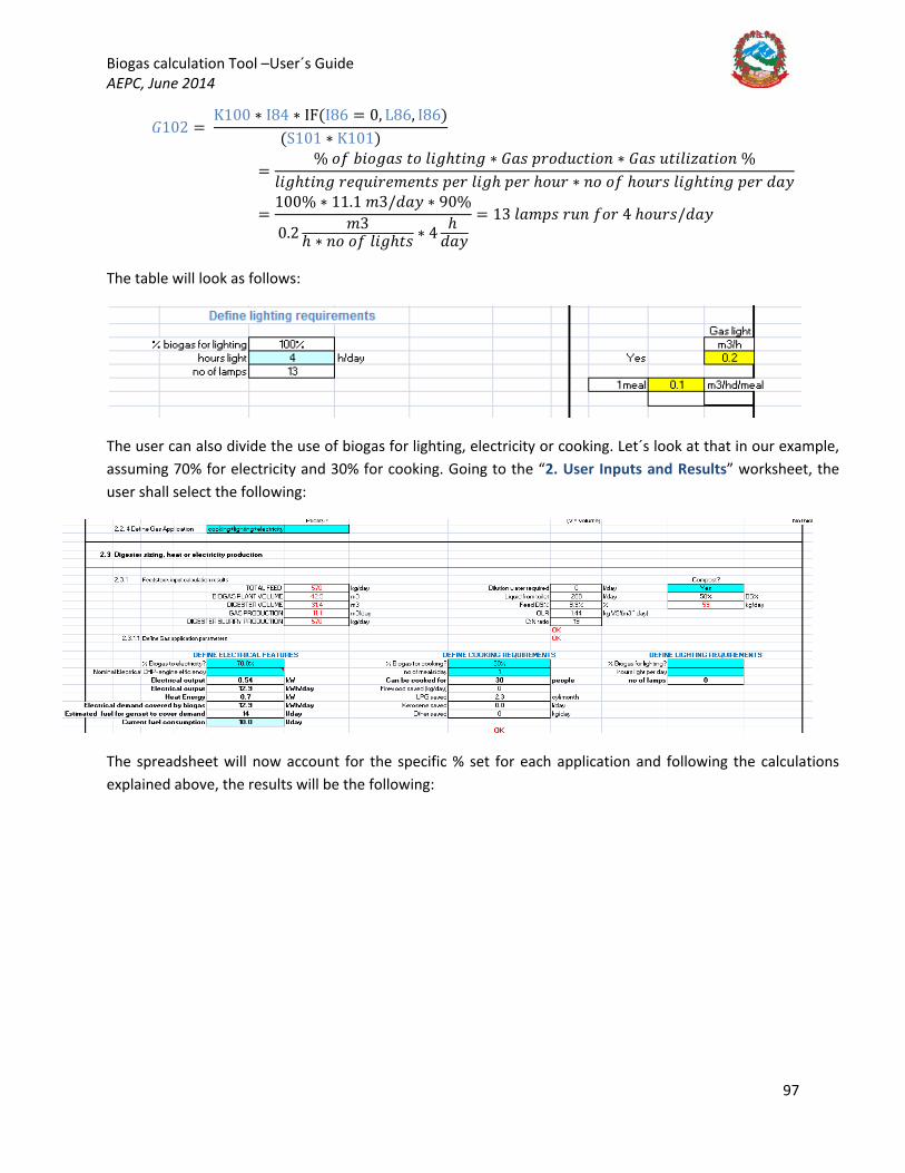
Biogas calculation Tool –User´s Guide AEPC, June 2014
97
𝐺𝐺102 = K100 ∗ I84 ∗ IF(I86 = 0, L86, I86)
(S101 ∗ K101)
=% 𝐵𝐵𝑜𝑜 𝑛𝑛𝐵𝐵𝐵𝐵𝐵𝐵𝐵𝐵𝐵𝐵 𝑤𝑤𝐵𝐵 𝑦𝑦𝐵𝐵𝐵𝐵ℎ𝑤𝑤𝐵𝐵𝑛𝑛𝐵𝐵 ∗ 𝐺𝐺𝐵𝐵𝐵𝐵 𝑝𝑝𝑛𝑛𝐵𝐵𝑦𝑦𝑛𝑛𝑖𝑖𝑤𝑤𝐵𝐵𝐵𝐵𝑛𝑛 ∗ 𝐺𝐺𝐵𝐵𝐵𝐵 𝑛𝑛𝑤𝑤𝐵𝐵𝑦𝑦𝐵𝐵𝑢𝑢𝐵𝐵𝑤𝑤𝐵𝐵𝐵𝐵𝑛𝑛 %
𝑦𝑦𝐵𝐵𝐵𝐵ℎ𝑤𝑤𝐵𝐵𝑛𝑛𝐵𝐵 𝑛𝑛𝑦𝑦𝑒𝑒𝑛𝑛𝐵𝐵𝑛𝑛𝑦𝑦𝑚𝑚𝑦𝑦𝑛𝑛𝑤𝑤𝐵𝐵 𝑝𝑝𝑦𝑦𝑛𝑛 𝑦𝑦𝐵𝐵𝐵𝐵ℎ 𝑝𝑝𝑦𝑦𝑛𝑛 ℎ𝐵𝐵𝑛𝑛𝑛𝑛 ∗ 𝑛𝑛𝐵𝐵 𝐵𝐵𝑜𝑜 ℎ𝐵𝐵𝑛𝑛𝑛𝑛𝐵𝐵 𝑦𝑦𝐵𝐵𝐵𝐵ℎ𝑤𝑤𝐵𝐵𝑛𝑛𝐵𝐵 𝑝𝑝𝑦𝑦𝑛𝑛 𝑦𝑦𝐵𝐵𝑦𝑦
=100% ∗ 11.1 𝑚𝑚3/𝑦𝑦𝐵𝐵𝑦𝑦 ∗ 90%
0.2 𝑚𝑚3ℎ ∗ 𝑛𝑛𝐵𝐵 𝐵𝐵𝑜𝑜 𝑦𝑦𝐵𝐵𝐵𝐵ℎ𝑤𝑤𝐵𝐵 ∗ 4 ℎ
𝑦𝑦𝐵𝐵𝑦𝑦= 13 𝑦𝑦𝐵𝐵𝑚𝑚𝑝𝑝𝐵𝐵 𝑛𝑛𝑛𝑛𝑛𝑛 𝑜𝑜𝐵𝐵𝑛𝑛 4 ℎ𝐵𝐵𝑛𝑛𝑛𝑛𝐵𝐵/𝑦𝑦𝐵𝐵𝑦𝑦
The table will look as follows:
The user can also divide the use of biogas for lighting, electricity or cooking. Let´s look at that in our example, assuming 70% for electricity and 30% for cooking. Going to the “2. User Inputs and Results” worksheet, the user shall select the following:
The spreadsheet will now account for the specific % set for each application and following the calculations explained above, the results will be the following:

Biogas calculation Tool –User´s Guide AEPC, June 2014
98