BIODEGRADABLE COMPOSITE MATERIALS...
22
International Journal of Modern Manufacturing Technologies ISSN 2067–3604, Vol. VI, No. 2 / 2014 63 BIODEGRADABLE COMPOSITE MATERIALS – ARBOFORM: A REVIEW Simona Plăvănescu (Mazurchevici) “Gheorghe Asachi” Technical University of Iasi, Romania, Blvd. Mangeron, No. 59A, 700050 Iasi, Romania Corresponding author: Simona Plăvănescu (Mazurchevici), [email protected] Abstract: Large-scale use of non-renewable resources has led to a significant increase of both the fossil raw materials pricing - a threat to the global economy and the last two decades atmospheric concentration of carbon dioxide – known to affect the global climate. Estimates on the following decades indicate these resources are to be exhausted. Therefore a considerable lowering of the finite resources consumption would prevent the needs of the present from compromising the ability of future generations to meet their own needs. It is known the most of the energy resources, the polymers, and the synthetic organic polymers are derived from fossil fuels such as oil and natural gas. Resources can be maintained if a sustainable future is to be provided by using bio-based materials comprising maximum possible quantity of biomass renewable derivatives. Bioplastics, biofibers, biocomposites and related biomaterials will serve as substitutes for materials and products traditionally made from petroleum resources. To anticipate this need, the German FraunhoferInstitute for Chemical Technologytogether with Tecnaro GmbH Company (founded byJurgenPfitzer and Helmut Nagele) have made studies and developed - based on wood components - a new material which can be processed in the same way as thermoplastics. Arboform is the output of natural fibres, lignin, and additives mixing. It can be obtained by using different types of lignin (30%) extracted out of processes and sources (10 types at least), natural fibres 60% (flax, hemp, sisal, wood) and10% natural additives (softeners, pigments, processing agents, etc.). Arboform is the trade name for a fully biodegradable bioplastic composite also known as “liquid wood”. The material properties – biodegradability and reusability up to ten times without modifications of its features - recommended it to be the near future alternative to all plastic materials. Depending on the quantity of the mixed components, Arboform can be provided in three different variants: LV3 Nature, F45Nature and LV5 Nature. The component elements are mixed and tamped without heating so that to obtain compound granules. This composite material can be injected into moulds by the same injection technology applied to plastics. Arboform is used in the manufacture of a wide range of products, for example: automotive parts, modular circuit boards, watch cases, computer and television set components, etc. In terms of biodegradation, Arboform behaves like wood as it decomposes into water, humus and carbon dioxide proving it to be more eco-friendly than plastics emitting fumes when incinerated. Moreover, Arboform production does not involve supplementary cutting down of trees as lignin is a pulp and paper industry product. Arboform is a high-quality thermoplastic engineering material and is involved in applications requiring state-of- art technology standards. Natural wood positive properties joining the processing features of thermal plastic materials make Arboform the “liquid wood” capable to replace in future times any regular plastic within all activity fields. The hereby study describes the lignin production process, biodegradability against international standard ISO 1485: 2004, Arboform processing, mechanical, electrical and thermal properties of samples, and the microstructural analysis. Key words: production, development, biodegradability, properties, applications. 1. INTRODUCTION Human society has used and continues to widely use plastic materials due to the extensive versatility, cost- effective prices and manufacturing process. Almost all synthetic plastics are obtained out of petroleum and its components. Moreover, most of the plastic materials derived from fossil resources are not biodegradable. Large utilization of plastics and other materials have led over the years to an increase of plastic wastes which are frequently considered to be municipal solid wastes [1]. The main objectives of current fabrication and future development activities consider the following [2]: • Composite materials obtained from natural resources; • Plastic properties: the materials and component parts of the injected product are required to be provided with the plastic material properties verified against the standard feature test procedures; • Use of standard processing technologies and equipment adjusted by small modifications on injection mouldings; • Identification of technical advantages: the materials can be used to obtain high-quality thermoplastics reinforced with natural fibres for applications within consumer products industry, electronics industry, automotive industry, etc.; • Energy conservation: injection at low temperatures
Transcript of BIODEGRADABLE COMPOSITE MATERIALS...
International Journal of Modern Manufacturing Technologies
ISSN 2067–3604, Vol. VI, No. 2 / 2014
63
BIODEGRADABLE COMPOSITE MATERIALS – ARBOFORM: A REVIEW
Simona Plăvănescu (Mazurchevici)
“Gheorghe Asachi” Technical University of Iasi, Romania, Blvd. Mangeron, No. 59A, 700050 Iasi, Romania
Corresponding author: Simona Plăvănescu (Mazurchevici), [email protected]
Abstract: Large-scale use of non-renewable resources has
led to a significant increase of both the fossil raw materials
pricing - a threat to the global economy and the last two
decades atmospheric concentration of carbon dioxide –
known to affect the global climate. Estimates on the
following decades indicate these resources are to be
exhausted. Therefore a considerable lowering of the finite
resources consumption would prevent the needs of the
present from compromising the ability of future
generations to meet their own needs. It is known the most
of the energy resources, the polymers, and the synthetic
organic polymers are derived from fossil fuels such as oil
and natural gas. Resources can be maintained if a
sustainable future is to be provided by using bio-based
materials comprising maximum possible quantity of
biomass renewable derivatives. Bioplastics, biofibers,
biocomposites and related biomaterials will serve as
substitutes for materials and products traditionally made
from petroleum resources. To anticipate this need, the
German FraunhoferInstitute for Chemical
Technologytogether with Tecnaro GmbH Company
(founded byJurgenPfitzer and Helmut Nagele) have made
studies and developed - based on wood components - a
new material which can be processed in the same way as
thermoplastics. Arboform is the output of natural fibres,
lignin, and additives mixing. It can be obtained by using
different types of lignin (30%) extracted out of processes
and sources (10 types at least), natural fibres 60% (flax,
hemp, sisal, wood) and10% natural additives (softeners,
pigments, processing agents, etc.). Arboform is the trade
name for a fully biodegradable bioplastic composite also
known as “liquid wood”. The material properties –
biodegradability and reusability up to ten times without
modifications of its features - recommended it to be the
near future alternative to all plastic materials. Depending
on the quantity of the mixed components, Arboform can be
provided in three different variants: LV3 Nature,
F45Nature and LV5 Nature. The component elements are
mixed and tamped without heating so that to obtain
compound granules. This composite material can be
injected into moulds by the same injection technology
applied to plastics. Arboform is used in the manufacture of
a wide range of products, for example: automotive parts,
modular circuit boards, watch cases, computer and
television set components, etc.
In terms of biodegradation, Arboform behaves like wood
as it decomposes into water, humus and carbon dioxide
proving it to be more eco-friendly than plastics emitting
fumes when incinerated. Moreover, Arboform production
does not involve supplementary cutting down of trees as
lignin is a pulp and paper industry product.
Arboform is a high-quality thermoplastic engineering
material and is involved in applications requiring state-of-
art technology standards. Natural wood positive properties
joining the processing features of thermal plastic materials
make Arboform the “liquid wood” capable to replace in
future times any regular plastic within all activity fields.
The hereby study describes the lignin production process,
biodegradability against international standard ISO 1485:
2004, Arboform processing, mechanical, electrical and
thermal properties of samples, and the microstructural
analysis.
Key words: production, development, biodegradability,
properties, applications.
1. INTRODUCTION
Human society has used and continues to widely use
plastic materials due to the extensive versatility, cost-
effective prices and manufacturing process. Almost
all synthetic plastics are obtained out of petroleum
and its components. Moreover, most of the plastic
materials derived from fossil resources are not
biodegradable. Large utilization of plastics and other
materials have led over the years to an increase of
plastic wastes which are frequently considered to be
municipal solid wastes [1].
The main objectives of current fabrication and future
development activities consider the following [2]:
• Composite materials obtained from natural
resources;
• Plastic properties: the materials and component
parts of the injected product are required to be
provided with the plastic material properties verified
against the standard feature test procedures;
• Use of standard processing technologies and
equipment adjusted by small modifications on
injection mouldings;
• Identification of technical advantages: the materials
can be used to obtain high-quality thermoplastics
reinforced with natural fibres for applications within
consumer products industry, electronics industry,
automotive industry, etc.;
• Energy conservation: injection at low temperatures

64
(< 160°C), thermal stability at 95°C at least or even
105°C [2].
Lignin is a natural polymer and main component of
biomass, with content in trees and other woody-plants
up to 30% and represents the starting point for a new
class of thermoplastics made of renewable resources [1].
The growing interest in green ecology and ecological
sustainability has also contributed to directing
attention to biomass and particularly to
lignocelluloses stock as a promising, renewable, and
extended resource for biopolymers [3].
Lignocellulosic biomass comprises three main
biopolymers: cellulose, hemicelluloses and lignin [4].
Lignin is now considered the main aromatic
renewable resource as it is an excellent alternative
feedstock for the elaboration of chemicals and
polymers. As a highly abundant biopolymeric
material, lignin and cellulose represent together one
of the major components. Each year, large quantities
of lignin are available from numerous pulping
processes such as paper and biorefinery industries.
The extraction of lignin from lignocellulosic biomass
represents the key point to its large use for industrial
applications.
Lignin is a major component of woody plants as it
provides strength and adequate structure to the cell
walls, controls the fluid flow rate, and protects from
biochemical stress by enzymatic degradation of other
components. [3].
Although the quantity of lignin reaches 50 million
tons per year [5] only a small amount up to 2%is
recovered and used for a wide range of products or
chemical materials such as Arboform [6]. The rest of
98% are used as fuel/ raw material in the paper mills.
Nevertheless, there are enough reasons and good
arguments to use this promising resource in industry
applications [7].
Lignin is formed by photosynthesis, makes up about
15-25% of the substance of every wood or plant, and
is the second abundant organic polymer on Earth as
shown in Figure 1 [1, 7].
Fig. 1. Simplified structure of wood
Within last years, a number of new initiatives have
been performed for a more efficient management of
lignin wastes produced by chemical delignification
and wood industry. Sulphite substances and the
components of these lignosulfonates are the most
used wastes derived from paper and cellulose
industry [2].
Different types of lignin are available as more than 20
variants are frequently produced. For a lignin-matrix
material such as Arboform, the input and lignin
quality are highly important [10]. The near infra-red
spectroscopy (NIRS) provides online control of
thermoplastic processing operations. The NIRS
method has been introduced to measure the lignin
content [8, 9]. The infra-red spectrum of some types
of lignin is indicated in Figure 2. As the differences
are not clear in the main band between 1400 and
1500 nm the structure is provided by physical
properties, i.e. the particle size.
Fig. 2. Different types of NIR spectra, [2]
Following a statistical analysis involving multiple
variants [11, 12] of the principal component analyzed
(PCA) by NIR, the differences between the studied
lignin types graphically represented in Fig.3 can be
clearly distinguished.
Fig. 3. Main component analysis (PCA), [2]
Lignin has been determined by NIR/IR spectroscopy,
thermal analysis methods and scanning electron
microscopy (SEM). The IR/ NIR spectra are similar

65
to the spectra of other lignin types (Fig. 4).
Nevertheless, the chemometric analyses (principal
components analysis, PCA and partial least squares
regression / multiple linear regression, PLS) can
clearly indicate the difference between HPH -lignin
(high pressure hydrolysis) and other types, as shown
in Figure 4.
Fig. 4. IR analysis of two samples comparing HPH
Aquasolv lignin andOrganosolv lignin, [2]
Figure 5, [14] presents an exhibits the most frequent
chemical process used for lignin separation (HPH).
Almost forty years ago, the American scientists have
taken the first steps towards stopping the human
dependence on plastic products. Tecnaro German
company has succeeded in manufacturing a product
that looks like wood, has woody-structure, can be
moulded/ injected by the same procedure as that of
plastic materials, and, in addition to these properties,
is biodegradable and known as “liquid wood” 17].
In addition, many residues of agricultural products
that are currently unused contain substantial amounts
of lignin (Table 1, [13]).
Concerning the natural fibres reinforcing process, the
new biofibers and wood fibres could be used (Figure
6, [15, 16]).
Fig. 5. Lignin separations, [14]
Fig. 6. Reinforcing natural fibers, [15, 16]
Table 1. Content of lignin, hemicelluloses, cellulose, nitrogen and ash from different rests and residues of
plants and fruits [2, 13]
Lignin Cellulose Hemi-cellulose Nitrogen Ash
Meal from maize (hominy) 2.0 11.0 42.0 1.84 1.0
Malt sprouts hulls 3.0 15.0 28.0 4.5 7.0
Brewers grains, dehydrate 6.0 18.0 22.0 4.16 4.0
Crape stems 12.0 - - < 0.5 -
Straw from rice 12.5 32.1 24.0 - 17.5
Coffee ground 15.0 - 9.0 0 2.0
Hay, weathered 15.0 30.0 13.0 1.6 8.0
Straw from Soybean 16.0 38.0 16.0 0.83 6.0
Bamboo 20.1 - 19.6 - 3.3
Hulls from peanuts 23.0 42.0 9.0 1.25 4.0
Cocoa bean 25.0 - - 2.56 -
Olive waste 28.0 - - 0 -
Grape pomace 38.0 19.0 1.0 0 10.0
Fruit pits 40.0 - - - -

66
"Liquid wood” is available in three different versions:
ARBOFORM®Liquid wood (based on lignin, organic
additives and natural fibers), ARBOBLEND®plastic
composite with wood (its content is based on
biopolymers degree, e.g.: lignin, starch, natural
resins, wax and cellulose), ARBOFILL®biopolymeric
composite (polymers and natural fibres-based
compound provided with natural cork aspect) [6, 18].
Arboform has been developed some years ago, in
1998, when FraunhoferInstitute for Chemical
Technology together with Tecnaro GmbH, Germany
have investigated and developed out of wood
composing elements a new compound able to be
processed like a thermoplastic material. The new
product can be manufactured by using multiple types
of lignin (30%) from different processes or sources
(more than 10 types), 60% organic fibers (flax, hemp,
sisal, wood) and 10% organic additives (plasticizers,
pigments, processing agents, etc.)[2, 6, 19].Arboform
is available in three product variants according to the
corresponding quantities of mixed components: LV3
Nature, F45Nature and LV5 Nature [6]. Table 2
bellow indicates the possible composition alternatives [2].
Table 2.Variations in composition, [2]
Matrix
Lignin 30% 60%
Fibre reinforcement (loose
fibres)
hemp (e.g. H1) 10% 60%
10% 60% flex (e.g. F4)
Additives
processing aids (PrAi) 0% 10%
impact modifier 0% 20%
flame retardants 0% 15%
The variations of Arboform composition in what
concerns both quality and quantity allow adjustments
of strength, rigidity, dimensional stability with
varying temperatures and other material properties in
order to comply with specific product requirements
[20, 21]. Arboform degrades (Figure 7) just like wood, into
water, humus, and carbon dioxide, therefore making
it more eco-friendly than the fume-emitting burning
of plastics [22]. Moreover, because lignin is a by-
product of the paper making industry, Arboform
production does not require additional cutting down
of trees. Every year, the paper and pulp industry
alone produces 130 million kg of lignin [24].
Arboform is a high-quality thermoplastic material
made exclusively from renewable resources, with no
adverse effects on human health.
Researchers have identified no changes of the
material mechanical properties, i.e. behaviour in fire
and durability, as the material is renewable
[24].Arboform behaves like any petrochemical plastic
material which means it can be heated and moulded/
injected into a broad range of complex mouldings [25].
Being made one hundred percent from renewable
resources, an Arboform product, just like wood-based
products, can be disposed by incineration at the end
of its useful life. Therefore, the incineration of the
product will emit into the atmosphere just the same
amount of CO2 that the plant previously took from the
atmosphere while it was growing. So this is a closed
CO2 cycle without any accumulation of CO2 in
atmosphere and, hence, no more adding to the
greenhouse effect [26].
The only drawbacks to be considered for liquid wood
could be the weight, much higher than of the ordinary
plastics, and the production costs, almost double that
of the most common plastic, polypropylene.
Fig. 7. Biodegradation of "liquid wood" [23]
67
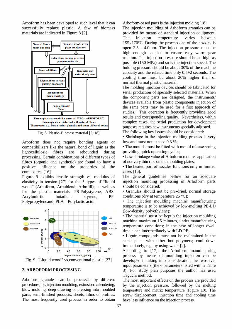
Arboform has been developed to such level that it can
successfully replace plastic. A few of biomass
materials are indicated in Figure 8 [2].
Fig. 8. Plastic–Biomass material [2, 18]
Arboform does not require bonding agents or
compatibilizers like the natural bond of lignin as the
lignocellulosic fibres are rebounded during
processing. Certain combinations of different types of
fibres (organic and synthetic) are found to have a
positive influence on the properties of the
composites. [16].
Figure 9 exhibits tensile strength vs. modulus of
elasticity in tension [27] for the 3 types of “liquid
wood” (Arboform, Arboblend, Arbofill), as well as
for the plastic materials: PS-Polystyrene, ABS-
Acrylonitrile butadiene styrene, PP-
Polypropyleneand, PLA – Polylactic acid.
Fig. 9. "Liquid wood" vs.conventional plastic [27]
2. ARBOFORM PROCESSING
Arboform granules can be processed by different
procedures, i.e. injection moulding, extrusion, calendering,
blow molding, deep drawing or pressing into moulded
parts, semi-finished products, sheets, films or profiles.
The most frequently used process in order to obtain
Arboform-based parts is the injection molding [18].
The injection moulding of Arboform granules can be
provided by means of standard injection equipment.
The injection temperature varies between
155÷170°C. During the process one of the nozzles is
open 2.5 - 4.0mm. The injection pressure must be
high enough so that to ensure easy worm gear
rotation. The injection pressure should be as high as
possible (150 MPa) and so is the injection speed. The
holding pressure should be about 30% of the machine
capacity and the related time only 0.5÷2 seconds. The
cooling time must be about 20% higher than of
normal thermal plastic material.
The molding injection devices should be fabricated for
serial production of specially selected materials. When
the component parts are designed, the instruments/
devices available from plastic components injection of
the same parts may be used for a first approach of
studies. This operation is frequently providing good
results and corresponding quality. Nevertheless, within
complex cases, the serial production for development
purposes requires new instruments specially adjusted.
The following key issues should be considered:
• Shrinkage in the injection molding process is very
low and must not exceed 0.3 %;
• The moulds must be fitted with mould release spring
providing quick operating cycles;
• Low shrinkage value of Arboform requires application
of not very thin ribs on the moulding plates;
• The heated port of nozzles functions only in limited
cases [16].
The general guidelines bellow for an adequate
injection moulding processing of Arboform parts
should be considered:
• Granules should not be pre-dried, normal storage
conditions (dry at temperature 25 °C);
• The injection moulding machine manufacturing
temperature is to be achieved by low-melting PE-LD
(low-density polyethylene);
• The material must be keptin the injection moulding
machine maximum 15 minutes, under manufacturing
temperature conditions; in the case of longer dwell
time clean intermediately with LD-PE;
• Lignin-compounds must not be maintained in the
same place with other hot polymers; cool down
immediately, e.g. by using water [2].
According to [17], the Arboform manufacturing
process by means of moulding injection can be
developed if taking into consideration the two-level
input parameters (the 6 parameters listed within Table
3). For study plan purposes the author has used
Taguchi method.
The most important effects on the process are provided
by the injection pressure, followed by the melting
temperature and matrix temperature (Figure 10). The
screw displacement, injection time and cooling time
have less influence on the injection process.

68
Table 3.The level values of input parameters
Input
parameter
levels
melt
temperature
[°C]
injection
time
[s]
cooling
time
[s]
screw
displacement
[mm]
injection
pressure
[MPa]
matrix
temperature
[°C]
First level 165 9 18 60 80 50
Second level 180 11 25 80 100 80
Fig. 10. Input parameters average effects on Indentation Modulus: 1 - Arboform L, V3 Natura;
2 - ArboblendV2 Natura; 3 – Arbofill Fitchie [17]
3. MECHANICAL PROPERTIES
3.1 The Influence of the Fibre Content
The Arboform formula indicates a major dependence
of the mechanical properties on the content of fibres
(particularly hardwood fibres), which ensures a wide-
range variation of the injection moulded parts
material properties. Figure 11 indicates a significant
increase of the tensile strength related to the fibres
content within the composition using hardwood
fibres. A 45% approximate content of fibres can
provide a good balance between stiffness and
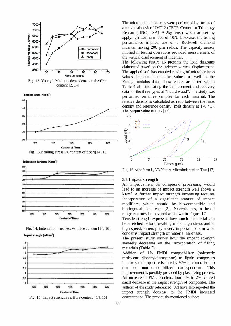
strength. In the case of other fibre types (Figure 12),
substantial high modulus is reached even though the
fibre content might be lower [2, 14, 16].
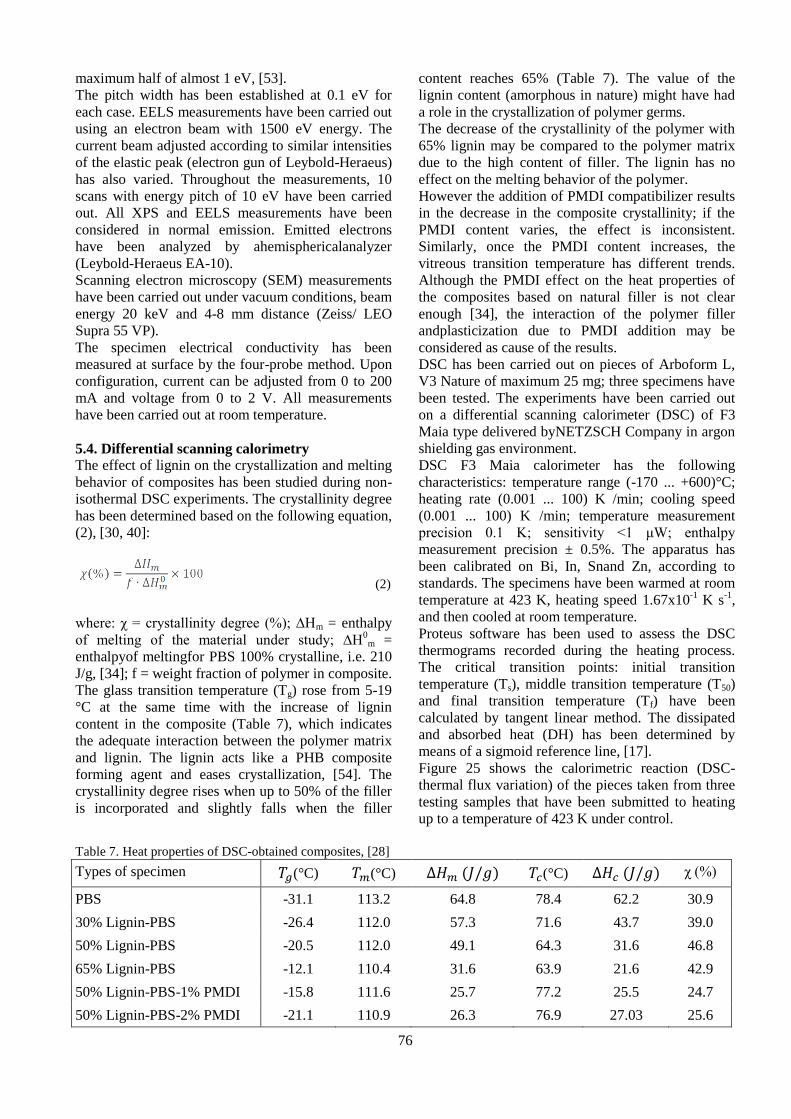
The bending stress (Figure 13) registers an increase
due to the content of fibers. Taking into consideration
the same percentage, approximately 45%, the
bending stress value is higher than the double value
of tensile strength.
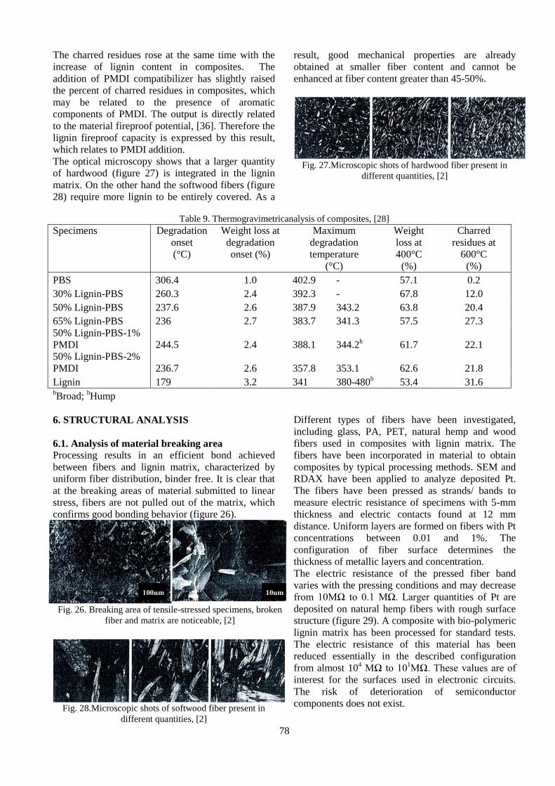
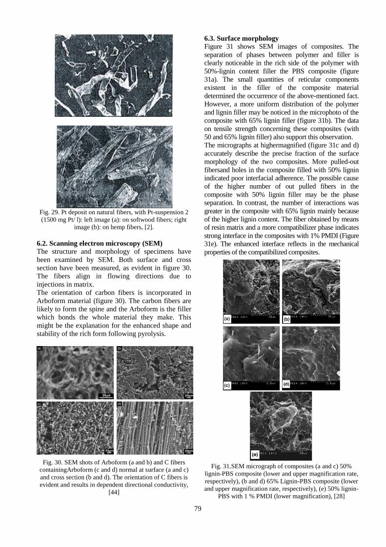
Concerning the indentation hardness (Figure 14) and
impact strength (Figure 15) in relation to the fibre
content, the dependence is less pronounced. The
mechanical properties values are very close to those
of wood-like plastics with commercial lignin.
Fig. 11. Tensile strength vs. Fibre content [14, 16]
3.2 Microindentation
The Arboform microindentation results are listed in
Table 4, according to the authors indicated in [17].
Figure 6 exhibits the microindentation variation values.
69
Fig. 12. Young’s Modulus dependence on the fibre
content [2, 14]
Fig. 13.Bending stress vs. content of fibers[14, 16]
Fig. 14. Indentation hardness vs. fibre content [14, 16]
Fig. 15. Impact strength vs. fibre content [ 14, 16]
The microindentation tests were performed by means of
a universal device UMT-2 (CETR-Center for Tribology
Research, INC, USA). A 2kg sensor was also used by
applying maximum load of 10N. Likewise, the testing
performance implied use of a Rockwell diamond
indenter having 200 µm radius. The capacity sensor
implied in testing operations provided measurement of
the vertical displacement of indenter.
The following Figure 16 presents the load diagrams
elaborated based on the indenter vertical displacement.
The applied soft has enabled reading of microhardness
values, indentation modulus values, as well as the
Young modulus data. These values are listed within
Table 4 also indicating the displacement and recovery
data for the three types of “liquid wood”. The study was
performed on three samples for each material. The
relative density is calculated as ratio between the mass
density and reference density (melt density at 170 °C).
The output value is 1.06 [17].
Fig. 16.Arboform L, V3 Nature Microindentation Test [17]
3.3 Impact strength
An improvement on compound processing would
lead to an increase of impact strength well above 2
kJ/m2. A further impact strength increasing requires
incorporation of a significant amount of impact
modifiers, which should be bio-compatible and
biodegradable,at least [2]. Nevertheless, a broad
range can now be covered as shown in Figure 17.
Tensile strength expresses how much a material can
be stretched before breaking under high stress and at
high speed. Fibers play a very important role in what
concerns impact strength or material hardness.
The present study shows how the impact strength
severely decreases on the incorporation of filling
materials (Table 5).
Addition of 1% PMDI compatibilizer (polymeric
methylene diphenyldiisocyanate) to lignin composites
improves the impact resistance by 92% in comparison to
that of non-compatibilizer correspondent. This
improvement is possibly provided by plasticizing process.
An increase of PMDI content, from 1% to 2%, caused
small decrease in the impact strength of composites. The
authors of the study referenced [32] have also reported the
impact strength decrease to the PMDI increased
concentration. The previously-mentioned authors

70
Table 4. Presentation of study results [17]
Parameter
Material Material
Displacement
(µm)
Recovery
(µm)
Micro
Hardness
(GPa)
Indentation Modulus
(GPa)
Load (N)
Reduced Young's
Arbofill
Fitchie
Sp. 1 98.374 42.907 0.079393 0.805 0.826 8.941
Sp. 2 94.205 35.604 0.0811 1.011 0.983 8.942
Sp. 3 110.195 59.24 0.07364 0.591 0.575 8.934
Arboblend V2
Nature
Sp. 1 60.051 18.057 0.140298 2.617 2.547 8.965
Sp. 2 63.996 21.793 0.128738 2.429 2.363 8.975
Sp. 3 75.957 26.985 0.110428 1.419 1.38 8.954
Arboform
L, V3 Nature
Sp. 1 42.575 12.673 0.231877 3.078 2.997 8.970
Sp. 2 46.121 16.005 0.197364 3.541 3.449 8.978
Sp. 3 61.361 24.551 0.150256 1.844 1.794 8.972
Fig. 17. Dependence of the impact strength on the amount
of impact modifier used [2]
registered a negative effect at 1% PMDI during the
use of bamboo cellulose composites. Moreover, the
same effect was also observed at 2% content for the
composites filled with lignin and presented in the
study referenced in [28].
Similar tendency has been registered for the impact
strength of notched Izod of the lignin composites - PP
(polypropylene) [29]. It has been reported that
incorporation of lignin, which is an unstable material,
causes the composites impact strength to decrease.
The incorporation of agrofibres also determines
decrease of composites impact strength [30, 31].
Table 5. Tensile modulus, flexural strength, HDT (Heat Deflection Temperature) and impact properties of composites [28]
Specimen label Tensile
strength
(MPa)
Tensile
modulus
(GPa)
Elongation
at break
(%)
Flexural
strength
(MPa)
Flexural
modulus
(GPa)
Impact
strength
(J/M)
HDT
(°C)
PBS 35±1.5 0.6±0.01 122±21 28±0.4 0.6±0.01 40±8.4 78±1.9
30% Lignin-PBS 26±1.8 1.1±0.03 4.6±0.3 40±0.5 1.1±0.01 29±1.0 83±3.0
50% Lignin-PBS 29±3.4 2.3±0.35 2.0±0.8 46±0.3 2.2±0.03 15±0.9 86±3.1
65% Lignin-PBS 39±1.1 3.3±0.04 1.5±0.1 52±1.1 3.8±0.15 11±0.9 85±0.6
50% Lignin-PBS-1%
PMDI
37±6.1 2.0±0.03 3.1±1.3 68±1.8 2.3±0.07 29±2.3 90±1.9
50% Lignin-PBS-2%
PMDI
42±4.7 1.9±0.19 4.3±0.7 66±0.7 2.1±0.03 24±3.7 94±1.6
3.4 Tensile strength
Table 5 shows the composite tensile properties. It is
noted that the composite tensile strength has initially
reduced by 30% in the case of 30% incorporated
lignin and then has gradually risen with the increase
of lignin content to 65% (table 5). The composite
tensile strength has also decreased with the increase
of filler content (agro fibers) in the biodegradable
polymers such as PLA (polylactic acid) and PBS
(polybutylene succinate) [30, 31]. The result has been
ascribed to poor interfaceadhesion between the
hydrophilic filler and hydrophobic polymer matrix.
However, the tensile properties of composites have
improved in the case of higher lignin content (65%).
Therefore, the tensile strength has risen by over 10%
of 50% lignin-filled composites and the resistance
was about 13% higher than the value of pure

71
polymer.
The increase of tensile strength in the case of higher
lignin content points out the reinforcement effect of
lignin in PBS polymer. This can be ascribed to the
similarity in the solubility parameter of lignin and
PBS, cross-linking capacity and lignin adhesive
properties.
Viscosity in the composite melt has been noticed
during processing the composites with 65% lignin
filler. However, composite melt at 30% and 50%
lignin content has been relatively less viscous. The
above mentioned result may be ascribed to the lignin
cross-linking capacity that grew with the increase of
lignin content in the composite materials.
The composite elasticity modulus increases
gradually with the rise of lignin content in the
composite materials. The improvement of
composite properties shows the possible polar-
polar interaction between lignin and polyester
matrix. The improvement of tensile strength of
hydroxypropyl lignin and polyethylene mixture
with an addition of vinyl acetate, polar component
in the polyolefin non-polar matrix, also stands for
the interaction concept [33]. The authors have
interpreted the interaction due to the presence of
polar carbonyl group [33]. Therefore, formation of
hydrogen bonds might be possible between the
carbonyl group of polyester matrix and the
hydroxyl group of lignin.
Based on adequate processing and combination of
properties, 50% filler-based composites have been
selected for PMDI compatibilizer incorporation. The
incorporation of 1% and 2% PMDI has increased
tensile strength by 27% and 44% in the non-
compatibilized composites and has been almost 7.5%
and 22% greater than the value of the pure/clean
polymer (table 5). These results back up the
conclusion that PMDI enhanced interface adhesion in
composites [32, 34].
PMDI addition leads to the formation of (-HN-COO-)
urethane, bond created due to the reaction between –
NCO group ofPMDI and –OH group of lignin [35].
Furthermore, the urethane bond may lead to the
secondary intermolecular join (e.g. hydrogen bonds
between N-H group of urethane bond and carbonyl
bond of polyester, [35]) that might be the reason for
the enhancement of interface adhesion of PMDI
compatibilizer composites.
The composite modulus slightly decreases with 1%
PMDI addition (table 5). The composite modulus has
been gradually reduced with rise of PMDI
concentration from 1% to 2%. The modulus decrease
may be ascribed to the plasticization of composite
materials due to PMDI addition. The humidity in bio-
filler has been reported to respond to PMDI and to
produce amine or urea compounds.
The above mentioned compounds plasticize the
composites [34], resulting in modulus decrease and
elongation increase. The stress – strain curves of
composites are presented in figure 18.
The figure also depicts the fragile behavior of
composites. The materials tensile stress decreases with
the incorporation of filler and is slightly improved by
PMDI addition. Table 5 shows how breaking elongation
value reduces with filler incorporation, and slightly
increases with PMDI addition. PBS is extremely ductile
polymer; the elongation percentage reduces
significantly by 10% the moment the bio-filler is added
[36]. Similar trends of properties upon PMDI addition
are to be observed for sugar beet pulp in the polyactide-
based composite [34].
The mixture rule is contained in equation (1) used to
determine the composite modulus, and is usually
applied to randomly oriented short-fiber composites.
[30].
(1)
where: Ec, Em, Efrepresent elasticity moduli of
composite, polymer matrix and filler material
(lignin), respectively. The lignin modulus 6.27 GPa
[6] has been considered to calculate the composite
modulus; VmandVf represent the volume fraction of
polymer matrix and filler material, respectively.
Factor "k" (contribution of fiber length and
orientation) has been used to match the data.The
fraction related to fiber and matrix volume has been
calculated using PBS (1.26 g/cm3) and lignin (1.34
g/cm3) density.
Table 5 shows the correlation between the theoretical
modulus and the composite modulus determined
experimentally. The increase of modulus with the
growth of lignin content is evident in figure 19.
The theoretical modulus calculated by mixture rule
has been greater than the composite modulus
experimentally determined. Considering the matching
parameter k = 0.67, the theoretical modulus matches
exactly with the experimental modulus of the 50%
lignin filled composite. However, the modulus values
obtained in the case of composites with 30% and 65%
lignin filler have been slightly lower and greater than
the values of the calculated modulus.
Considering the random orientation of wheat straw
fibers, the authors have reported a fiber efficiency
coefficient of k = 0.9 [31]. However, lignin grains
(with fine milled 45% bio-fibers, lignin particles and
other additives [6.38]) have been used as filler
material instead of bio-fibers. Therefore, the value of
the coefficient "k" = 0.67 is reasonable enough. The
interaction polymer – lignin (that is not considered in
the equation) may result in low values of the modulus
for composite with 30% lignin content, high values of
the composite with 65% lignin content and modulus
theoretical values.

72
Fig. 18. Stress – strain curve of composites: (i) PBS pure
specimen, (ii) 30% lignin PBS composite, (iii) 50% lignin
PBS composite, (iv) 65% ligninPBS composite, (v) 50%
ligninPBS composite with 1% PMDI , (vi) 50% ligninPBS
composite with 2% PMDI, [28]
Fig. 19. Correlation analysis: experimental elasticity
modulus and mixture rule (ROM), [28]
3.5 Mechanical properties: bending
As can be seen from table 5, the bending strength and
the coefficient of elasticity of composites has
gradually increased with the lignin content. The
bending strength and the coefficient of elasticity rose
from 41% to 84% and from 81% to 503%,
respectively with the increase of the lignin content
30-65 %. The polar bio-filler are considered to be
compatible with the polar polymers that enhance the
two phase blending possibility and promote a better
interfacial morphology [28].
However, the difference between the bending
strength and the coefficient of elasticity variation has
not been clearly understood. The mechanical
behavior of the material under tension and bending
stress may be the cause of the variation. The addition
of 1% PMDI improves the bending strength by 48%
as compared to the non-compatibilized material, and
by 143% as compared to the pure polymer (table 5).
The stress transfer from the matrix to the filler and
towards a compatibilizer-modified interface is
considered to be the cause of the significant
improvement. The coefficient of elasticity of the
composites with 1% compatibilizer agent remained to
almost the same level of the coefficient of the non-
compatibilized materials (table 5). The increase of
PMDI to 2% has slightly decreased the bending
strength and the coefficient of the composites. This
result may be ascribed to the effect resulted from
different concurrent reactions, such as the formation
of urethane bond and secondary hydrogen bonds [28].
3.6 Dynamic mechanical analysis
(DMA and HDT analysis)
The dynamic mechanical analysis (DMA) is widely
used to investigate the structure, elasticity and viscosity
of the composite materials. The delay measurement
(Tanδ) provides information on glass vitreous transition
temperature, and the build-up modulus provides data on
stiffness. The build-up modulus records the elasticity
component of the material complex modulus. Figure
20a shows the storage and loss moduli and tanδ of the
composites according to temperature. The polymer and
composites storage modulus decreased with the increase
of temperature (figure 20a). The reduction of the storage
modulus with the temperature may be ascribed to
polymer softening and to the fact that the mobility of the
polymer matrix chain increases at higher temperatures.
As compared to pure PBS, the composite storage
modulus at room temperature (25 °C) grew by 96-495%
to 30-65% at the same time with the increase of lignin
content. Similar results have been noticed in the case of
agro-flour contained by the biodegradable composites
[30]. The composite storage modulus remained almost
constant to 1% PMDI addition. However, the storage
modulus increases and decreases with the 2% PMDI
content. This remark may be ascribed to different
concurrent reactions caused by PMDI addition.
The decrease of the storage modulus represents the
contribution of the viscosity to the material complex
modulus. At room temperature the loss modulus of
certain composites has increased with the growth of
filler content (figure 20b). However, a very small
difference has been identified in the loss modulus near
the glass vitreous transition temperature [37]. The glass
vitreous transition temperature (Tg) given by the peak of
the loss modulus (figure 20b) grew with the increase of
the lignin content. Two peaks may be noticed in the
thermogram of the composite with 65% lignin: the first
peak corresponds to the Tg polymeric phase and the
second represents the filler (due to the high filler
content). The compatibilized addition to the PBS
composite with 50% lignin filler has slightly decreased
because of the glass vitreous transition temperature.
The material delay behavior is measured by Tanδ
magnitude, which represents the relationship between
the loss modulus and storage modulus or between the
dissipated and stored energy during the adynamic
loading cycle [38].Tanδ decreased with the filler
incorporation (figure 20c). The result shows that the
addition of filler decreased the molecular mobility of
the composite materials and that the mechanical

73
losses contribute to passing over the inter-friction
between the molecular chains that are also reduced. A
similar remark has been reported with regard to
reinforcement of the composites with PBS [38] and
PLA [30] bio-fibers.
Fig. 20. Dynamic mechanical analysis: (a) storage
modulus, (b) loss modulus (c) Tanδof composites. (i) PBS
pure sample, (ii) 30% lignin- PBScomposite, (iii) 50%
lignin- PBS composite, (iv) 65% lignin-PBScomposite, (v)
50% lignin-PBS composite with 1% PMDI , (vi) 50%
lignin-PBS composite with 2% PMDI, [28]
The interaction between PBS matrix and lignin can be
understood by the increase of the temperature of
Tanδpeak (often mentioned as vitreous transition
temperature, Tg) and enlargement of thermogramsTanδ as
a result of lignin incorporation. Two effects are
considered to determine the cause of Tg increase. The
first effect may be the creation of an amorphous
component in the composite structure in which both
polymer and filler coexist in a closely associated
condition and contribute to the reduction of free volume
in the composites. As a result Tg increases. Tg may also
increase due to secondary bonds that act as quasi-
crossed (reticular) bonds and limit the Brownian motion
of long chains [33]. Firstly, composite Tg has increased
to 1% and then decreased by almost 6°C when 2%
PMDI has been added. This fact may be ascribed to
such effects as improvement of interaction and plasticity
due to PMDI added. The interaction between polymer
and filler improves Tg, and plasticity decreases Tg in a
material.
Heat deflection temperature (HDT) is a measure of the
material dimensional stability under a certain load and
temperature. This is considered essential requirement of
the property for a wide range of material applications.
Table 5 shows HDT values for pure PBS and all
composites. HDT of composites grows with the increase
of lignin content to up to 50% of weight and stays
almost unmodified with the increase of lignin up to
65%. The improvement of HDT has also been noticed
in the composites with bio-fiber reinforcement [39, 40],
which may be ascribed to high crystallization of bio-
composites [39] in comparison with pure composites.
The incorporation of compatibilizer improves HDT of
composites as a result of interfacial adhesion
enhancement [39].
4. ELECTRICAL PROPERTIES
4.1. Electrical conductivity with nanoparticles There are various approaches to increase electrical
conductivity of plastics by means of nanoparticles [41,
42]. Precipitation of metallic nanoparticles in the case of
reinforced fibers is an efficient approach to achieve
good electrical conductivity at low concentrations. To
avoid oxidation during extrusion and mould injection
processing, Pt has been selected as metallic particles
model. Pt stable suspensions (delivered by Tsutomu
Sakai, KR1 Inc, Japan) [43] have been applied in two
variants of concentration: suspension 1 (150 mg Pt/ L)
and suspension 2 (1500 mg Pt/ L). Both variants contain
2-5 nm sized particles (figure 21). The fibers have been
immersed in suspensions and precipitated particles in a
rotary evaporator with vacuum system to remove liquid
medium at 70 °C. Different types of fibers have been
investigated, including glass fibers, PA (polyamide),
PET (polyethylene terephthalate) and natural hemp and
wood fibers, by means of composites with lignin
matrices [44].
a)

74
b)
Fig. 21. Deposit of Pt on natural fibers; left image (a): with
suspension 1 (150 mg Pt/ l) orsoftwood fibers; right image
(b): suspension 2: (1500 mg Pt/ l) on hemp fibers [2]
4.2. Electron energy loss spectrometry (EELS) EELS measurements (figure 22) indicate a change in the
hybridization of a structure rich in sp2 following
pyrolysis. This can be read from the presence of
plasmon-π at 6 eV electron energy loss [45].
Unpyrolyzed free fibers generate severe loads during
measurements, and intensity drops suddenly with every
scan.
Therefore, figure 22a shows only the first several
scans, the average and the explanations of the noise
weak signal in relation to the measurements
performed on materials containing carbon fibers. The
signal of the carbon fiber containing compounds has
been stable throughout the measurement period.
Following pyrolysis at 1200°C, plasmon-π rises and a
sharp structure is generated, which indicates the
conversion to a similar graphitic material.
Furthermore, plasmon-π is found at an energy loss of
almost 25 eV, usually measured for graphite [46].
This fact supports the existence of a graphitic
structure.
Fig. 22. EELSspecter of unpyrolyzedArboformwithout (a)
and with carbon fibers (b) as compared with
pyrolyzedArboform with carbon fibers (c), [44]
4.3. Electrical conductivity
Electrical conductivity has been determined by means
of various Arboform F45 samples that have been
submitted to pyrolysis at different temperatures. For
purposes of comparison, the conductivity of
Arboform with 25% carbon fibers, submitted to
pyrolysis up to 1200 °C, has also been tested. The
electrical conductivity values did not fluctuated
significantly during different sample measurement
points; thus conductivity is isotropic. Table 6
summarizes the average values of the electrical
conductivity.
Table 6. Electrical conductivity ofpyrolyzedArboform F45
sample measured by four-probe method [44]
Sample Pyrolysis
Electrical conductivity
(S cm-1
)
F45 600 °C 0.49
F45 1000 °C 7.5
F45 1200 °C 0.0053
F45 with 25%
C-fibers 1200 °C
164 (along fiber
direction)
F45 with 25%
C-fibers 1200 °C
44.6 (cross fiber
direction)
Electrical conductivity varies with pyrolysis
temperature. Furthermore, the presence of carbon
fibers is important. UnpyrolyzedArboform F45 is a
polymer, an insulating material that cannot be
characterized by means of four-probe method.
Arboform F45 pyrolyzed at 600 °C is a weak
conductor. The sample/ specimen pyrolyzed at 1000
°C, with 7.5S cm-1
conductivity, are an example of
reasonable conductivity. The use of carbon fibers
increases drastically the conductivity. The measured
conductivity was much greater along than across fiber
direction. The value of electrical conductivity of the
sample without carbon fibers, pyrolyzed at 1200 °C is
very low. This low value is ascribed to the fact that
pyrolysis at high temperature results in porous
material due to pyrolysis gas diffusion. The holes
created by gas diffusion might disappear in future in
the case of pyrolysis process optimization.
5. THERMAL PROPERTIES
5.1. Fire resistance
The realization of certain fire retardant class is
difficult to achieve when only bio-base or at least bio-
compatible substances are used. To obtain relevant
values, the additive quantities required are high and
may negatively influence frequently the mechanical
properties. Only halogen free additives, which impact
on environment is justified, are used. In the case of
synthetic plastics, such as large polypropylene
quantities, these types of additives must be used to

75
fulfill some basic criteria. Arboform composite with
lignin matrix requires smaller quantities of fire
retardant substance to achieve fire/ fire-set rating: UL
V1 (Underwriters Laboratories –combustion stop
within 30 seconds for vertical specimen) and UL
HB(Underwriters Laboratories – slow combustion for
horizontal specimen). The mechanical properties are
simply reduced by 10-20%.
UL V0 (Underwriters Laboratories –combustion stop
within 10 seconds for vertical specimen) and UL HB
rating are also possible, [2].
5.2. Pyrolysis of porous carbonic structures
Arboform submitted to pyrolysis leads to porous
carbonic structures that can be used for various
applications [47]. The injected parts submitted to
pyrolysis might allow the realization of complex
forms created in mould. The result is a graphical
structure (figure 23) with high porosity (figure 24).
Moreover, the high degree of porosity might allow
the pyrolyzedArboform to act as isolating material or
wear resistant material and to remain thermally stable
at high temperatures.
Fig. 23.Pyrolysis of Arboformleads to a stable component
that can be used for various carbon applications [2]
Fig. 24.Porous structure of pyrolyzedArboform [2]
Ceramics (e.g. metallic carbide) can be obtained in
the case of metallic-organic compounds infiltration to
produce a metal or a metal oxide layer in
decomposition. A new possibility might be deposit of
Si (silicon) in cyclopentasiloxane in accordance with
the description of glass fibers [48, 49]. The electrical
conductivity of carbonic material varies with
pyrolysis temperature and may be modified by
additives.
The presence of carbon fibers in Arboform may also
stabilize the structure acting as precursor.
UnpyrolyzedArboform F45 is a biocomposite with low
electrical conductivity; this means that the
unpyrolyzedArboform F45 is an isolating material. The
material conductivity may be controlled on one hand by
precipitation of metallic particles on reinforced natural
fibers, and on the other hand by modification of
pyrolysis temperature. When the conductivity of
pyrolysis at 600°C is still low as a result of pyrolysis at
1000 °C, a reasonable value of conductivity is obtained.
This value decreases substantially when the material is
pyrolyzed at 1200 °C, [44].
5.3. Pyrolysis of wood-based polymeric compounds
To improve thermal and mechanical stability and
increase conductivity the carbon fibers may be added
to the base material. Pyrolysis has been carried out at
1200 °C under nitrogen atmosphere, which leads to
continuous increase of conductivity. Following
pyrolysis the samples have been investigated by
means of surface scientific techniques [50]. Arboform
F45 has been used in the procedure. The carbon
fibers have been mixed previous to injection process
to improve thermal stability and increase
conductivity. The carbon fibers Tenax-J HT C261 3
mm andTenax-J HT C604 6 mm are almost 3 mm in
length and are based on polyacrylonitrile [51]. Due to
this fact, the carbon fibers contain nitrogen [52] that
is based on polyacrylonitrile. To increase humidity
and reactivity, the polyacrylonitrile is oftenoxidized
by means of resin matrix [51]. Arboform matrix
contains 25% carbon fibers and ensures optimal
enhancement of the material properties maintaining
the wood the main component. Pyrolysis under
nitrogen atmosphere has been carried out
subsequently at 1200°C to graphitize the specimens.
Following pyrolysis up to 1200°C the shrinkage of all
specimens is almost 30% in each direction.
The samples have been later transferred to ultra high
vacuum (base pressure p ≈ 10-10
mbar) to be
submitted to X-ray photoelectron spectroscopic
analysis (XPS), electron energy loss spectrometric
(EELS) analysis, and to advanced vacuum (p ≈10-7
mbar) to run scanning electron microscopy (SEM).
XPS measurements have been carried out using non-
monochromatic MgKα (1253.6 eV), X-ray source
(Leybold, V= 12 kV, I=20 mA). Two up to four scans
have been recorded with binding energy of 50 eV.
Fine scan for compounds containing carbon fibers has
been measured using binding energy/ pitch of 10 eV.
The binding energy has been calibrated on a peak of
Au 4f la 84.0 eV, with integral width measured at
76
maximum half of almost 1 eV, [53].
The pitch width has been established at 0.1 eV for
each case. EELS measurements have been carried out
using an electron beam with 1500 eV energy. The
current beam adjusted according to similar intensities
of the elastic peak (electron gun of Leybold-Heraeus)
has also varied. Throughout the measurements, 10
scans with energy pitch of 10 eV have been carried
out. All XPS and EELS measurements have been
considered in normal emission. Emitted electrons
have been analyzed by ahemisphericalanalyzer
(Leybold-Heraeus EA-10).
Scanning electron microscopy (SEM) measurements
have been carried out under vacuum conditions, beam
energy 20 keV and 4-8 mm distance (Zeiss/ LEO
Supra 55 VP).
The specimen electrical conductivity has been
measured at surface by the four-probe method. Upon
configuration, current can be adjusted from 0 to 200
mA and voltage from 0 to 2 V. All measurements
have been carried out at room temperature.
5.4. Differential scanning calorimetry
The effect of lignin on the crystallization and melting
behavior of composites has been studied during non-
isothermal DSC experiments. The crystallinity degree
has been determined based on the following equation,
(2), [30, 40]:
(2)
where: χ = crystallinity degree (%); ∆Hm = enthalpy
of melting of the material under study; ∆H0
m =
enthalpyof meltingfor PBS 100% crystalline, i.e. 210
J/g, [34]; f = weight fraction of polymer in composite.
The glass transition temperature (Tg) rose from 5-19
°C at the same time with the increase of lignin
content in the composite (Table 7), which indicates
the adequate interaction between the polymer matrix
and lignin. The lignin acts like a PHB composite
forming agent and eases crystallization, [54]. The
crystallinity degree rises when up to 50% of the filler
is incorporated and slightly falls when the filler
content reaches 65% (Table 7). The value of the
lignin content (amorphous in nature) might have had
a role in the crystallization of polymer germs.
The decrease of the crystallinity of the polymer with
65% lignin may be compared to the polymer matrix
due to the high content of filler. The lignin has no
effect on the melting behavior of the polymer.
However the addition of PMDI compatibilizer results
in the decrease in the composite crystallinity; if the
PMDI content varies, the effect is inconsistent.
Similarly, once the PMDI content increases, the
vitreous transition temperature has different trends.
Although the PMDI effect on the heat properties of
the composites based on natural filler is not clear
enough [34], the interaction of the polymer filler
andplasticization due to PMDI addition may be
considered as cause of the results.
DSC has been carried out on pieces of Arboform L,
V3 Nature of maximum 25 mg; three specimens have
been tested. The experiments have been carried out
on a differential scanning calorimeter (DSC) of F3
Maia type delivered byNETZSCH Company in argon
shielding gas environment.
DSC F3 Maia calorimeter has the following
characteristics: temperature range (-170 ... +600)°C;
heating rate (0.001 ... 100) K /min; cooling speed
(0.001 ... 100) K /min; temperature measurement
precision 0.1 K; sensitivity <1 μW; enthalpy
measurement precision ± 0.5%. The apparatus has
been calibrated on Bi, In, Snand Zn, according to
standards. The specimens have been warmed at room
temperature at 423 K, heating speed 1.67x10⁻¹
K s-1
,
and then cooled at room temperature.
Proteus software has been used to assess the DSC
thermograms recorded during the heating process.
The critical transition points: initial transition
temperature (Ts), middle transition temperature (T50)
and final transition temperature (Tf) have been
calculated by tangent linear method. The dissipated
and absorbed heat (DH) has been determined by
means of a sigmoid reference line, [17].
Figure 25 shows the calorimetric reaction (DSC-
thermal flux variation) of the pieces taken from three
testing samples that have been submitted to heating
up to a temperature of 423 K under control.
Table 7. Heat properties of DSC-obtained composites, [28]
Types of specimen (°C) (°C) (°C) χ (%)
PBS -31.1 113.2 64.8 78.4 62.2 30.9
30% Lignin-PBS -26.4 112.0 57.3 71.6 43.7 39.0
50% Lignin-PBS -20.5 112.0 49.1 64.3 31.6 46.8
65% Lignin-PBS -12.1 110.4 31.6 63.9 21.6 42.9
50% Lignin-PBS-1% PMDI -15.8 111.6 25.7 77.2 25.5 24.7
50% Lignin-PBS-2% PMDI -21.1 110.9 26.3 76.9 27.03 25.6

77
Fig. 25. DSC thermogram recorded during Arboform L,
V3 Nature specimen heating, [17]
As can be seen from the graph two peaks are shown
on DSC thermograms: (i) an endothermic peak occurs
during heating from room temperature up to 350 K (I)
and (ii) an exothermic peak of higher intensity occurs
during heating at temperatures greater than 350 K
(II). The endothermic peak takes place within the
temperature range (337-347) K as per the data
delivered by Proteus software for the tested Arboform
specimens. The greatest difference of 1.7 K has been
recorded for the temperature related to completing the
transition Tf.
The deviation of heat flux from linearity suggests the
presence of a solid endothermic state; the transition
takes place when both testing specimens are heated.
The second transition to solid state (II) is exothermic;
besides the initial transition temperature - Ts II, the
other critical transition points occur at about same
temperatures. The variation of the thermal flux can be
assigned to a solid state transition which occurs at
heat generation.
Table 8 summarizes the data evolution by means of
Proteus software and tangent method used to
determine critical temperatures (Ts, T50 andTf) and
sigmoid reference value to obtain the absorbed/
dissipated specific heat ∆h, [17].
The analysis of the absorbed and dissipated heat
during the two transitions to the solid state, which
have been recorded regarding the specimenArboform
L, V3 Nature (heated up to a temperature of 423 K),
points to the following trends:
• By comparing the heat absorbed by the two
specimens during the first endothermic transition and
recorded throughout the heating process, it is evident
that, to allow transition, specimen Arboform L, V3
Nature requires twice the heat needed for the
specimen Arboblend V2 Nature.
• By comparing the heat absorbed and dissipated by
the same heated material, it is evident that the
exothermic transition of specimen Arboblend V2
Nature is greater ∆h I = -5.654 while ∆h I = 19.38 kJ
/ kg. This ascending trend is recognizable for
specimen Arboform L, V3 Nature, [17].
5.5. Thermogravimetric analysis
Table 9 shows the initial thermal degradation, weight
loss (%), maximum degradation temperature and
charred residues remained after applying temperatures
of 600°C in the case of lignin, pure polymer and
composites. The initial degradation of lignin and PBS
polymer is carried out at 179°C and 306.4 °C,
respectively. The initial degradation and maximum
degradation of composite materials has decreased once
the lignin content rose. The composites with 50 and
65% lignin content exhibited very close initial
degradation temperatures. The addition of PMDI in
lignin-PBS composites raises the initial degradation of
composites by 7°C.
Weight loss at about 100°C may be caused by loss of
humidity in materials, and initial thermal degradation
may correspond to cleavage of weak ether bonds [35]
present in lignin interunits (bond β-O-4). The maximum
degradation temperature of lignin was much smaller than
the maximum degradation temperature of pure polymer.
In contrast to polymer, the peaks/ additional peaks
have occurred on the curves derived from lignin. Two
maximum decomposition peaks at temperatures
between 340-345°C have appeared in the composites
with high lignin content (50% and 65% of weight).
As has been previously discussed, the decomposition
of lignin takes place as a result of more concurrent
reactions that release more gaseous components.
In comparison with pure polymer and composites, a
small weight loss percent has been noticed as regards
lignin at a temperature of 400°. The greatest amount
of residue (31.6%) following charring at 600°C was
obtained in the case of lignin due to the high ratio of
very condensed aromatic compounds.
Table 8. Summary of data evolution, [17]
Sample Ts I
(K)
T50 I
(K)
Tf I
(K)
Δh I
(kJ/kg)
Ts II
(K)
T50 II
(K)
Tf II
(K)
Δh II
(kJ/kg)
Arbofill
Fitchie - - - - - - - -
Arboblend
V2 Nature 337.4 341.2 345.4 -5.654 359.6 366.3 374.5 19.38
Arboform
L, V3 Nature 337.6 341.0 347.1 -11.94 363.1 367.6 374.2 28.08
78
The charred residues rose at the same time with the
increase of lignin content in composites. The
addition of PMDI compatibilizer has slightly raised
the percent of charred residues in composites, which
may be related to the presence of aromatic
components of PMDI. The output is directly related
to the material fireproof potential, [36]. Therefore the
lignin fireproof capacity is expressed by this result,
which relates to PMDI addition.
The optical microscopy shows that a larger quantity
of hardwood (figure 27) is integrated in the lignin
matrix. On the other hand the softwood fibers (figure
28) require more lignin to be entirely covered. As a
result, good mechanical properties are already
obtained at smaller fiber content and cannot be
enhanced at fiber content greater than 45-50%.
Fig. 27.Microscopic shots of hardwood fiber present in
different quantities, [2]
Table 9. Thermogravimetricanalysis of composites, [28]
Specimens Degradation
onset
(°C)
Weight loss at
degradation
onset (%)
Maximum
degradation
temperature
(°C)
Weight
loss at
400°C
(%)
Charred
residues at
600°C
(%)
PBS 306.4 1.0 402.9 - 57.1 0.2
30% Lignin-PBS 260.3 2.4 392.3 - 67.8 12.0
50% Lignin-PBS 237.6 2.6 387.9 343.2 63.8 20.4
65% Lignin-PBS 236 2.7 383.7 341.3 57.5 27.3
50% Lignin-PBS-1%
PMDI 244.5 2.4 388.1 344.2h
61.7 22.1
50% Lignin-PBS-2%
PMDI 236.7 2.6 357.8 353.1 62.6 21.8
Lignin 179 3.2 341 380-480b
53.4 31.6 bBroad;
hHump
6. STRUCTURAL ANALYSIS
6.1. Analysis of material breaking area
Processing results in an efficient bond achieved
between fibers and lignin matrix, characterized by
uniform fiber distribution, binder free. It is clear that
at the breaking areas of material submitted to linear
stress, fibers are not pulled out of the matrix, which
confirms good bonding behavior (figure 26).
Fig. 26. Breaking area of tensile-stressed specimens, broken
fiber and matrix are noticeable, [2]
Fig. 28.Microscopic shots of softwood fiber present in
different quantities, [2]
Different types of fibers have been investigated,
including glass, PA, PET, natural hemp and wood
fibers used in composites with lignin matrix. The
fibers have been incorporated in material to obtain
composites by typical processing methods. SEM and
RDAX have been applied to analyze deposited Pt.
The fibers have been pressed as strands/ bands to
measure electric resistance of specimens with 5-mm
thickness and electric contacts found at 12 mm
distance. Uniform layers are formed on fibers with Pt
concentrations between 0.01 and 1%. The
configuration of fiber surface determines the
thickness of metallic layers and concentration.
The electric resistance of the pressed fiber band
varies with the pressing conditions and may decrease
from 10MΩ to 0.1 MΩ. Larger quantities of Pt are
deposited on natural hemp fibers with rough surface
structure (figure 29). A composite with bio-polymeric
lignin matrix has been processed for standard tests.
The electric resistance of this material has been
reduced essentially in the described configuration
from almost 104 MΩ to 10
1MΩ. These values are of
interest for the surfaces used in electronic circuits.
The risk of deterioration of semiconductor
components does not exist.
100μm 10μm
79
Fig. 29. Pt deposit on natural fibers, with Pt-suspension 2
(1500 mg Pt/ l): left image (a): on softwood fibers; right
image (b): on hemp fibers, [2].
6.2. Scanning electron microscopy (SEM)
The structure and morphology of specimens have
been examined by SEM. Both surface and cross
section have been measured, as evident in figure 30.
The fibers align in flowing directions due to
injections in matrix.
The orientation of carbon fibers is incorporated in
Arboform material (figure 30). The carbon fibers are
likely to form the spine and the Arboform is the filler
which bonds the whole material they make. This
might be the explanation for the enhanced shape and
stability of the rich form following pyrolysis.
Fig. 30. SEM shots of Arboform (a and b) and C fibers
containingArboform (c and d) normal at surface (a and c)
and cross section (b and d). The orientation of C fibers is
evident and results in dependent directional conductivity,
[44]
6.3. Surface morphology
Figure 31 shows SEM images of composites. The
separation of phases between polymer and filler is
clearly noticeable in the rich side of the polymer with
50%-lignin content filler the PBS composite (figure
31a). The small quantities of reticular components
existent in the filler of the composite material
determined the occurrence of the above-mentioned fact.
However, a more uniform distribution of the polymer
and lignin filler may be noticed in the microphoto of the
composite with 65% lignin filler (figure 31b). The data
on tensile strength concerning these composites (with
50 and 65% lignin filler) also support this observation.
The micrographs at highermagnified (figure 31c and d)
accurately describe the precise fraction of the surface
morphology of the two composites. More pulled-out
fibersand holes in the composite filled with 50% lignin
indicated poor interfacial adherence. The possible cause
of the higher number of out pulled fibers in the
composite with 50% lignin filler may be the phase
separation. In contrast, the number of interactions was
greater in the composite with 65% lignin mainly because
of the higher lignin content. The fiber obtained by means
of resin matrix and a more compatibilizer phase indicates
strong interface in the composites with 1% PMDI (Figure
31e). The enhanced interface reflects in the mechanical
properties of the compatibilized composites.
Fig. 31.SEM micrograph of composites (a and c) 50%
lignin-PBS composite (lower and upper magnification rate,
respectively), (b and d) 65% Lignin-PBS composite (lower
and upper magnification rate, respectively), (e) 50% lignin-
PBS with 1 % PMDI (lower magnification), [28]
80
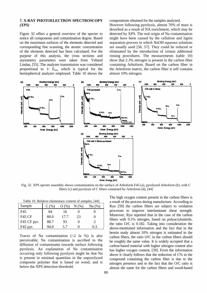
7. X-RAY PHOTOELECTRON SPECTROSCOPY
(XPS)
Figure 32 offers a general overview of the specter to
notice all components and contamination degree. Based
on the maximum surfaces of the elements detected and
corresponding fine scanning, the atomic concentration
of the elements detected has been calculated. For the
purpose of this analysis, the cross sections and
asymmetry parameters were taken from Yehand
Lindau, [55]. The analyzer transmission was considered
proportional to 1/ Ekin, which is typical for the
hemispherical analyzer employed. Table 10 shows the
compositions obtained for the samples analyzed.
However following pyrolysis, almost 70% of mass is
desorbed as a result of NA enrichment, which may be
detected by XPS. The real origin of Na contamination
might have been caused by the cellulose and lignin
separation process in which NaOH aqueous solutions
are usually used [56, 57]. They could be reduced or
eliminated by the introduction of certain additional
rinsing procedures. The measurements (table 10)
show that 2.3% nitrogen is present in the carbon fiber
containing Arboform. Based on the carbon fiber in
the Arboform matrix, the carbon fiber it self contains
almost 10% nitrogen.
Fig. 32. XPS specter assembly shows contamination on the surface of Arboform F45 (a), pyrolyzed Arboform (b), with C
fibers (c) and pyrolysis of C fibers contained by Arboform (d), [44]
Table 10. Relative elementary content of samples, [44]
Sample C (%) O (%) N (%) Na (%)
F45 84 16 0 0
F45 CF 80.0 17.7 23 0
F45 CF pyr. 88.7 93 0 2
F45 pyr. 94.0 5.7 0 0.3
Traces of Na contamination (<2 la %) is also
perceivable; Na contamination is ascribed to the
diffusion of contaminants towards surface following
pyrolysis. An explanation of Na contamination
occurring only following pyrolysis might be that Na
is present in minimal quantities in the unpyrolyzed
composite polymer that is based on wood, and is
below the XPS detection threshold.
The high oxygen content present in the carbon fibers is
a result of the process during manufacture. According to
Ryu [59] the carbon fibers are subject to oxidation
processes to improve interlaminate shear strength.
Moreover, Ryu reported that in the case of the carbon
fibers with 9.1% nitrogen, based on polyacrylonitrile,
the ratio O/C is 0.182. Taking into consideration the
above-mentioned information and the fact that in the
herein study almost 10% nitrogen is estimated in the
carbon fibers, the ratio O/C in the carbon fibers should
be roughly the same value. It is widely accepted that a
carbon-based material with higher nitrogen content also
has higher oxygen content, [59]. From the information
above it clearly follows that the reduction of C% in the
compound containing the carbon fiber is due to the
nitrogen presence and to the fact that the O/C ratio is
almost the same for the carbon fibers and wood-based

81
compound. After pyrolysis the carbon content is lower
than in the case of free Arboform with carbon fiber.
A cause may be the higher oxygen content of the raw
material. Moreover the greater value of Na (that reacts
to oxygen) contamination produces more oxygen in the
pyrolyzed carbon fibers containing Arboform (2% Na)
than in the free Arboform fibers (0.3% Na). Another
cause of the lower carbon content and higher oxygen
content following pyrolysis may be ascribed to the thick
matrix of the wood-based polymeric compound
containing carbon fibers. On the other hand, oxygen
cannot be released from the material at the same
temperature applied to the system containing
onlyArboform F45. Thus it is reasonable that, for the
realization of complete pyrolysis, the addition of carbon
fibers resulting in thick matrix requires higher
temperature. A fine C 1s (figure 33) has been carried
out to achieve a detailed analysis of the mandatory
sample relative correlations because the peak transition
of the functional groups is solvable between different
binding correlations, [12]. The peak C-O is moved by
1.4± 0.1 eV and C=O is moved by 3.1 ±0.1 eV at
greater binding energy to peak C-C/C-H, in line with the
specialty literature, [60, 61].
The binding energy of the lignin-cellulose compound
is directed in relation to the carbon fiber signal.
Following pyrolysis, the change of basic level energy
disappears, which indicates the fact that the fiber
compound dissolves in the compound matrix, [44].
Arboform is non-conducting material. As a result, the
photoelectrons migrate from the surface and change
the surface potential. According to this phenomenon
the analyzed basic levels are displaced. Arboform
that was not pyrolyzed with C fibers has low
conductivity in Arboform matrix and high
conductivity across the conducting fiber network. In
this event the peaks of the basic levels should be
separated in two parts: one representing the matrix
and the other component is assigned to the fiber
network. This phenomenon is well known in the
specialty literature and is called differential loading,
[62]. There are a few possibilities to eliminate this
phenomenon. One possibility consists in reducing the
layer thickness to make it as thin as possible; the
thickness reduction has been achieved on wood-based
polymers [63], but in this study was not possible.
Another possibility is the usage of the neutralizer
intended for cellulose [64] and lignin [65]
measurements. However, some reports point to the
fact that the differential loading may be used to obtain
further information on the analyzed material [66, 67].
The basic level satisfies the above presumption and
indicates the expected sample composition. Following
the pyrolysis at 1200 °C graphitization generates a
conducting material. In this case, the differentiation
between carbon fiber network and material matrix
submitted to pyrolysis is not possible.
Fig. 33. XPS fine scan of non-pyrolysis (a) and pyrolysis
(b) in the carbon fiber containing ArboformF45, [44]
8. FTIR ANALYSIS –FOURIER
TRANSFORM INFRARED
SPECTROSCOPY
To obtain specters, FTIR Thermo Scientific Nicolet ™
6700 has been used. Under full regime, the apparatus
attenuates total reflection (ATR-IR), has 4 cm-1
resolution and can achieve 32 scans per sample.
Figure 34 shows the FTIR specters of the pure PBS,
lignin and PBS composite with 50% lignin with and
without PMDI. The carbonyl feature (C = O) is present
from 1735 to 1750 cm-1, C-O stretches from 1145 to
1155 cm-1and C-H stretches from 2850 to 2950cm
-1 and
is evident in PBS specters and its composites. Large
hydrogen peaks bind the groups -OH at (3400-3100) cm-
1which occur in all lignin specters and composites. The
characteristic lignin peaks have been previously
discussed in the lignin chapter. It may also be observed
that all PBS and lignin characteristic peaks are present in
composites. The peak at 1370 cm-1in the lignin specter
(due to OH phenol group) moved to 1388 cm-1in the
composite specter which might have occurred as a result

82
of the interaction between lignin OH groups and PBS
matrix C = O groups. The NCO (isocyanate) non-
characteristic peak, group from 2270 cm-1, occurs in the
specters of the compatibilized composites that indicate a
complete reaction of the isocyanate in composite system.
Fig. 34.FTIR specters of lignin, PMDI and composites, [28]
Due to the special properties, Arboform has been
extensively used in many fields of activity. Thus this
material is used in the automotive industry to make
interior parts (fine veneers, panels, battery holder, precise
3D templates, strips, steering wheel) [6, 68, 69, 70], civil
engineering (flooring, slabs, hand railing, window frame
sections) [6, 71], electronics (spherical loudspeaker,
mobile case and cover, loudspeaker board, keyboard,
mouse) [6, 21,72, 73 ], commodities industries (knives,
glasses, plates, glass pads, films) [6, 74, 75]), precision
mechanics (watch cases, sporting riffle, technical parts)
[6, 18, 76], furniture industry (chairs, armchairs arms,
table legs) [6, 70], manufacture of musical instruments
(flute, harmonica) [73], jewelry (jewelry box, pendant,
beads) [2], toys (baby- pacifier, play board, nativity
figurine) [2], gardening products (garden furniture,
garden implements) [6], and other general interest
products (heels and shoe platform, stamps, vase, lamps,
ornamental spheres, hangers, eyeglasses frames, funerary
urns, small-sized coffins) [75].
9. CONCLUSIONS
"Liquid wood” is available in three different types
such as: ARBOFORM -
Liquid wood (based on
lignin, organic additives and natural fibers),
ARBOBLEND plastic composite with wood (its
content is based on biopolymers degree, e.g.: lignin,
starch, natural resins, wax and cellulose), ARBOFILL
biopolymeric composite (polymers and natural fibres-
based compound provided with natural cork aspect).
The Arboform has been developed by Fraunhofer
Institute for Chemical Technology together with
Tecnaro GmbH, Germany. Arboform is available in
three product variants according to the corresponding
quantities of mixed components: LV3 Nature,
F45Nature and LV5 Nature.
Take into account all the researches presented in this
article the Arboform is the material that will replace
plastic in the near future. Considering the results
presented, mechanical, thermal, chemical, electrical,
structural properties, the following plastic materials could
be replaced: PE (polyethylene), PVDF (Poly Vinylidene
Fluoride), PCTFE (Ethylene Copolymer) PA 12
(polyamide); PE-HD (High Density Polyethylene); ABS
(Acrylonitrile-butadiene-styrene); PVDF (Poly
Vinylidene Fluoride), ECTFE (Etylene Copolymer);
POM (Acetal Homopolymer) etc. Also it is important to
pint out that the Arboform can be reinforced with
different natural fibers leading to the injection process
improvement and increase of properties.
ACKNOWLEDGMENT
This work was supported by the strategic grant
POSDRU/159/1.5/S/133652, co-financed by the
European Social Fund within the Sectorial Operational
Program Human Resources Development 2007 – 2013.
10. REFERENCES
1.Srikanth Pilla, (2011), Engineering Applications of
Bioplastics and Biocomposites- An overview,
Handbook of Bioplastics and Biocomposites
Engineering Applications, Published John Wiley &
Sons, New Jersey,pp. 1-14.
2.Helmut Nagele, Jurgen Pfitzer, Lars Ziegler, Emilia
Regina Inone-Kauffmann, Wilhelm Eckl, and Norbert
Eisenreich, (2014), Lignin Matrix Composites from
Natural Resources - ARBOFORM®, Bio-Based
Plastics: Materials and Applications, First Edition.
Edited by Stephan Kabasci, John Wiley &Sons.Ltd.
Published 2014 by John Wiley & Sons, Ltd.
3.Laurichesse S, Av´erous L, (2013), Chemical
modification lignins: towards biobased polymers,
Progress in Polymer Science (2013),
http://dx.doi.org/10.1016/j. progpolymsci..11.004.
4.Patanjali Varanasi, Priyanka Singh, Manfred Auer,
Paul D Adams, Blake A SimmonsandSeema Singh,
(2013), Survey of renewable chemicals produced
from lignocellulosic biomass during ionic liquid
pretreatment,Biotechnology for Biofuels.
5.International Lignin Institute: http://www.ili-
lignin.com/aboutlignin.php Accessed at: 12.02.2014.
6.Official Arboform producer webpage:
http://www.tecnaro.de/english/grundsaetze.htm?secti
on=arboform Accessed at: 10.02.2014.
7.Jae-Young Kim, Eun-Jin Shin, In-Yong Eom,
Keehoon Won, Yong Hwan Kim , Donha Choi ,In-
Gyu Choi, JoonWeon Choi, (2011), Structural
features of lignin macromolecules extracted with
ionic liquid from poplar wood, Bioresource Technology
102, pp. 9020–9025.

83
8.Oldham, P.B., Wang, J., Conners, T.E. and Schultz, T.P. (1993) Rapid analysis of pulp lignin: a review of N1R and FTIR and preliminary investigation of multidimensional fluorescence spectroscopy. Pulping Conference, pp. 653. 9.Porter, J., Sands, T. and Trung, T. (2009) Understanding Kraft liquor cycle: a need for online measurement and control. TAPPI Engineering, Pulping and Environmental Conference October 11-14, Memphis Tennessee, pp. 1-12. 10.Becker W., Inone-Kauffmann E., Eckl W., Eisenreich N., (2007), Near infrared spectroscopy for inline control of biopolymer Processing. Proceedings of the Polymer Processing Society, Annual Meeting, PPS23, San Salvador, Brazil. 11.Rohe T., Becker W.,Krey A. et al. (1998), In-line monitoring of polymer extrusion processes by NIR spectroscopy, Journal of Near Infrared Spectroscopy, 6, 325-332. 12.Martens, H. and Naes, T., (1989), Multivariate Calibration, John Wiley & Sons, Ltd, Chichester. 13.Jedicke, O.Eisenreich, N. and Diimpert, H., (2000), Aquasolv® - Hydrothermolyse -The Development of a Process for Completely Use of Biomass, Proceedings 1st Biomass World Conference, Sevilla, Spain. 14.Practical research of wood-like thermoplastic using lignin extracted by high pressure hydrolysis process, (Patent registration number 2002GP008). 15.Mohanty, A. K., Misra, M. and Drzal, L. T., (2002), Sustainable Bio-Composites from Renewable Resources: Opportunities and Challenges in the Green Materials World, Journal of Polymers and the Environment, 10(1/2). 16.Naegele H., Pfitzer J., Naegele E., Inone ER., Eisenreich N., Eckl W., et al. (2002), ARBOFORM – a thermoplastic, processable material from lignin and natural fibers. In: Hu TQ, editor. Chemical modification, properties, and usage of lignin, New York, Kluwer Academic/Plenum. 17.Dumitru Nedelcu, Ciprian Ciofu, Nicoleta Monica Lohan, (2013), Microindentation and differential scanning calorimetry of ‘‘liquid wood’’, Composites: Part B 55, pp. 11–15. 19.Ellis, Meagan, (2009), Toy turn for bioplastics, Materials World, 17(2), ProQuestCentral, pp. 20. 20.Mark Johnson, (2004), Commercially Available Low Environmental Impact Polymers, Low Environmental Impact Polymers: Overview. 21.Nägele, H., Pfitzer, J., Lehnberge,r C., Landeck, H., (2005), Renewable resources for use in printed circuit boards, Circuit World; 31, 2, ProQuest Central, pp. 26. 22.”How Arboform Works” How Stuff Works. [Online: Blog]. Available: http://blogs.howstuffworks.com/ 2010/07/19/how-arboform-works-a-plastic-made-of-lignin-from-wood-that-biodegrades-like-wood/, (2011). 23.Björn Winberg, KAM Industries, (2010), Albis
Plastic Scandinavia AB, Commercial biopolymers Properties and limitations. 24.”Liquid Wood: A New Plastic That Grows on Trees” Discover Magazine. [Online: Article]. Available: http://blogs.discovermagazine.com/ discoblog/2008/12/04/liquid-wood-a-new-plastic-that-grows-on-trees/, (2011). 25.”A Greener Alternative to Plastics: Liquid Wood” MSNBC. [Online; Article]. Available. http://www.msnbc. msn.com/id/28283260/ns/technology_ and_science-innovation/t/greener-alternative-plastics-liquid-wood/#.Tq9R3VZkedx, (2008). 26.A batter world “liquid wood”: Eco-friendly alternative to synthetic plastics. Available. http://www.youthxchange.net/main/ai136_liquid-wood.asp, Accessed at 12.03.2014. 27.Jürgen Pfitzer, Helmut Nägele, (2011), Trends beiBiokunststoffen – Anwendungsbeispiele und Neuentwicklungen, Tecnaro GmbH. 28.Saswata Sahoo, Manjusri Misra, Amar K. Mohanty, (2011), Enhanced properties of lignin-based biodegradable polymer composites using injection moulding process, Composites: Part A 42: 1710–1718. 29.Toriz G, Denes F, Young RA, (2002), Lignin-polypropylene composites. Part1: composites from unmodified lignin and polypropylene. Polym Compos; 23: pp. 806–13. 30.Nyambo C, Mohanty AK, Misra M., (2010), Polylactide-based renewable greencomposites from agricultural residues and their hybrids, Biomacromolecules; 11: pp. 1654–60. 31.Kim HS, Yang HS, Kim HJ., (2005), Biodegradability and mechanical properties of agroflour–filled polybutylene succinate biocomposites, J Appl Polym Sci; 97:1513–21. 32.Jiang L, Chen F, Qian J, Huang J, Wolcott M, Liu L, et al. (2010), Reinforcing andtoughening effects of bamboo pulp fibre on poly (3-hydroxybutyrate-co-3-hydroxyvalerate) fibre composites, Ind Eng Chem Res; 49:572–7. 33.Ciemniecki SL, Glasser WG. (1989), Polymer blends with hydroxypropyl lignin. In: Glasser WG, Sarkanen S, editors. Lignin properties and material. Washington (DC): American Chemical Society. 34.Chen F, Liu L, Cooke PH, Hicks KB, Zhang J. (2008), Performance enhancement of poly (lactic acid) and sugar beet pulp composites by improving interfacial adhesionand penetration. Ind Eng Chem Res; 47:8667–75. 35.Madden JP, Baker GK, Smith CH. (1971), Study of polyether-polyol- and polyesterpolyol-based rigid urethane foam systems. In: Technical report made for United States department of energy and paper submitted to 162nd national meeting. Washington, DC: American Chemical Society, September. 36.Shih YF, Lee WC, Jeng RJ, Huang CM, (2006), Water bamboo husk-reinforcedpoly (butylene succinate) bio-degradable composites. J Appl Polym Sci; 99:188–99.

84
37.Scholz G, Lohr J, Windeisen E, Tröger F, Wegener G. (2009), Carbonization of hotpressedArboform-mixtures. Eur J Wood Wood Prod; 67:351–5. 38.Lee SM, Cho D, Park WH, Lee SG, Han SO, Drzal LT. (2005), Novel silk/poly (butylene succinate) biocomposites: the effect of short fibre content on their mechanical and thermal properties. Compos Sci Technol; 65:647–574. 39.Lee B-H, Kim H-S, Lee S, Kim H-J, Dorgan JR, (2009), Bio-composites of kenaf fibers inpolylactide: role of improved interfacial adhesion in the carding process.Compos Sci Technol;69:2573–9. 40.Singh S, Mohanty AK, Sugie T, Takai Y, Hamada H. (2008), Renewable resource basedbiocomposites from natural fiber and polyhydroxybutyrate-co-valerate (PHBV) bioplastic. Composites: Part A, 39,:875–86. 41.Jordan, J. Jacob, K.I., Tannenbaum, R. et al. (2005), Experimental trends in polymer nanocomposites - a review. Materials Science and Engineering A, 393, 1-11. 42.Droval, G., Feller, J.F., Salagnac, P. and Glouannec, P. (2008), Conductive polymer composites with double percolated architecture of carbon nanoparlicles and ceramic microparticles for high heat dissipation and sharp PTC switching, Smart Materials and Structures, 17 (2), 1-10. 43.Devi G., Rao V.J., (2000), Room temperature synthesis of colloidal platinum nanoparticles, Bulletin of Materials Science, 23, 467-470. 44.Thomas Haensel, Andreas Comouth, Nicolas Zydziak, Eva Bosch, Axel Kauffmann, Juergen Pfitzer, Stefan Krischok, Juergen A. Schaefer, Syed Imad-Uddin Ahmeda, (2010), Pyrolysis of wood-based polymer compounds, Journal of Analytical and Applied Pyrolysis, 87, pp.124–128. 45.M. Filippi, L. Calliari, (2006), Surf. Interf. Anal., 38, pp. 595. 46.E. Camps, L. Escobar-Alarco´n, M.E. Espinoza, M.A. Camacho-Lo´ pez, S.E. Rodil, S.Muhl, (2003), Superficies Vacio, 16, pp. 37. 47.Kauffmann, A., Eisenreich, N., Weiser, V., (2005), LeitfahigesFormteil, Verfahrenzu seiner Herstel-lung und Verwendungdesselben, DE 103 47 701 Al. 48.Hadjiev, H., Frey, H., Khan. H.R. (2011), Decompositon and oxidation of cyclopentasilane diluted in toluene. Proceeding of 42nd International Annual Conference of Fraunhofer ICT, Karlsruhe, Germany. June-01 July, p. 103. 49.Hadjiev, H., Khan, H.R., Frey, H. et al. (2012) Decomposition and oxidation of cyclopentasilane. Proceeding of 43rd International Annual Conference, of the Fraunhofer ICT, Karlsruhe, Germany, 26 June - June. 50.H. Naegele, J. Pfitzer, C. Lehnberger, H. Landeck, K. Birkner, U. Viebahn, W. Scheel,R. Schmidt, M. Hagenlken, J. Mller, (2005), Circuit World, 31, pp.26. 51.http://www.tohotenax-eu.com/. Accessed at 12.11.2013. 52.R. Taipalus, T. Harmia, M.Q. Zhang, K. Friedrich, (2001), Compos. Sci. Technol. 61 801.
53.G. Cherkashinin, S. Krischok, M. Himmerlich, O. Ambacher, J.A. Schaefer, (2006), J. Phys.Condens. Matter 18, 9841. 54.Weihua K, He Y, Asakawa N, Inoue Y. (2004) ,Effect of lignin particles as a nucleating agent on crystallization poly (3-hydroxybutyrate). J Appl Polym Sci; 94: 2466–74. 55.J.J. Yeh, I. Lindau, At. Data Nucl. Data Table 32 (1985) 1. 56.A. Isogai, R.H. Atalla, Cellulose 5 (1998) 309. 57.H.M. Wang, R. Postle, R.W. Kessler, W. Kessler, (2003), Text. Res. J., 73, 664. 58.S.-K. Ryu, B.-J. Park, S.-J. Park, (1999), J. Colloid Interf. Sci., 215, 167. 59.E. Pollak, G. Salitra, A. Soffer, D. Aurbach, (2006), Carbon, 44, 3302. 60.G. Beamson, D. Briggs, (1998), The XPS of Polymers Database, Surface Spectra, Manchester,. 61.L.M. Matuana, J.J. Balatinecz, R.N.S. Sodhi, C.B. Park, (2001), Wood Sci. Technol., 35, 191. 62.R.H. Bradley, I.L. Clackson, D.E. Sykes, (1994), Surf. Interf. Anal., 22, 497. 63.L. Klarho¨ fer, B. Roos, W. Vio¨ l, O. Ho¨ fft, S. Dieckhoff, V. Kempter, W. Maus-Friedrichs, Holzforschung 62 (2008), 688. 64.L.-S. Johansson, Mikrochim. Acta 138 (2002) 217. 65.T. Haensel, A. Comouth, P. Lorenz, S.I.-U. Ahmed, S. Krischok, N. Zydziak, A.Kauffmann, J.A. Schaefer, (2009), Appl. Surf. Sci. 255, 8183. 66.F. Karadas, G. Ertas, S. Suzer, (2004), J. Phys. Chem. B 108, 1515. 67.M. Dubey, I. Gouzman, S.L. Bernasek, J. Schwartz, Langmuir 22 (2006) 4649. 68.http://land-der-erfinder.de/?tag=arboform, Accessed at: 16.03.2014. 69.http://www.gruene-wunstorf.com/themen /allgemein-von-a-z/abfallwirtschaft/agrarwende/ bildung-allgemein/b%C3%BCrgerbeteiligung/city-bike/fracking/fukushima-mahnt/gigaliner/mox/ plastik-aus-holz/, Accessed at: 16.03.2014 70.http://www.greendiary.com/liquid-wood.html, Accessed at: 15.02.2014. 71.http://www.besedki.ck.ua/news/uchenye_izobreli_zhidkuju_drevesinu/2012-11-18-11, Accessed at: 12.03.2014. 72.http://norskmand.com/portfolio/liquid-wood-iphone-5-flap-case/, Accessed at: 16.03.2014. 73.http://www.plasticstoday.com/mpw/articles/fujitsu-launches-injection-molded-bioplastic-keyboard, Accessed at: 10.03.2014. 74.http://www.behance.net/gallery/Starbucks-Arboform-Cup/14089743, Accessed at: 16.03.2014. 75.http://aesop-innovation.com/pages/liquidwood-news.php, Accessed at: 15.03.2014. 76.http://www.designinsite.dk/htmsider/k0076.htm, Accessed at: 16.03.2014.
Received: April 15, 2014 / Accepted: December 10, 2014 /
Paper available online: December 15, 2014 © International
Journal of Modern Manufacturing Technologies.