Bio-Medical Instrumentation EC09 L25 Module 1 Jinesh K J Asst.Professor Dept. of ECE Jyothi...
108
Bio-Medical Instrumentation EC09 L25 Module 1 Jinesh K J Asst.Professor Dept. of ECE Jyothi Engineering College,Thrissur http://www.ece4u.in
-
Upload
meghan-stewart -
Category
Documents
-
view
219 -
download
0
Transcript of Bio-Medical Instrumentation EC09 L25 Module 1 Jinesh K J Asst.Professor Dept. of ECE Jyothi...
Bio-Medical InstrumentationEC09 L25
Module 1
Jinesh K J
Asst.Professor
Dept. of ECE
Jyothi Engineering College,Thrissur
http://www.ece4u.in
Topics
• Electrical activity of excitable cells – • functional organization of the peripheral nervous system –• electrocardiogram (in detail with all lead systems) -
electroencephalogram – • electromyogram – • electroneurogram- • electrode –electrolyte interface• polarisation-• polarisable and non polarisable electrodes- • surface electrodes –needle electrodes-micro electrodes-• practical hints for using electrodes- • ‘skin- electrodes’ equivalent circuit-• characteristics of ‘bio-amplifiers’

Basics of Biomedical Instrumentation System
Patient Transducers /Electrode
InstrumentationAmplifiers
Signal Processing
DisplayDevices
Printer
Computer
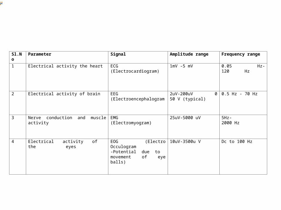
Sl.No Parameter Signal Amplitude range Frequency range
1 Electrical activity the heart ECG (Electrocardiogram) 1mV -5 mV 0.05 Hz-120 Hz
2 Electrical activity of brain EEG (Electroencephalogram
2uV-200uV 050 V (typical)
0.5 Hz - 70 Hz
3 Nerve conduction and muscle activity EMG(Electromyogram)
25uV-5000 uV 5Hz-2000 Hz
4 Electrical activity of the eyes
EOG (Electro Occulogram-Potential due to movement of eye balls)
10uV-3500u V Dc to 100 Hz

Electrical Activity of Excitable Cells
• Excitable cells – Exist in nervous, muscular and glandular tissue– Exhibit a resting potential and an action potential– Necessary for information transfer (e.g. sensory
info in nervous system or coordination of blood pumping in the heart)
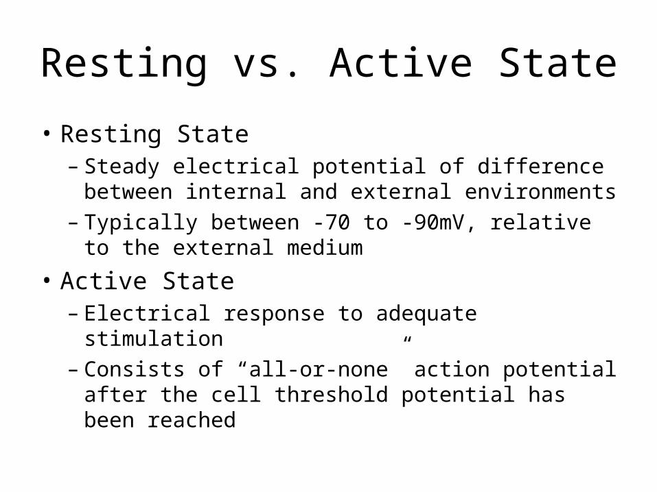
Resting vs. Active State
• Resting State– Steady electrical potential of difference
between internal and external environments– Typically between -70 to -90mV, relative to
the external medium
• Active State– Electrical response to adequate stimulation– Consists of “all-or-none” action potential after
the cell threshold potential has been reached
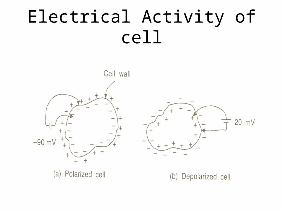
Electrical Activity of cell
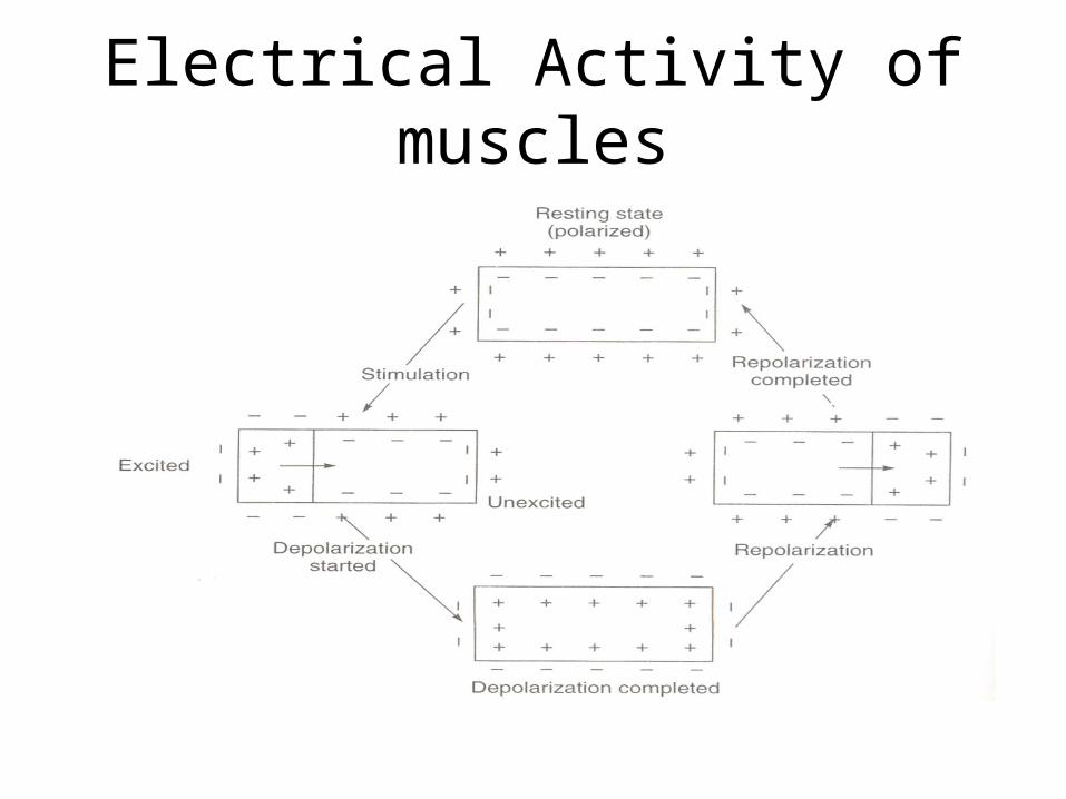
Electrical Activity of muscles

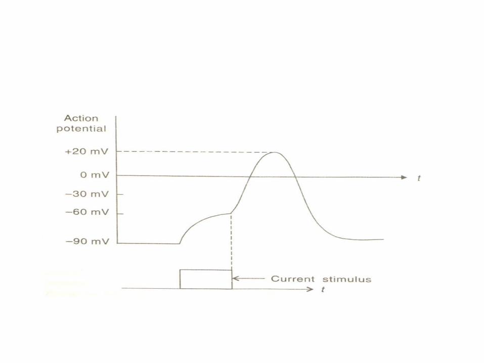
Recording of Action Potential

Resting Membrane Potential
• Cell potential is a function of membrane permeability and concentration gradient to various molecules (i.e. K+, Na+, Cl-, and Ca2+)
• Equilibrium potential is the membrane potential at which a given molecule has no net movement across the membrane– Nernst Equation (in Volts at 37 oC):
– n is the valence of K+, [K]i and [K]o are the intra- and extracellular concentrations, R is the universal gas constant, T is the absolute temperature in Kelvin, F is the Faraday constant, and EK is the equilibrium potential
i
o
i
oK K
K
K
K
nF
RTE
][
][log0615.0
][
][ln 10

Resting Membrane Potential
• Equilibrium membrane resting potential when net current through the membrane is zero
– P is the permeability coefficient of the given ion
• Factors influencing ion flow across the membrane– Diffusion gradients– Inwardly-directed electric field– Membrane structure– Active transport of ions against electrochemical
gradient
oCliNaiK
iCloNaoK
ClPNaPKP
ClPNaPKP
F
RTE
][][][
][][][ln
all-or-none law
• The all-or-none law is the principle that the strength by which a nerve or muscle fiber responds to a stimulus is independent of the strength of the stimulus. If the stimulus exceeds the threshold potential, the nerve or muscle fiber will give a complete response; otherwise, there is no response.

Action Potential
• Stimulation of excitable cells causes “all-or-none” response
• At threshold, the membrane potential rapidly depolarizes due to a change in membrane permeability– PNa significantly increases causing the membrane
potential to approach ENa (+60mV)
• A delayed increase in PK causes hyperpolarization and a return to resting potential

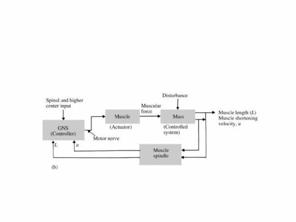
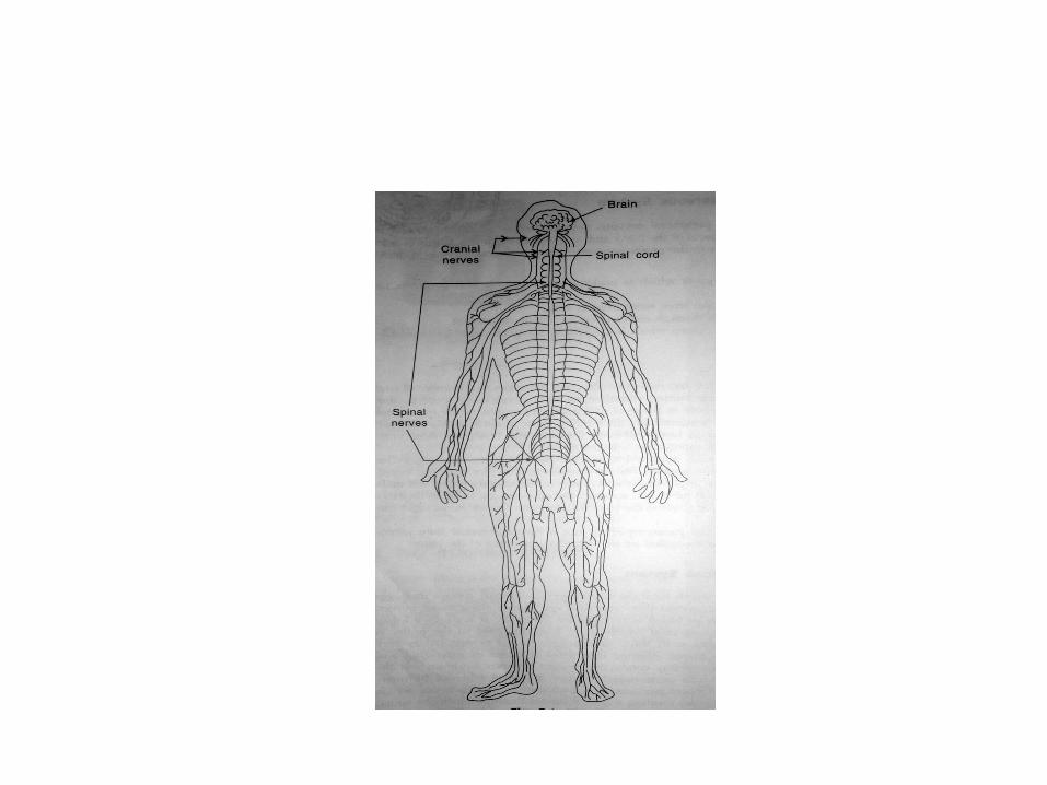
Organization of Peripheral Nervous System
• Reflex arc– Sense organ (e.g. receptors)– Sensory nerve (transfers information from receptor to
CNS)– CNS (i.e. information processing station)– Motor nerve (transfers information from CNS to
effector organ)– Effector Organ (i.e. muscles)
• Simplest example– Knee reflex
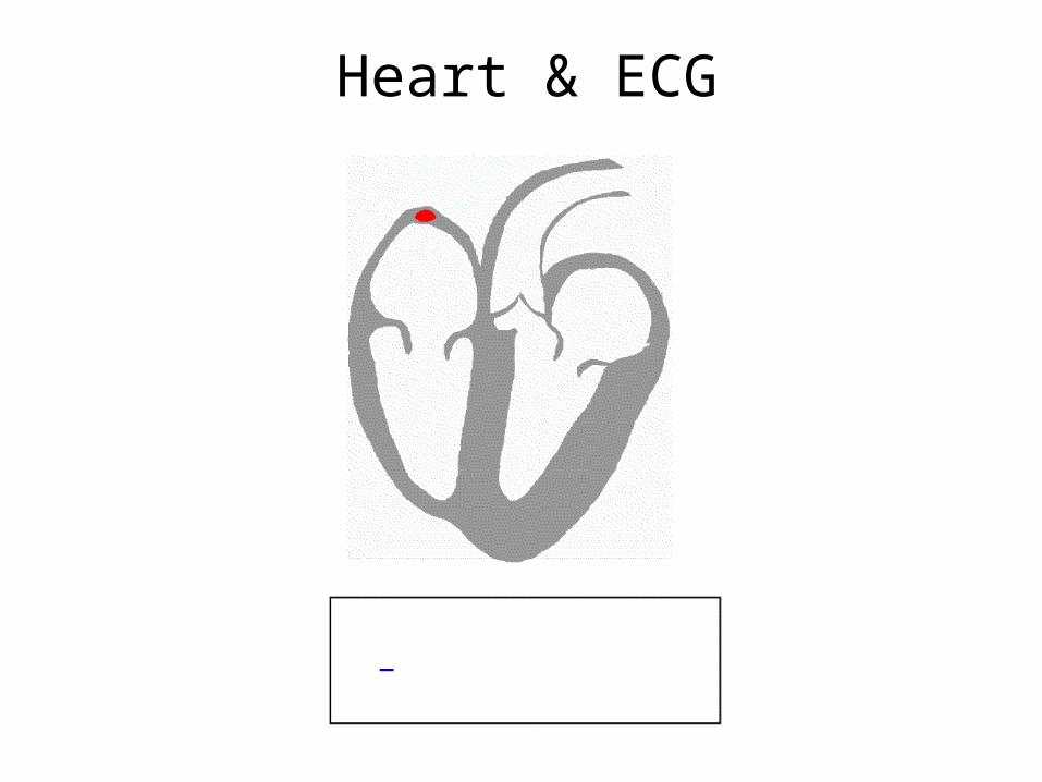
Heart & ECG
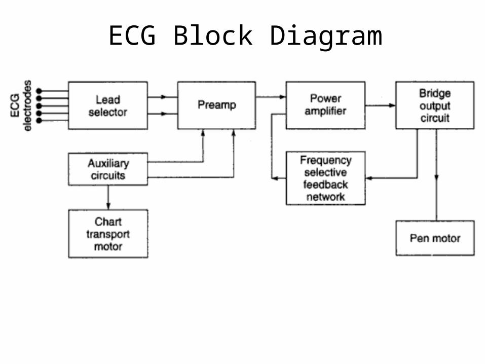
ECG Block Diagram
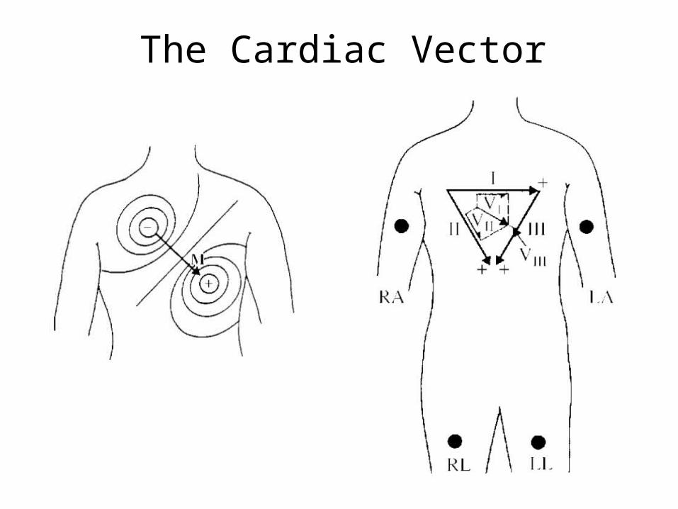
The Cardiac Vector
The vector sum of the frontal plane Cardiac Vector at any instant onto the three axes of the Einthoven Triangle will be zero.
•Lead 1: Potential between the Right Arm (RA) and the Left Arm (LA)•Lead 2: Potential between the Right Arm and the Left Leg •Lead 3: Potential between the Left Arm and the Left Leg
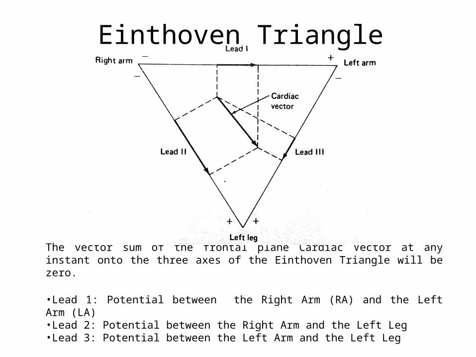
Einthoven Triangle
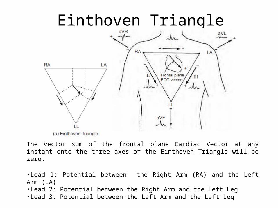
Einthoven Triangle
The vector sum of the frontal plane Cardiac Vector at any instant onto the three axes of the Einthoven Triangle will be zero.
•Lead 1: Potential between the Right Arm (RA) and the Left Arm (LA)•Lead 2: Potential between the Right Arm and the Left Leg •Lead 3: Potential between the Left Arm and the Left Leg
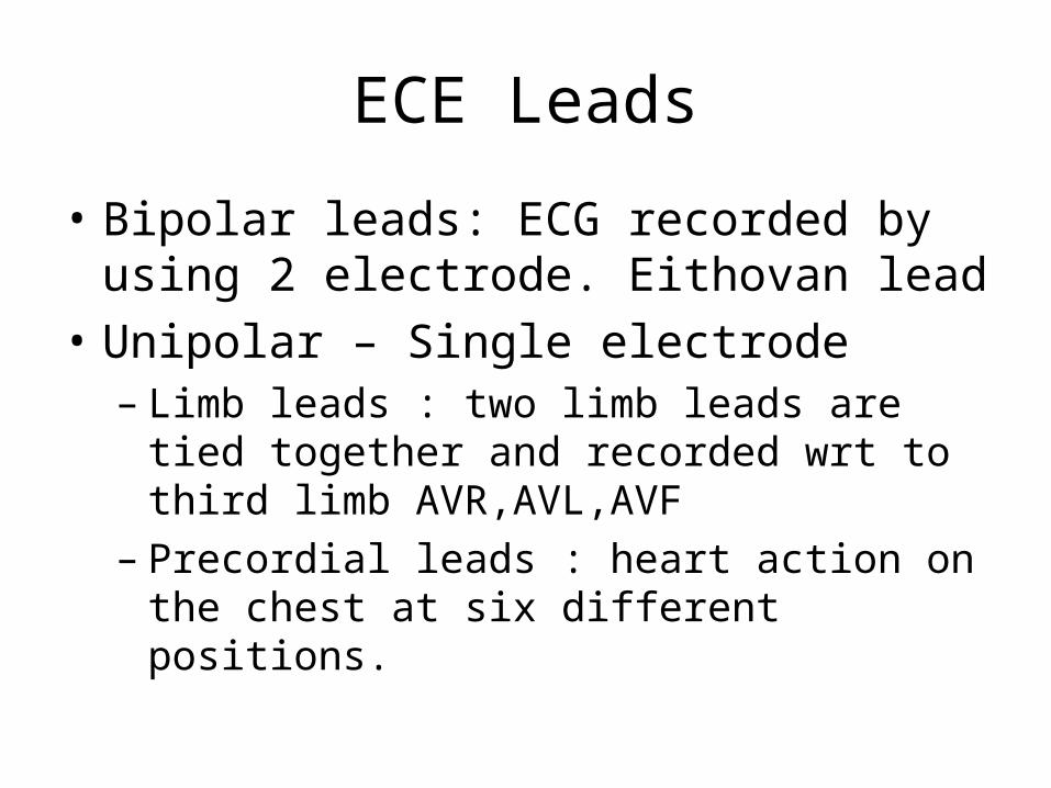
ECE Leads
• Bipolar leads: ECG recorded by using 2 electrode. Eithovan lead
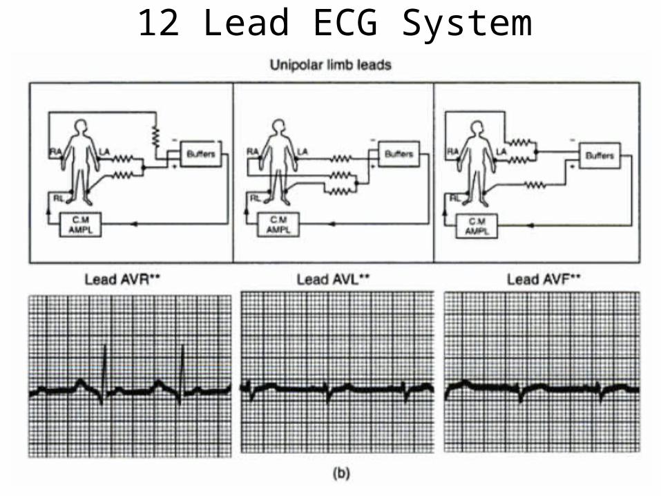
• Unipolar – Single electrode– Limb leads : two limb leads are tied together
and recorded wrt to third limb AVR,AVL,AVF– Precordial leads : heart action on the chest at
six different positions.
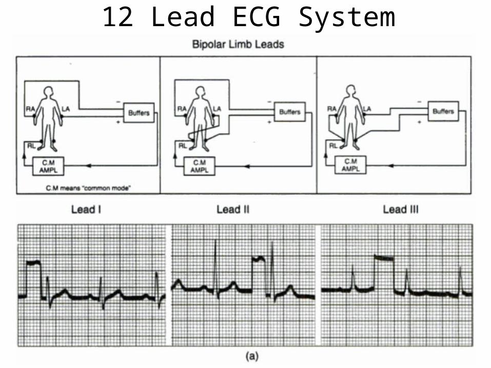
12 Lead ECG System

12 Lead ECG System
12 Lead ECG System
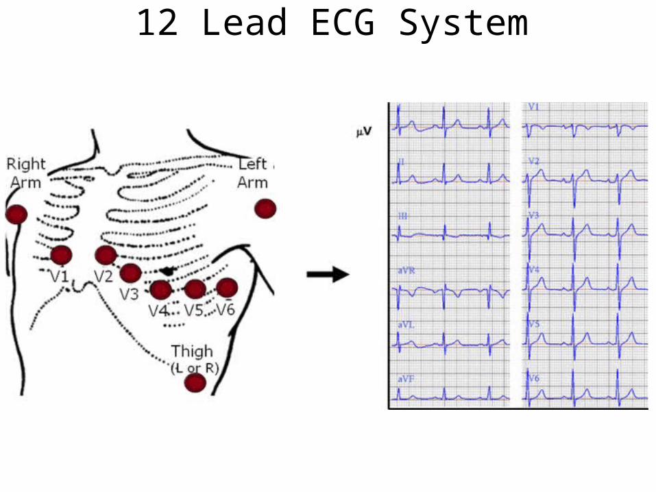
12 Lead ECG System
ECG
• The electric potentials generated by the heart appear throughout the body and on its surface.
• The potential difference is determined by placing electrodes on the surface of the body and measuring the voltage between them.
• A lead vector is a unit vector that defines the direction a constant-magnitude cardiac vector must have to generate maximal voltage in the particular pair of electrodes.
• A pair of electrodes, or combination of several electrodes through a resistive network that gives an equivalent pair, is refered to as a lead
• More than one lead must be recorded to describe the heart’s electric activity completely.
• In practice several leads are taken in the frontal plane and the transverse plane
ECG…• The three bipolar limb lead selections was first introduced by Einthoven.
• Einthoven postulated that at any instant of the cardiac cycle, the frontal plane representation of the electrical axis of the heart is a 2-D vector.
• The ECG measured from any one of the three basic limb lead is a time-variant 1-D component of that vector.
• Einthoven also made the assumption that the heart is near the center of an equilateral triangle, the apexes of which are the right and left shoulders and the crotch.
• ECG potentials at the shoulders are essentially the same as the wrists and that the potentials at the crotch differ little from those at either ankle.
• The points of this triangle represents the electrode positions of the three limb leads.
• This triangle is called Einthoven Triangle
ECG…
• The components of a particular cardiac vector can be determined easily by placing the vector within the triangle and determining its projection along each side.
• Three additional leads in the frontal plane as well as group of leads in the transverse plane are routinely used in taking clinical ECG.
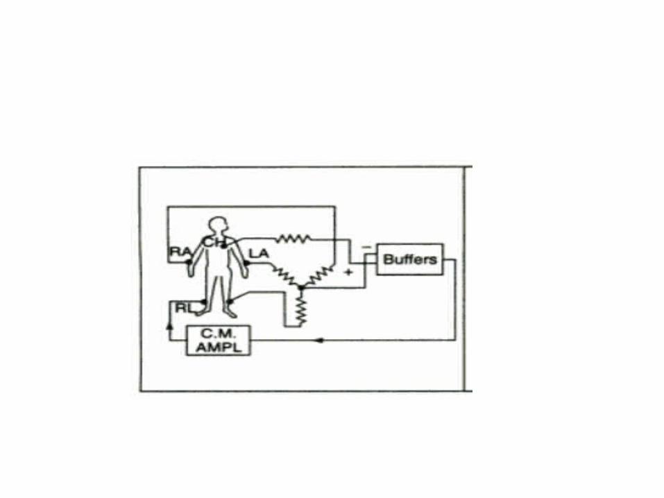
• These leads are based on signals obtained from more than one pair of electrodes referred to as unipolar leads
• Unipolar leads consists of potential appearing on one electrode taken with respect to an equivalent reference electrode, which is the average of the signals seen at two or more electrodes.
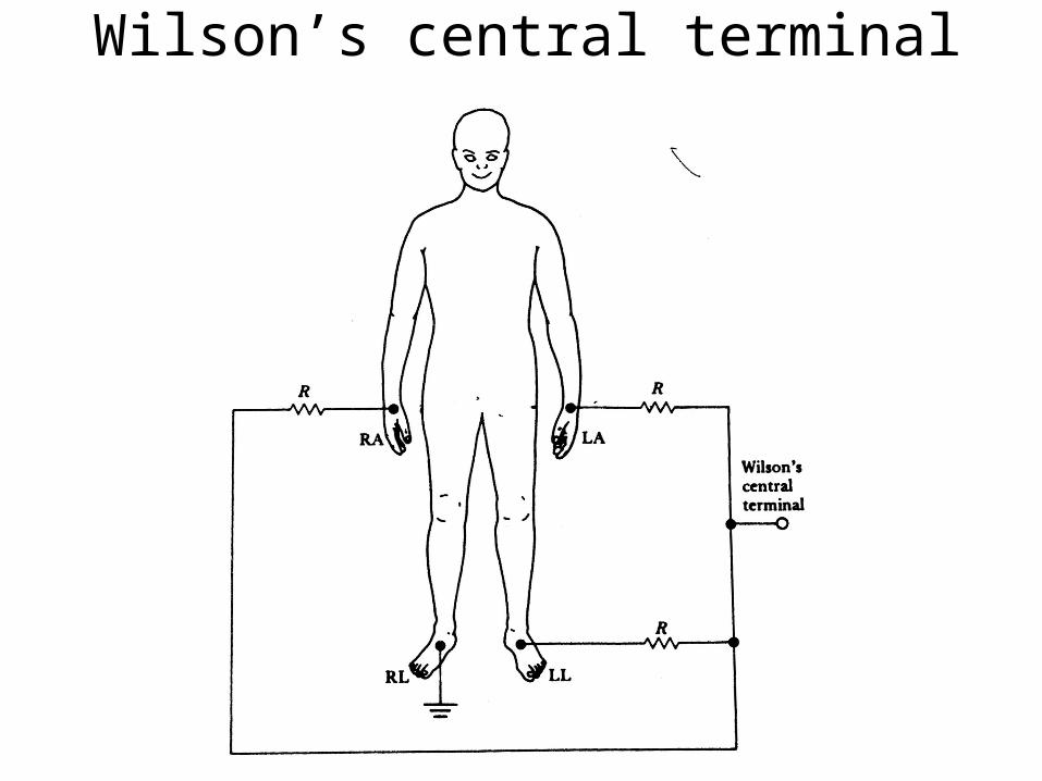
Wilson’s central terminal
Effects of artefacts
• Interference from power line
• Shifting of base line : – Wandering base line– Due to movement of patient electrode– Eliminated by ensuring that patient lies
relaxed and electrodes are properly attached.
• Muscle tremor
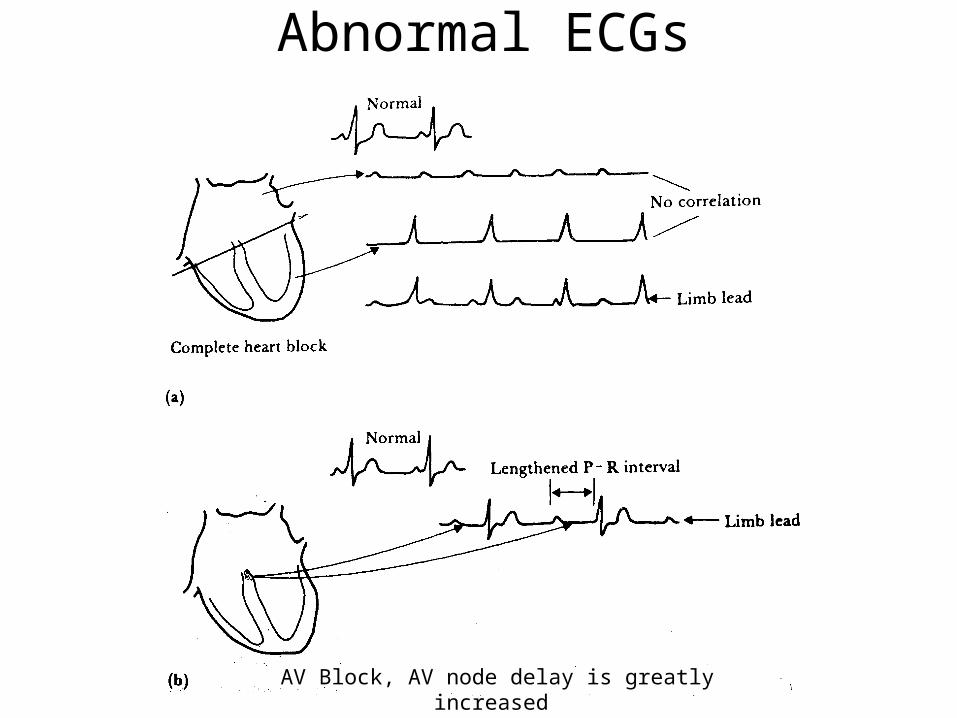
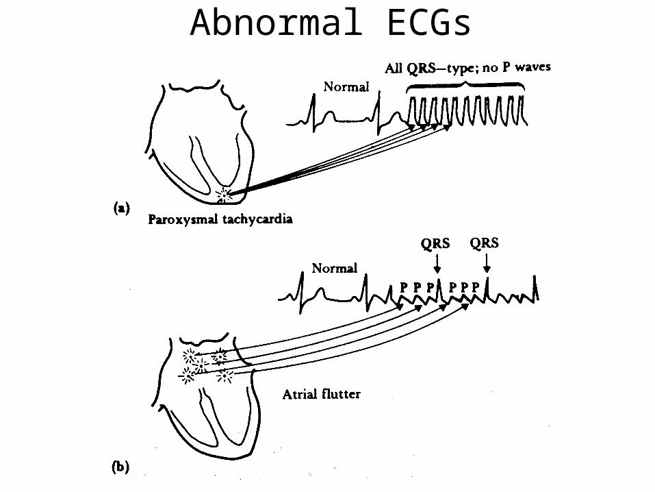
Abnormal ECGs
AV Block, AV node delay is greatly increased
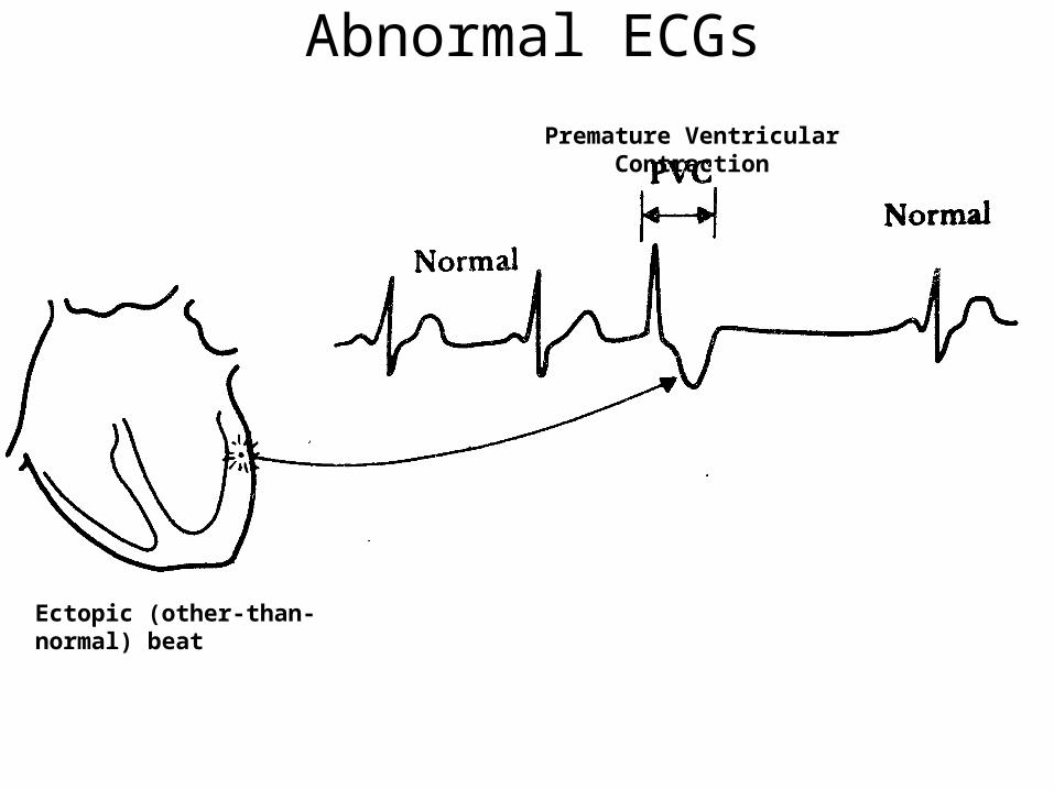
Abnormal ECGs
Ectopic (other-than-normal) beat
Premature Ventricular Contraction
Abnormal ECGs
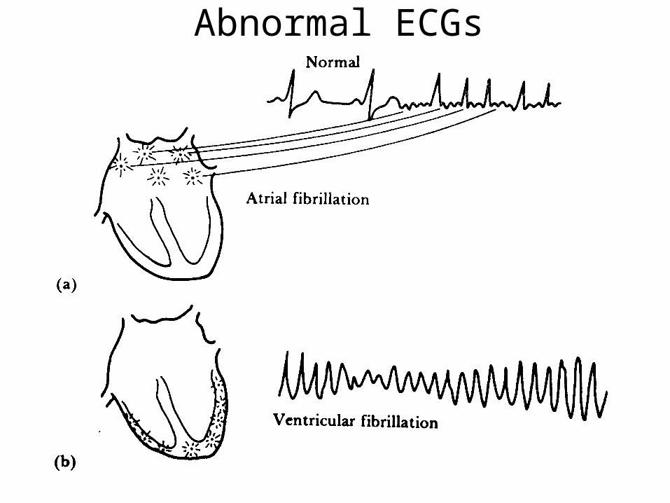
Abnormal ECGs
Electroencephalogram (EEG)• The background electrical activity of the brain was first analyzed in a systematic
manner by the German psychiatrist Hans Berger, who introduced the term electroencephalogram (EEG) to denote the potential fluctuations recorded from the brain.
• The recorded representation of bioelectric potentials generated by the neuronal activity of the brain is called the electroencephalogram (EEG).
• EEG potentials measured at the surface of the scalp, actually represent the combined effect of potentials from a fairly wide region of the cerebral cortex and from various points beneath.
• Experiments have shown that the frequency of the EEG seems to be affected by the mental activity of a person.
• The frequencies of these brain waves range from 0.5 to 100Hz, and their character is highly dependent on the degree of activity of the cerebral cortex.
• Some of these are characteristics of specific abnormalities of the brain, such as epilepsy.

The cerebral cortex
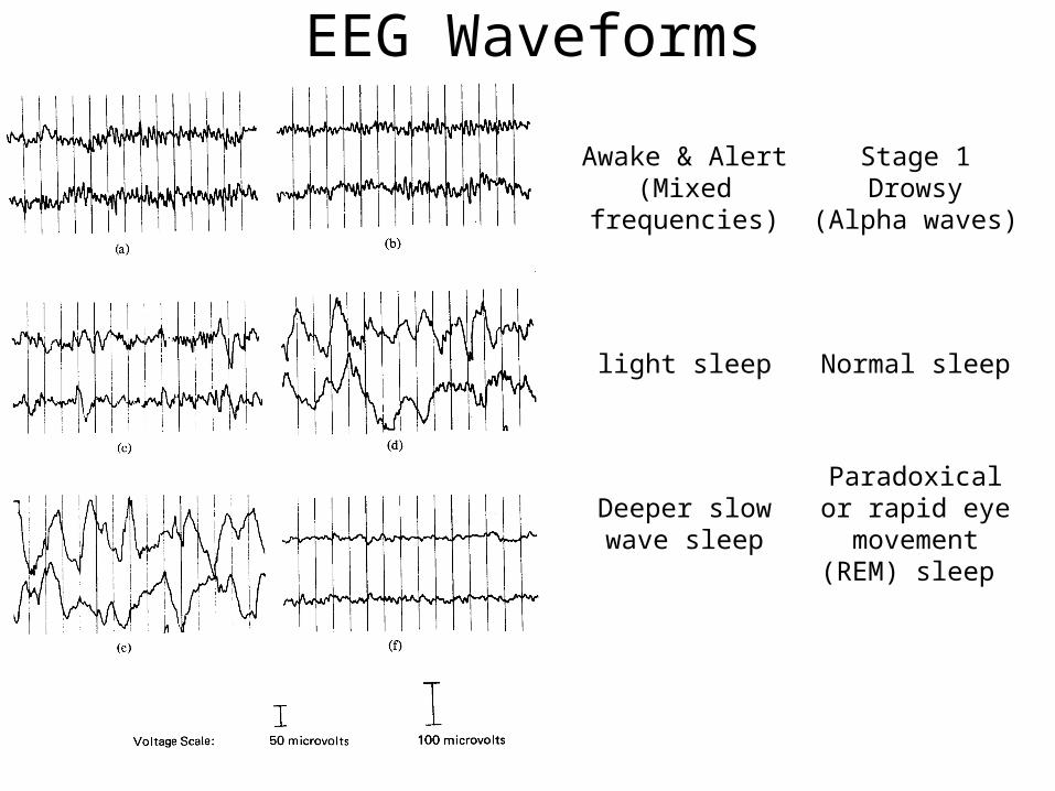
EEG Waveforms
Awake & Alert(Mixed
frequencies)
Stage 1Drowsy
(Alpha waves)
light sleep Normal sleep
Deeper slow wave sleep
Paradoxical or rapid eye
movement (REM) sleep
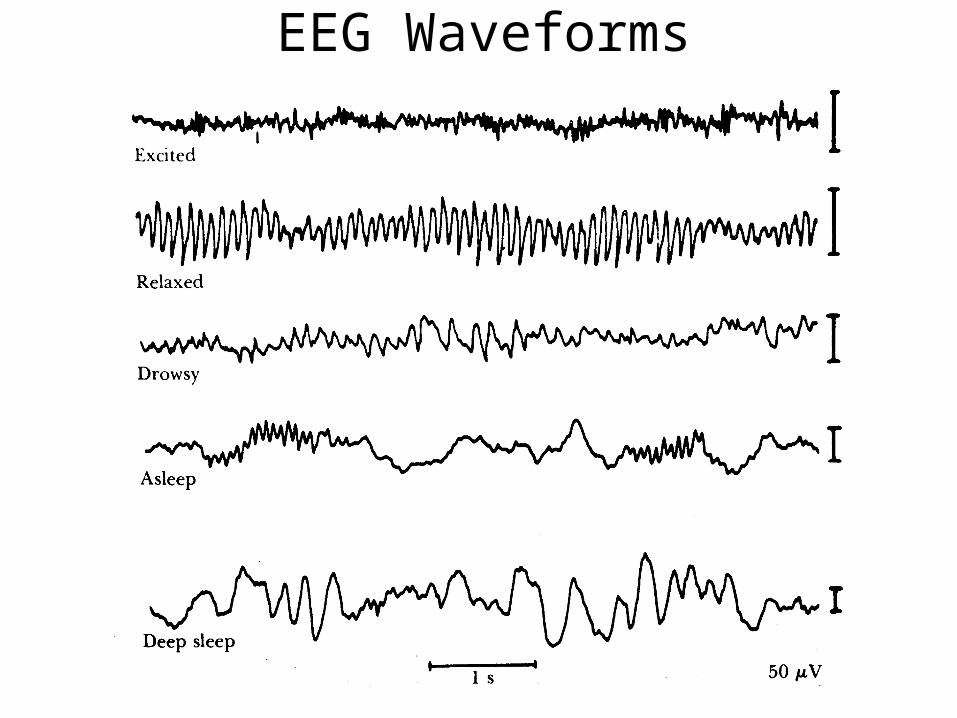
EEG Waveforms
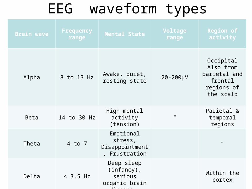
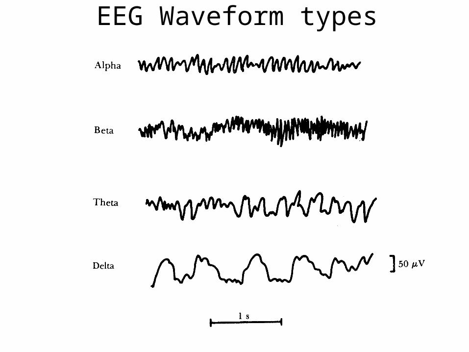
EEG waveform types
Brain waveFrequency
rangeMental State Voltage range
Region of activity
Alpha 8 to 13 HzAwake, quiet, resting state
20-200µV
OccipitalAlso from
parietal and frontal regions of
the scalp
Beta 14 to 30 HzHigh mental
activity (tension)“
Parietal & temporal regions
Theta 4 to 7Emotional stress, Disappointment,
Frustration“
Delta < 3.5 Hz
Deep sleep (infancy), serious
organic brain disease,
Within the cortex
EEG Waveform types
EEG waveform types
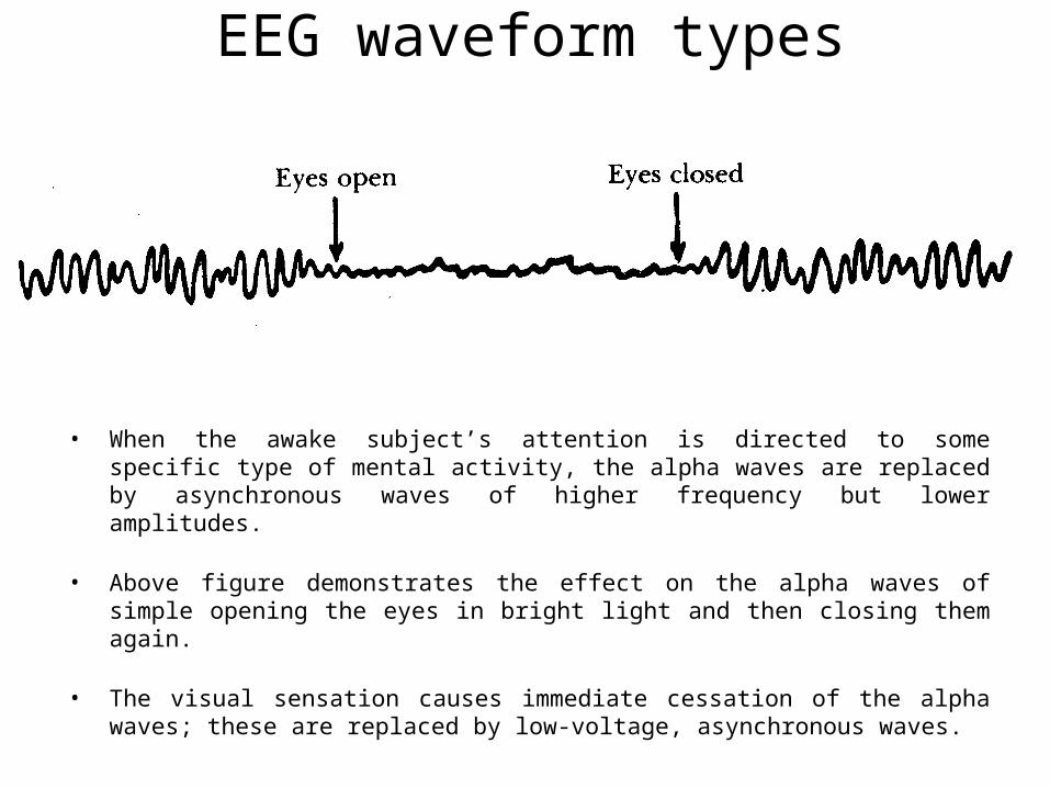
• When the awake subject’s attention is directed to some specific type of mental activity, the alpha waves are replaced by asynchronous waves of higher frequency but lower amplitudes.
• Above figure demonstrates the effect on the alpha waves of simple opening the eyes in bright light and then closing them again.
• The visual sensation causes immediate cessation of the alpha waves; these are replaced by low-voltage, asynchronous waves.
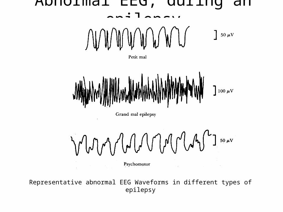
Abnormal EEG, during an epilepsy
Representative abnormal EEG Waveforms in different types of epilepsy
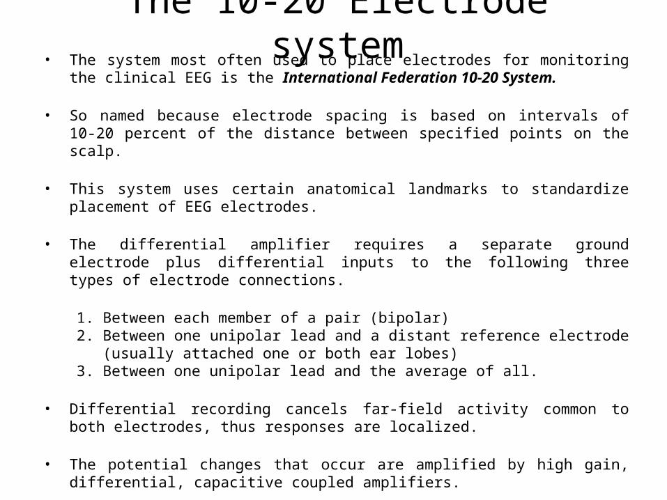
The 10-20 Electrode system• The system most often used to place electrodes for monitoring the clinical EEG is the
International Federation 10-20 System.
• So named because electrode spacing is based on intervals of 10-20 percent of the distance between specified points on the scalp.
• This system uses certain anatomical landmarks to standardize placement of EEG electrodes.
• The differential amplifier requires a separate ground electrode plus differential inputs to the following three types of electrode connections.
1. Between each member of a pair (bipolar)2. Between one unipolar lead and a distant reference electrode (usually attached
one or both ear lobes)3. Between one unipolar lead and the average of all.
• Differential recording cancels far-field activity common to both electrodes, thus responses are localized.
• The potential changes that occur are amplified by high gain, differential, capacitive coupled amplifiers.
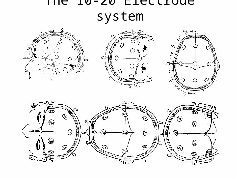
The 10-20 Electrode system
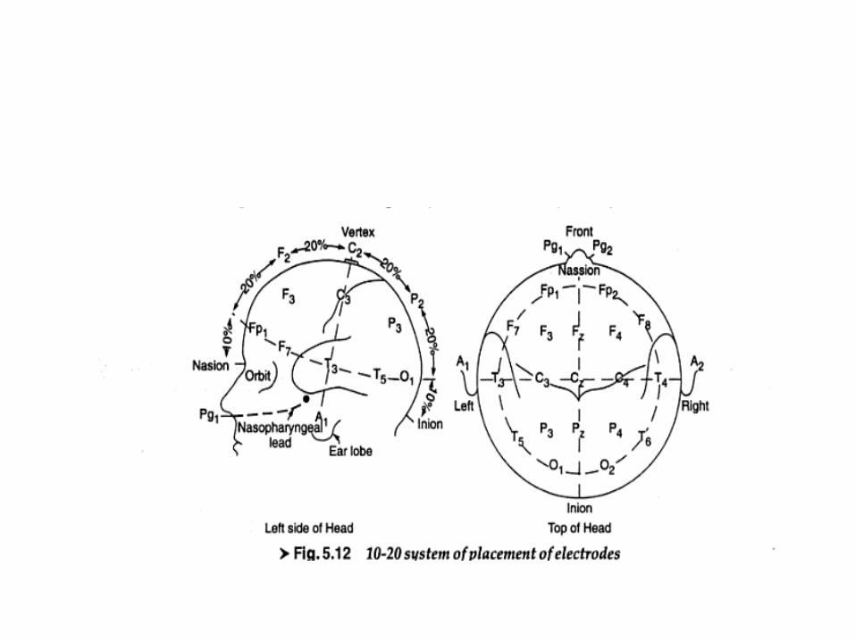
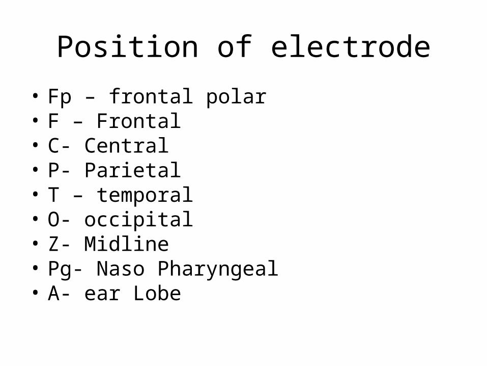
Position of electrode
• Fp – frontal polar• F – Frontal• C- Central• P- Parietal• T – temporal• O- occipital• Z- Midline• Pg- Naso Pharyngeal• A- ear Lobe

The 10-20 Electrode system…
• Electrodes must be small
• Must be easily affixed to the scalp with minimal disturbance of the hair.
• Must not cause discomfort.
• Must remain in place for extended periods of time.
• The recording area on the surface of the scalp is degreased by cleaning it with alcohol.
• A conducting paste is applied, full electrical contact with the surface.
• Nonpolarizable Ag/AgCl electrodes are glued to the scalp with a glue, or held in place using rubber straps
• The advantage of selecting several montage is that each montage displays different spatial characteristics
• A calibrating signal is used to control sensitivity of amplifier channel.
• It supplies voltage step of 50uv/cm
Sensitivity control
• Sensitivity is the magnitude of the voltage required to produce a standard deflection in recorded plate
• Sensitivity of writer = gain of amplifier X over all gain of EEG
Evoked Potential
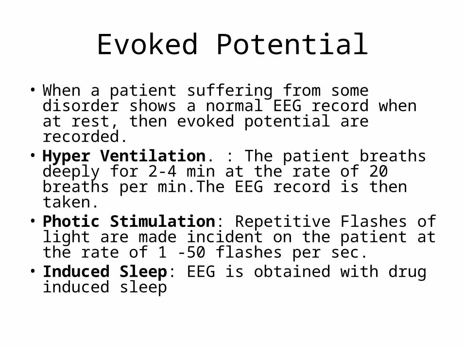
• When a patient suffering from some disorder shows a normal EEG record when at rest, then evoked potential are recorded.
• Hyper Ventilation. : The patient breaths deeply for 2-4 min at the rate of 20 breaths per min.The EEG record is then taken.
• Photic Stimulation: Repetitive Flashes of light are made incident on the patient at the rate of 1 -50 flashes per sec.
• Induced Sleep: EEG is obtained with drug induced sleep

Brain Computer Interface
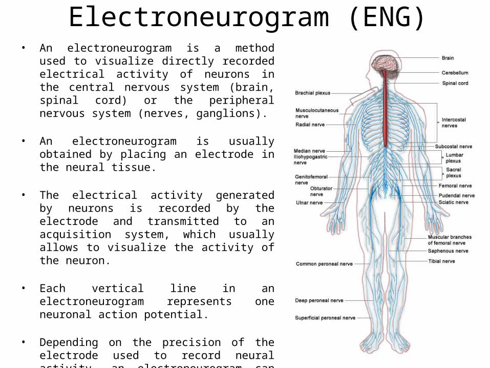
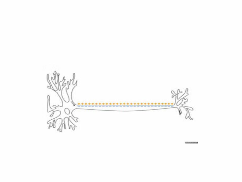
Electroneurogram (ENG)• An electroneurogram is a method used to
visualize directly recorded electrical activity of neurons in the central nervous system (brain, spinal cord) or the peripheral nervous system (nerves, ganglions).
• An electroneurogram is usually obtained by placing an electrode in the neural tissue.
• The electrical activity generated by neurons is recorded by the electrode and transmitted to an acquisition system, which usually allows to visualize the activity of the neuron.
• Each vertical line in an electroneurogram represents one neuronal action potential.
• Depending on the precision of the electrode used to record neural activity, an electroneurogram can contain the activity of a single neuron to thousands of neurons.
Electroneurogram (ENG)• Conduction velocity and latency in a peripheral nerve are the most generally useful
parameters associated with peripheral nerve function.
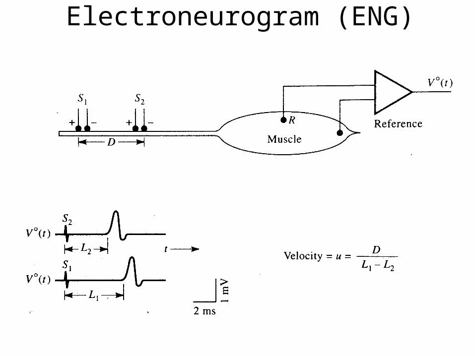
• It is measured by stimulating a motor nerve at two points a known distance apart along its course.
• Subtraction of shorter latency from longer latency gives the conduction time along the segment of nerve between the stimulating electrodes. Knowing the separating distance, the conduction velocity can be determined.
• Conduction velocity has potential clinical value.
• In a regenerating nerve fiber, conduction velocity is slowed following nerve injury.
Electroneurogram (ENG)
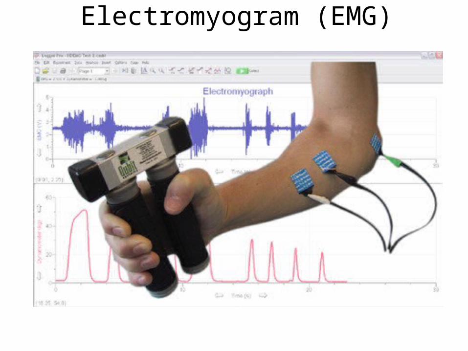
Electromyogram (EMG)• The bioelectric potential associated with muscle activity constitute the
electromyogram (EMG).
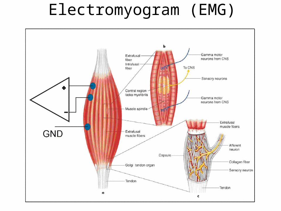
• Muscle is organized functionally on the basis of the motor unit.
• A motor unit is defined as one motor neuron and all of the muscle fibers it innervates.
• When a motor unit fires, the impulse (action potential) is carried down the motor neuron to the muscle. The area where the nerve contacts the muscle is called the neuromuscular junction, or the motor end plate.
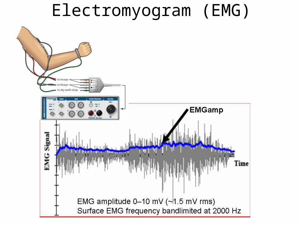
• The potentials are measured at the surface of the body, near a muscle of interest or directly from the muscle by penetrating the skin with needle electrodes.
• EMG potentials range between less than 50 μV and up to 20 to 30 mV, depending on the muscle under observation.
Electromyogram (EMG)
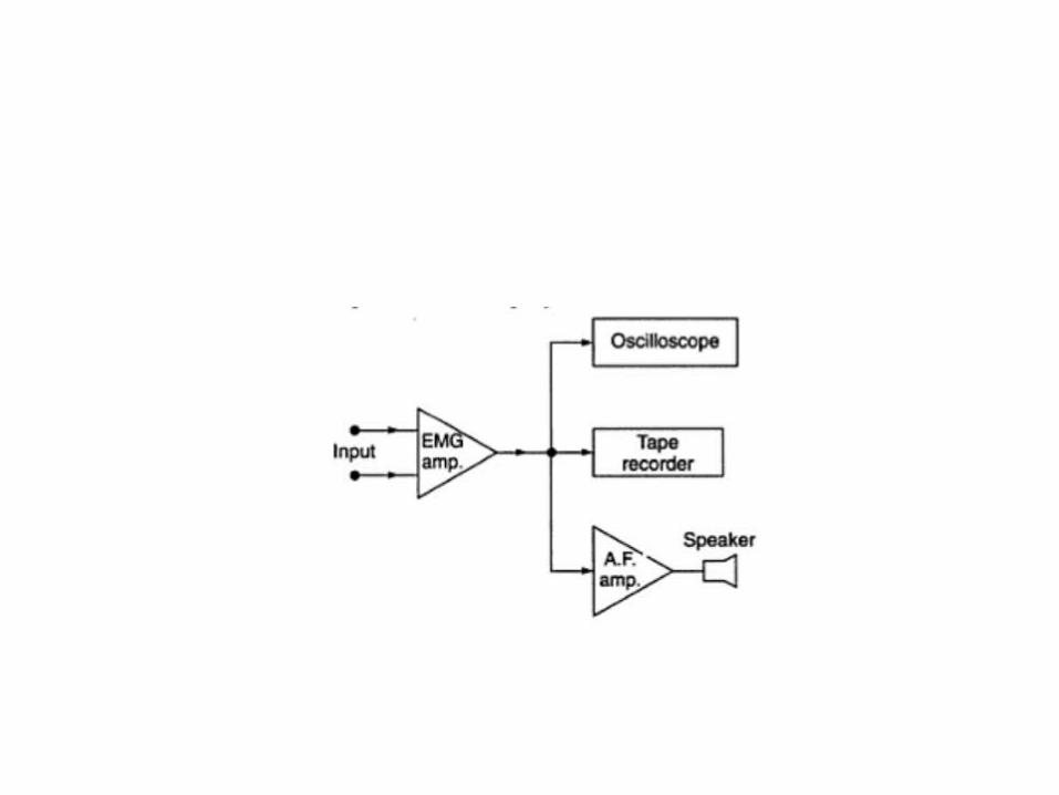
Electromyogram (EMG)• The EMG pattern is usually a summation of the individual action potentials from the
fibers consisting the muscle or muscles being measured.
• The signals can be analyzed to detect medical abnormalities, activation level, recruitment order or to analyze the biomechanics of human or animal movement.
• There are two kinds of EMG in widespread use: 1. Surface EMG
2. Intramuscular (needle and fine-wire) EMG. A needle electrode or a needle containing two fine-wire electrodes is inserted
through the skin into the muscle tissue.
• Abnormal spontaneous activity might indicate some nerve and/or muscle damage
• The shape, size, and frequency of the resulting motor unit potentials are analyzed.
• The composition of the motor unit, the number of muscle fibres per motor unit, the metabolic type of muscle fibres and many other factors affect the shape of the motor unit potentials in the myogram.
Electromyogram (EMG)
Electromyogram (EMG)
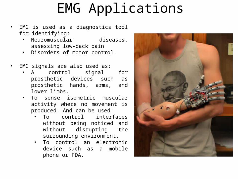
EMG Applications• EMG is used as a diagnostics tool for
identifying:• Neuromuscular diseases, assessing low-
back pain• Disorders of motor control.
• EMG signals are also used as:• A control signal for prosthetic devices
such as prosthetic hands, arms, and lower limbs.
• To sense isometric muscular activity where no movement is produced. And can be used:• To control interfaces without being
noticed and without disrupting the surrounding environment.
• To control an electronic device such as a mobile phone or PDA.

Electromyogram (EMG)• EMG signals have been targeted as control for flight systems.
• The Human Senses Group at the NASA Research Center at Moffett Field, CA seeks to advance man-machine interfaces by directly connecting a person to a computer.
• An EMG signal is used to substitute for mechanical joysticks and keyboards.
• EMG has also been used in research towards a "wearable cockpit," which employs EMG-based gestures to manipulate switches and control sticks necessary for flight in conjunction with a goggle-based display.
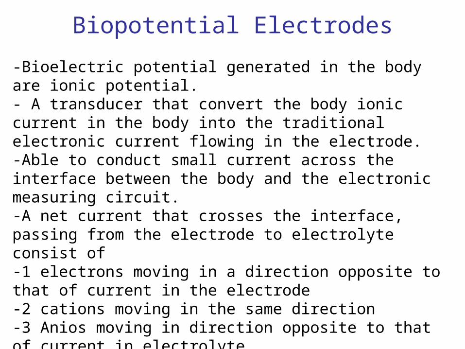
Biopotential Electrodes
-Bioelectric potential generated in the body are ionic potential.- A transducer that convert the body ionic current in the body into the traditional electronic current flowing in the electrode.-Able to conduct small current across the interface between the body and the electronic measuring circuit.-A net current that crosses the interface, passing from the electrode to electrolyte consist of-1 electrons moving in a direction opposite to that of current in the electrode-2 cations moving in the same direction-3 Anios moving in direction opposite to that of current in electrolyte
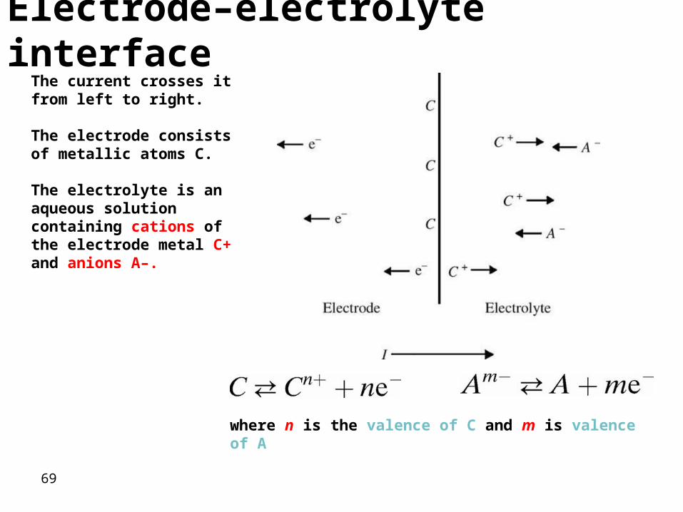
fig_05_01
The current crosses it from left to right.
The electrode consists of metallic atoms C.
The electrolyte is an aqueous solution containing cations of the electrode metal C+ and anions A–.
Electrode–electrolyte interface
where n is the valence of C and m is valence of A
69

Electrode-Electrolyte Interface
Oxidation reaction causes atom to lose electronReduction reaction causes atom to gain electron
Oxidation is dominant when the current flow is from electrode to electrolyte, and reduction dominate when the current flow is in the opposite.

• Electrode is made up of same atoms of the same material as the cations
Half-Cell Potential
• When the metal comes in contact with solution, The electrolyte surrounding the metal is at different electric potential from rest of the solution.
• A second electrode is required to find halfcell potential- hydrogen
• Half-Cell potential is determined by
- Metal involved
- Concentration of its ion in solution
- Temperature
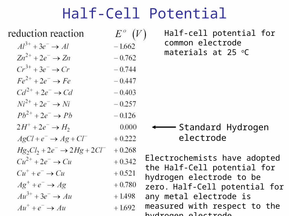
Half-Cell PotentialHalf-cell potential for common electrode materials at 25 oC
Standard Hydrogen electrode
Electrochemists have adopted the Half-Cell potential for hydrogen electrode to be zero. Half-Cell potential for any metal electrode is measured with respect to the hydrogen electrode.
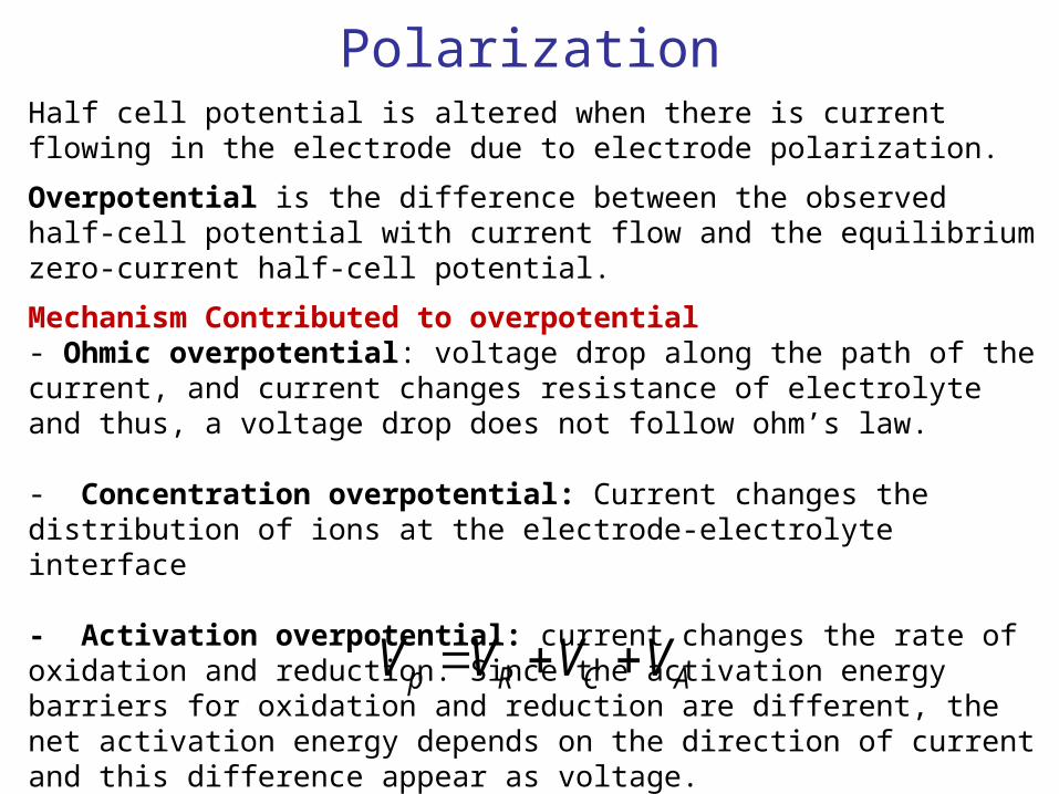
PolarizationHalf cell potential is altered when there is current flowing in the electrode due to electrode polarization.
Overpotential is the difference between the observed half-cell potential with current flow and the equilibrium zero-current half-cell potential.
Mechanism Contributed to overpotential- Ohmic overpotential: voltage drop along the path of the current, and current changes resistance of electrolyte and thus, a voltage drop does not follow ohm’s law.
- Concentration overpotential: Current changes the distribution of ions at the electrode-electrolyte interface
- Activation overpotential: current changes the rate of oxidation and reduction. Since the activation energy barriers for oxidation and reduction are different, the net activation energy depends on the direction of current and this difference appear as voltage.
ACRp VVVV
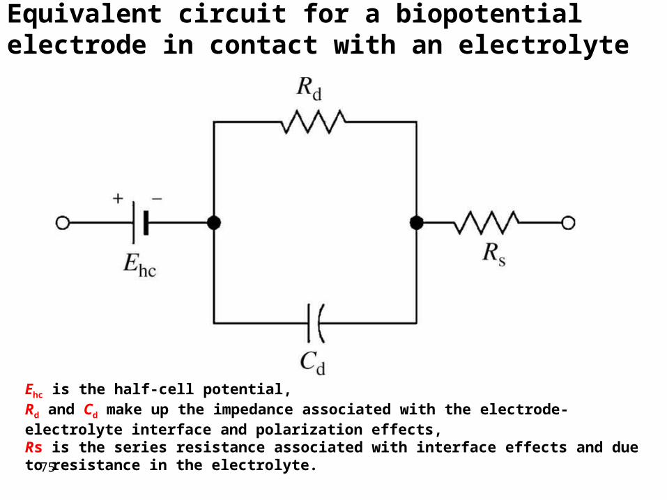
Ehc is the half-cell potential, Rd and Cd make up the impedance associated with the electrode-electrolyte interface and polarization effects, Rs is the series resistance associated with interface effects and due to resistance in the electrolyte.
Equivalent circuit for a biopotential electrode in contact with an electrolyte
75

Half Cell Potential and Nernst Equation
2
1lna
a
nF
RTE
neCC n
When two ionic solutions of different concentration are separated by semipermeable membrane, an electric potential exists across the membrane.
a1 and a2 are the activity of the ions on each side of the membrane.Ionic activity is the availability of an ionic species in solution to enter into a reaction.Note: ionic activity most of the time equal the concentration of the ion
BA
DC
aa
aa
nF
RTEE ln0
If the activity is not unity (activity does not equal concentration) then the cell potential is
neDCBA
For the general oxidation-reduction reaction, the Nernst equation for half cell potential is
nCa
nF
RTEE ln0

Polarizable and Nonpolarizable Electrodes
Perfectly Polarizable Electrodes
Electrodes in which no actual charge crosses the electrode-electrolyte interface when a current is applied. The current across the interface is a displacement current and the electrode behaves like a capacitor. Overpotential is due concentration. Example : Platinum electrode
Perfectly Non-Polarizable Electrode
Electrodes in which current passes freely across the electrode-electrolyte interface, requiring no energy to make the transition. These electrodes see no overpotentials. Example: Ag/AgCl Electrode
Example: Ag-AgCl is used in recording while Pt is used in stimulation

The Silver/Silver Chloride ElectrodeApproach the characteristic of a perfectly nonpolarizable electrodeAdvantage of Ag/AgCl is that it is stable in liquid that has large quantity of Cl- such as the biological fluid.
Ag
AgCl
eAgAg
AgClClAg
Cl
Ag/AgCl exhibits less electric noise than the equivalent metallic Ag electrode.
1.5 v
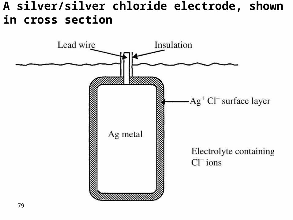
A silver/silver chloride electrode, shown in cross section
79

Properties of bioelectrodes
• Good conductors.• low impedance.• They should not polarize when a current flows through
them.• They should establish a good contact with the body and
not cause motion.• They should not cause itching swelling or discomfort to
the patient.• The metal should not be toxic.• Mechanically rugged.• Easy to clean.
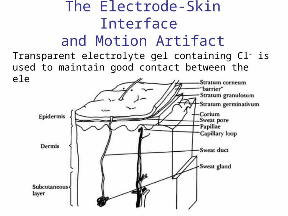
The Electrode-Skin Interface and Motion Artifact
Transparent electrolyte gel containing Cl- is used to maintain good contact between the electrode and the skin.
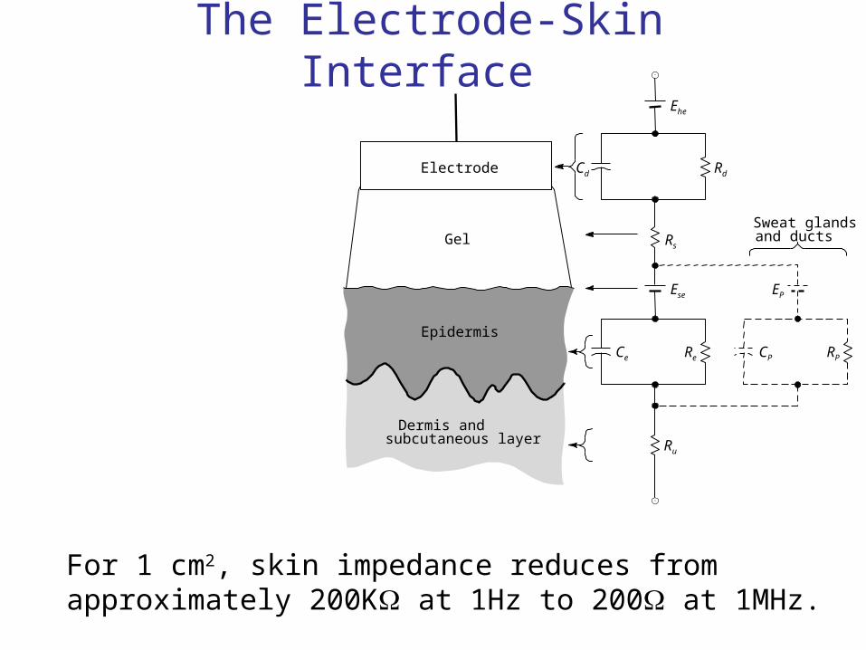
The Electrode-Skin Interface
Sweat glandsand ducts
Electrode
Epidermis
Dermis andsubcutaneous layer Ru
Re
Ese
Ehe
Rs
RdCd
EP
RPCPCe
Gel
For 1 cm2, skin impedance reduces from approximately 200K at 1Hz to 200 at 1MHz.
Motion Artifact When polarizable electrode is in contact with an electrolyte, a double layer of charge forms at the interface. Movement of the electrode will disturb the distribution of the charge and results in a momentary change in the half cell potential until equilibrium is reached again. Motion artifact is less minimum for nonpolarizable electrodes.
Signal due to motion has low frequency so it can be filtered out when measuring a biological signal of high frequency component such as EMG or axon action potential. However, for ECG, EEG and EOG whose frequencies are low it is recommended to use nonpolarizable electrode to avoid signals due to motion artifact.
Metal Plate Electrode• One of the most frequently used forms of biopotential electrodes is
the metal-plate electrode.
• It consists of a metallic conductor in contact with the skin.
• An electrolyte soaked pad or gel is used to establish and maintain the contact.
• Two types
• Cylindrical Type
• Disk type
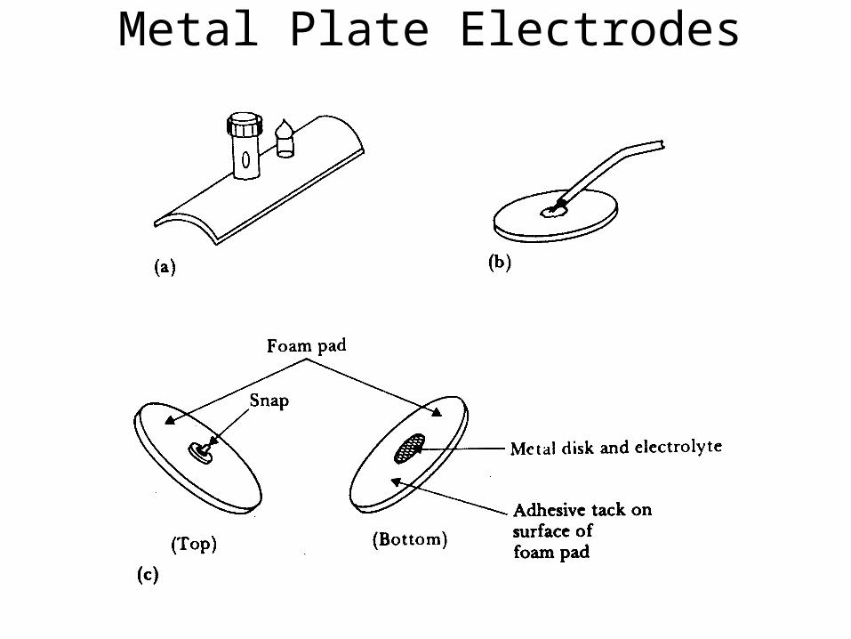
Metal Plate Electrodes
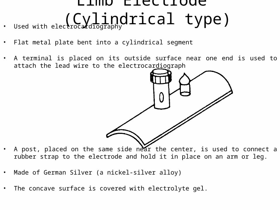
Limb Electrode (Cylindrical type)• Used with electrocardiography
• Flat metal plate bent into a cylindrical segment
• A terminal is placed on its outside surface near one end is used to attach the lead wire to the electrocardiograph
• A post, placed on the same side near the center, is used to connect a rubber strap to the electrode and hold it in place on an arm or leg.
• Made of German Silver (a nickel-silver alloy)
• The concave surface is covered with electrolyte gel.
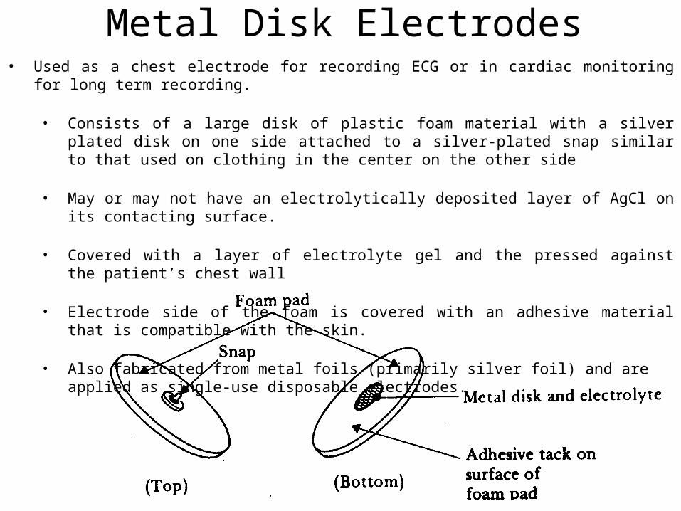
Metal Disk Electrodes• Used as a chest electrode for recording ECG or in cardiac monitoring for long term recording.
• Consists of a large disk of plastic foam material with a silver plated disk on one side attached to a silver-plated snap similar to that used on clothing in the center on the other side
• May or may not have an electrolytically deposited layer of AgCl on its contacting surface.
• Covered with a layer of electrolyte gel and the pressed against the patient’s chest wall
• Electrode side of the foam is covered with an adhesive material that is compatible with the skin.
• Also fabricated from metal foils (primarily silver foil) and are applied as single-use disposable electrodes.
Metal Disk Electrodes
• In recording EMGs
• Stainless steel, platinum or gold plated disks are used to minimize the chance that electrode will enter into chemical reaction with perspiration or the gel.
• Produce polarizable electrodes.
• Motion artifacts can be a problem with active patients.
• It is the momentary change in the half-cell potential of the electrode-electrolyte interface due to the mechanical movement of the electrode with respect to the electrolyte.
• Smaller in diameter compared to electrodes used in ECGs
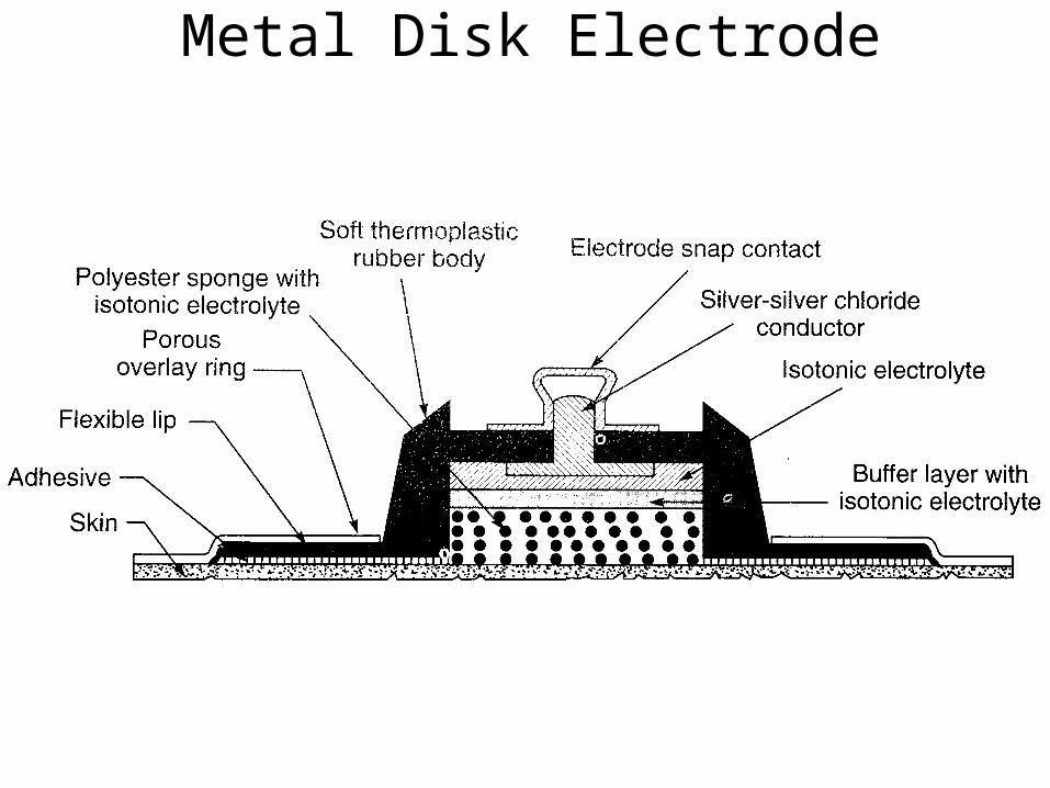
Metal Disk Electrode
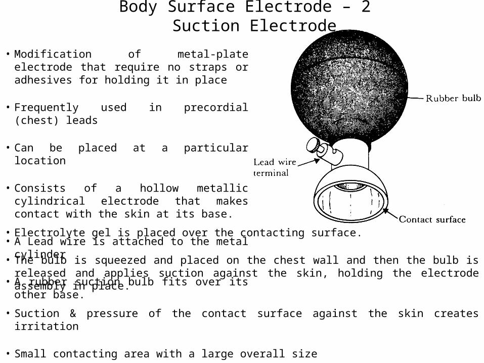
Body Surface Electrode – 2Suction Electrode
• Modification of metal-plate electrode that require no straps or adhesives for holding it in place
• Frequently used in precordial (chest) leads
• Can be placed at a particular location
• Consists of a hollow metallic cylindrical electrode that makes contact with the skin at its base.
• A Lead wire is attached to the metal cylinder
• A rubber suction bulb fits over its other base.
• Electrolyte gel is placed over the contacting surface.
• The bulb is squeezed and placed on the chest wall and then the bulb is released and applies suction against the skin, holding the electrode assembly in place.
• Suction & pressure of the contact surface against the skin creates irritation
• Small contacting area with a large overall size
• Higher source impedance compared to other metal type surface electrodes.
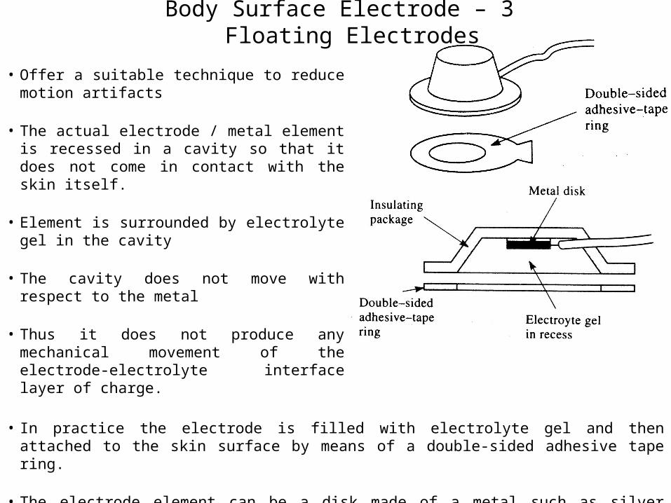
Body Surface Electrode – 3Floating Electrodes
• Offer a suitable technique to reduce motion artifacts
• The actual electrode / metal element is recessed in a cavity so that it does not come in contact with the skin itself.
• Element is surrounded by electrolyte gel in the cavity
• The cavity does not move with respect to the metal
• Thus it does not produce any mechanical movement of the electrode-electrolyte interface layer of charge.
• In practice the electrode is filled with electrolyte gel and then attached to the skin surface by means of a double-sided adhesive tape ring.
• The electrode element can be a disk made of a metal such as silver coated with AgCl.
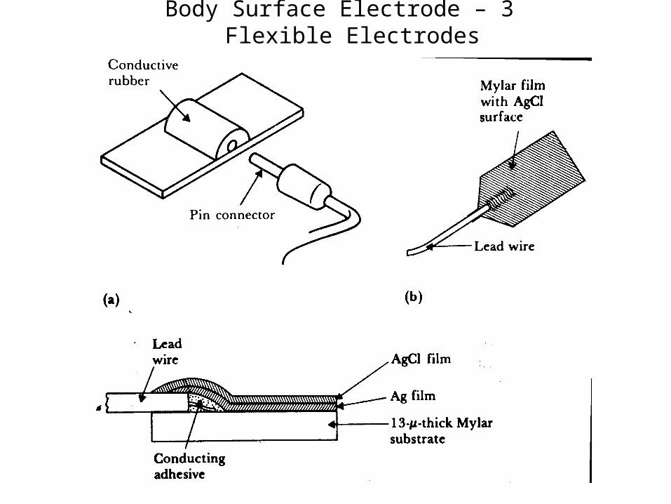
Body Surface Electrode – 3Flexible Electrodes
Internal Electrodes
• Used within the body to detect biopotentials
• The electrode itself or the lead wire crosses the skin (percutaneous electrodes)
• Can be entirely placed inside (internal electrodes) • For implanted electronics circuits such as radio telemetry transmitter.
• Entirely different from body surface electrodes• They do not have to contend with the electrolyte-skin interface and its associated limitations.
• The skin itself is the electrolyte for the electrode-electrolyte interface.
• No electrolyte gel is required to maintain this interface, because extracellular fluid is present.
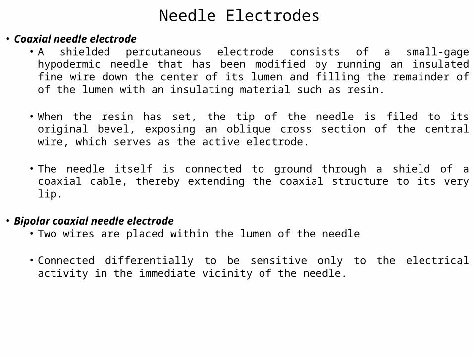
Needle Electrodes• Consists of a solid needle, usually made of stainless steel, with a sharp point.
• The shank of the needle is insulated with a coating such as an insulating varnish; only the tip is left exposed.
• A lead wire is attached to the other end of the needle, and the joint is encapsulated in a plastic hub to protect it.
• Frequently used in electromyography.
• Principally for acute measurements, because their stiffness and size make them uncomfortable for long term implantation.
• When it is placed in particular muscle, it obtains an EMG from that muscle acutely and can be then removed.
• The electrode consists of stainless steel hypodermic needles placed subcutaneously on each limb.
• Lead wires with special connectors attached to the needle at the hub connects the electrodes to the instrument.
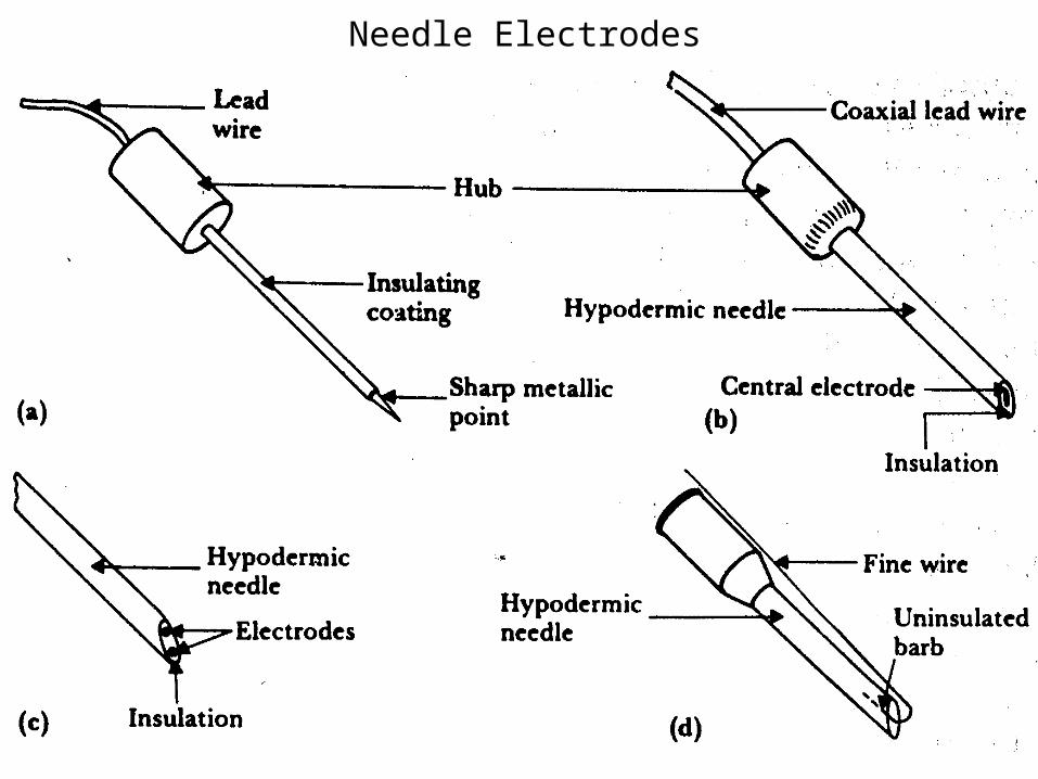
Needle Electrodes• Coaxial needle electrode
• A shielded percutaneous electrode consists of a small-gage hypodermic needle that has been modified by running an insulated fine wire down the center of its lumen and filling the remainder of of the lumen with an insulating material such as resin.
• When the resin has set, the tip of the needle is filed to its original bevel, exposing an oblique cross section of the central wire, which serves as the active electrode.
• The needle itself is connected to ground through a shield of a coaxial cable, thereby extending the coaxial structure to its very lip.
• Bipolar coaxial needle electrode• Two wires are placed within the lumen of the needle
• Connected differentially to be sensitive only to the electrical activity in the immediate vicinity of the needle.
Needle Electrodes
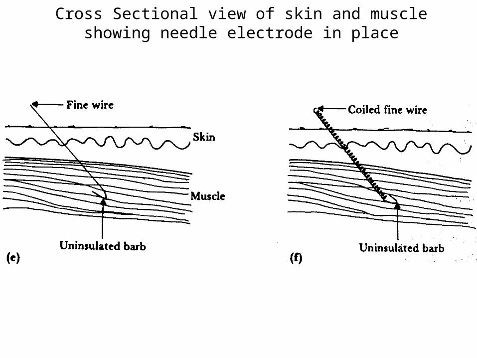
Cross Sectional view of skin and muscle showing needle electrode in place
Internal Electrodes
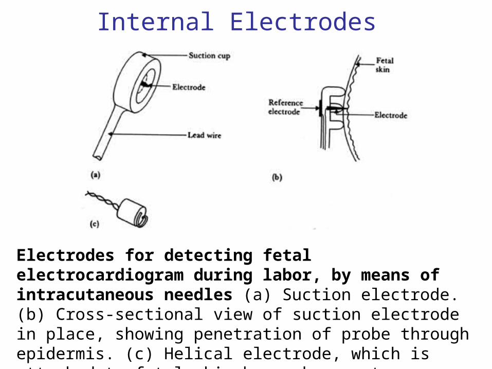
Electrodes for detecting fetal electrocardiogram during labor, by means of intracutaneous needles (a) Suction electrode. (b) Cross-sectional view of suction electrode in place, showing penetration of probe through epidermis. (c) Helical electrode, which is attached to fetal skin by corkscrew type action.
Schemes of Introducing electrodes into the skin
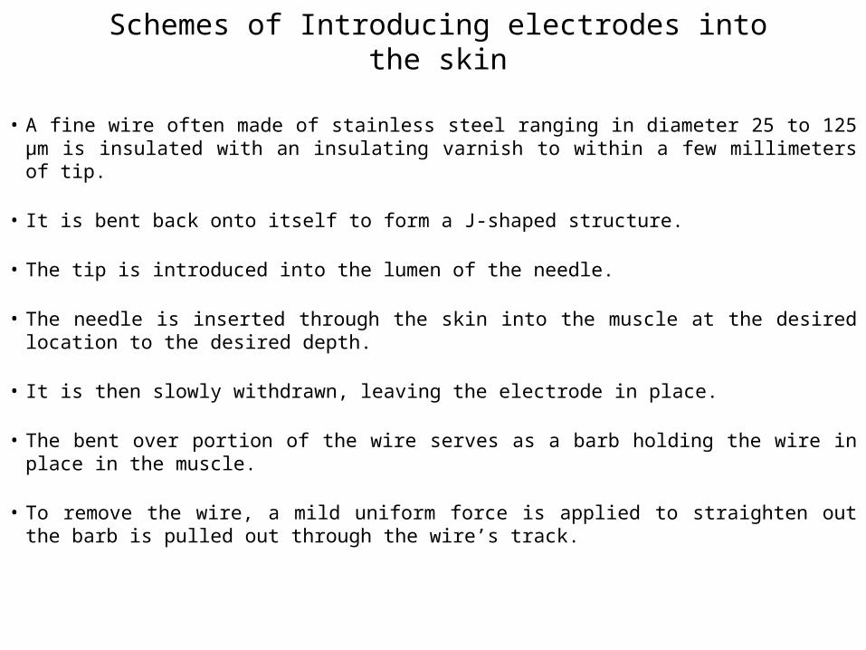
• A fine wire often made of stainless steel ranging in diameter 25 to 125 µm is insulated with an insulating varnish to within a few millimeters of tip.
• It is bent back onto itself to form a J-shaped structure.
• The tip is introduced into the lumen of the needle.
• The needle is inserted through the skin into the muscle at the desired location to the desired depth.
• It is then slowly withdrawn, leaving the electrode in place.
• The bent over portion of the wire serves as a barb holding the wire in place in the muscle.
• To remove the wire, a mild uniform force is applied to straighten out the barb is pulled out through the wire’s track.
Schemes of Introducing electrodes into the skin
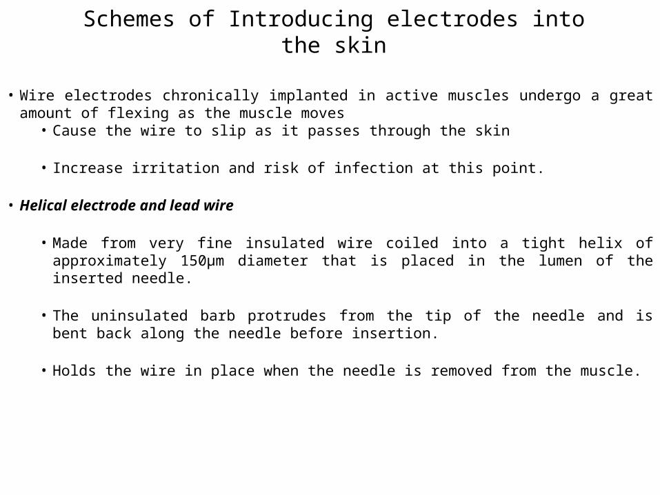
• Wire electrodes chronically implanted in active muscles undergo a great amount of flexing as the muscle moves
• Cause the wire to slip as it passes through the skin
• Increase irritation and risk of infection at this point.
• Helical electrode and lead wire
• Made from very fine insulated wire coiled into a tight helix of approximately 150µm diameter that is placed in the lumen of the inserted needle.
• The uninsulated barb protrudes from the tip of the needle and is bent back along the needle before insertion.
• Holds the wire in place when the needle is removed from the muscle.
Microelectrodes
• To measure potential across the cell membrane
• Smaller in size with respect to the cell dimension • Avoids causing serious injury
• Doesn’t change the cell’s behavior.
• Tip diameter ranging from approximately 0.05 to 10µm
• Formed from • Solid-metal needles
• Or a Metal contained within or on the surface of a glass needle
• A glass micropipette having a lumen filled with an electrolytic solution.
• Two types• Metal
• Micropipette
Metal Microelectrodes
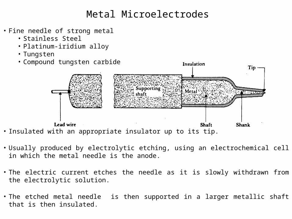
• Fine needle of strong metal• Stainless Steel• Platinum-iridium alloy• Tungsten• Compound tungsten carbide
• Insulated with an appropriate insulator up to its tip.
• Usually produced by electrolytic etching, using an electrochemical cell in which the metal needle is the anode.
• The electric current etches the needle as it is slowly withdrawn from the electrolytic solution.
• The etched metal needle is then supported in a larger metallic shaft that is then insulated.
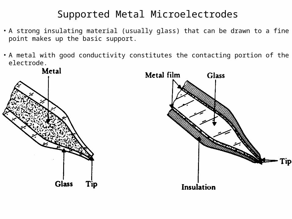
Supported Metal Microelectrodes
• A strong insulating material (usually glass) that can be drawn to a fine point makes up the basic support.
• A metal with good conductivity constitutes the contacting portion of the electrode.
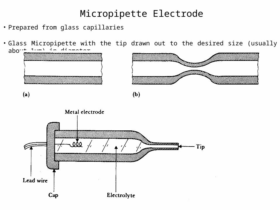
Micropipette Electrode• Prepared from glass capillaries
• Glass Micropipette with the tip drawn out to the desired size (usually about 1µm) in diameter.
Micropipette Electrode
• Prepared from glass capillaries
• Glass Micropipette with the tip drawn out to the desired size (usually about 1µm) in diameter.
• The central region of a piece of capillary tubing is heated to the softening point
• It is then rapidly stretched to produce the constriction
• Is then broken apart at the constriction to produce a pipette structure.
• Filled with an electrolyte solution frequently 3M KCL
• A Cap containing a metal electrode is then sealed to the pipette.
Practical Hints in using Electrodes
• Electrode and any part of the lead wire that may be exposed to the electrolyte must be all of the same material.
• A third material such as solder should not be used to connect the electrode to its lead unless it is certain that this material will not be in contact with the electrolyte.
• Provide mechanical bonding
• When pairs of electrodes are used for measuring differentials,its better to use the same material for each electrode.
• Electrodes placed on the skin’s surface have a tendency to come off.
• Lead wires to the surface electrodes should be extremely flexible and strong.
Practical Hints in using Electrodes
• Insulation of these electrodes usually made of a polymeric material, so it can absorb water.
• The input impedance of amplifier to which the electrodes are connected must be higher than the source impedance.
• Dissimilar metals should not be used in contact because their half cell potentials are different.
• Using a tapered region of insulation that gradually increases from the diameter of the wire to one closer to that of the electrode often minimizes the problem of breakage at the point at which the lead wire enter the electrode.
Biopotential Amplifiers
• The essential function of a biopotential amplifier is to take a weak electric signal of biological origin.
• They Must have high input impedance. (10 M ohm)• The input circuit of a biopotential amplifier must also
provide protection to the organism being studied.• The output circuit of a biopotential amplifier does not
present so many critical problems as the input circuit.• Biopotential amplifiers must operate in that portion of the
frequency spectrum in which the biopotentials that they amplify exist.
• Quick calibration