BINGO - isprs.org
7
Integrated Sensor Orientation – Two Examples to show the Potential of simultaneous GPS/IMU and Image Data Processing J. Kremer* and E. Kruck** (*) IGI mbH, Kreuztal, Germany (**) GIP Eng, Aalen, Germany Keywords: aerial triangulation, GPS, INS, GPS/INS, sensor orientation Abstract The simultaneous processing of GPS/IMU data and image information for the determination of the elements of exterior orientation (EO) in an extended aerial triangulation software (Integrated Sensor Orientation – ISO) combines the advantages of conventional aerial triangulation and the direct measurement of the EO with GPS/IMU systems. With this technique a very high accuracy and reliability can be achieved without the need of a large number of ground control points (GCPs). Especially for projects where the installation of GCPs is dangerous or expensive and the accuracy requirements are very high, the combination of both methods is the fastest and cheapest way to get high quality georeferenced aerial photographs. In this paper, the potential of ISO is shown with help of two example projects. The “Allamakee Project” consists of a block of 10 by 12 aerial photos, the “Qaqortoq Projects” consists of five partly overlapping single strips. For these projects the GPS/IMU system CCNS/AEROcontrol of IGI, Germany, and the aerial triangulation software BINGO of GIP, Germany, have been employed successfully. 1. Introduction In the last years, the discussion about the use of directly measured Exterior Orientation parameters (EO) for photogrammetric data processing was often focused on the question, whether Direct Georeferencing (DG)(or Direct Sensor Orientation, cp. [1, 2]) is possible for certain projects, or not. By now, it has been shown in many publications, that DG became an operational technique (e.g. [3]). Nevertheless, for many applications DG is not the optimal approach. For most of these projects, the use of EO measured with a GPS/IMU system can still bring large benefits, if the EO is used as additional information in an AT. In this paper the potential of this Integrated Sensor Orientation should be shown for two different tasks – the orientation of a block of photos, and for the orientation of a track. 2. Integrated Sensor Orientation (ISO) vs. Direct Georeferencing (DG) The use of directly measured EO in photogrammetric data processing can generally be distinguished in two different concepts: The use of directly measured image EO for photogrammetric data processing without conducting an AT over the entire image block presents the principle of DG. On the other hand, the simultaneous processing of GPS/IMU data and image information for the determination of the EO in an extended aerial triangulation is referred to as Integrated Sensor Orientation (ISO) [2]. Which approach is suitable for a specific project depends on many factors, e.g. the required accuracy, the image scale, the availability of ground control information and GPS base stations and the accessibility of the project area. 2.1. Direct Georeferencing The advantages of DG are obvious: No AT, no tie point measurements and no Ground Control Points (GCPs) are needed for the complete block. These advantages lead not only to substantial cost reductions compared to traditional georeferencing using AT or GPS assisted AT, but also to much shorter processing times. Nevertheless, for the purpose of the boresight alignment, highly accurate AT results of a small calibration field are still needed to determine the attitude differences between the image sensor coordinate system and the IMU coordinate system (e.g. [4]). A disadvantage of “pure” DG is the missing redundancy. Problems in the calculations, like the use of wrong GPS base station coordinates or errors in the transformation of the results to the used mapping system, will directly affect the final results.
Transcript of BINGO - isprs.org

Integrated Sensor Orientation – Two Examples to show the Potential of simultaneous GPS/IMU and Image Data Processing
J. Kremer* and E. Kruck**
(*) IGI mbH, Kreuztal, Germany (**) GIP Eng, Aalen, Germany
Keywords: aerial triangulation, GPS, INS, GPS/INS, sensor orientation Abstract The simultaneous processing of GPS/IMU data and image information for the determination of the elements of exterior orientation (EO) in an extended aerial triangulation software (Integrated Sensor Orientation – ISO) combines the advantages of conventional aerial triangulation and the direct measurement of the EO with GPS/IMU systems. With this technique a very high accuracy and reliability can be achieved without the need of a large number of ground control points (GCPs). Especially for projects where the installation of GCPs is dangerous or expensive and the accuracy requirements are very high, the combination of both methods is the fastest and cheapest way to get high quality georeferenced aerial photographs. In this paper, the potential of ISO is shown with help of two example projects. The “Allamakee Project” consists of a block of 10 by 12 aerial photos, the “Qaqortoq Projects” consists of five partly overlapping single strips. For these projects the GPS/IMU system CCNS/AEROcontrol of IGI, Germany, and the aerial triangulation software BINGO of GIP, Germany, have been employed successfully. 1. Introduction In the last years, the discussion about the use of directly measured Exterior Orientation parameters (EO) for photogrammetric data processing was often focused on the question, whether Direct Georeferencing (DG)(or Direct Sensor Orientation, cp. [1, 2]) is possible for certain projects, or not. By now, it has been shown in many publications, that DG became an operational technique (e.g. [3]). Nevertheless, for many applications DG is not the optimal approach. For most of these projects, the use of EO measured with a GPS/IMU system can still bring large benefits, if the EO is used as additional information in an AT. In this paper the potential of this Integrated Sensor Orientation should be shown for two different tasks – the orientation of a block of photos, and for the orientation of a track. 2. Integrated Sensor Orientation (ISO) vs. Direct Georeferencing (DG) The use of directly measured EO in photogrammetric data processing can generally be distinguished in two different concepts: The use of directly measured image EO for photogrammetric data processing without conducting an AT over the entire image block presents the principle of DG. On the other hand, the simultaneous processing of GPS/IMU data and image information for the determination of the EO in an extended aerial triangulation is referred to as Integrated Sensor Orientation (ISO) [2]. Which approach is suitable for a specific project depends on many factors, e.g. the required accuracy, the image scale, the availability of ground control information and GPS base stations and the accessibility of the project area. 2.1. Direct Georeferencing The advantages of DG are obvious: No AT, no tie point measurements and no Ground Control Points (GCPs) are needed for the complete block. These advantages lead not only to substantial cost reductions compared to traditional georeferencing using AT or GPS assisted AT, but also to much shorter processing times. Nevertheless, for the purpose of the boresight alignment, highly accurate AT results of a small calibration field are still needed to determine the attitude differences between the image sensor coordinate system and the IMU coordinate system (e.g. [4]). A disadvantage of “pure” DG is the missing redundancy. Problems in the calculations, like the use of wrong GPS base station coordinates or errors in the transformation of the results to the used mapping system, will directly affect the final results.

Furthermore, simple geometrical considerations [5] show that even if the conditions are perfect and all calculations are correct, the reachable accuracy of DG might not be sufficient for very large scale photo projects. 2.2. Integrated Sensor Orientation For ISO the advantage of not needing AT and tie point measurements is traded for a more error tolerant and more precise orientation procedure. This procedure also eliminates the need for a special boresight calibration, because the needed calibration parameters can be calculated inside the AT. Since each method, the AT and the direct measurement are capable to determine the EO alone, the combination of both brings a maximum accuracy, reliability and error tolerance. It is shown in this paper, that the number of GCPs for ISO can safely be reduced to a minimum without a serious deterioration of the final result. The disadvantage of the needed AT can be reduced by using automatic tie point matching. The matching process can strongly be accelerated and improved by using the “raw” EO from the GPS/IMU system. 3. Description of the used Hardware and Software For both described projects the GPS/IMU system AEROcontrol-IId from IGI was used. The ISO was performed with the AT program BINGO from GIP. 3.1. GPS/IMU System The configuration of the used GPS/IMU system AEROcontrol-IId configuration is described in detail in [5]. Figure 1 shows the AEROcontrol-IId together with the CCNS4 (Computer Controlled Navigation System). Figures 3 and 6 show the aerial cameras with the mounted IMUs. For the dGPS calculation, the GrafNav 6.03 software package from Waypoint Consulting Inc., Canada was used, the GPS/IMU calculations was done with AEROoffice 4.07 from IGI.
Figure 1: AEROcontrol-IId: airborne computer with integrated GPS receiver, IMU and GPS antenna 3.2. AT Software The operated AT software BINGO is described e.g. in [7, 8, 9]. Figure 2 shows the graphical user interface of the software during processing one of the example projects.

Figure 2: BINGO graphical user interface 4. Example Projects 4.1. Integrated Sensor Orientation of a Block – The Allamakee Project On June 17th 2003 a block of 176 photos was flown by ASI, Aerial Services Inc., Iowa, USA, in the northeast corner of Iowa. The photos in the block had a forward overlap of 60% and sideward overlap of 30%. The flying height above ground was app. 4800m. The used camera was a LMK 1000 with a 153mm lens cone.
Figure 3: LMK 1000 with mounted IMU-IId Figure 4: Piper Cheyenne used for the Allamakee project

Figure 5: Allamakee Project: Flightpath and Footprints The number of satellites during the mission was between 6 and 8. The maximum distance from the base station to a photo was 63km. For the AT of the area, 90 permanent GCPs were equally distributed in the block, 146 photos of the block have been evaluated. In a first step, the uncalibrated EO parameters and 90 GCPs were used to find a reference solution with optimal accuracy. The first calculation showed that one GCP had to be omitted because of an obvious position error. A calculation with the other 89 GCPs and the uncalibrated EO showed the expected good result. The estimated accuracy on the ground was app. 0.1m in the horizontal component and app. 0.2 m in the vertical component. In the second step, the calculation was repeated with only one GCP, located approximately in the middle of the area. The other 88 GCPs were used as independent checkpoints, only. The residuals at the checkpoints and the difference between both solutions at random points in the area are given in Table 1. ∆X [cm] (RMS) ∆Y [cm] (RMS) ∆Z [cm] (RMS) Checkpoint Residual 20.7 23.8 51.9 Difference to Reference Solution (89 GCPs)
4.6 8.8 20.1
Table 1: Comparison between ISO with 89 GCPs and ISO with one GCP. It is obvious for this project that the large number of used GCPs was not necessary. However, the wrong GCP shows that one could have run into problems, if only one GCP would have been used. For this project, the number of GCPs could have safely been reduced to four to six points without loosing the opportunity to find a single wrong GCP. This means, in the given case the number of GCPs could have safely been reduced by 95%!

4.2. Integrated Sensor Orientation of a Track – The Qaqortoq Project The Qaqortoq Project was flown by Scankort A/S, Staastrup, Denmark, on July 24th in the southern part of Greenland. The project was consisting of 55 photos taken in 5 partly overlapping lines (figure 7), forward overlap was 60%. The flying height above ground was app. 3000m resulting in an image scale of 1:20000. Scankort used a RMK-Top 15 camera and Agfa N400 film. The images were scanned on a Phodis SCAI scanner with 21 microns resolution. The number of satellites during the mission was between 6 and 10. The maximum distance from the base station to a photo was 30 km.
Figure 6: Interior of Scankorts Piper Navajo, equipped Figure 7: Qaqortoq Project: Flightpath and Footprints with a RMK-TOP 15 with IGI IMU-IId To get a height model and orthophotos for the complete project, Scankort used the following workflow: For the northern three strips the ISO with 21 GCPs and the uncalibrated EO was used. The boresight angles from this area were used as calibration for the two southern strips. The directly measured EO was operated to derive a height model (7m grid) of the area and to create orthophotos (the orthophotos were calculated with COWS (complete ortho workflow system)). Figure 8 shows a mosaic of two orthophotos. On the limit between the two photos (in the middle of figure 8) almost no pixel shift can be seen. This shows, that
a) The exterior orientation is correct. b) The derived height model is accurate.
To verify that the AT results for the northern part gives the same result for boresight calibration with much less GCPs, the AT was repeated with only four points. Points in the overlapping areas and on both ends were selected. Roll [gon] Pitch [gon] Yaw [gon] ISO with 21 GCPs -0.0307 0.0803 -0.0954 ISO with 4 GCPs -0.0322 0.0785 -0.0956 Table 2: Comparison of the boresight angles with ISO with 21 and ISO with four GCPs The results in table 2 show, that the results for both runs are within 1.8 mgon. The radial symmetric lens distortion, that was calculated within the AT showed the same results. The small difference shows, that for the boresight calibration with these three strips, only four GCPs would have been enough. During the calculation of the AT of the northern part, it could be seen that the used GCPs had a systematic error in the height. Due to a wrong geoid model, the height error was up to 0.5m over the project area. After the error was detected, he could be corrected easily. This incident shows that, like in the Allamakee project, the use of 4 to 6 GCPs in the ISO was necessary to get the correct result.
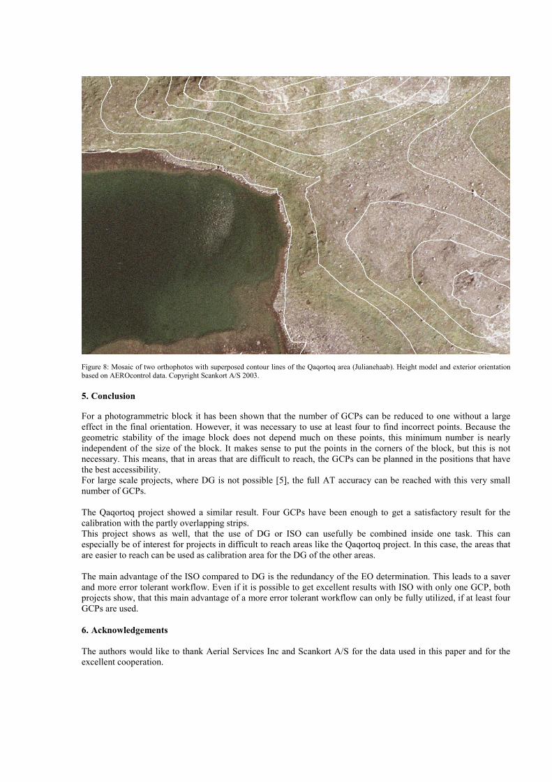
Figure 8: Mosaic of two orthophotos with superposed contour lines of the Qaqortoq area (Julianehaab). Height model and exterior orientation based on AEROcontrol data. Copyright Scankort A/S 2003. 5. Conclusion For a photogrammetric block it has been shown that the number of GCPs can be reduced to one without a large effect in the final orientation. However, it was necessary to use at least four to find incorrect points. Because the geometric stability of the image block does not depend much on these points, this minimum number is nearly independent of the size of the block. It makes sense to put the points in the corners of the block, but this is not necessary. This means, that in areas that are difficult to reach, the GCPs can be planned in the positions that have the best accessibility. For large scale projects, where DG is not possible [5], the full AT accuracy can be reached with this very small number of GCPs. The Qaqortoq project showed a similar result. Four GCPs have been enough to get a satisfactory result for the calibration with the partly overlapping strips. This project shows as well, that the use of DG or ISO can usefully be combined inside one task. This can especially be of interest for projects in difficult to reach areas like the Qaqortoq project. In this case, the areas that are easier to reach can be used as calibration area for the DG of the other areas. The main advantage of the ISO compared to DG is the redundancy of the EO determination. This leads to a saver and more error tolerant workflow. Even if it is possible to get excellent results with ISO with only one GCP, both projects show, that this main advantage of a more error tolerant workflow can only be fully utilized, if at least four GCPs are used. 6. Acknowledgements The authors would like to thank Aerial Services Inc and Scankort A/S for the data used in this paper and for the excellent cooperation.

7. References [1] Schwarz, K.P. et al., 1993. An Integrated INS/GPS Approach to the Georeferencing of Remotely Sensed
Data, PE&RS, 59(11): 1167-1674
[2] Heipke, C. et al., 2001. The OEEPE Test on Integrated Sensor Orientation, OEEPE Workshop on Integrated Sensor Orientation, Hannover
[3] Fritsch, D., 2000. Performance of the IGI AEROcontrol-IId GPS/Inertial System – Final Report, Available on request from IGI
[4] Cramer, M., Stallmann, D., 2002. System Calibration for Direct Georeferencing. International Archives on Photogrammetry and Remote Sensing IAPRS, Volume XXXIV, Com. III, Part A, pages 79-84, ISPRS Commission III Symposium, Graz
[5] Kremer, J., 2002. CCNS / AEROcontrol - an Integrated GPS/IMU System for Direct Georeferencing of Airborne Image Data, Symposium Gyro Technology 2002, Sorg, H. (editor), Stuttgart, 16.0-16.9
[6] Kremer, J., 2001. CCNS and AEROcontrol: Products for Efficient Photogrammetric Data Collection, Photogrammetric Week´01, Fritsch/Spiller (Eds.), Wichmann Verlag, Heidelberg: 85-92
[7] Kruck, E. et al., 1996. Advanced Combined Bundle Block Adjustment with Kinematic GPS Data. Presented Paper, ISPRS Comm. III/1, Vienna 1996.
[8] Kruck, E., 2001. Combined IMU Sensor Calibration and Bundle Adjustment with BINGO-F. OEEPE Workshop “Integrated Sensor Orientation”, Hannover, September 2001.
[9] Kruck, E., 2003. Rotations of Space and Coordinate Transformations, ISPRS Working Group I/5, Workshop Barcelona Sept. 2003.