Node.js: Continuation-Local-Storage and the Magic of AsyncListener
Big Data Processing Technologies
Chentao WuAssociate Professor
Dept. of Computer Science and [email protected]

Schedule
• lec1: Introduction on big data and cloud computing
• Iec2: Introduction on data storage
• lec3: Data reliability (Replication/Archive/EC)
• lec4: Data consistency problem
• lec5: Block level storage and file storage
• lec6: Object-based storage
• lec7: Distributed file system
• lec8: Metadata management

Collaborators
Contents
Introduction on Storage Devices1

An Example Memory Hierarchy
registers
on-chip L1
cache (SRAM)
main memory
(DRAM)
local secondary storage
(local disks)
Larger,
slower,
and
cheaper
(per byte)
storage
devices
remote secondary storage
(tapes, distributed file systems, Web servers)
Local disks hold files retrieved from disks on
remote network servers.
Main memory holds disk blocks retrieved from local
disks.
off-chip L2
cache (SRAM)
L1 cache holds cache lines retrieved from the L2 cache memory.
CPU registers hold words retrieved from L1 cache.
L2 cache holds cache lines retrieved from main memory.
L0:
L1:
L2:
L3:
L4:
L5:
Smaller,
faster,
and
costlier
(per byte)
storage
devices

Read Only Memory (ROM)When a computer is first switched on, it needs to load up the BIOS (Basic Input/Output System) and basic instructions for the hardware.
These are stored in ROM (Read Only Memory).
This type of memory is called non-volatile because it retains the data.
Data stored in ROM remains there even when the computer is switched off.
ROM can be found on the motherboard.

Random Access Memory (RAM)Computers store temporary data in the RAM (Random Access Memory). These could be operating instructions, loose bits of data or content from programs that are running.
The contents of RAM are constantly rewritten as the data is processed.
When the computer is switched off, all the data is cleared from the RAM.
This type of memory is called volatilebecause it only stores the data whilst the computer is switched on.
RAM sticks are found on the motherboard.

Secondary Storage/Backup StorageComputers need backing storage outside the CPU to store data and programs not currently in use.There are three main types of storage device:
Those that store data by magnetizing a special material that coats the surface of a disk.
Those that store data using optical technology to etch the data onto a plastic-coated metal disk. Laser beams are then passed over the surface to read the data.
Flash drives use solid state technology and store data in a similar way to the BIOS chip.
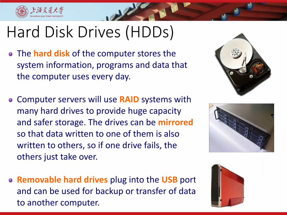
Hard Disk Drives (HDDs)The hard disk of the computer stores the system information, programs and data that the computer uses every day.
Computer servers will use RAID systems with many hard drives to provide huge capacity and safer storage. The drives can be mirroredso that data written to one of them is also written to others, so if one drive fails, the others just take over.
Removable hard drives plug into the USB port and can be used for backup or transfer of data to another computer.

What’s Inside A Disk Drive?Spindle
Arm
Actuator
Platters
Electronics
SCSI
connector
Image courtesy of Seagate Technology
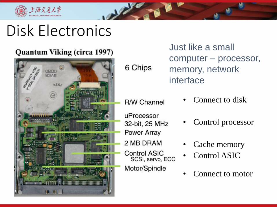
Disk Electronics
• Connect to disk
• Control processor
• Cache memory
• Control ASIC
• Connect to motor
Just like a small
computer – processor,
memory, network
interface
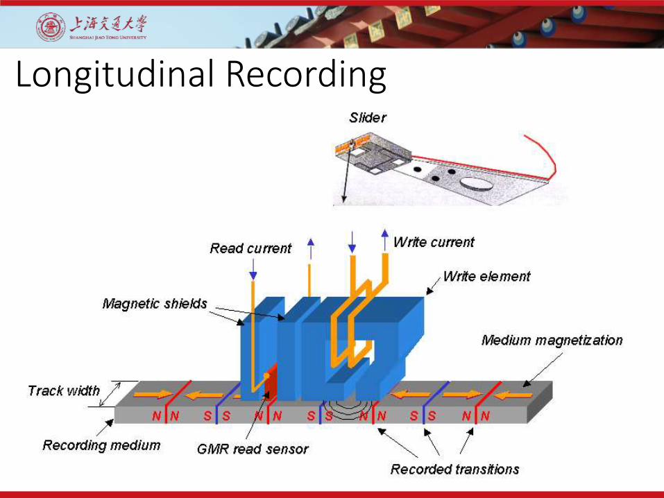
Longitudinal Recording
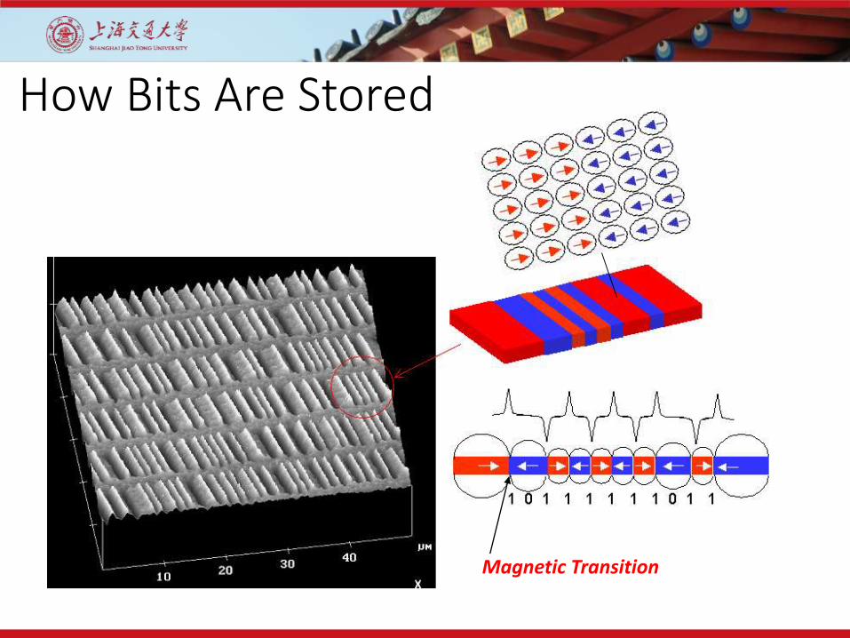
How Bits Are Stored
Magnetic Transition

Disk “Geometry”Disks contain platters, each with two surfaces
Each surface organized in concentric rings called tracks
Each track consists of sectors separated by gaps
spindle
surfacetracks
track k
sectors
gaps
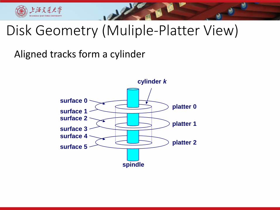
Disk Geometry (Muliple-Platter View)
surface 0
surface 1surface 2
surface 3surface 4
surface 5
cylinder k
spindle
platter 0
platter 1
platter 2
Aligned tracks form a cylinder
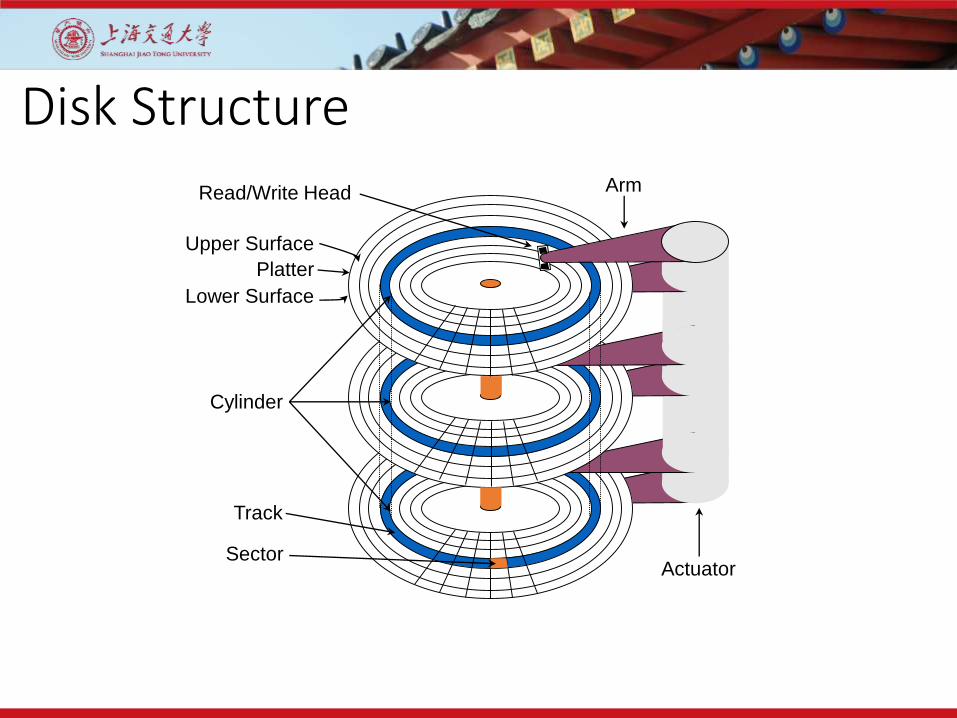
Disk Structure
Read/Write Head
Upper Surface
Platter
Lower Surface
Cylinder
Track
Sector
Arm
Actuator

Disk Structure - top view of single platter
Tracks divided into sectors
Surface organized into tracks

Disk Access
Head in position above a track
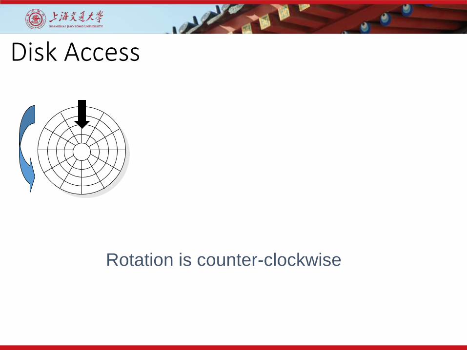
Disk Access
Rotation is counter-clockwise

Disk Access – Read
About to read blue sector
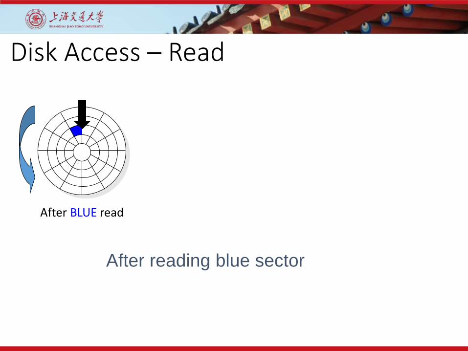
Disk Access – Read
After BLUE read
After reading blue sector
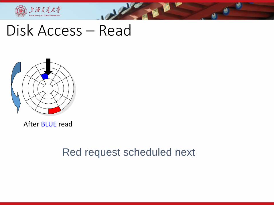
Disk Access – Read
After BLUE read
Red request scheduled next

Disk Access – Read
After BLUE read Seek for RED
Seek to red’s track
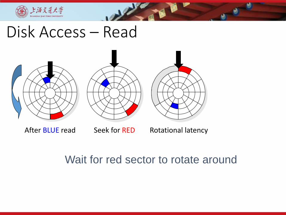
Disk Access – Read
After BLUE read Seek for RED Rotational latency
Wait for red sector to rotate around
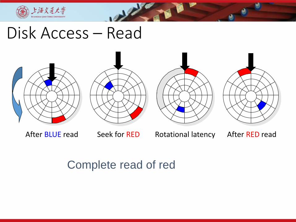
Disk Access – Read
After BLUE read Seek for RED Rotational latency After RED read
Complete read of red

Disk Access – Read
After BLUE read Seek for RED Rotational latency After RED read
Seek
Rotational Latency
Data Transfer
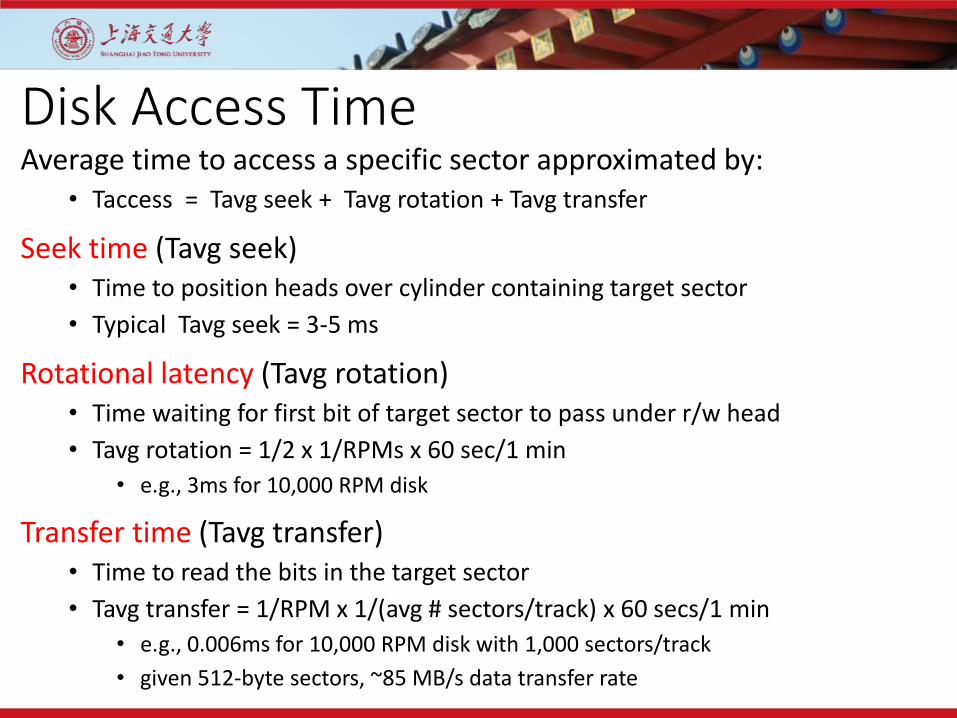
Disk Access TimeAverage time to access a specific sector approximated by:
• Taccess = Tavg seek + Tavg rotation + Tavg transfer
Seek time (Tavg seek)• Time to position heads over cylinder containing target sector
• Typical Tavg seek = 3-5 ms
Rotational latency (Tavg rotation)• Time waiting for first bit of target sector to pass under r/w head
• Tavg rotation = 1/2 x 1/RPMs x 60 sec/1 min
• e.g., 3ms for 10,000 RPM disk
Transfer time (Tavg transfer)• Time to read the bits in the target sector
• Tavg transfer = 1/RPM x 1/(avg # sectors/track) x 60 secs/1 min
• e.g., 0.006ms for 10,000 RPM disk with 1,000 sectors/track
• given 512-byte sectors, ~85 MB/s data transfer rate

Solid State Drives

Flash Memory Cell
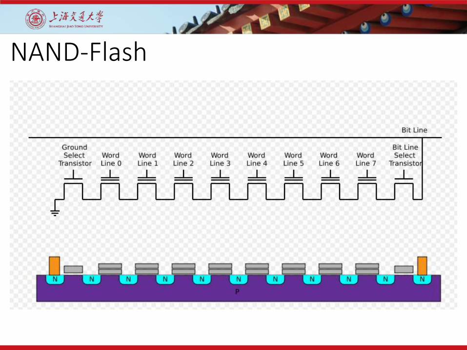
NAND-Flash
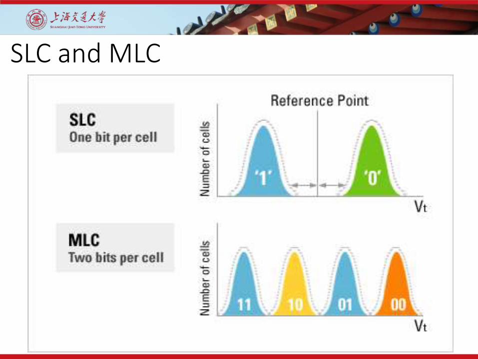
SLC and MLC
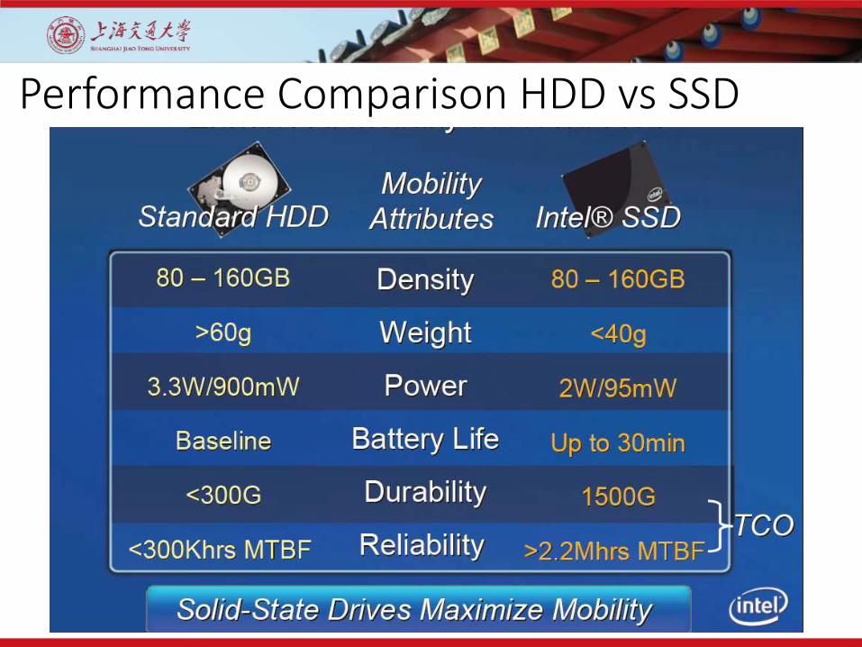
Performance Comparison HDD vs SSD

Performance Comparison HDD vs SSD
Contents
Introduction to RAID2

RAID Array Components
RAIDController
Hard Disks
Logical Array(RAID Sets)
RAID Array
Host
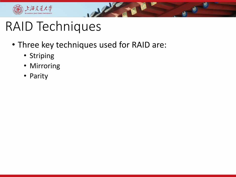
RAID Techniques• Three key techniques used for RAID are:
• Striping
• Mirroring
• Parity

RAID Technique – Striping
RAIDController
Host
Stripe
Strip
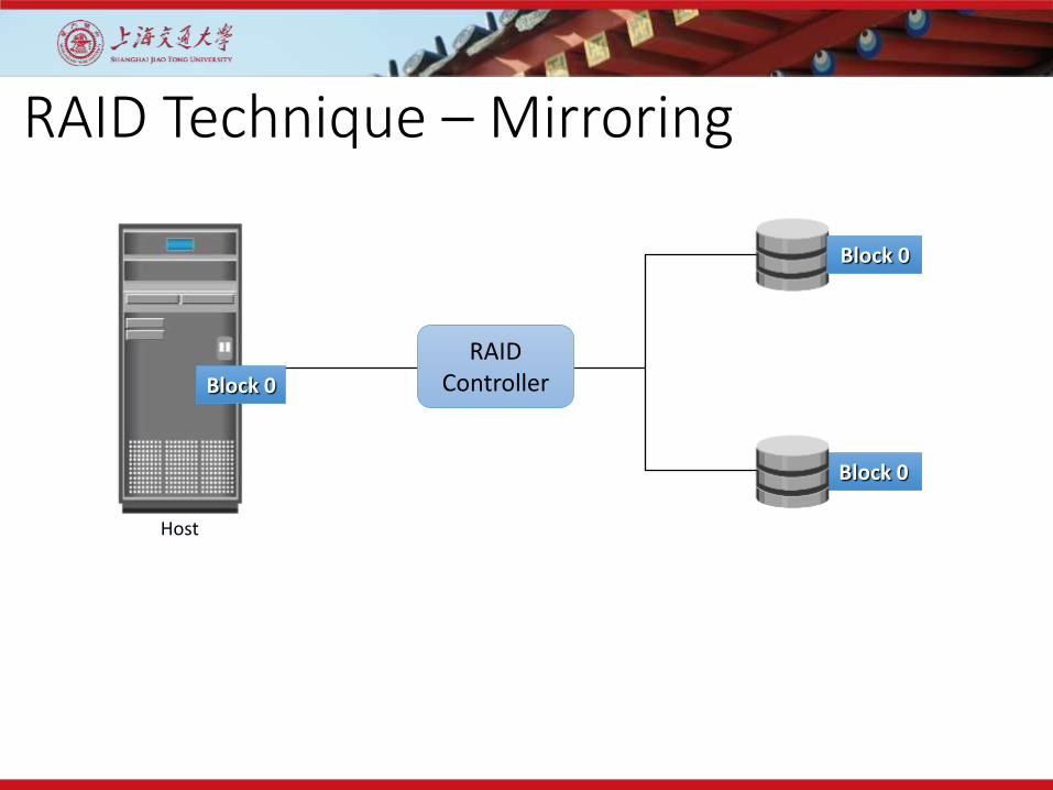
RAID Technique – Mirroring
Host
Block 0
RAIDController
Block 0
Block 0
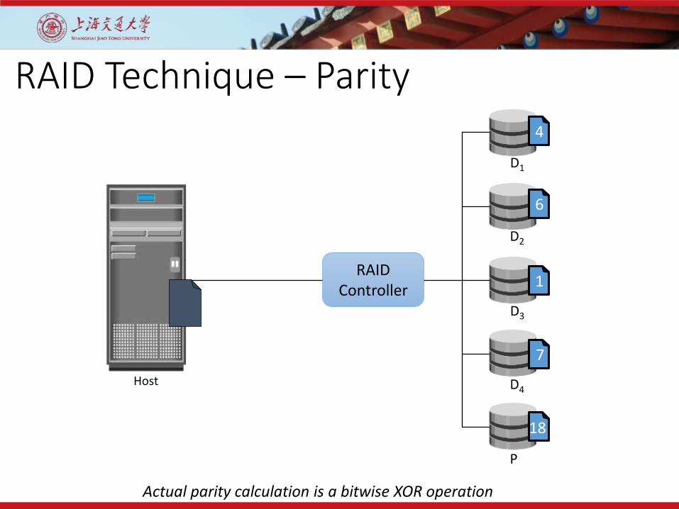
RAID Technique – Parity
RAIDController
D1
D2
D3
D4
P
4
6
1
7
18
Host
Actual parity calculation is a bitwise XOR operation
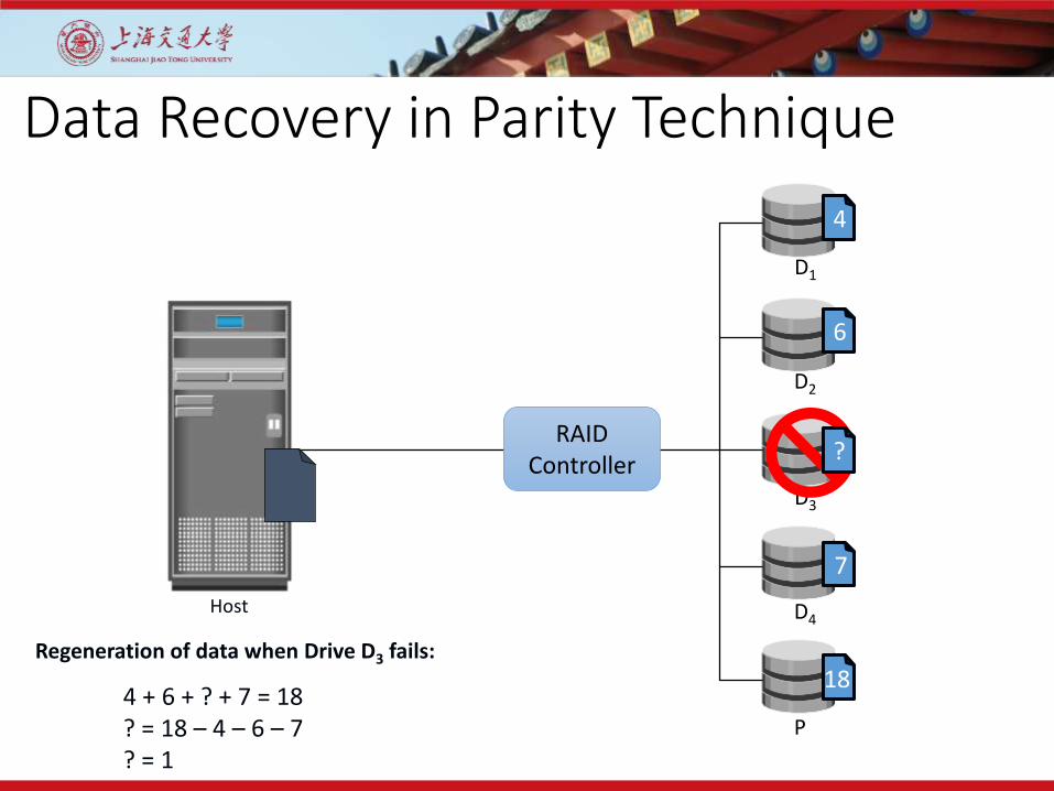
Data Recovery in Parity Technique
Host
4 + 6 + ? + 7 = 18? = 18 – 4 – 6 – 7? = 1
Regeneration of data when Drive D3 fails:
D1
D2
D3
D4
P
4
6
?
7
18
RAIDController

RAID-0• It splits data among two or more disks.
• Provides good performance.
• Lack of data redundancy means there is no fail over support with this configuration.
• In the diagram to the right, the odd blocks are written to disk 0 and the even blocks to disk 1 such that A1, A2, A3, A4, … would be the order of blocks read if read sequentially from the beginning.
• Used in read only NFS systems and gaming systems.

RAID-1• RAID1 is ‘data mirroring’.
• Two copies of the data are held on two physical disks, and the data is always identical.
• Twice as many disks are required to store the same data when compared to RAID 0.
• Array continues to operate so long as at least one drive is functioning.
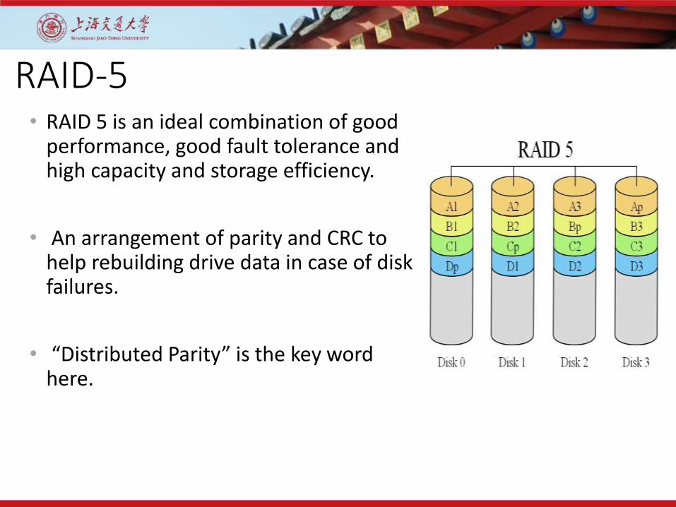
RAID-5• RAID 5 is an ideal combination of good
performance, good fault tolerance and high capacity and storage efficiency.
• An arrangement of parity and CRC to help rebuilding drive data in case of disk failures.
• “Distributed Parity” is the key word here.

RAID-6• It is seen as the best way to guarantee
data integrity as it uses double parity.
• Lesser MTBF compared to RAID5.
• It has a drawback though of longer write time.
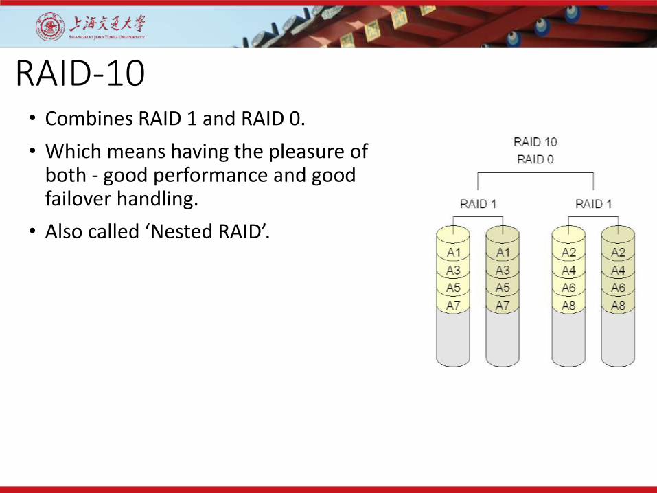
RAID-10• Combines RAID 1 and RAID 0.
• Which means having the pleasure of both - good performance and good failover handling.
• Also called ‘Nested RAID’.

Implementations
Software based RAID:
• Software implementations are provided by many Operating Systems.
• A software layer sits above the disk device drivers and provides an abstraction layer between the logical drives(RAIDs) and physical drives.
• Server's processor is used to run the RAID software.
• Used for simpler configurations like RAID0 and RAID1.

Implementations (Contd.)
Hardware based RAID:
• A hardware implementation of RAID requires at least a special-purpose RAID controller.
• On a desktop system this may be built into the motherboard.
• Processor is not used for RAID calculations as a separate controller present.A PCI-bus-based, IDE/ATA hard disk RAID
controller, supporting levels 0, 1, and 01.
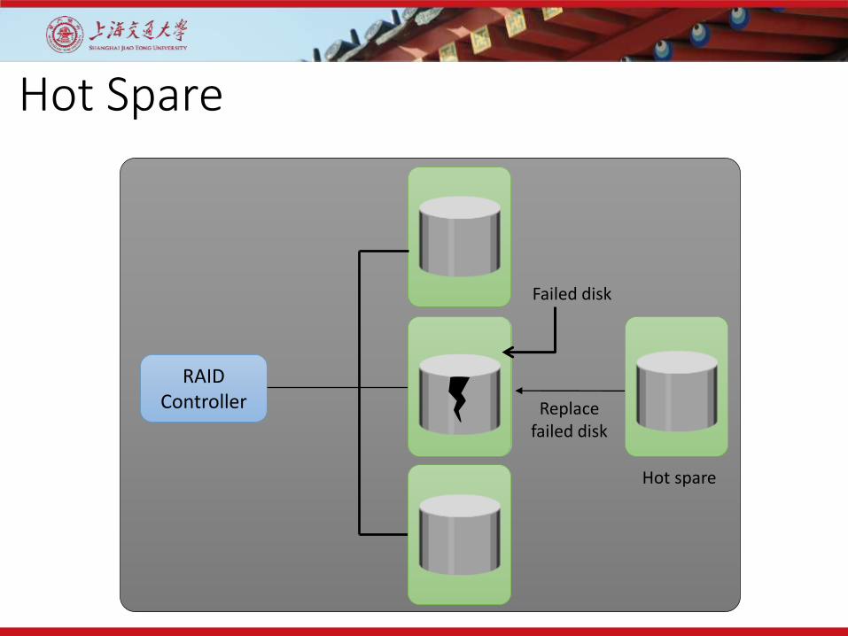
Hot Spare
Hot spare
Failed disk
Replace failed disk
RAIDController

Thank you!