BIG - vintagemachinery.orgvintagemachinery.org/pubs/2133/17106.pdf · Back gears for added power...
16
Transcript of BIG - vintagemachinery.orgvintagemachinery.org/pubs/2133/17106.pdf · Back gears for added power...


"BIG SHAPER" ACCURACY and FEATURES
SHAPER TABLE AND CROSS RAIL Table . . . three "T" slots on top of table and two "T" slots on side. "V" slot for shaping bars also provided on side of table. Front end support for maximum rigidity under heavy cuts. Swivel table is not standard equipment but can be supplied at extra price. Swivel table moves on horizontal axis at any angle and this movement is registered against a protractor scale. Swivel table is locked by means of three "T" bolts in circular "T" slots to secure rigidity of clamping. Table cross feed screw has a large well marked micrometer dial. Crank swings wide of all controls and makes it easy and fast to move table manually in either direction. Bronze covered felt wipers for all dovetail ways on shapero The cross rail of substantial proportions is stress ribbed with broadly spaced ways. A tapered gib to slide provides compensation for any wear. The cross rail lock is an added protection to lock cross rail and table assembly into position after moving table up or down to insure accurate results.
FEED HOUSING FRONT Automatic cross feeds are available in both directions. Feed screw mounted in bronze quills with a ball thrust bearing. Feed direction control can be set in three positions to control the direction of table travel- right, left or neutral for manual feed.
BACK GEARS Back gears for added power are quick acting type controlled by back gear lever safely located at rear of shapero
RAM AND ROCKER ARM Ram of semi-steel casting is heavily ribbed to resist distortion under heavy loads and is of sufficient length to provide a minimum of 60 % bearing surface on ways even when ram is at maximum stroke and completely forward in ram bearings. Ram positioner is located on the operating side of the ram for easy hand positioning of ram when locating ram in relation to work. The ram clamp is conveniently located on top of ram, securely locks the ram in desired position. The stroke indicator is large and easily seen and clearly shows the length of stroke taken in increments <1f Yz". The shaft for adjusting the length of stroke has a crank handle for use when quickly changing or setting required length of stroke. The sliding block of the rocker arm is made of manganese bronze and operates in the rocker arm made of a semi-steel casting.
TOOL HEAD The tool head is graduated into 120°, included, for quick and accurate set-up. Tapered gibs provide take-up to assure permanent accuracy even after long wear. The tool head swivel locks will lock the head at any desired angle for the "hard to get at places" on many pieces. The tool head box lock locks the tool head box in
2
position so that regardless of the tool slide angle, the tool can be adjusted for proper swing-away clearance. The tool slide handle has a large well marked micrometer collar at correct angle so that it can be easily seen from standing position at the machine. The correct depth of the cut can be quickly calculated and tool moved accordingly. The tool slide lock will lock the tool slide in position so that extreme accuracy and trueness can be maintained. The dials on the machine are friction-type for quick adjustment, accurately graduated to .001".
TABLE FEED SHAFT The elevating shaft moves table and cross rail assembly up and down by means of a crank, moving the work into position.
BODY Column is rigidly designed with exceptionally wide dovetails and is substantially ribbed and reinforced to withstand extreme thrust and torsional strain. The pedestal is of braced box design with sufficient extra width and length to properly support machine for all its operations. The pedestal also fully encloses the variable speed motor drive, eliminating completely the dangers of exposed pulleys and belts. Motor and drive located in the pedestal are easily accessible by removing large cover plates.
FEED ADJUSTMENT The feed adjuster has a large friction knurled knob so that with a turn of the knob, the pinion is released and can be quickly set for varying amounts of feed from .0025" to .0175" per stroke.
BULL GEAR Helical type bull gear with tapered bearing mountings so positioned in relation to bearings that overhang is kept at an absolute minimum. The center distance between bull gear and pinion adjustable for tooth wear.
CLUTCH ASSEMBLY The clutch mechanism is of the very latest design, especially constructed for use in machine tools. The clutch lever is conveniently located on the operating side of the ram with a long, easy grip handle which enables the operator to stop all mechanical motion of shaper without turning off electrical current and secures instantaneous action for mechanical power.
MOTOR DRIVE ASSEMBLY The motor switch is conveniently and safely loca on the lower forward side. The variable speed drive permits speeds wide speed range of 12 to 180 strokes Speed changes are effected instantly chine is in operation by turning con handwheel. Indicator shows which direction to wheel for faster or slower speeds.
VISE A single screw action swivel vise opening to 6". Graduations are


SHELOON CHICAGO u. S. A.

SPECIFICATIONS SPINDLE
Size of taper ....................... . Hole through spindle . . . . . . . . . •••• t • • •
SPEEDS
3000P with low speed pulley . . . • • • • • ••
with high speed pulley ... ..... .
(Both pulleys supplied as standard equipment)
3000PQ-Same speeds as 3000P with additional speeds in back gear.
With low speed pulley . .... .
With high speed pulley . . . . •
(Both pulleys supplied as standard equipment)
FEEDS
Longitudinal (with hand-screw) . . . . . . • Longitudinal (with hand-lever) .. .... . Transverse. . . . . . . . . . . . . . . . . Vertical (maximum distance table top
to center line of spindle) .......... . Longitudinal power feed on Model
3000PQ machines provide table feeds of .0008", .0016", .0032", and . 0064" per spindle revolution.
Longitudinal power feed on Model 3000P machines provide table feeds of . 003", .005", and . 008" per spindle revolution.
TABLE
Size . . . . . .. . . . . . . . . . . .. .. J • • • • • • • • • Number of Tee Slots ........... .. . . . Width of Tee Slots . ................ . Table is arranged for coolant with two troughs and two drain cups, cast as integral unit.
VISE
Width of jaws . . . . . . . . . . . . . . . . . . . . . • Depth of jaws ................... .. . Opens with steel jaws ............... . Opens without steel jaws .......... .. . Overall height with swivel base ...... . Overall height as plain vise .......... .
MOTOR
No.9 B&S !!{6"
125 to 55 0 RP.M.
225 to 1100 RP.M.
25 to 100 RP.M.
36 to 198 RP.M.
12" 10"
5 Yz"
9 :!4"
5 Yz" x 22Ys" 3
Horsepower and speed recommended for maximum efficiency of operation. . .. 1 H P x 175 0
RP.M.
DIMENSIONS AND WEIGHTS
Height overall ............. ........ . Floor space required ............ . ' .. . . Base dimensions. . .. . . . . . . . . ... . .. . Net weight (approx.) ............... . Domestic shipping weight (approx.) .. .
Weight, boxed for export (approx.) ... .
STANDARD EQUIPMENT:
62" 29" x.39" 18" x 24"
8001bs. 9 001bs.
1 0001bs.
Machine is mounted on pedestal, completely arranged for motor drive, less motor and electrical equipment. Includes two motor pulleys, hinged motor bracket, fully enclosed variable speed unit with hand-wheel control, ball-bearing countershaft, and all necessary belts and pulleys.
5


SHELDON 10" Tool Room Precision Type
The XL Series SHELDON Precision Tool Room Lathes were
developed to meet the needs of many factories, shops and schools,
for small, moderate priced lathes with Tool Room accuracy,
large hole through spindle, large collet capacity, and big lathe per
formance. This has been accomplished. It was made possible by
the combination of good design, special lathe building machinery,
and extensive tooling with innumerable jigs and fixtures.
Though belt guards and housing covers are cast aluminum to
make them lighter and handier, the total weight of these lathes
is greater than that of any other lathe of this price. More im
portant still is the scientific distribution of this metal mass to
increase the rigidity and strength of the bed, headstock and
carriage, with a resultant increase in accuracy and operating
capacity.
LATHES ILLUSTRATED ON PAGE SIX
XL56 Bench type horizontal drive 56/1 Bed, 36/1 between centers
EXL56B Mounted on steel bench "E" Underneath drive
56/1 Bed, 36/1 between centers.
LATHES NOT ILLUSTRATED
EXL44P Mounted on pedestal base "E" Underneath drive 44/1 Bed, 26/1 between centers.
EXL56P Mounted on pedestal base "E" Underneath drive 56/1 Bed, 36/1 between centers.
SHELDON PRECISION LATHES 1 OVa/l Swing and 1" Collet Capacity
SPECI FICA TIONS
CAPACITY AND CLEARANCES
Swing over bed . . . . ............... . Swing over cross slide .............. . Distance between centers . . ......... .
Carriage length .................... . Carriage bridge width .............. . Bed lengths . . ..................... . Bed width ........................ . Bed height ........................ .
THREADS AND FEEDS
10/1 Lathes
1 0Ys/l 6U6/1
26/1 or 36/1 '11/1
3 %:/1 44/1 or 56/1
7/1 5Y2/1
Thread pitches available. . . . . . . . . . . . . 54 Screw threads per inch .............. .4, 4 Y2, 5, 5 Y2,
5 %:, 6, 6 Y2, 6 %:, 7, 8, 9, 1 0, 11, 11 Y2, 12, 13, 13 Y2, 14, 16, 18, 2 0, 22, 23, 24, 26, 27, 28, 32, 36, 4 0, 44, 46, 48, 52, 54, 56, 64, 72, 8 0, 88, 92, 96, 1 04, 1 08, 112, 128, 144, 16 0, 176, 184, 192, 2 08, 216, 224
Longitudinal feeds through friction clutch ........................... . 0009 to .0535
Cross feeds through friction clutch .... . 0008 to .049 Lead screw dia. and threads per inch.. %:/1 X 8 T.P.I.
HEADSTOCK
Hole through spindle ............... . 1%/1 Maximum collet capacity-bar type .. . 1/1 Maximum Collet capacity-Spindle
nose type .... .. ................ . Front spindle bearing . .. .. ... ... .
1%/1 I.D. 2.250/1 O.D.3.843/1
Rear spindle bearing. . . . . . . . . . .. I.D.1.750/l O.D.3.031"
Headstock spindle taper-Morse. . . . . . No. 5 Size of center-Morse taper. . . . . . . . . . No. 2 Spindle nose diameter and T.P. I. ..... 2U/I X 8 T.P. I. Back gear ratio. . .. .. 5.4: 1 Size of spindle "V" belts. . . . . . . . . . . .. B Section Large face plate diameter . . . . . . . . . . . . 9/1 Small dog plate diameter.... . .. . . . .. . 5 %/1
SPINDLE SPEEDS "E" Type Underneath Motor Drive
RP.M. of spindle, open belt ... ... 280-482-788-1355 RP.M. of spindle, back gears engaged. 5 0-87-142-244
Horizontal Motor Drive
RP.M. of spindle, open belt.. . . .. 316-491-755-1195 RP.M. of spindle, back gears engaged. 59-91-14 0-222
COMPOUND REST
Cross slide will travel. . . . . . . . . . . . . . . . 6 Ys /I Angular feed of cross slide..... .. .... . 2 U/I
TOOL POST
Size of opening for tool holder shank . . Y2/1 X 1 Ys/l
Size of cutter bit tool holder takes. . . U/I
TAILSTOCK
Size of Morse taper center .......... . Spindle travel. . .... . .... . ... . ..... . Spindle diameter ................... . Each graduation on tailstock advances
spindle ......................... . Tailstock top will set over for taper
turning ......................... .
MOTOR
No. 2 2Y2/1 1Ys/l
Ys/l
Horse power recommended EXL Lathes ..... . %: H.P. Horse power recommended XL Lathes . . . . Y2 H.P. RP.M. recommended . . . . . . . . . . . . . .. 1725 RP.M.
STANDARD EQUIPMENT INCLUDES-
Necessary Belts Tool Post Complete Headstock Center Center Sleeve
Small Dog Plate Thread Chasing Dial Tailstock Center Necessary Wrenches
7

SHELDON 11/1 Tool Room Precision Lathes
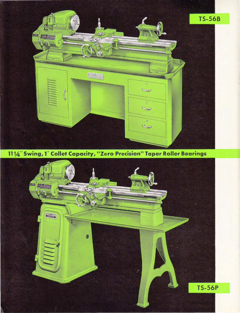
"Zero Precision" Tapered Roller Bearings
The Sheldon TS-56B is a modern precision machine tool, a product of intense engineering development, embodying the latest accepted advances in lathe design and quality tool construction features. It is specially designed to fulfill today's dual needs for a lathe that will operate efficiently both with standard tools at normal speeds and feeds and with the recently developed cutting materials and tools that require much extra power and speed. To insure extreme precision and the permanence of this accuracy, the spindle of the TS-56B is mounted in "Zero Precision" tapered Roller bearings-the most accurate obtainable. "Zero Precision" bearings are "specials" throughout their manufacture-are specially made and treated to exact size. These are bearings heretofore found only in the most costly machine tools. Here is accuracy never before given, nor even pretended, in a moderate priced lathe, accuracy unsurpassed at any price.
FEATURES "Zero Precision" Tapered Roller Bearings of size exceeding normal spindle load requirements.
Bed, cast in one piece, with two V ways and two flat ways ground to precision tolerances.
Drive is mounted underneath. Two B section V belts operate from drive to the spindle. Simple adjustment is provided for bel t tension.
Heavy headstock with solid bored bearing housing for tapered roller bearings.
Spindle hardened and ground.
Double walled apron with power cross feed.
Carriage has unusually large bearing surface and is accurately hand scraped and fitted to the bed ways.
Cross slide and compound rest have feed screws of a full one-half inch diameter, with milled threads.
Lead screw is 7/8" diameter milled on a precision thread miller to a tolerance of lead error of .0005" in any one inch.
Tailstock hand scraped to the ways and accurately aligned to headstock.
Thread chasing dial is standard equipment.
Steel bench has a solid steel plate top which acts as a chip pan, rigidly supported on a heavy fabricated base.
T 5-5 6 P This is the same lathe with the same specifications as the TS56B above, except that it is mounted on a pedestal
base. The chip pan and motor are extra.
"E" Type, Underneath Motor Drive
Double countershaft permits operation through standard one-piece lathe bed. Double V-belts to spindle prevent slippage, deliver full power. Four step cones give wide speed range. Lever release for belt shifting. Adjustable take-up for all belts.
SHELDON PRECISION LATHES 1 1 V4" Swing and 1" Collet Capacity
SPECI FICATIONS
CAPACITY AND CLEARANCES
Swing over bed .................... . Swing over cross slide .......... . Distance between centers ........... . Carriage length. . . .......... . Carriage bridge width .............. . Bed lengths. . . . . . . . . . . . . . . . . . ..... . Bed width ........................ . Bed height. . . . ......... .
THREADS AND FEEDS
II" Lathes
11�" 8"
35" 13" 4Yz"
56" 8" 7%"
Thread pitches available. . . . . . . . . . . . . 54 Screw threads per inch. . . . . . 4, 4 Yz, 5, 5 Yz,
5 %, 6, 6 Yz, 6 %, 7, 8, 9, 10, 11, 11 Yz, 12, 13, 13 Yz, 14, 16, 18, 20, 22, 23, 24, 26, 27, 28, 32, 36, 40, 44, 46, 48, 52, 54, 56, 64, 72, 80, 88, 92, 96, 104, 108, 112, 128, 144, 160, 176, 184, 192, 208, 216, 224
Longitudinal feeds through friction clutches ......................... . 0009 to .0535
Cross feeds through friction clutch .... . 0008 to .049 Lead screw dia. and threads per inch .. Ys" x 8 T.P.I.
HEADSTOCK
Hole through spindle ............... . Maximum collet capacity-Bar type .. . Maximum collet capacity-spindle nose
type .......... . Front spindle bearing. . .. . .... .
Rear spindle bearing. . . . . . . . ....... .
1 %" I"
1 %" I. D. 2�"
O.D. 4,Ys" I.D. 2"
O.D. 3%" Headstock spindle taper-Morse. N.o. 5 Size of center-Morse taper. . . . . . No. 3 Spindle nose diameter and T.P.I. ..... 2�" x 8 T. P.I. Size of spindle "V" belts (2), B Section %" Large face plate diameter ........... II" Small dog plate diameter. . . . . . . . . . . . . 5 Ys"
SPINDLE SPEEDS "E" Type Underneath Motor Drive
RP.M. of spindle, open belt. . . . 280-482-788-1355
RP.M. of spindle, back gears engaged. 50-87-142-244
"U" Type Underneath Motor Drive
RP.M. of spindle, open belt. . .... 1200-840-375-250
RP.M. of spindle, back gears engaged 215-145-65-45
Headstock Motor Drive
RP.M. of spindle, open belt. . . . . . . . .. 280-423-730 RP.M. of spindle, back gears engaged. 47-70-119
COMPOUND REST
Cross slide will travel. . . . . . . . . . . . . . . . 7" Angular feed of cross slide..... . . . . . . . 2%"
TOOL POST
Size of opening for tool holder shank .. Size of cutter bit tool holder takes ....
TAILSTOCK
Size of Morse taper center .......... . Spindle travel . ........ . Spindle diameter ................... . Each graduation on tailstock advances
spindle .... Tailstock top will set over for taper
turning ......................... .
MOTOR
Y2" x 2" �"
No. 3 3Yz" 1Yi6"
I"
Horse power recommended... . . .. . . . . 1 H.P. RP.M. recommended ............... 1725 RP.M.
STANDARD EQUIPMENT INCLUDES
Necessary Belts Tool Post Complete Headstock Center Center Sleeve
Small Dog Plate Thread Chasing Dial Tailstock Center Necessary Wrenches
9


SHELDON 12" Tool Room Precision Lathes "Zero Precision" Tapered Roller Bearings
The long bed, the" U" drive, the" Zero Inspection" tapered roller bearings in the headstock, the 13" swing, make the 12" Sheldon lathe the choice of many shops. The important features are listed below. Model TU-1248P, illustrated, is equipped with the most versatile and most advanced underneath motor drive, the "U" type. This is a 4-speed (8 spindle speed) V-belt drive on which speed changes are made instantly by lever shift. The speed change levers are entirely outside the enclosing cabinet leg and operate through clutches so that all speed changes are made without the necessity of touching belts, pulleys or other moving parts. The ease, speed and safety with which speed changes can be made, make this lathe particularly adaptable for tool rooms, second operation production work, maintenance departments, schools, and to all work where frequent speed changes are required.
FEATURES "Zero Precision" Tapered Roller Bearings of size exceeding normal spindle load requirements.
Bed, cast in one piece, with two V ways and two flat ways ground to precision tolerances.
Drive is mounted underneath. Two B section V belts operate from drive to the spindle. Simple adjustment is provided for bel t tension.
Heavy headstock with solid bored bearing housing for tapered roller bearings.
Spindle hardened an� ground.
Doubled walled apron.
Carriage has unusually large bearing surface and is accurately hand scraped and fitted to the bed ways.
Cross slide and compound rest have feed screws of a full one-half inch diameter, with milled threads.
Lead screw is 1/8" diameter milled on a precision thread miller to a tolerance of lead error of .0005" in any one inch.
Tailstock is hand scraped to the ways and accurately aligned to headstock.
Thread chasing dial is standard equipment.
Steel bench has a solid steel plate top which acts as a chip pan, rigidly supported on a heavy fabricated base.
TU -1236 B railir; ������sd a:: :���cl b���h �����e
d���e
b��'
: This same 12" lathe can be supplied with an "E" drive as shown on page 7. Lathes illustrated and listed have quick-change gears and power feed.
Other sizes of lathes available (not illustrated)
Mounted on Steel Bench -"E" Drive TE-1236-B 56" Bed 36" Center Distance
Mounted on Pedestal Base- "U" Drive TU-1236- P 56" Bed 36" Center Distance
Mounted on Pedestal Base- "E" Drive TE-1236- P 56" Bed 36" Center Distance TE-1 248-P 70" Bed 48" Center Distance
"U" TYPE Underneath Motor Drive
Like the "E-Type" drive described on the previous page, the" U -Type" drives through a standard lathe bed with double spindle belts. It has the additional advantage of being lever operated -all speed changes are instantly made through clutches by two outside levers. Especially recommended for tool rooms, repair departments and schools where speed changes are frequent and safety imperative.
SHELDON PRECISION LATHES 13Va" Swing and 1" Collet Capacity
SPECIFICATIONS
CAPACITY AND CLEARANCES
Swing over bed ............ ...... .. . Swing over cross slide . . ....... . .
12" Lathes
1 3Ys" 9"
Distance between centers ........... . Carriage length .................... . Carriage bridge width ......... . Bed lengths. . ................. . Bed width ........................ .
35" or 48" 1 3"
4;.-2" 56" or 70"
8" Bed Height ................ . 7�"
THREADS AND FEEDS
Thread pitches available. . . . . . . . . . . . . 54 Screw threads per inch . . . . 4, 4;.-2, 5, 5;.-2,
5;li, 6, 6;.-2, 6�, 7, 8, 9, 10, 1 1 , 1 1;.-2, 1 2, 13, 1 3;.-2, l4, 1 6, 1 8, 20, 22, 23, 24, 26, 27, 28, 32, 36, 40, 44, 46, 48, 52, 54, 56, 64, 72, 80, 88, 92, 96, 104, 1 08, 1 12, 1 28, 144, 1 60, 1 76, 1 84, 192, 208, 216, 224
Longitudinal feeds through friction clutch. . . .................. . 0009 to .0535
Cross feeds through friction clutch .... . 0008 to .049 Lead screw dia. and threads per inch . . Ys" x 8 T. P. I.
HEADSTOCK
Hole through spindle ........... . Maximum collet capacity-Bar type .. Maximum collet capacity-Spindle nose
1%" I"
type ......... . Front spindle bearing ....... .
1 %" I.D. 2�"
O.D. 4Ys" Rear spindle bearing . I. D. 2"
O. D.3%" Headstock spindle taper-Morse. . . . . . No. 5 Size of center-Morse taper. . . No. 3 Spindle nose diameter and T. P.I. ..... 2�" x 8 T. P. I. Size of spindle "V" belts (2), B section. . %" Large face plate diameter. . . . . . . . . . . . 1 2" Small dog plate diameter.... . . . . . . ... 5Ys"
SPINDLE SPEEDS "En Type Underneath Motor Drive
RP. M. of spindle, open belt. ........ 280-482-788-1355
RP. M. of spindle, back gears engaged . 50-87-142-244
"U" Type Underneath Motor Drive
RP.M. of spindle, open belt . 1200-840-375-250
RP.M. of spindle, back gears engaged. 215-l45-65-45
Headstock Motor Drive
RP.M. of spindle, open belt... 280-423-730 RP. M. of spindle, back gears engaged. 47-70-119
COMPOUND REST
Cross slide will travel. Angular feed of cross slide .....
TOOL POST
7" 3;.-2"
Size of opening for tool holder shank. Size of cutter bit tool holder takes ..
%" x 2;.-2" %"
TAILSTOCK
Size of Morse taper center .......... . Spindle travel . ....... . Spindle diameter ................... . Each graduation on tailstock advances
spindle ........................ . Tailstock top will set over for taper
turning. . .. . ....... . ...... .
MOTOR
I"
Horsepower recommended ........... . R. P.M. recommended.
1 H.P. 1725 RP. M.
STANDARD EQUIPMENT INCLUDES-
Necessary Belts Small Dog Plate Tool Post Complete Thread Chasing Dial Headstock Center Tailstock Center Center Sleeve Necessary Wrenches
11
12
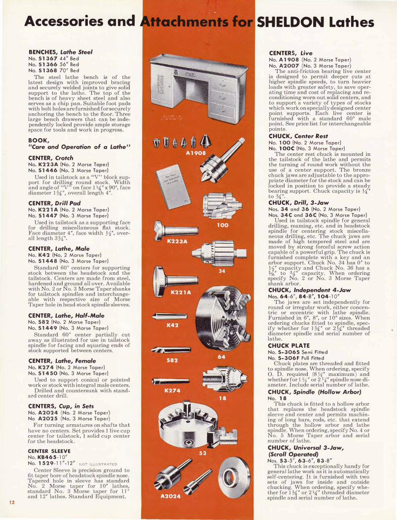
Accessories and
BENCHES, Lathe Steel No.5 1367 44/1 Bed No. 51 366 56/1 Bed No. 5 1368 70" Bed
The steel lathe bench is of the latest design with improved bracing and securely welded joints to give solid support to the lathe. The top of the bench is of heavy sheet steel and also serves as a chip pan. Suitable foot pads with bolt holes are furnished for securely anchoring the bench to the floor. Three large bench drawers that can be independently locked provide ample storage space for tools and work in progress.
BOOK, "Care and Operation of a Lathe"
CENTER, Crotch No. K223A (No.2 Mor se Toper) No. 51446 (No.3 Mor se Taper )
Used in tailstock as a "V" block support for drilling round stock. Width and angle of "V" on face l)4" x 90°, face diameter 1%;/1, overall length 4".
CENTER, Drill Pad No. K221 A (No.2 Morse Taper ) No.5 1447 (No.3 Mor se Taper )
Used in tailstock as a supporting face for drilling miscellaneous flat stock. Face diameter 4", face width Y2", overall length 3%;".
CENTER, Lathe, Male No. K42 (No.2 Mor se Taper ) No. 51448 (No.3 Mor se Taper )
Standard 60° centers for supporting stock between the headstock and the tailstock. Centers are made from steel, hardened and ground all over. Available with No. 2 or No.3 Morse Taper shanks for tailstock spindles and interchangeable with respective size of Morse Taper hole in head stock spindle sleeves.
CENTER, Lathe, Half-Male No. 582 (No.2 Mor se Taper ) No. 51449 (No.3 Mor se Taper )
Standard 60° center partially cut away as illustrated for use in tailstock spindle for facing and squaring ends of stock supported between centers.
CENTER, Lathe, Female No. K274 (No.2 Mor se Taper) No. 51450 (No.3 Mor se Taper )
Used to support conical or pointed work or stock with integral male centers.
Drilled and countersunk with standard center drilL
CENTERS, Cup, in Sets No. A2024 (No.2 Mor se Taper ) No A2025 (No.3 Mor se Taper )
For turning armatures on shafts that have no centers. Set provides 1 live cup center for tailstock, 1 solid cup center for the headstock.
CENTER 5LEEVE No. KB465-1 0" No. 1529·11/1·12/1 NOT ILLUSTRATED
Center Sleeve is precision ground to fit taper bore of headstock spindle nose. Tapered hole in sleeve has standard No. 2 Morse taper for 10" lathes, standard No. 3 Morse taper for 11" and 12" lathes. Standard Equipment.
SHELDON Lathes
CENTERS, Live No. A 1908 (No.2 Mor se Taper ) No. A2007 (No.3 Mor se Taper )
The anti-friction bearing live center is designed to permit deeper cuts at higher spindle speeds, to turn heavier loads with greater safety, to save operating time and cost of replacing and reconditioning worn out solid centers, and to support a variety of types of stocks which work on specially designed center point supports. Each live center is furnished with a standard 60° male point. See price list for interchangeable points.
CHUCK, Center Rest No. 100 (No.2 Mor se Taper ) No.100C (No.3 Mor se Taper )
The center rest chuck is mounted in the tail stock of the lathe and permits the turning of round work without the use of a center support. The bronze chuck jaws are adjustable to the appropriate diameter for the stock and can be locked in position to provide a steady bearing support. Chuck capacity is )4" to %;". CHUCK, Drill, 3-Jaw Nos. 34 and 36 (No.2 Mor se Taper ) Nos. 34C and 36C (No.3 Mor se Taper )
Used in tailstock spindle for general drilling, reaming, etc. and in headstock spindle for centering stock miscellaneous drilling, etc. The chuck jaws are made of high tempered steel and are moved by strong forceful screw action capable of a powerful grip. The chuck is furnished complete with a key and an arbor support. Chuck No. 34 has 0" to Y2" capacity and Chuck No. 36 has a %" to <J.i" capacity. When ordering specify No. 2 or No. 3 Morse Taper shank arbor. CHUCK, Independent 4-Jaw Nos. 64-6/1 , 84-8/1, 104-10/1
The jaws are set independently for round or irregular work, either concentric or eccentric with lathe spindle. Furnished in 6", 8", or 10" sizes. When ordering chucks fitted to spindle, specify whether for 1%;" or 2)4" threaded diameter spindle and serial number of lathe.
CHUCK PLATE No. 5-3065 Semi Fi t ted No. 5-306F Full Fi t ted
Chuck plates are threaded and fitted to spindle nose. When ordering, specify O. D. required (8)4" maximum ) and whether for 1 %;/1 or 2)4" spindle nose diameter. Include serial number of lathe.
CHUCK, Spindle (Hollow Arbor) No. 18
This chuck is fitted to a hollow arbor that replaces the headstock spindle sleeve and center and permits machining of long bars, rods, etc. that extend through the hollow arbor and lathe spindle. When ordering, specify No.4 or No. 5 Morse Taper arbor and serial number of lathe.
CHUCK, Universal 3-Jaw, (Scroll Operated) Nos. 53-5/1,63-6/1,83-8/1
This chuck is exceptionally handy for general lathe work as it is automatically self-centering. It is furnished with two sets of jaws for inside and outside chucking. When ordering, specify whether for 1%;" or 2)4" threaded diameter spindle and serial number of lathe.

Accessories and
COLLET CHUCK ATTACHMENT, Handwheel Draw-In Type No. XL462A-l0" (1" Colle t Cop. ) No. 5M462A-ll" -12" (1" Colle t Cop.)
The standard handwheel type drawin collet attachment is useful for general precision work on a variety of sizes of standard bar stock. The complete attachment includes the hollow draw bar with hand wheel, hardened and ground collet adaptor sleeve, thrust bearing, spacer sleeve, spindle nose cap and spanner wrench. The attachment is available for 1" collet capacity lathes (5-C collets ). When ordering, specify serial number of lathe.
COLLET CHUCK ATTACHMENT, Handlever Draw-In Type No. XL462 H-l 0" (1" Collet Cap. ) No. 5M462H-ll" -12" (1" Colle t Cap. )
The standard handlever type draw-in collet attachment is very useful for rapid repetitive manufacture of duplicate parts from standard bar stock or rod, eliminating the necessity of stopping the lathe to feed the bar stock or rod through the collet. By regulating the main body sleeve of the adjustable chuck closer, the holding force of the collet may be set to any degree of re sistance. The complete attachment includes the lever attachment, hollow draw bar, hardened and ground collet adaptor sleeve, spindle nose cap and spanner wrench. The attachment is available for 1" collet capacity lathes (5-C collets.) When ordering, specify serial number of lathe.
COLLET CHUCK ATTACHMENT, Spindle Nose Type, Handlever No. A2021-1 0" -11 " _12" (1 Y2" Colle t
Cap. ) (1 :Ya" hole through the spindle ) SEE ILLUSTRATION NO. A2020
The lever operated collet chuck attachment can be operated without stopping the spindle. The positive lock of the closing collar holds the work firmly in position while in operation.
Uses Collets A2123, A2124, A2125.
COLLET CHUCK ATTACHMENT,
Spindle Nose Type, Handwheel No. A211 5-10" -11" _12" (1 :Ya" Collet
Capa city)
Not illustrated; replaces A2022.
Spindle nose type collet chuck at-tachment permits use of collets up to full capacity of spindle. Quick turn of handwheel automatically opens or closes the collet.
Collets for the spindle nose chuck are of a special type. Chuck number must be specified when ordering. Please include serial number of lathe with order.
Uses Collets 2JR, 2JS, 2JH.
COLLET RACK, Metal No. KB647-5-10" -11" -12"
SEE ILLUSTRATION NO. KB647-4
This collet rack provides a convenient holder for collets, lathe centers and spindle sleeve. The rack is easily mounted on the back way of any lathe bed. Space is provided for 16-5C collets, 2 centers and one spindle sleeve.
ELDON Lathes
COLLET RACK, Wood (Drawer) No. 536-11" -12"
This liner unit placed in a drawer of the steel bench provides a clean and handy holder for 16-5C collets, draw-bar for draw-in collet attachment, collet adaptor sleeve, spindle nose cap, spindle center sleeve, spanner wrenches, headstock and tailstock centers and tool post.
COLLETS, (Standard) Round Square Hexagon
Standard collets for use with standard handwheel or handlever type collet attachments are available in model 4-C for the �" collet capacity lathe and in model 5-C for the 1" collet capacity lathe. The collets are very accurately made from high grade tool steel hardened and ground inside and outside. When ordering collet, specify Model and specific size desired. Special decimal or metric size round, square, hexagon or step collets can also be furnished with prices on request_
DOGS, BENT TAIL, Drop Forged
Improved design, finest quality, drop forged from special open hearth steel, heat treated to extreme toughness with alloy steel screws. When ordering, specify if "Square Head" or "Headless" screws are desired. (See price list for stock numbers.)
DOGS, CLAMP TYPE, Drop Forged Nos. 11 a nd 12
As a clamp or lathe dog, the drop forged steel clamp dog, properly heattreated, securely grips a variety of shapes of stock. Construction of upper bar allows for considerable tilting without bending screws_
GRINDERS, Tool Post No. 14-1/4 h.p., No. 11-1/5 h.p. , No. 44-1 /4 h.p. , No. 18-011-1/4 h.p.
No. 14 for Sheldon 1 0" and 1 1 " lathes for light duty precision work -two speeds, 10,000 or 22,500 r.p.m.
No. 11 or 44 for all size lathes; for precision external and internal work, with speeds of 6,000 to 38,000 r.p.m.
No. 1 8-01 1 Utility grinder for all size lathes for precision external grinding-5,000 r.p.m.
LAMP, LATHE, Adjustable No. A1909
This all metal lathe lamp was selected for its light centering efficiency, and its adjustable flexible shaft provides for best light coverage. Back of shade and entire arm have non-reflecting surface. Lamp bolts to back of lathe bed and is removable. Comes complete with cord and plug.
METRIC TRANSPOSING ATTACHMENT
The metric transposing attachment consists of a compound gear and six standard change gears. The attachment provides means for cutting 33 standard threads from .020 to 6.0 mm. pitch. For complete information, ask for bulletin No. 101851 .
13

Accessories and
MILLING and KEYWAY CUTTING ATTACHMENT Nos. L411 A-10/1, K411 A-ll/1, M411A-12/1
A handy and economical attachment that is ideal for small shops not having enough work for a regular milling machine or to relieve the regular milling machine when additional facilities are needed. The attachment is mounted on the lathe saddle and is capable of swiveling 360° in the horizontal plane and 90° either side of the center in the vertical plane and is graduated 180 degrees. The vertical travel of the slide is 3/1 and the vertical adjusting screw is furnished with a micrometer graduated collar. Width of vise jaws 372", depth of jaws 1Ys", opening of vise jaws with %" x 90° V-way jaw plate in position 1", without screw plates 1 %". Maximum distance from center of lathe spindle to face of bottom jaw at bottom of travel 1 %". When ordering, specify size and serial number of lathe.
MILLING ARBOR, lor Milling and Keyway Cutting Attachment No.5M352-10/l-11/1-12/1
sEE ILLUSTRATION NO. KM352
1" arbor accurately machined, hardened and ground. Has two 72" spacers and 7<1:" spacer. Capacity (between shoulder and tightening nut) 1%". When ordering, specify No. 5 Morse Taper shank for 1" collet capacity lathes.
MOTORS
Motors are not included in the list price of Sheldon machine tools, but can be supplied at extra cost. We supply standard frame, ball bearing, 1800 R P M reversing motors made by dependable electric motor manufacturers.
Stock motors are A.C., 110/220 Volt, 60 cycle, 1 phase, or 220/440 volt, 50/60 cycle, 3 phase; also some odd voltage and D.C. motors. Special motors are available.
Motors ordered with the machine are fitted and wired at the factory at no additional cost. Motors shipped to the factory by the customer or dealer will be fitted and wired at a flat additional price, regardless of size or type.
Be sure to give complete motor voltage, phase, and cycle requirements when placing orders for machines. Use recommended horsepower ratings as indicated on the catalog pages and price sheet.
PANS, Oil and Chip Oil and chip pans are made of heavy
gauge sheet steel with rolled rim and welded corners and will serve as both chip pan and oil reservoir for coolant pump. Pans are available for underneath motor driven lathes and should be ordered with the lathe to permit fitting at the factory. When ordering pans for lathes already in service, specify model and serial number of lathe. One pan leg and one new floor leg must be ordered with chip pan for all underneath motor driven pedestal base floor model lathes. Two pan legs and two new floor legs must be ordered with chip pans for all headstock mounted motor driven floor leg model lathes. No credit allowed for old floor legs.
14
SHELDON Lathes
PISTON TURNING FIXTURE No. 5134610/1-11/1-12"
SEE ILLUSTRATION NO. LI346
A very convenient self chucking attachment for turning pistons 272" to 4" O.D. The unit consists of two cone rings, one flat centering ring, one arbor, and a large and small driving dog. When ordering, specify size and serial number of lathe. Tapered arbor fits in spindle nose.
PLATE, DOG LTKT 182 5lfs/l Diame ter
Small semi-steel face plate designed to drive lathe dog when supporting work between centers. Has two clamp slots and two aligned holes. Accurately machined and threaded to fit lathe spindle nose thread. When ordering, specify whether for 1 %" or 2 7<1:" threaded diameter spindle and serial number ot lathe.
PLATE, FACE, Large Size No. XL 1546-10" No. LT183-11 " , No. KT185-12"
Large face plate for supporting and revolving flat stock, or clamped on jigs or fixtures used for miscellaneous machining operations. These face plates are made of semi-steel with ribbed reinforced back, have eight clamp slots and are accurately threaded to fit the lathe spindle nose. When ordering, specify if 10", 11", or 12" diameter plate is desired and give the serial number of your lathe.
PLATE, HANDWHEEL No. 5182-11", No. M182-12"
7*/1 Diame ter Accurately machined combination dog
and face plate with 4 indexed clamp slots with smoothly rounded rim to permit use as an inching wheel. Threaded for 27<1:" spindle nose. Specify serial number of lathe when ordering.
PUMP, COOLANT, Portable No. A2079-1 110 Yolt, I- phase No. A2079-3 220 Yolt, 3- phase
SEE ILLUSTRATIONS NOS. A 1906 AND A 1907
Light in weight, compact in design but still ample in capacity, this efficient coolant or cutting oil circulating system is recommended for lathes set up for production. Its motor operated pump is of positive pressure, curved fin type with a ventur inlet on the return side of the impeller, which assures the uniformity of flow (hydraulic efficiency as high as 70 %) with minimum wear. Pump is furnished with necessary pipe and fittings.
Other voltages available.
REST, FOLLOWER, 2-Jaw Nos. L209A-l 0/1, K209A-ll/1 , M209A-12/1
The follower rest is attached to and moves with the lathe carriage saddle and supports long flexible and slender shafts in proper position to the cutting tool during miscellaneous machining operations to assure accurate results. The machined adjustable jaws can be set by adjustable screws and locked in place for any desired diameter of bar stock within the range of %;" to 372" capacity. When ordering, specify size and serial number of lathe.

Accessories and
REST, STEADY, (Center) Hinged Type Nos. L575A-1 0/1, K575A-11/1, M575A-12/1
SEE ILLUSTRATION NO. L576A
The steady rest is mounted at any desirable place on the bed locating on one "V" way and one flat way and is used to support long, flexible shafts, rods and tubes for various machining operations such as turning, �oring, threading, etc. The steady rest IS furnished with three quickly adjustable machined jaws that can be set by adjustable screws and locked in position for any desired diameter of stock within the range of %;/1 to 372/1 capacity. The top of the steady rest is hinged to facilitate quick and easy insert�on and �emoval of stock. When ordermg, specIfy size and serial number of lathe.
REST SET, Wood Turning L281A-10/l, K281A-11/1, M281A-12/1
This hand rest for wood turning consists of a convenient base that slides into the tool post T-slot, and one each 4/1 and 8/1 interchangeable T-rests.
STOP, CARRIAGE, Plain No. K908A An efficient, inexpensive carriage stop
that clamps to the lathe bed locating one "V" way at any point, and that serves to indicate the stopping point on facing, boring operations, etc.
STOP, CARRIAGE, Micrometer No. K693A
A precision stop with micrometer screw adjustment that clamps on the bed, locating on one "V" way at any point. A thumb nut locks the screw at any desired setting with a 1/1 screw travel either way.
STOP, THREAD-CUTTING, Adiustab'e No. K870A
Can be assembled to lathe carriage to regulate pre-determined depth of cut for turning or cutting screw threads.
SWITCHES, REVERSING Nos. R22 (l- phose), R44 (3- phase)
The starter switch is of the lever operated drum reversing type, having "forward," "off" and "reverse" positions. When ordering, specify if for single or three phase operation.
Direct current reversing switches are also available at prices given upon request. When ordering, give complete D.C. motor specifications.
TAILSTOCK, LEVER OPERATED Nos. L72H-1 0/1, K72H-11/1, M72H-12/1
The handlever operated tailstock is primarily a production accessory designed for production, drilling, reaming, etc. Either the handlever or handwheel of this tailstock can be used. The tailstock spindle has a 2%/1 travel.
TAPER ATTACHMENTS, Plain Nos. LT210A-l 0/1, KT21OA-11/1, MT210A-12/1
Taper attachments are an important unit for use on lathes in taper turning and boring long tapers or where repetitive duplicate taper turning or boring is necessary. Accurate performance is obtained through simplicity of design and sturdy construction.
The plain taper attachment can be easily assembled and fitted to any Sheldon lathe carriage. The swivel bar is graduated in inches per foot on one end and in degrees on the other end
ELDON Lathes
and permits turning or boring tapers up to 3" per foot, 772" in length at any one setting.
TAPER ATTACHMENT, Telescopic Nos. LTT21 OA-1 0/1, KTT21 OA-11/1, MTT210A-12/1
The new telescopic taper attachment can also be assembled and fitted to any Sheldon lathe carriage and is furnished with a telescopic cross feed screw that eliminates the necessity of disengaging the cross feed screw nut as in the case of the plain taper attachment. This attachment has tapered gibs for adjusting the slide saddle for quick and even adjustment. The swivel bar is similar to the plain taper attachment, being graduated in inches per foot in one end and in degrees on the other end. Tapers up to 372" per foot and 972/1 in length may be turned or bored at any one setting.
THREAD CHASING DIAL No. K890A
Ends need for reversing lathe when cutting threads. All even threads start on any dial graduation. Odd threads start on any numbered graduation. Half threads start on odd number graduations.
TOOL HOLDERS Tool holders are permanent, multi
purpose tools. With a few cutters quickly ground from standard shapes of high speed steel, each tool holder effe�tively equals a complete set of sohd tools. Embodying years of design refinement, each assures maximum efficiency at all speeds and feeds and will give many years of economical service. (See price list for stock numbers.)
TOOL POST (Double) Lever Operated L664A-10/1, K664A-11/1, M664A-12/1
The Double Tool Post attachment provides a two way, front and back tool post operation that cuts job time in half. Available with either handlever or hand wheel screw action with adjustable stops for both front and back tools. Recommended for forming, rounding, knurling, cutting off, etc., of duplicate parts. Please give serial number of lathe when ordering.
TOOL POST, TURRET, J2 Position A 1967 _10/1, A 1968-11/1, A 1969-12/1
This all-steel 4-tool turret tool post production accessory with hardened alloy steel headless screws fits into the tool post T -slot of the compound rest. It has 12 indexing positions (3 working positions for each tool). Holds standard square or rectangular bits, boring bars and cut-off blades.
TURRET, BED, Handwheel A1970-10/l, A1971-11/1 A1972-12/1
Designed for rapid and accurate machining of duplicate parts, including such operations as turning, drilling, reaming, counterboring, threading, knurling, etc. The turret head automatically registers one-sixth of a turn with each back movement of the hand lever. Length of tool operations regulated by adjustable stops provided for each of the six indexed positions of the turret head. Suitable take-up gibs assure lasting accuracy. Turret takes standard diameter shank screw machine tools. Capacities-4,!i" or 672" stroke.
15
TELEPHONES
WALTER H. MEYER MACHR'Y CO.
FORT WAYNE, INDIANA