Bid Addendum - ArDOT Ads/Bid 13-58, … · bridge, storm drainage installation, retaining walls,...
88
City of Fayetteville, Arkansas Bid 13‐58, Addendum 1 Page 1 of 2 (not including attachments) Bid 13 ‐ 58, Addendum 1 Date: Wednesday, January 8, 2014 To: All Prospective Vendors From: Andrea Foren, CPPO, CPPB – 479.575.8220 – aforen@fayetteville‐ar.gov RE: Bid 13‐58, Construction, Town Branch Trail – School to Greathouse Park NOTICE TO BIDDERS: This Addendum shall be a part of the Plans, Contract Documents and Specifications to the same extent as though it were originally included therein, and it shall supersede anything contained in the Plans, Contract Documents and Specifications with which it might conflict. Bidders should indicate their receipt of addendum in the appropriate blank of the Bid Form. Failure to do so may subject bidder to disqualification. This addendum should be included, completed, and submitted with bid. *** THIS ADDENDUM CONTAINS A REVISED BID FORM THAT SHALL BE USED BY ALL BIDDERS. FAILURE TO USE THE CORRECT BID FORM WILL RESULT IN BID REJECTION. *** 1. Bid Check List ‐ Section 00020 is revised and replaced with the included revised section (Revised) – The Disadvantaged Business Enterprise (DBE) requirements have been removed from the check list. This contract does not have a Disadvantaged Business Enterprise (DBE) Goal; however, DBE outreach is encouraged. 2. Agreement Form ‐ Section 00500 is revised and replaced with the included section (Revised) ‐ Project time changed to 150 days for substantial completion, 180 for final Completion. 3. Bid Form ‐ Section 00410 is revised and replaced with the included section (Revised) ‐ Bid Item 11 – shall be 8’ Wide by 3’ High Box Culvert and special provision references updated. a) ALL BIDDERS SHALL USE THE REVISED ATTACHED BID FORM INCLUDED WITH THIS ADDENDUM. FAILURE TO USE THE CORRECT BID FORM WILL RESULT IN BID REJECTION. 4. SP‐3 is revised and replaced with the included section (Revised) – Excel Bridge included as a pre‐ approved bridge manufactures. 5. SP‐3‐3.1 ‐ Bridge is specified as “Bowstring”, a modified bowstring is shown on sheet S4 for graphical purposes only. 6. SP‐12‐3 is revised and replaced with the included section (Revised) ‐ Electric Service Panel shall be provided based on specification included under SP 12‐3 section 2.3 H.
Transcript of Bid Addendum - ArDOT Ads/Bid 13-58, … · bridge, storm drainage installation, retaining walls,...

City of Fayetteville, Arkansas Bid 13‐58, Addendum 1 Page 1 of 2 (not including attachments)
Bid 13‐58, Addendum 1
Date: Wednesday, January 8, 2014
To: All Prospective Vendors
From: Andrea Foren, CPPO, CPPB – 479.575.8220 – aforen@fayetteville‐ar.gov
RE: Bid 13‐58, Construction, Town Branch Trail – School to Greathouse Park
NOTICE TO BIDDERS: This Addendum shall be a part of the Plans, Contract Documents and Specifications to the same extent as though it were originally included therein, and it shall supersede anything contained in the Plans, Contract Documents and Specifications with which it might conflict. Bidders should indicate their receipt of addendum in the appropriate blank of the Bid Form. Failure to do so may subject bidder to disqualification. This addendum should be included, completed, and submitted with bid. *** THIS ADDENDUM CONTAINS A REVISED BID FORM THAT SHALL BE USED BY ALL BIDDERS. FAILURE TO
USE THE CORRECT BID FORM WILL RESULT IN BID REJECTION. ***
1. Bid Check List ‐ Section 00020 is revised and replaced with the included revised section (Revised) – The
Disadvantaged Business Enterprise (DBE) requirements have been removed from the check list. This contract does not have a Disadvantaged Business Enterprise (DBE) Goal; however, DBE outreach is encouraged.
2. Agreement Form ‐ Section 00500 is revised and replaced with the included section (Revised) ‐ Project time changed to 150 days for substantial completion, 180 for final Completion.
3. Bid Form ‐ Section 00410 is revised and replaced with the included section (Revised) ‐ Bid Item 11 –
shall be 8’ Wide by 3’ High Box Culvert and special provision references updated.
a) ALL BIDDERS SHALL USE THE REVISED ATTACHED BID FORM INCLUDED WITH THIS ADDENDUM. FAILURE TO USE THE CORRECT BID FORM WILL RESULT IN BID REJECTION.
4. SP‐3 is revised and replaced with the included section (Revised) – Excel Bridge included as a pre‐
approved bridge manufactures.
5. SP‐3‐3.1 ‐ Bridge is specified as “Bowstring”, a modified bowstring is shown on sheet S4 for graphical purposes only.
6. SP‐12‐3 is revised and replaced with the included section (Revised) ‐ Electric Service Panel shall be provided based on specification included under SP 12‐3 section 2.3 H.
City of Fayetteville, Arkansas Bid 13‐58, Addendum 1 Page 2 of 2 (not including attachments)
7. SP‐16 (Added) – A micro pile foundation system will be allowed for the bridge foundation as an alternative to “H” Piles according to the requirements of this Special Provision.
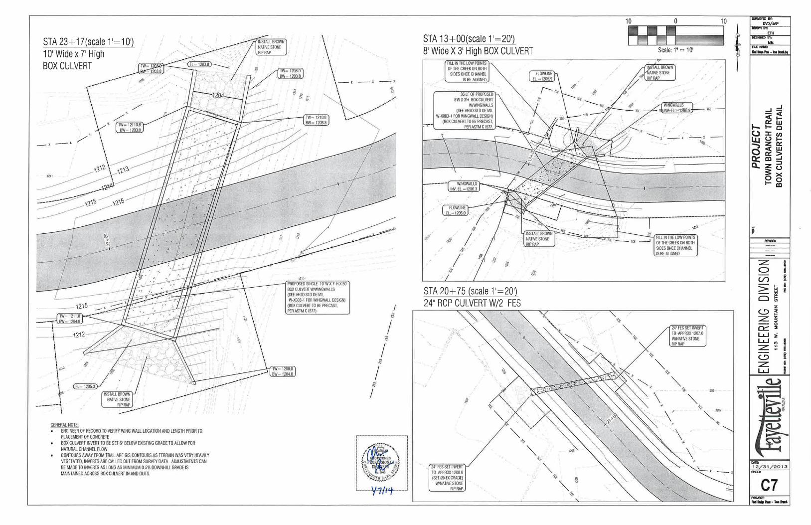
8. Sheet C7 is revised and replaced with the included section (Revised) – Revised to show 7’ High by 10’
Wide Box Culvert (single cell only).
9. Reference Sheet S2 – The connection from the bridge approach slab to the existing concrete trail is not necessary as the existing concrete trail will be removed as shown on Sheet C3.
10. Sheet S8 and SP‐5 are revised and replaced with the included sections (Revised) – The Modular Block Alternate shown on S8 and SP‐5 is removed. Contractor shall bid the cast in place wall as shown on sheet S7 and specified in the revised SP‐5 included.
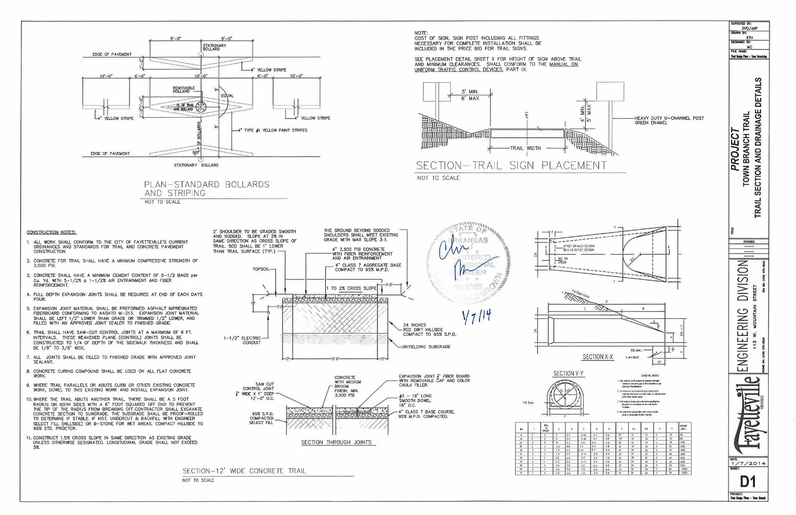
11. Sheet D1 is revised and replaced with the included section (Revised) – to show expansion joint only required at the end of each day’s pour.
12. Awarded contractor shall not be responsible for providing any stamped design drawings. This does not apply to shop drawings.
13. The following documents are hereby made attachments to this addendum and replace the original sections contained in the bid package and drawings:
a) Table of Contents – Section 00010 b) Bid Check List – Section 00020 c) Invitation to Bid – Section 00120 d) Instructions to Bidders – Section 00200 e) Bid Form – Section 00400 ‐ (CONTRACTOR SHALL COMPLETE AND SUBMIT THIS REVISED BID
FORM) f) Agreement Form – Section 00500 g) Bonds and Insurance – Section 00600 h) SP‐3 i) SP‐5 j) SP‐12 k) SP‐16 (New) l) Sheet C7, revised version dated 01/07/2014 m) Sheet D1, revised version dated 01/07/2014
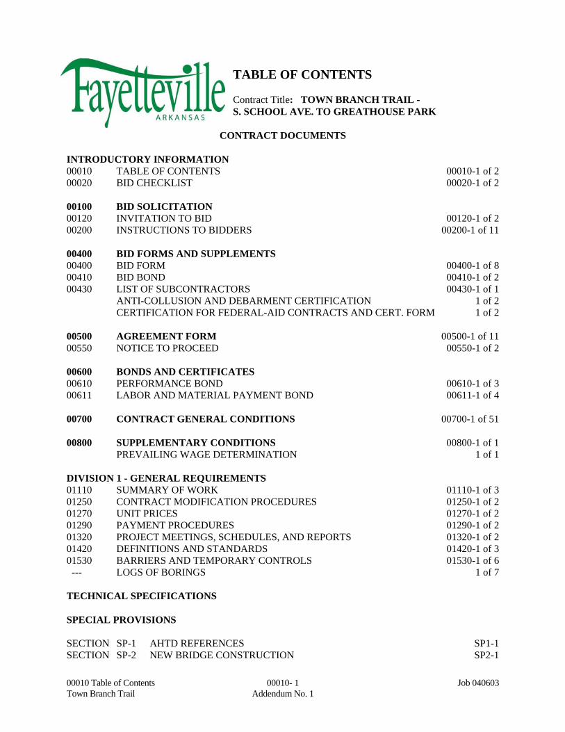
00010 Table of Contents 00010- 1 Job 040603 Town Branch Trail Addendum No. 1
TABLE OF CONTENTS Contract Title: TOWN BRANCH TRAIL - S. SCHOOL AVE. TO GREATHOUSE PARK
CONTRACT DOCUMENTS INTRODUCTORY INFORMATION 00010 TABLE OF CONTENTS 00010-1 of 2 00020 BID CHECKLIST 00020-1 of 2 00100 BID SOLICITATION 00120 INVITATION TO BID 00120-1 of 2 00200 INSTRUCTIONS TO BIDDERS 00200-1 of 11 00400 BID FORMS AND SUPPLEMENTS 00400 BID FORM 00400-1 of 8 00410 BID BOND 00410-1 of 2 00430 LIST OF SUBCONTRACTORS 00430-1 of 1 ANTI-COLLUSION AND DEBARMENT CERTIFICATION 1 of 2 CERTIFICATION FOR FEDERAL-AID CONTRACTS AND CERT. FORM 1 of 2 00500 AGREEMENT FORM 00500-1 of 11 00550 NOTICE TO PROCEED 00550-1 of 2 00600 BONDS AND CERTIFICATES 00610 PERFORMANCE BOND 00610-1 of 3 00611 LABOR AND MATERIAL PAYMENT BOND 00611-1 of 4 00700 CONTRACT GENERAL CONDITIONS 00700-1 of 51 00800 SUPPLEMENTARY CONDITIONS 00800-1 of 1 PREVAILING WAGE DETERMINATION 1 of 1 DIVISION 1 - GENERAL REQUIREMENTS 01110 SUMMARY OF WORK 01110-1 of 3 01250 CONTRACT MODIFICATION PROCEDURES 01250-1 of 2 01270 UNIT PRICES 01270-1 of 2 01290 PAYMENT PROCEDURES 01290-1 of 2 01320 PROJECT MEETINGS, SCHEDULES, AND REPORTS 01320-1 of 2 01420 DEFINITIONS AND STANDARDS 01420-1 of 3 01530 BARRIERS AND TEMPORARY CONTROLS 01530-1 of 6 --- LOGS OF BORINGS 1 of 7 TECHNICAL SPECIFICATIONS
SPECIAL PROVISIONS SECTION SP-1 AHTD REFERENCES SP1-1 SECTION SP-2 NEW BRIDGE CONSTRUCTION SP2-1
00010 Table of Contents 00010- 2 Job 040603 Town Branch Trail Addendum No. 1
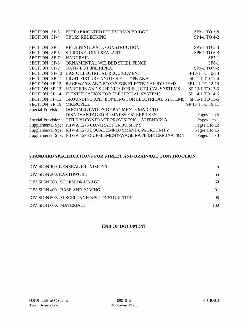
SECTION SP-3 PREFABRICATED PEDESTRIAN BRIDGE SP3-1 TO 3-8 SECTION SP-4 TRUSS REDECKING SP4-1 TO 4-2 SECTION SP-5 RETAINING WALL CONSTRUCTION SP5-1 TO 5-3 SECTION SP-6 SILICONE JOINT SEALANT SP6-1 TO 6-3 SECTION SP-7 HANDRAIL SP7-1 SECTION SP-8 ORNAMENTAL WELDED STEEL FENCE SP8-1 SECTION SP-9 NATIVE STONE RIPRAP SP9-1 TO 9-2 SECTION SP-10 BASIC ELECTRICAL REQUIREMENTS SP10-1 TO 10-13 SECTION SP-11 LIGHT FIXTURE AND POLE – TYPE A&B SP11-1 TO 11-4 SECTION SP-12 RACEWAYS AND BOXES FOR ELECTRICAL SYSTEMS SP12-1 TO 12-13 SECTION SP-13 HANGERS AND SUPPORTS FOR ELECTRICAL SYSTEMS SP 13-1 TO 13-5 SECTION SP-14 IDENTIFICATION FOR ELECTRICAL SYSTEMS SP 14-1 TO 14-6 SECTION SP-15 GROUNDING AND BONDING FOR ELECTRICAL SYSTEMS SP15-1 TO 15-5 SECTION SP-16 MICROPILE SP 16-1 TO 16-11 Special Provision DOCUMENTATION OF PAYMENTS MADE TO DISADVANTAGED BUSINESS ENTERPRISES Pages 1 to 5 Special Provision TITLE VI CONTRACT PROVISIONS – APPENDIX A Pages 1 to 1 Supplemental Spec. FHWA 1273 CONTRACT PROVISIONS Pages 1 to 12 Supplemental Spec. FHWA 1273 EQUAL EMPLOYMENT OPPORTUNITY Pages 1 to 15 Supplemental Spec. FHWA 1273 SUPPLEMENT-WAGE RATE DETERMINATION Pages 1 to 3 STANDARD SPECIFICATIONS FOR STREET AND DRAINAGE CONSTRUCTION DIVISION 100. GENERAL PROVISIONS 5
DIVISION 200. EARTHWORK 55
DIVISION 300. STORM DRAINAGE 68
DIVISION 400. BASE AND PAVING 81
DIVISION 500. MISCELLANEOUS CONSTRUCTION 96
DIVISION 600. MATERIALS 130
END OF DOCUMENT
00020 Page 1 of 2 Addendum No. 1
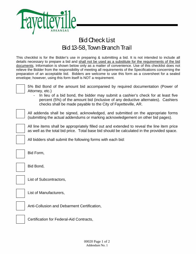
Bid Check List Bid 13-58, Town Branch Trail
This checklist is for the Bidder’s use in preparing & submitting a bid. It is not intended to include all details necessary to prepare a bid and shall not be used as a substitute for the requirements of the bid documents. Information is shown below only as a matter of convenience. Use of this checklist does not relieve the Bidder from the responsibility of meeting all requirements of the Specifications concerning the preparation of an acceptable bid. Bidders are welcome to use this form as a coversheet for a sealed envelope; however, using this form itself is NOT a requirement.
o 5% Bid Bond of the amount bid accompanied by required documentation (Power of Attorney, etc.)
- In lieu of a bid bond, the bidder may submit a cashier’s check for at least five percent (5%) of the amount bid (inclusive of any deductive alternates). Cashiers checks shall be made payable to the City of Fayetteville, AR.
o All addenda shall be signed, acknowledged, and submitted on the appropriate forms
(submitting the actual addendums or marking acknowledgement on other bid pages). o All line items shall be appropriately filled out and extended to reveal the line item price
as well as the total bid price. Total base bid should be calculated in the provided space. o All bidders shall submit the following forms with each bid: Bid Form, Bid Bond, List of Subcontractors, List of Manufacturers, Anti-Collusion and Debarment Certification, Certification for Federal-Aid Contracts,

00020 Page 2 of 2 Addendum No. 1
Bid Check List Bid 13-58, TOWN BRANCH TRAIL
(continued)
o All pages provided with signature lines shall be appropriately signed, dated accordingly, and included with submitted bid documents.
o All bid documents shall be delivered in a sealed envelope to the address listed below
before the stated deadline on the coversheet of the bid. All bids should be delivered with the name of the bidder (contractor) on the sealed envelope as well as the bidders Arkansas Contractors License Number (This is a Federal Aid Project and therefore a License Number is not required for bidding. Bids will not be rejected if the Contractors License Number is left blank).
City of Fayetteville, AR
Purchasing Division – Suite 306 113 W. Mountain
Fayetteville, AR 72702
CONTRACTOR NAME: _______________________________________________________ ARKANSAS CONTRACTORS LICENSE NUMBER: (This is a Federal Aid Project and therefore a License Number is not required for bidding)

00120 Invitation to Bid 00120 - 1 Job 040603 Town Branch Trail Addendum No. 1
City of Fayetteville, Arkansas INVITATION TO BID
Bid 13‐58, Construction – Town Branch Trail – From S. School Ave. to Greathouse Park
Contract Name: TOWN BRANCH TRAIL City of Fayetteville Bid Number: 13‐58 Advertising Dates: 12/17/13 and 12/24/13 The City of Fayetteville is accepting bids from contractors for the construction of Town Branch Trail. Questions should
be addressed to Andrea Foren, Purchasing Agent at aforen@fayetteville‐ar.gov or by calling (479) 575‐8220. The
project includes, but not limited to, construction of approximately 3,082 linear feet of 12 foot wide concrete multi‐use
trail from S. School Ave. to Greathouse Park including installation of a new trail bridge, rehabilitation of and existing trail
bridge, storm drainage installation, retaining walls, lighting conduit, site restoration and miscellaneous related items.
Sealed bids shall be received by the City of Fayetteville (City), Arkansas until 2:00 PM, Local Time, Tuesday, January 14,
2014. Bids received after this time will not be accepted. Bids will be opened and publicly read aloud immediately after
specified closing time. All interested parties are invited to attend. The City of Fayetteville shall not be responsible for
lost or misdirected bids. Bids shall be received at the following location prior to the deadline stated above:
City of Fayetteville, Purchasing Division Room 306 ‐ City Hall
113 West Mountain Street Fayetteville, Arkansas 72701
A non‐mandatory pre‐bid meeting will be held on Friday, January 03, 2014 at 10:00 AM, local time at the City
Administration Building (City Hall) at 113 W. Mountain, Room 326, Fayetteville, AR 72701. All interested parties are
strongly encouraged to attend.
Bidding documents and plans shall be obtained by the City of Fayetteville Purchasing Division electronically. No partial
sets shall be issued. Plans may also be reviewed only at the Fayetteville Purchasing Division.
All vendors intending on bidding SHALL register as a plan holder by notifying Andrea Foren, via e‐mail
(aforen@fayetteville‐ar.gov). When registering as a plan holder, vendors need to submit primary contact information
including name of contractor, primary contact, phone number, fax number, and physical address. FAILURE TO REGISTER
AS A PLAN HOLDER CAN RESULT IN YOUR BID BEING REJECTED.
Bid security in the form of a cashier’s check from a bank located in the State of Arkansas or a corporate Bid Bond in an
amount not less than five percent (5%) shall accompany each Bid in accordance with the Instructions to Bidders. A one
hundred percent (100%) performance and payment bond is required after contract awarded and shall be file marked by
the Washington County Circuit Clerk’s Office upon receipt to the City. A State of Arkansas Contractor’s License is not

00120 Invitation to Bid 00120 - 2 Job 040603 Town Branch Trail Addendum No. 1
required to bid on the project; however, no contractor shall submit a bid prior to submitting an initial application (which
does not require a full audit) for licensure, and no construction contract shall be executed until the successful bidder has
furnished an appropriate license issued by the State of Arkansas Contractor’s Licensing Board.
The Bid shall be conditioned upon compliance with all applicable labor related requirements including the regulations
and stipulations concerning equal employment opportunity, minority manpower utilization, affirmative action
requirements, and minimum wage rates.
Davis Bacon wage rates from the U.S. Department of Labor will apply and have be provided as part of the project
manual.
The City reserves the right to reject any or all Bids and to waive irregularities therein, and all Bidders shall agree that
such rejection shall be without liability on the part of the City for any damage or claim brought by any Bidder because of
such rejections, nor shall the Bidders seek any recourse of any kind against the City because of such rejections. The filing
of any Bid in response to this invitation shall constitute an agreement of the Bidder to these conditions.
“Pursuant to Ark. Cod Annotated 22‐9‐203”, the City of Fayetteville encourages all qualified small, minority and women
business enterprises to bid on and receive contracts for goods, services, and construction. Also, City of Fayetteville
encourages all general contractors to subcontract portions of their contract to qualified small, minority, and women
business enterprises.”
The City of Fayetteville hereby notifies all bidders that this contract is subject to applicable labor laws, non‐
discrimination provisions, wage rate laws and other federal laws including the Fair Labor Standards Acts of 1938. The
Work Hours Act of 1962 and Title VI of the Civil Rights Act of 1964 also apply.
CITY OF FAYETTEVILLE By: Andrea Foren, CPPO, CPPB Title: Purchasing Agent TDD 479-521-1316 (Telecommunication Device for the deaf)
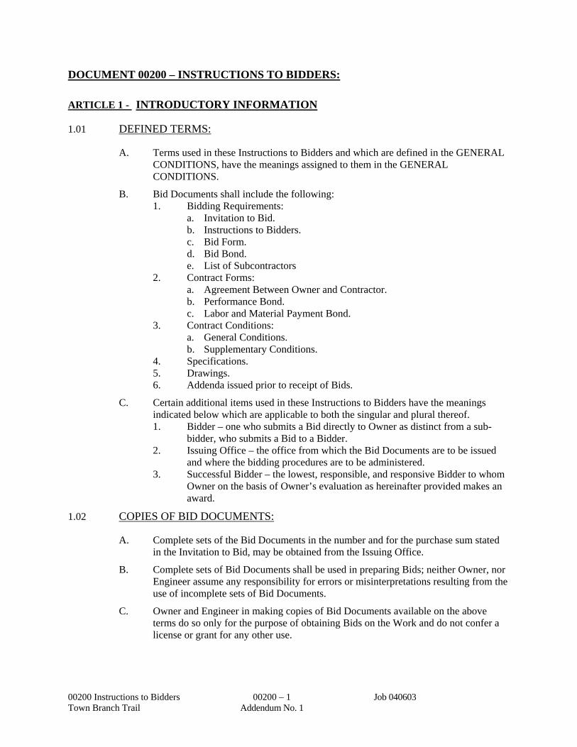
DOCUMENT 00200 – INSTRUCTIONS TO BIDDERS:
00200 Instructions to Bidders 00200 – 1 Job 040603 Town Branch Trail Addendum No. 1
ARTICLE 1 - INTRODUCTORY INFORMATION
1.01 DEFINED TERMS:
A. Terms used in these Instructions to Bidders and which are defined in the GENERAL CONDITIONS, have the meanings assigned to them in the GENERAL CONDITIONS.
B. Bid Documents shall include the following: 1. Bidding Requirements:
a. Invitation to Bid. b. Instructions to Bidders. c. Bid Form. d. Bid Bond. e. List of Subcontractors
2. Contract Forms: a. Agreement Between Owner and Contractor. b. Performance Bond. c. Labor and Material Payment Bond.
3. Contract Conditions: a. General Conditions. b. Supplementary Conditions.
4. Specifications. 5. Drawings. 6. Addenda issued prior to receipt of Bids.
C. Certain additional items used in these Instructions to Bidders have the meanings indicated below which are applicable to both the singular and plural thereof. 1. Bidder – one who submits a Bid directly to Owner as distinct from a sub-
bidder, who submits a Bid to a Bidder. 2. Issuing Office – the office from which the Bid Documents are to be issued
and where the bidding procedures are to be administered. 3. Successful Bidder – the lowest, responsible, and responsive Bidder to whom
Owner on the basis of Owner’s evaluation as hereinafter provided makes an award.
1.02 COPIES OF BID DOCUMENTS:
A. Complete sets of the Bid Documents in the number and for the purchase sum stated in the Invitation to Bid, may be obtained from the Issuing Office.
B. Complete sets of Bid Documents shall be used in preparing Bids; neither Owner, nor Engineer assume any responsibility for errors or misinterpretations resulting from the use of incomplete sets of Bid Documents.
C. Owner and Engineer in making copies of Bid Documents available on the above terms do so only for the purpose of obtaining Bids on the Work and do not confer a license or grant for any other use.
DOCUMENT 00200 – INSTRUCTIONS TO BIDDERS: (continued)
00200 Instructions to Bidders 00200 – 2 Job 040603 Town Branch Trail Addendum No. 1
1.03 QUALIFICATION OF BIDDERS:
A. Prequalification statements are not required. Owner will, however, evaluate the Bidder’s qualifications following the opening of Bids. Evaluation criteria considered will include, but not be limited to: 1. Experience and performance records on similar work. 2. Financial responsibility. 3. Ability to supply construction equipment and personnel to complete the
Work within the Contract Time. 4. Evidence of Bidder to do business in the state where the Project is located, or
covenant to obtain such qualifications prior to award of the Contract.
B. Bidders may be requested to submit financial statement and other information relating to experience and financial responsibility after bids are received and before awarding a contract.
C. Only those Bids will be considered which are submitted by Bidders who show satisfactory completion of work of type and size comparable to the Work required by these Bid Documents. 1. A list of comparable projects, including pertinent information and
identification of the owners, shall be submitted if requested. 2. See ARTICLE 5 – AWARD OF CONTRACT herein for additional
requirements after opening of Bids.
D. For Federal-Aid Projects, Bidders are not required to be licensed in the State of Arkansas at the time of bid. Bids will not be rejected if the license number is left blank at time of bidding. A Contractor’s license must be secured by the successful bidder before contracts are executed.
1.04 EXAMINATION OF CONTRACT DOCUMENTS AND SITE:
A. Before submitting a Bid, it is the responsibility of each Bidder: 1. To thoroughly examine the Contract Documents and other related data
identified in the Bid Documents (including “technical data” referred to below).
2. To visit the Site to become familiar with and satisfy Bidder as to the general, local, and Site conditions that may in any manner affect cost, progress, and performance of the Work.
3. To consider federal, state, and local laws, ordinances, rules, and regulations that may in any manner affect cost, progress, performance, and furnishing of the Work.
4. To study and carefully correlate Bidder’s knowledge and observations with the Contract Documents and such other related data.
5. To promptly notify Engineer of all conflicts, errors, ambiguities, or discrepancies which Bidder has discovered in or between the Contract Documents and such other related documents.
B. Before submitting a Bid, each Bidder shall be responsible to obtain such additional or supplementary examinations, investigations, explorations, tests, studies, and data concerning conditions (surface, subsurface, and Underground Facilities) at or contiguous to the Site or otherwise, which may affect cost, progress, performance,

DOCUMENT 00200 – INSTRUCTIONS TO BIDDERS: (continued)
00200 Instructions to Bidders 00200 – 3 Job 040603 Town Branch Trail Addendum No. 1
and furnishing of the Work or which relate to any aspect of the means, methods, techniques, sequences, or procedures of construction to be employed by Bidder, including safety precautions and programs incident thereto or which Bidder deems necessary to determine its Bid for performing and furnishing the Work in accordance with the time, price, and other terms and conditions of the Contract Documents. This shall include local shipping facilities and availability of lands if applicable.
C. In the preparation of the Contract Documents, neither reports of explorations nor tests of any Hazardous Environmental Condition at the Site of the Work have been prepared.
D. Access to the Site: 1. On request, Owner will provide each Bidder access to the Site to conduct
such examinations, investigations, explorations, tests, and studies as each Bidder deems necessary for submission of his Bid. Bidder shall fill all holes, clean up, and restore the Site to its former conditions upon completion of such explorations, investigations, tests, and studies.
2. The lands upon which the Work is to be performed, rights-of-way, and easements for access thereto and other lands designated for use by Contractor in performing the Work are identified in the Contract Documents. All additional lands and access thereto required for temporary construction facilities, construction equipment, or storage of Materials and Equipment to be incorporated in the Work are to be obtained and paid for by Contractor. Easements for permanent structures or permanent changes in existing facilities are to be obtained and paid for by Owner unless otherwise provided in the Contract Documents.
3. Property owners affected by the Work are named on the Drawings where known, but the accuracy of such ownership is not guaranteed. Bidders shall verify and make their own arrangements with such property owners for any access needed in connection with the preparation of Bids.
E. Subsurface Information: 1. Certain subsurface information has been obtained at, or in the vicinity of, the
Site of the Work. 2. Reports used in preparation of Contract Documents:
a. In the preparation of the Contract Documents, the following reports of explorations and tests of subsurface conditions at or contiguous to the Site of the Work were used: (1) Report dated March, 2012, prepared by Grubbs, Hoskyn, Barton
& Wyatt, Inc.; entitled Geotechnical Geotechnical Investigation Town Branch Trail Fayetteville, Arkansas, which may be reviewed at the City Development Services Office at 125 W. Mountain Fayetteville, Arkansas
3. Copies of the Log(s) of Boring(s) from the above referenced Report (E.2.a(1)) are included within the Specifications.
a. Soil characteristics provided in any soil reports, or as shown on boring logs within the plans or specifications, are representative only at the location of the sample taken, and neither the Owner, Engineer nor Engineer’s consultants will be responsible for variations in the
DOCUMENT 00200 – INSTRUCTIONS TO BIDDERS: (continued)
00200 Instructions to Bidders 00200 – 4 Job 040603 Town Branch Trail Addendum No. 1
soil characteristics at other locations. Such reports and drawings are not Contract Documents.
b. Any subsurface information, whether included in the plans, specifications, or otherwise made available to Contractor, was obtained and intended for the Owner’s design and estimating purposes only.
c. The Contractor may not rely upon or make any claim against Owner, Engineer, or Engineer’s Consultants with respect to (1) the completeness of such reports and drawings for Contractor’s purposes, including, but not limited to, any aspects of the means, methods, techniques, sequences, and procedures of construction to be employed by the Contractor and safety precautions and programs incident thereto, (2) other data, interpretations, opinions, and information contained in such reports or shown or indicated in such drawings, (3) any Contractor interpretation or other conclusion drawn from any data, interpretations, opinions, or information.
4. Copies of the above referenced Report (E.2.a(1)) may be purchased only by prospective Bidders who request such subsurface information. Copies may be purchased from the ENGINEER at the cost of reproduction. Purchased copies are not returnable and no refund or reimbursement will be made.
5. There is no express or implied guarantee as to the accuracy or completeness of the subsurface information, nor of the interpretation thereof by the Owner, the Engineer, or any of their representatives.
6. The subsurface information or copies thereof do not form a part of this or any contract document issued by the Owner or Engineer.
7. Each prospective Bidder shall make its own interpretation of subsurface information issued to it and shall, at its own expense, make surveys and investigations as it may deem necessary to evaluate conditions which will affect performance of the work.
8. In the preparation of the Contract Documents, no drawings of physical conditions in or relating to existing surface or subsurface structures which are at or contiguous to the Site of the Work were used.
F. The submission of a Bid will constitute an incontrovertible representation by the Bidder that he has complied with every requirement of this paragraph “Examination of Contract Documents and Site,” and that the Bid Documents are sufficient in scope and detail to indicate and convey understanding of all terms and conditions for performance and furnishing of the Work.
1.05 INTERPRETATIONS, MODIFICATIONS, AND ADDENDA:
A. Any Bidder who discovers ambiguities, inconsistencies, or errors or is in doubt as to the meaning or intent of any part of the Bid Documents shall promptly request an interpretation from Engineer. Interpretations or clarifications considered necessary by Engineer in response to such requests will be issued by Addenda mailed or delivered to all parties recorded by Engineer as having received the Bid Documents.
DOCUMENT 00200 – INSTRUCTIONS TO BIDDERS: (continued)
00200 Instructions to Bidders 00200 – 5 Job 040603 Town Branch Trail Addendum No. 1
B. Addenda may also be issued to modify the Bid Documents as deemed advisable by Owner or Engineer.
C. Because of the time required to publish and deliver, no Addenda will be issued within the last 7 days before the date of opening Bids. However, an addendum that affects the time, date or location of the bid opening may be issued as little as two (2) days before the date of opening bids.
D. Only questions answered by formal written Addenda will be binding. Oral and other interpretations or clarifications will be without legal effect.
1.06 PREBID CONFERENCE:
A non-mandatory pre-bid conference will held at the City of Fayetteville, Purchasing Division, Room 326 – City Hall, at 10:00 AM Friday, January 3, 2013, located at 113 West Mountain Street. All interested parties are strongly encouraged to attend the meeting.
1.07 LABOR-RELATED REGULATIONS:
A. Pursuant to Arkansas Code Annotated 22-9-203, the City of Fayetteville encourages all qualified minority and women business enterprises to bid on and receive contracts for goods, services, and construction. Also, City of Fayetteville encourages all general contractors to subcontract portions of their contract to qualified, small, minority, and women business enterprises.
B. This contract is subject to applicable labor laws, non-discrimination provisions, wage rate laws and other federal laws including the Fair Labor Standards Acts of 1938. The Works Hours Act of 1962 and Title VI of the Civil rights Act of 1964 also apply.
ARTICLE 2 - BASIS OF BIDDING
2.01 SPECIFIED EQUIPMENT AND MATERIALS:
A. Substitutions will be considered only after the Effective Date of the Agreement and as set forth in the GENERAL CONDITIONS.
2.02 INDIRECT COSTS:
A. Taxes: 1. All applicable sales, use, compensating, or other taxes to be paid or withheld
by Bidder, now imposed by any taxing authority, on Equipment and Materials to be incorporated in the Work, and on any or all other cost items entering into the Contract Price, shall be included in the Bid price.
2. The Bidder shall include all such taxes except those on Equipment and Materials, if any, furnished by Owner or others, or exempted by the state, and Bidder shall furnish taxing authorities any information or reports pertaining thereto as required.
B. The cost of all construction licenses, building and other permits, and governmental inspections required by public authorities for performing the Work, which are

DOCUMENT 00200 – INSTRUCTIONS TO BIDDERS: (continued)
00200 Instructions to Bidders 00200 – 6 Job 040603 Town Branch Trail Addendum No. 1
applicable at the time Bids are opened and which are not specified to be obtained by Owner, shall be included in the Bid price.
C. The cost of all royalties and license fees on Equipment and Materials to be furnished and incorporated in the Work shall be included in the Bid price.
D. Tests, inspections, and related activities called for throughout the Bid Documents are a responsibility of Contractor unless specified otherwise. The Bid shall include all costs arising from such responsibility.
E. The cost of all electrical, water, gas, telephone, sanitary, and similar facilities and services required by Contractor in performing the Work shall be included in the Bid price unless specified otherwise.
2.03 SUBCONTRACTORS:
A. No Bid shall be based upon aggregate of Subcontractors performing more than 60 percent of the total Work.
B. The experience, past performance, and ability of each proposed Subcontractor will be considered in the evaluation of Bids. Any Subcontractor so requested shall be required to furnish experience statements prior to the Notice of Awards.
C. No Contractor shall be required to employ any Subcontractor, other person, or organization against whom Contractor has reasonable objection. Owner or Engineer may accept or reject Subcontractors in accordance with Paragraph 6.05 of the GENERAL CONDITIONS.
2.04 CONTRACT TIMES:
A. The number of days within which, or the dates by which, the Work is to achieve Substantial Completion and also final completion and be ready for final payment shall be as stated in the Agreement.
B. Provisions for liquidated damages, if any, are as set forth in the Agreement.
ARTICLE 3 - BIDDING PROCEDURE
3.01 PREPARATION OF BID:
A. One set of bound documents included with the purchased set of drawings and specifications shall be used for the Bid.
B. The Bid Forms shall be filled out in detail in black ink and signed by the Bidder. Forms shall not be removed from the bound document.
C. Bids by partnerships shall be executed in the partnership name and signed by a partner whose title shall appear under his signature, and the official address of the partnership shall be shown below the signature.
D. Bids by corporations shall be executed in the corporate name by the president or a vice president (or other corporate officer accompanied by evidence of authority to sign), and the corporate seal shall be affixed and attested by the secretary or an

DOCUMENT 00200 – INSTRUCTIONS TO BIDDERS: (continued)
00200 Instructions to Bidders 00200 – 7 Job 040603 Town Branch Trail Addendum No. 1
assistant secretary. The corporate address and state of incorporation shall be shown below the signature.
E. Names of all persons signing shall be printed below their signatures.
F. A power of attorney shall accompany the signature of anyone not otherwise authorized to bind the Bidder.
G. The Bid shall contain an acknowledgement of receipt of all Addenda, the numbers of which shall be filled in on the Bid Form.
H. The address to which communications regarding the Bids are to be directed shall be shown.
3.02 METHOD OF BIDDING:
A. Bids will be received on a Unit Prices basis as set forth in the Bid Form.
B. Firm Bids are required.
C. Schedule of Unit Prices: 1. The Bidder shall complete the “Schedule of Unit Prices” included in the Bid
(and shall accept all fixed Unit Prices listed therein.) 2. The total Bid price will be determined as the sum of the products of the
estimated quantity of each item and the Unit Price set forth in the “Schedule of Unit Prices.” The final Contract Price shall be subject to adjustment according to final measured, used, or delivered quantities, and the Unit Prices set forth in the “Schedule of Unit Prices” will apply to such final quantities except that if quantities vary more than 25 percent above or below estimated quantities, Unit Prices will be subject to change by Change Order.
3.03 SUBCONTRACTORS INFORMATION SUBMITTED WITH BID:
A. Bidders shall submit to Owner with the Bid, the List of Subcontractors contained in the Project Manual as Document 00430, completed with names of all such Subcontractors, Suppliers, and other persons and organizations proposed for those portions of the Work for which such identification is required. The list shall be supplemented by an experience statement with pertinent information regarding similar projects and other evidence of qualification for each such Subcontractor, Supplier, person, or organization, if requested by Engineer. If, after due investigation, Owner or Engineer has reasonable objection to any proposed Subcontractor, Supplier, or other person or organization, Owner may, before the Notice of Award is given, request the apparent Successful Bidder to submit an acceptable substitute without an increase in the Bid. If the apparent Successful Bidder declines to make any such substitution, Owner may award the Contract to the next lowest Bidder that proposes to use acceptable Subcontractors, Suppliers, and other persons and organizations. The declining to make requested substitutions will not constitute grounds for sacrificing the bid security of any Bidder. Any Subcontractor, Supplier, or other person or organization listed and to whom Owner or Engineer does not make written objection prior to the giving of the Notice of Award will be deemed acceptable to Owner and Engineer subject to revocation as provided in Paragraph 6.05 of the General Conditions.

DOCUMENT 00200 – INSTRUCTIONS TO BIDDERS: (continued)
00200 Instructions to Bidders 00200 – 8 Job 040603 Town Branch Trail Addendum No. 1
3.04 MANUFACTURERS SUBMITTED WITH BID:
Not applicable.
3.05 FORMS TO BE SUBMITTED:
A. The following forms shall be completed and submitted with the Bid:. 1. DOCUMENT 00400 BID FORM 2. Bid Security as cashier’s check from a bank in the State of Arkansas, or Bid
Bond (DOCUMENT 00410)
3.06 BID SECURITY:
A. Each Bid shall be accompanied by Bid security, payable to Owner, of the amount stipulated in the Invitation to Bid.
B. The required security shall be in the form of a cashier’s check from a bank in the State of Arkansas or a Bid Bond on the form prescribed by the AIA, Document A310, or on similar form attached.
C. Bid Bond shall be executed by a surety meeting the requirements set forth for “Surety Bonds” in the GENERAL CONDITIONS.
D. Bid security of the Successful Bidder will be retained until Bidder has executed the Agreement and furnished the required surety Bonds as set forth in the GENERAL CONDITIONS, whereupon Bid security will be returned. If the Successful Bidder fails to execute the Agreement and furnish the surety Bonds within 15 days after the date of Notice of Award, Owner may annul the Notice of Award, and Bid security of that Bidder will be forfeited to Owner.
E. The Bid security of any Bidder whom Owner believes to have a reasonable chance of receiving the award may be retained by Owner until the earlier of 10 days after the Effective Date of the Agreement and the required surety Bonds furnished, or the 91st day after the Bid opening. Bid security of other Bidders will be returned within 10 days of the bid opening.
3.07 SUBMISSION OF BID:
A. Bids shall be submitted at the time and place designated in the Invitation to Bid.
B. Bid Documents with accompanying Bid security and other required information shall be enclosed in an opaque sealed envelope marked with the following: 1. Project name. 2. Bid number. 3. Name and address of Bidder. 4. Contractor’s license number (Not required for Federal Aid Projects).
C. If the Bid is sent by mail or other delivery system, the sealed envelope shall be enclosed in a separate envelope with the notation “Sealed Bid Enclosed” on the face thereof.

DOCUMENT 00200 – INSTRUCTIONS TO BIDDERS: (continued)
00200 Instructions to Bidders 00200 – 9 Job 040603 Town Branch Trail Addendum No. 1
3.08 MODIFICATION OR WITHDRAWAL OF BIDS:
A. Bids may be modified or withdrawn by an appropriate document duly executed (in the manner that Bid must be executed) and delivered to the place where Bids are to be submitted at any time prior to the opening of Bids.
B. If, within 24 hours after Bids are opened, any Bidder files a duly signed written notice with Owner and promptly thereafter demonstrates to the reasonable satisfaction of Owner that there was a material and substantial mistake in the preparation of his Bid, that Bidder may withdraw its Bid, and the Bid security will be returned. Thereafter, that Bidder will be disqualified from further bidding on the Work to be provided under the Contract Documents.
ARTICLE 4 - OPENING OF BIDS
4.01 OPENING OF BIDS:
A. Bids will be opened and (unless obviously non-responsive) read aloud publicly at the place where Bids are to be submitted. An abstract of the amounts of the base Bids will be made available to Bidders after the opening of Bids.
B. All Bids shall remain open for a period of 90 days after Bids are opened, but Owner may, at his sole discretion, release any Bid and return the Bid security at any time prior to that date.
ARTICLE 5 - AWARD OF CONTRACT
5.01 OWNER’s RIGHT TO REJECT BIDS:
A. Owner reserves the right to reject any or all Bids, including without limitation the rights to reject any or all nonconforming, non-responsive, unbalanced, or conditional Bids and to reject the Bid of any Bidder if Owner believes that it would not be in the best interest of the Project to make an award to that Bidder, whether because the Bid is not responsive or the Bidder is unqualified or of doubtful financial ability or fails to meet any other pertinent standard or criteria established by Owner. Owner also reserves the right to waive all informalities not involving price, times, or changes in the Work and to negotiate Contract terms with the Successful Bidder. (Discrepancies between the multiplication of units of Work and Unit Prices will be resolved in favor of the Unit Prices.) Discrepancies between the indicated sum of any column of figures and the correct sum thereof will be resolved in favor of the correct sum. Discrepancies between words and figures will be resolved in favor of the words.
B. All Bidders must agree that such rejection shall be without liability on the part of the Owner nor shall the Bidders seek recourse of any kind against the Owner because of such rejections. The filing of any Bid shall constitute an agreement of the Bidder to these conditions.
5.02 EVALUATION OF BIDS:
A. In evaluating Bids, Owner will consider the qualifications of the Bidders, whether or not the Bids comply with the prescribed requirements (and such Alternates, Unit

DOCUMENT 00200 – INSTRUCTIONS TO BIDDERS: (continued)
00200 Instructions to Bidders 00200 – 10 Job 040603 Town Branch Trail Addendum No. 1
Prices) and other data, as may be requested in the Bid Form or prior to the Notice of Award. Owner must accept Alternates in numerical order.
B. Owner may consider the qualifications and experience of Subcontractors, Suppliers, and other persons and organizations proposed for those portions of the Work as to which the identity of Subcontractors, Suppliers, and other persons and organizations is requested per Paragraph 5.02E of this document.
C. Owner may conduct such investigations as he deems necessary to assist in the evaluation of any Bid and to establish the responsibility, qualifications, and financial ability of the Bidders, proposed Subcontractors, and other persons and organizations to perform and furnish the Work in accordance with the Contract Documents to Owner’s satisfaction within the prescribed time.
D. Owner reserves the right to reject the Bid of any Bidder who does not pass any such evaluation to Owner’s satisfaction.
E. Within 10 days after Bids are opened, and if requested by the Owner or the Engineer, the apparent Successful Bidder, and any other Bidder so requested, shall submit supplemental information including an experience statement with pertinent information regarding similar projects and other evidence of qualification for each such Subcontractor, Supplier, person, or organization, proposed by the Bidder for consideration as specified in ARTICLE 3 paragraph 3.03 above. The use of Subcontractors listed by Bidder (Document 00430) and accepted by Owner prior to the Notice of Award will be required in the performance of the Work.
F. Within 10 days after the Bids are opened, the apparent Successful Bidder, and any other Bidder so requested, shall submit an itemized breakdown of any lump sum portion of its Bid. This breakdown must include a separate item for each major category of work and each major piece of equipment. This breakdown may or may not be reflected in subsequent time schedule submittals.
G. The award of the Contract, if it is awarded, will be to the lowest, responsive, responsible Bidder whose evaluation by Owner indicates to Owner that the award will be in the best interest of Project and Owner.
5.03 NOTICE OF AWARD:
A. After considering the basis of award and evaluation of Bids, if the Contract is to be awarded, Owner shall within 90 days after the date of opening Bids notify the Successful Bidder of acceptance of his Bid (indicating which, if any, Alternate Bids have been accepted).
ARTICLE 6 - SIGNING OF AGREEMENT
6.01 When Owner gives Notice of Award to Successful Bidder, Engineer will issue the required number of unbound, unsigned counterparts of the Agreement and other Contract Documents to Successful Bidder.
6.02 Within 15 days thereafter, Contractor (Successful Bidder) shall sign all copies of the Agreement leaving the dates blank, insert the properly executed Bonds, power of attorney documents, and other required documents in the appropriate places, and deliver all copies to Owner.

DOCUMENT 00200 – INSTRUCTIONS TO BIDDERS: (continued)
00200 Instructions to Bidders 00200 – 11 Job 040603 Town Branch Trail Addendum No. 1
6.03 Within 10 days thereafter, Owner will execute all copies of the Agreement and insert the Date of Contract in the Agreement, Bonds, and power of attorney documents. Owner will provide the executed Contract Documents to Engineer for binding and distribution as required. Each duly executed counterpart will be accompanied by a complete set of Drawings with appropriate identification.
END OF DOCUMENT 00200
DOCUMENT 00400 –BID FORM
City of Fayetteville 00400 – 1
Town Branch Trail Addendum No. 1
Contract Name: Town Branch Trail
Bid Number 13-58
BID TO:
Owner: The City of Fayetteville, Arkansas
113 West Mountain Street
Fayetteville, Arkansas 72701
BID FROM:
Bidder:
ARTICLE 1 - INTENT
1.01 The undersigned Bidder proposes and agrees, if this Bid is accepted, to enter into an
agreement with Owner in the form included in the Contract Documents to perform
and furnish all Work as specified or indicated in the Contract Documents for the Bid
price and within the Bid time indicated in this Bid and in accordance with the other
terms and conditions of the Contract Documents.
ARTICLE 2 - TERMS AND CONDITIONS
2.01 Bidder accepts all of the terms and conditions of the Invitation to Bid and
Instructions to Bidders, including without limitation those dealing with the
disposition of Bid security. This Bid will remain subject to acceptance for 180 days
after the day of Bid opening. Bidder will sign and deliver the required number of
counterparts of the Agreement with the Bonds and other documents required by the
Bidding Requirements within 15 days after the date of Owner’s Notice of Award.
DOCUMENT 00400 –BID FORM (continued)
City of Fayetteville 00400 – 2
Town Branch Trail Addendum No. 1
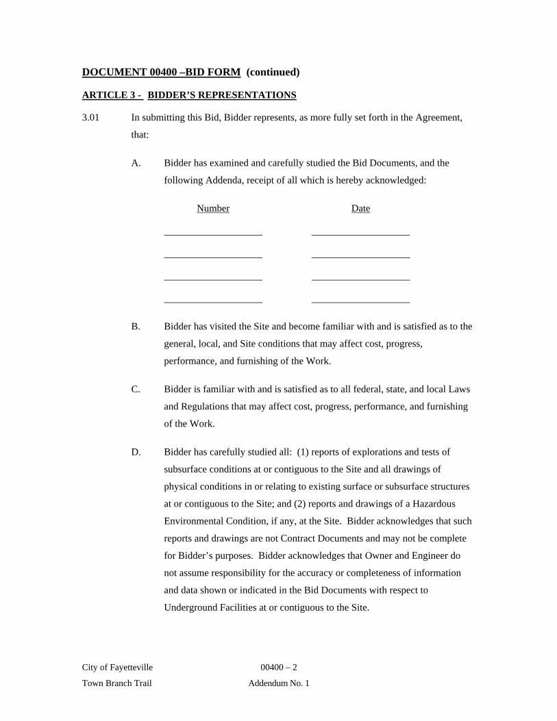
ARTICLE 3 - BIDDER’S REPRESENTATIONS
3.01 In submitting this Bid, Bidder represents, as more fully set forth in the Agreement,
that:
A. Bidder has examined and carefully studied the Bid Documents, and the
following Addenda, receipt of all which is hereby acknowledged:
Number Date
B. Bidder has visited the Site and become familiar with and is satisfied as to the
general, local, and Site conditions that may affect cost, progress,
performance, and furnishing of the Work.
C. Bidder is familiar with and is satisfied as to all federal, state, and local Laws
and Regulations that may affect cost, progress, performance, and furnishing
of the Work.
D. Bidder has carefully studied all: (1) reports of explorations and tests of
subsurface conditions at or contiguous to the Site and all drawings of
physical conditions in or relating to existing surface or subsurface structures
at or contiguous to the Site; and (2) reports and drawings of a Hazardous
Environmental Condition, if any, at the Site. Bidder acknowledges that such
reports and drawings are not Contract Documents and may not be complete
for Bidder’s purposes. Bidder acknowledges that Owner and Engineer do
not assume responsibility for the accuracy or completeness of information
and data shown or indicated in the Bid Documents with respect to
Underground Facilities at or contiguous to the Site.

DOCUMENT 00400 –BID FORM (continued)
City of Fayetteville 00400 – 3
Town Branch Trail Addendum No. 1
E. Bidder has obtained and carefully studied (or assumes responsibility for
having done so) all such additional or supplementary examinations,
investigations, explorations, tests, studies, and data concerning conditions
(surface, subsurface, and Underground Facilities) at or contiguous to the Site
or otherwise which may affect cost, progress, performance, or furnishing of
the Work or which relate to any aspect of the means, methods, techniques,
sequences, and procedures of construction to be employed by Bidder and
safety precautions and programs incident thereto.
F. Bidder does not consider that any additional examinations, investigations,
explorations, tests, studies, or data are necessary for the determination of this
Bid for performing and furnishing of the Work in accordance with the times,
price, and other terms and conditions of the Contract Documents.
G. Bidder is aware of the general nature of work to be performed by Owner and
others at the Site that relates to Work for which this Bid is submitted as
indicated in the Contract Documents.
H. Bidder has correlated the information known to Bidder, information and
observations obtained from visits to the Site, reports, and drawings identified
in the Contract Documents, and all additional examinations, investigations,
explorations, tests, studies, and data with the Contract Documents.
I. Bidder has given Engineer written notice of all conflicts, errors, ambiguities,
or discrepancies that Bidder has discovered in the Contract Documents, and
the written resolution thereof by Engineer is acceptable to Bidder.
J. The Contract Documents are generally sufficient to indicate and convey
understanding of all terms and conditions for performing and furnishing the
Work for which this Bid is submitted.
K. This Bid is genuine and not made in the interest of or on behalf of any
undisclosed person, firm, or corporation and is not submitted in conformity
with any agreement or rules of any group, association, organization, or
corporation; Bidder has not directly or indirectly induced or solicited any
DOCUMENT 00400 –BID FORM (continued)
City of Fayetteville 00400 – 4
Town Branch Trail Addendum No. 1
other Bidder to submit a false or sham bid; Bidder has not solicited or
induced any person, firm, or a corporation to refrain from bidding; and
Bidder has not sought by collusion to obtain for himself any advantage over
any other Bidder or over Owner.
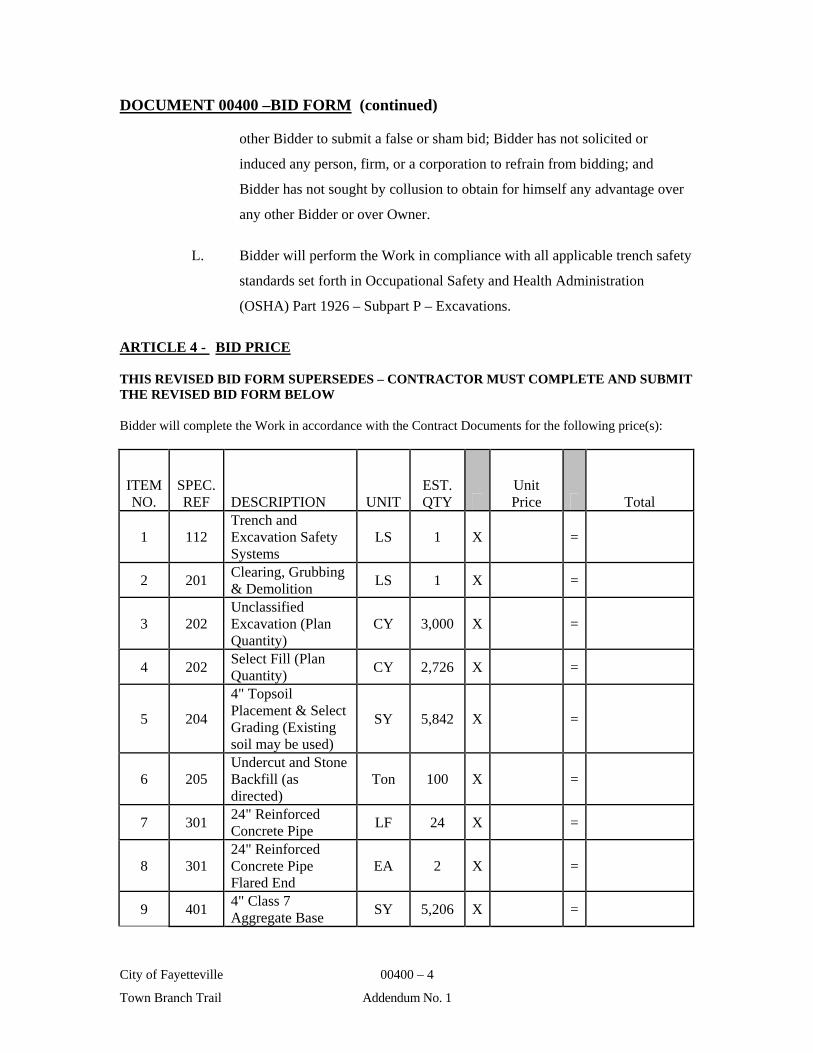
L. Bidder will perform the Work in compliance with all applicable trench safety
standards set forth in Occupational Safety and Health Administration
(OSHA) Part 1926 – Subpart P – Excavations.
ARTICLE 4 - BID PRICE
THIS REVISED BID FORM SUPERSEDES – CONTRACTOR MUST COMPLETE AND SUBMIT THE REVISED BID FORM BELOW
Bidder will complete the Work in accordance with the Contract Documents for the following price(s):
ITEM NO.
SPEC. REF DESCRIPTION UNIT
EST. QTY
Unit Price Total
1 112 Trench and Excavation Safety Systems
LS 1 X =
2 201 Clearing, Grubbing & Demolition
LS 1 X =
3 202 Unclassified Excavation (Plan Quantity)
CY 3,000 X =
4 202 Select Fill (Plan Quantity)
CY 2,726 X =
5 204
4" Topsoil Placement & Select Grading (Existing soil may be used)
SY 5,842 X =
6 205 Undercut and Stone Backfill (as directed)
Ton 100 X =
7 301 24" Reinforced Concrete Pipe
LF 24 X =
8 301 24" Reinforced Concrete Pipe Flared End
EA 2 X =
9 401 4" Class 7 Aggregate Base
SY 5,206 X =
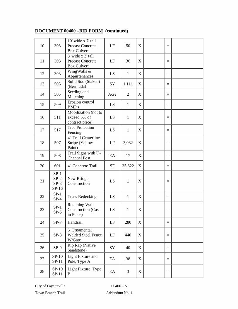
DOCUMENT 00400 –BID FORM (continued)
City of Fayetteville 00400 – 5
Town Branch Trail Addendum No. 1
10 303 10' wide x 7' tall Precast Concrete Box Culvert
LF 50 X =
11 303 8' wide x 3' tall Precast Concrete Box Culvert
LF 36 X =
12 303 WingWalls & Appurtenances
LS 1 X =
13 505 Solid Sod (Staked) (Bermuda)
SY 1,111 X =
14 505 Seeding and Mulching
Acre 2 X =
15 509 Erosion control BMP's
LS 1 X =
16 511 Mobilization (not to exceed 5% of contract price)
LS 1 X =
17 517 Tree Protection Fencing
LS 1 X =
18 507 4" Trail Centerline Stripe (Yellow Paint)
LF 3,082 X =
19 508 Trail Signs with U-Channel Post
EA 17 X =
20 601 4" Concrete Trail SF 35,622 X =
21
SP-1 SP-2 SP-3
SP-16
New Bridge Construction
LS 1 X =
22 SP-1 SP-4
Truss Redecking LS 1 X =
23 SP-1 SP-5
Retaining Wall Construction (Cast in Place)
LS 1 X =
24 SP-7 Handrail LF 280 X =
25 SP-8 6' Ornamental Welded Steel Fence W/Gate
LF 440 X =
26 SP-9 Rip Rap (Native Sandstone)
SY 40 X =
27 SP-10 SP-11
Light Fixture and Pole, Type A
EA 38 X =
28 SP-10 SP-11
Light Fixture, Type B
EA 3 X =

DOCUMENT 00400 –BID FORM (continued)
City of Fayetteville 00400 – 6
Town Branch Trail Addendum No. 1
29 SP-12 1 1/2" Electrical Conduit (Schedule 40 PVC)
LF 3,082 X =
30 SP-12 9" x 11" Fiberglass/Polymer Concrete Pull Box
EA 38 X =
31 SP-13 3/4" Galvanized Rigid Steel Conduit
LF 208 X =
32 SP-14 No. 8 AWG Copper Conductor
LF 8,721 X =
33 SP-10 SP-12 SP-15
Electrical Service Equipment Pedestals
EA 2 X =
34 See
Terms Insurance & Bonding
LS 1 X =
TOTAL AMOUNT BID $_____________________________
ARTICLE 5 - CONTRACT TIMES
5.01 Bidder agrees that the Work will be substantially completed and completed and ready
for final payment within the number of calendar days indicated in the Agreement.
5.02 Bidder accepts the provisions of the Agreement as to liquidated damages in the event
of failure to complete the Work within the times specified in the Agreement.
ARTICLE 6 - BID CONTENT
6.01 The following documents are attached to and made a condition of this Bid:
A. Required Bid security in the form of a certified or bank cashier’s check or a
Bid Bond and in the amount of
____________________________ Dollars ($ ).
B. A tabulation of Subcontractors and other persons and organizations required
to be identified in this Bid.

DOCUMENT 00400 –BID FORM (continued)
City of Fayetteville 00400 – 7
Town Branch Trail Addendum No. 1
ARTICLE 7 - COMMUNICATIONS
7.01 Communications concerning this Bid shall be addressed to the Bidder as follows:
Phone No.
FAX No.
ARTICLE 8 - TERMINOLOGY
8.01 The terms used in this Bid which are defined in the GENERAL CONDITIONS or
Instructions to Bidders will have the meanings assigned to them.
SUBMITTED on , 20___.
If Bidder is:
An Individual
Name (type or printed):
By: (SEAL)
(Individual’s Signature)
Doing business as:
Business address:
Phone No.: FAX No.:

DOCUMENT 00400 –BID FORM (continued)
City of Fayetteville 00400 – 8
Town Branch Trail Addendum No. 1
A Partnership
Partnership Name: (SEAL)
By:
(Signature of general partner – attach evidence of authority to sign)
Name (type or printed):
Business address:
Phone No.: FAX No.:
A Corporation
Corporation Name: (SEAL)
State of Incorporation:
Type (General Business, Professional, Service, Limited Liability):
By:
(Signature – attach evidence of authority to sign)
Name (type or printed):
Title:
(CORPORATE SEAL)
Attest:
(Signature of Corporate Secretary)
Business address:
Phone No.: FAX No.:
END OF DOCUMENT 00400
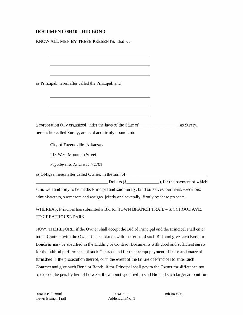
DOCUMENT 00410 – BID BOND
00410 Bid Bond 00410 – 1 Job 040603 Town Branch Trail Addendum No. 1
KNOW ALL MEN BY THESE PRESENTS: that we
as Principal, hereinafter called the Principal, and
a corporation duly organized under the laws of the State of __________________ as Surety,
hereinafter called Surety, are held and firmly bound unto
City of Fayetteville, Arkansas
113 West Mountain Street
Fayetteville, Arkansas 72701
as Obligee, hereinafter called Owner, in the sum of _____________________________________
_________________________________ Dollars ($_______________), for the payment of which
sum, well and truly to be made, Principal and said Surety, bind ourselves, our heirs, executors,
administrators, successors and assigns, jointly and severally, firmly by these presents.
WHEREAS, Principal has submitted a Bid for TOWN BRANCH TRAIL – S. SCHOOL AVE.
TO GREATHOUSE PARK
NOW, THEREFORE, if the Owner shall accept the Bid of Principal and the Principal shall enter
into a Contract with the Owner in accordance with the terms of such Bid, and give such Bond or
Bonds as may be specified in the Bidding or Contract Documents with good and sufficient surety
for the faithful performance of such Contract and for the prompt payment of labor and material
furnished in the prosecution thereof, or in the event of the failure of Principal to enter such
Contract and give such Bond or Bonds, if the Principal shall pay to the Owner the difference not
to exceed the penalty hereof between the amount specified in said Bid and such larger amount for
DOCUMENT 00410 – BID BOND (continued)
00410 Bid Bond 00410 – 2 Job 040603 Town Branch Trail Addendum No. 1
which the Owner may in good faith contract with another party to perform the Work covered by
said Bid, then this obligation shall be null and void, otherwise to remain in full force and effect.
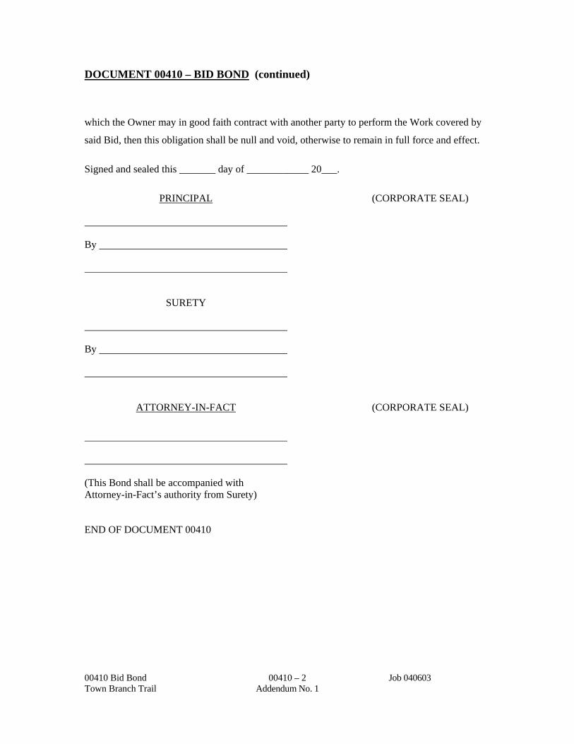
Signed and sealed this _______ day of ____________ 20___.
PRINCIPAL (CORPORATE SEAL)
By
SURETY
By
ATTORNEY-IN-FACT (CORPORATE SEAL)
(This Bond shall be accompanied with Attorney-in-Fact’s authority from Surety)
END OF DOCUMENT 00410

DOCUMENT 00430 – LIST OF SUBCONTRACTORS
00430 List of Subcontractors 00430 – 1 Job 040603 Town Branch Trail Addendum No. 1
In compliance with the Instructions to Bidders and other Contract Documents, the undersigned submits the following names of Subcontractors to be used in performing the Work for TOWN BRANCH TRAIL – S. SCHOOL AVE TO GREATHOUSER PARK
Bidder certifies that all Subcontractors listed are eligible to perform the Work.
Subcontractor's Work Subcontractor’s Name Expected Percentage and Address or Value Excavation/Grading
Concrete
Class 7 ABC
ACHM
Pavement Markings
SWPPP/Erosion Control
Sewer Line
Water line
Other (designate)
NOTE: This form must be submitted in accordance with the Instructions to Bidders.
Bidder’s Signature
END OF DOCUMENT 00430
10/9/98 Page 1 of 2
CITY OF FAYETTEVILLE
SUPPLEMENT TO PROPOSAL
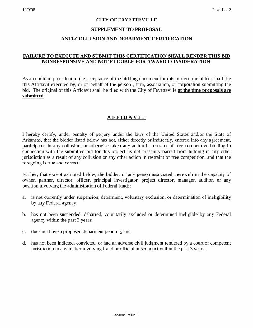
ANTI-COLLUSION AND DEBARMENT CERTIFICATION FAILURE TO EXECUTE AND SUBMIT THIS CERTIFICATION SHALL RENDER THIS BID
NONRESPONSIVE AND NOT ELIGIBLE FOR AWARD CONSIDERATION. As a condition precedent to the acceptance of the bidding document for this project, the bidder shall file this Affidavit executed by, or on behalf of the person , firm, association, or corporation submitting the bid. The original of this Affidavit shall be filed with the City of Fayetteville at the time proposals are submitted.
A F F I D A V I T I hereby certify, under penalty of perjury under the laws of the United States and/or the State of Arkansas, that the bidder listed below has not, either directly or indirectly, entered into any agreement, participated in any collusion, or otherwise taken any action in restraint of free competitive bidding in connection with the submitted bid for this project, is not presently barred from bidding in any other jurisdiction as a result of any collusion or any other action in restraint of free competition, and that the foregoing is true and correct. Further, that except as noted below, the bidder, or any person associated therewith in the capacity of owner, partner, director, officer, principal investigator, project director, manager, auditor, or any position involving the administration of Federal funds: a. is not currently under suspension, debarment, voluntary exclusion, or determination of ineligibility
by any Federal agency; b. has not been suspended, debarred, voluntarily excluded or determined ineligible by any Federal
agency within the past 3 years; c. does not have a proposed debarment pending; and d. has not been indicted, convicted, or had an adverse civil judgment rendered by a court of competent
jurisdiction in any matter involving fraud or official misconduct within the past 3 years.
Addendum No. 1

10/9/98 Page 2 of 2
CITY OF FAYETTEVILLE
SUPPLEMENT TO PROPOSAL
ANTI-COLLUSION AND DEBARMENT CERTIFICATION FAILURE TO EXECUTE AND SUBMIT THIS CERTIFICATION SHALL RENDER THIS BID
NONRESPONSIVE AND NOT ELIGIBLE FOR AWARD CONSIDERATION. EXCEPTIONS:
Applied To Initiating Agency Dates of Action
Exceptions will not necessarily result in denial of award, but will be considered in determining bidder responsibility. Providing false information may result in criminal prosecution or administrative sanctions. JOB NO. (Name of Bidder) F.A.P. NO. (Signature)
(Date Executed) (Title of Person Signing) The following Notary Public certification is OPTIONAL and may or may not be completed at the Contractor's discretion. State of ____________________________ ) County of ___________________________ )ss. _______________________________________, being duly sworn, deposes and says that he is _______________________________________ of __________________________________________ (Title) (Name of Bidder) and that the above statements are true and correct. Subscribed and Sworn to before me this _____ day of ____________________, 20_____. My commission expires:______________________________________ ______________________________________________ (Notary Public) (NOTARY SEAL)
Addendum No. 1

7/26/96 Page 1 of 1
CITY OF FAYETTEVILLE
SUPPLEMENT TO PROPOSAL
CERTIFICATION FOR FEDERAL-AID CONTRACTS
The prospective contractor certifies, by signing and submitting this proposal, to the best of his or her knowledge and belief, that:
1 No Federal appropriated funds have been paid or will be paid, by or on his or her behalf, to any
person for influencing or attempting to influence an officer or employee of any Federal agency, a Member of Congress, an officer or employee of Congress, or any employee of a Member of Congress in connection with the awarding of any Federal contract, the making of any Federal grant, the making of any Federal loan, the entering into of any cooperative agreement, and the extension, continuation, renewal, amendment, or modification of any Federal contract, grant, loan, or cooperative agreement.
2 If any funds other than Federal appropriated funds have been paid or will be paid to any person for
influencing or attempting to influence an officer or employee of any Federal agency, a Member of Congress, an officer or employee of Congress, or an employee of a Member of Congress in connection with this Federal-Aid contract, the prospective contractor shall complete and submit Standard Form-LLL, "Disclosure of Lobbying Activities", in accordance with its instructions. (Available from Arkansas State Highway and Transportation Department, Programs and Contracts Division).
This Certification is a material representation of fact upon which reliance was placed when this transaction was made or entered into. This Certification is a prerequisite for making or entering into this transaction imposed by Section 1352, Title 31, U. S. Code. During the period of performance of this contract, the contractor and all lower tier subcontractors must file a Form-LLL at the end of each calendar year quarter in which there occurs any event that requires disclosure or that materially affects the accuracy of the information contained in any previously filed disclosure form. Any person who fails to file the required Certification shall be subject to a civil penalty of not less than $10,000 and not more than $100,000 for each failure. The prospective contractor also agrees by submitting his or her proposal that he or she shall require that the language of this Certification be included in all lower tier subcontracts which exceed $100,000 and that all such subcontractors shall certify and disclose accordingly.
Addendum No. 1
7/26/96 Page 1 of 1
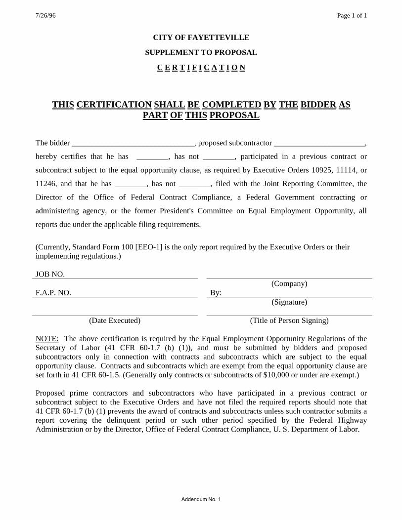
CITY OF FAYETTEVILLE
SUPPLEMENT TO PROPOSAL
C E R T I F I C A T I O N
THIS CERTIFICATION SHALL BE COMPLETED BY THE BIDDER AS PART OF THIS PROPOSAL
The bidder _______________________________, proposed subcontractor _______________________,
hereby certifies that he has ________, has not ________, participated in a previous contract or
subcontract subject to the equal opportunity clause, as required by Executive Orders 10925, 11114, or
11246, and that he has ________, has not ________, filed with the Joint Reporting Committee, the
Director of the Office of Federal Contract Compliance, a Federal Government contracting or
administering agency, or the former President's Committee on Equal Employment Opportunity, all
reports due under the applicable filing requirements.
(Currently, Standard Form 100 [EEO-1] is the only report required by the Executive Orders or their implementing regulations.) JOB NO. (Company) F.A.P. NO. By: (Signature)
(Date Executed) (Title of Person Signing) NOTE: The above certification is required by the Equal Employment Opportunity Regulations of the Secretary of Labor (41 CFR 60-1.7 (b) (1)), and must be submitted by bidders and proposed subcontractors only in connection with contracts and subcontracts which are subject to the equal opportunity clause. Contracts and subcontracts which are exempt from the equal opportunity clause are set forth in 41 CFR 60-1.5. (Generally only contracts or subcontracts of $10,000 or under are exempt.) Proposed prime contractors and subcontractors who have participated in a previous contract or subcontract subject to the Executive Orders and have not filed the required reports should note that 41 CFR 60-1.7 (b) (1) prevents the award of contracts and subcontracts unless such contractor submits a report covering the delinquent period or such other period specified by the Federal Highway Administration or by the Director, Office of Federal Contract Compliance, U. S. Department of Labor.
Addendum No. 1
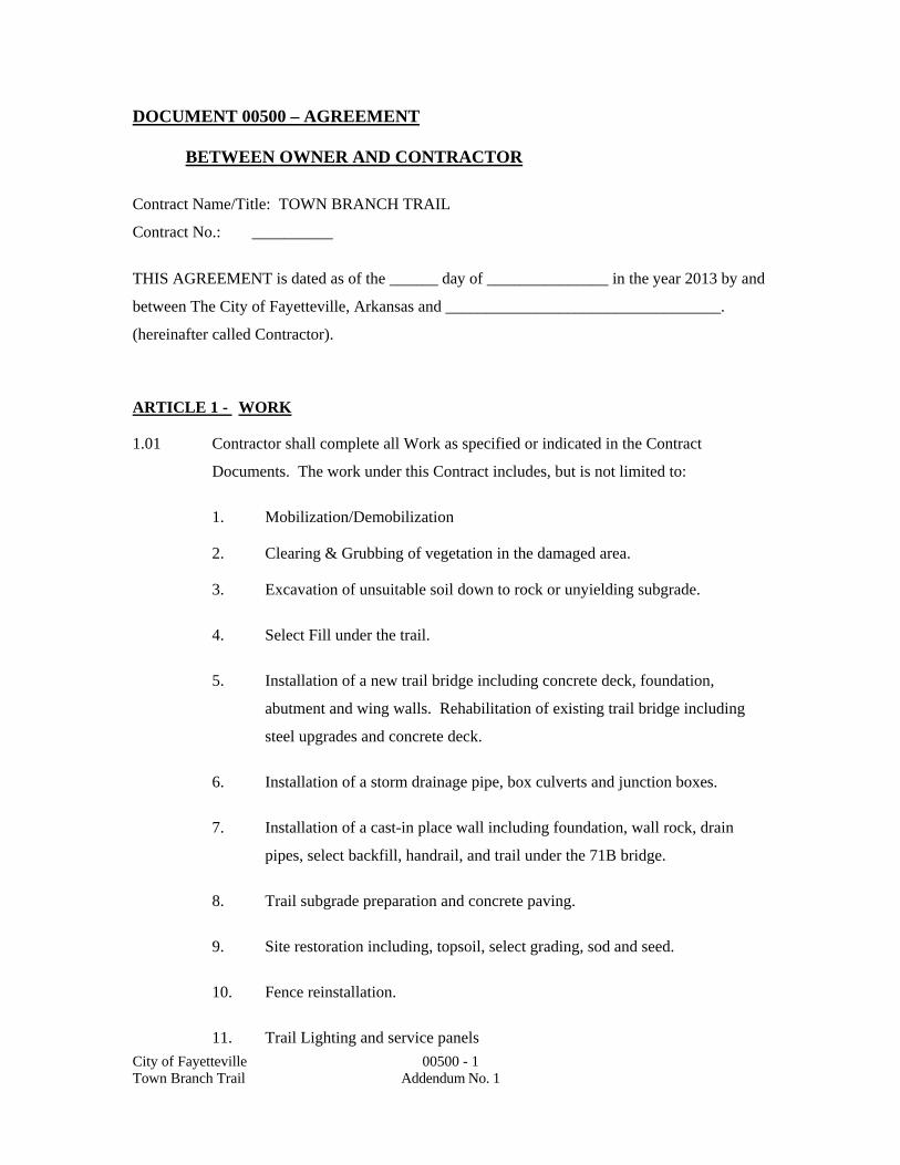
DOCUMENT 00500 – AGREEMENT
City of Fayetteville 00500 - 1 Town Branch Trail Addendum No. 1
BETWEEN OWNER AND CONTRACTOR
Contract Name/Title: TOWN BRANCH TRAIL
Contract No.: __________
THIS AGREEMENT is dated as of the ______ day of _______________ in the year 2013 by and
between The City of Fayetteville, Arkansas and __________________________________.
(hereinafter called Contractor).
ARTICLE 1 - WORK
1.01 Contractor shall complete all Work as specified or indicated in the Contract
Documents. The work under this Contract includes, but is not limited to:
1. Mobilization/Demobilization
2. Clearing & Grubbing of vegetation in the damaged area.
3. Excavation of unsuitable soil down to rock or unyielding subgrade.
4. Select Fill under the trail.
5. Installation of a new trail bridge including concrete deck, foundation,
abutment and wing walls. Rehabilitation of existing trail bridge including
steel upgrades and concrete deck.
6. Installation of a storm drainage pipe, box culverts and junction boxes.
7. Installation of a cast-in place wall including foundation, wall rock, drain
pipes, select backfill, handrail, and trail under the 71B bridge.
8. Trail subgrade preparation and concrete paving.
9. Site restoration including, topsoil, select grading, sod and seed.
10. Fence reinstallation.
11. Trail Lighting and service panels
DOCUMENT 00500 – AGREEMENT (continued)
City of Fayetteville 00500 - 2 Town Branch Trail Addendum No. 1
ARTICLE 2 - ENGINEER
2.01 The Project has been designed by the City of Fayetteville, Engineering Division, who
is hereinafter called Engineer. The Engineer assumes all duties and responsibilities,
and has the rights and authority assigned to Engineer in the Contract Documents in
connection with completion of the Work in accordance with the Contract Documents.
ARTICLE 3 - CONTRACT TIME
3.01 TIME OF THE ESSENCE:
A. All time limits for milestones, if any, Substantial Completion, and
completion and readiness for final payment as stated in the Contract
Documents are of the essence of the Contract.
3.02 DATES FOR SUBSTANTIAL COMPLETION AND FINAL PAYMENT:
A. The Work will be Substantially Completed within 150 calendar days after the
date when the Contract Times commence to run as provided in the
GENERAL CONDITIONS, and completed and ready for final payment in
accordance with the GENERAL CONDITIONS within 180 calendar days
after the date when the Contract Times commence to run.
3.03 LIQUIDATED DAMAGES:
A. Owner and Contractor recognize that time is of the essence of this
Agreement and that The City of Fayetteville will suffer financial loss if the
Work is not completed within the time specified above, plus any extensions
thereof allowed in accordance with the GENERAL CONDITIONS. The
parties also recognize the delays, expense, and difficulties involved in
proving the actual loss suffered by The City of Fayetteville if the Work is not
Substantially Completed on time. Accordingly, instead of requiring any such
proof, The City of Fayetteville and Contractor agree that as liquidated
damages for delay (but not as a penalty) Contractor shall pay The City of
Fayetteville Two Hundred Dollars ($200.00) for each calendar day that
expires after the time specified above in Paragraph 3.02 for Substantial
DOCUMENT 00500 – AGREEMENT (continued)
City of Fayetteville 00500 - 3 Town Branch Trail Addendum No. 1
Completion until the Work is Substantially Complete. After Substantial
Completion, if Contractor shall neglect, refuse, or fail to complete the
remaining Work within the time specified in Paragraph 3.02 for completion
and readiness for final payment or any proper extension thereof granted by
The City of Fayetteville, Contractor shall pay The City of Fayetteville Two
Hundred Dollars ($200.00) for each calendar day that expires after the time
specified for completion and readiness for final payment.
ARTICLE 4 - CONTRACT PRICE
4.01 The CITY OF FAYETTEVILLE agrees to pay, and the CONTRACTOR agrees to
accept, as full and final compensation for all work done under this agreement, the
amount based on the prices bid in the Proposal (BID FORM) which is hereto
attached, for the actual amount accomplished under each pay item, said payments to
be made in lawful money of the United States at the time and in the manner set forth
in the Specifications.
4.02 As provided in the General Conditions estimated quantities are not guaranteed, and
determinations of actual quantities and classifications are to be made by ENGINEER
as provided in the General Conditions. Unit prices have been computed as provided
in the General Conditions.
4.03 Changes, modifications, or amendments in scope, price or fees to this contract shall
not be allowed without a prior formal contract amendment approved by the Mayor
and the City Council in advance of the change in scope, cost or fees.
ARTICLE 5 - PAYMENT PROCEDURES
5.01 SUBMITTAL AND PROCESSING OF PAYMENTS:
A. Contractor shall submit Applications for Payment in accordance with the
GENERAL CONDITIONS. Applications for Payment will be processed by
Engineer as provided in the GENERAL CONDITIONS.

DOCUMENT 00500 – AGREEMENT (continued)
City of Fayetteville 00500 - 4 Town Branch Trail Addendum No. 1
5.02 PROGRESS PAYMENTS, RETAINAGE:
A. The City of Fayetteville shall make progress payments on account of the
Contract Price on the basis of Contractor's Applications for Payment as
recommended by Engineer, on or about the 15th day of each month during
construction. All such payments will be measured by the schedule of values
established in the GENERAL CONDITIONS (and in the case of Unit Price
Work based on the number of units completed) or, in the event there is no
schedule of values, as provided in the General Requirements.
1. Prior to Substantial Completion, progress payments will be made in an
amount equal to the percentage indicated below, but, in each case, less the
aggregate of payments previously made and less such amounts as Engineer
shall determine, or The City of Fayetteville may withhold, in accordance
with the GENERAL CONDITIONS.
a. 90% of Work Completed (with the balance being retainage). If
Work has been 50% completed as determined by Engineer, and
if the character and progress of the Work have been satisfactory
to The City of Fayetteville and Engineer, The City of
Fayetteville on recommendation of Engineer, may determine that
as long as the character and progress of the Work subsequently
remain satisfactory to them, there will be no additional retainage
on account of Work subsequently completed, in which case the
remaining progress payments prior to Substantial Completion
will be an amount equal to 100% of the Work Completed less the
aggregate of payments previously made; and
b. 100% of Equipment and Materials not incorporated in the Work
but delivered, suitably stored, and accompanied by
documentation satisfactory to The City of Fayetteville as
provided in the GENERAL CONDITIONS.

DOCUMENT 00500 – AGREEMENT (continued)
City of Fayetteville 00500 - 5 Town Branch Trail Addendum No. 1
2. Upon Substantial Completion, The City of Fayetteville shall pay an amount
sufficient to increase total payments to Contractor to 95% of the Contract
Price (with the balance being retainage), less such amounts as Engineer shall
determine, or The City of Fayetteville may withhold, in accordance with the
GENERAL CONDITIONS.
5.03 FINAL PAYMENT:
A. Upon final completion and acceptance of the Work in accordance with the
GENERAL CONDITIONS, The City of Fayetteville shall pay the remainder
of the Contract Price as recommended by Engineer and as provided in the
GENERAL CONDITIONS.
ARTICLE 6 - CONTRACTOR'S REPRESENTATIONS
6.01 In order to induce The City of Fayetteville to enter into this Agreement, Contractor
makes the following representations:
A. Contractor has examined and carefully studied the Contract Documents
including the Addenda and other related data identified in the Bid
Documents.
B. Contractor has visited the Site and become familiar with and is satisfied as to
the general, local, and Site conditions that may affect cost, progress,
performance, and furnishing of the Work.
C. Contractor is familiar with and is satisfied as to all federal, state, and local
Laws and Regulations that may affect cost, progress, performance, and
furnishing of the Work.
D. Contractor has carefully studied all:
(1) reports of explorations and tests of subsurface conditions at or
contiguous to the Site and all drawings of physical conditions in or
relating to existing surface or subsurface structures at or contiguous
to the Site; and
DOCUMENT 00500 – AGREEMENT (continued)
City of Fayetteville 00500 - 6 Town Branch Trail Addendum No. 1
(2) reports and drawings of a Hazardous Environmental Condition, if
any, at the Site. Contractor acknowledges that The City of
Fayetteville and Engineer do not assume responsibility for the
accuracy or completeness of information and data shown or indicated
in the Contract Documents with respect to Underground Facilities at
or contiguous to the Site.
E. Contractor has obtained and carefully studied (or assumes responsibility of
having done so) all such additional supplementary examinations,
investigations, explorations, tests, studies, and data concerning conditions
(surface, subsurface, and Underground Facilities) at or contiguous to the Site
or otherwise which may affect cost, progress, performance, and furnishing of
the Work or which relate to any aspect of the means, methods, techniques,
sequences, and procedures of construction to be employed by Contractor and
safety precautions and programs incident thereto.
F. Contractor does not consider that any additional examinations,
investigations, explorations, tests, studies, or data are necessary for the
performing and furnishing of the Work at the Contract Price, within the
Contract Times, and in accordance with the other terms and conditions of the
Contract Documents.
G. Contractor is aware of the general nature of work to be performed by The
City of Fayetteville and others at the Site that relates to the Work as indicated
in the Contract Documents.
H. Contractor has correlated the information known to Contractor, information
and observations obtained from visits to the Site, reports and drawings
identified in the Contract Documents, and all additional examinations,
investigations, explorations, tests, studies, and data with the Contract
Documents.
I. Contractor has given Engineer written notice of all conflicts, errors,
ambiguities, or discrepancies that Contractor has discovered in the Contract
DOCUMENT 00500 – AGREEMENT (continued)
City of Fayetteville 00500 - 7 Town Branch Trail Addendum No. 1
Documents and the written resolution thereof by Engineer is acceptable to
Contractor.
J. The Contract Documents are generally sufficient to indicate and convey
understanding of all terms and conditions for performance and furnishing of
the Work.
ARTICLE 7 - CONTRACT DOCUMENTS
7.01 CONTENTS:
A. The Contract Documents which comprise the entire Agreement between The
City of Fayetteville and Contractor concerning the Work consist of the
following and may only be amended, modified, or supplemented as provided
in the GENERAL CONDITIONS:
1. This Agreement.
2. Exhibits to this Agreement (enumerated as follows):
a. Notice to Proceed.
b. Contractor's Bid.
c. Documentation submitted by Contractor prior to Notice of
Award.
3. Performance, Payment, and other Bonds.
4. General Conditions.
5. Supplementary Conditions.
6. Specifications consisting of divisions and sections as listed in table of
contents of Project Manual.
DOCUMENT 00500 – AGREEMENT (continued)
City of Fayetteville 00500 - 8 Town Branch Trail Addendum No. 1
7. Drawings consisting of a cover sheet and sheets as listed in the table of
contents thereof, with each sheet bearing the following general title:
TOWN BRANCH TRAIL
8. The following which may be delivered or issued after the Effective Date of
the Agreement and are not attached hereto: All Written Amendments and
other documents amending, modifying, or supplementing the Contract
Documents pursuant to the GENERAL CONDITIONS.
ARTICLE 8 - MISCELLANEOUS
8.01 TERMS:
A. Terms used in this Agreement which are defined in the GENERAL
CONDITIONS shall have the meanings stated in the GENERAL
CONDITIONS.
8.02 ASSIGNMENT OF CONTRACT:
A. No assignment by a party hereto of any rights under or interests in the
Contract Documents will be binding on another party hereto without the
written consent of the party sought to be bound; and specifically but without
limitation, moneys that may become due and moneys that are due may not be
assigned without such consent (except to the extent that the effect of this
restriction may be limited by Law), and unless specifically stated to the
contrary in any written consent to an assignment, no assignment will release
or discharge the assignor from any duty or responsibility under the Contract
Documents.
8.03 SUCCESSORS AND ASSIGNS:
A. The City of Fayetteville and Contractor each binds himself, his partners,
successors, assigns, and legal representatives to the other party hereto, its
partners, successors, assigns, and legal representatives in respect to all
covenants, agreements, and obligations contained in the Contract Documents.

DOCUMENT 00500 – AGREEMENT (continued)
City of Fayetteville 00500 - 9 Town Branch Trail Addendum No. 1
8.04 SEVERABILITY:
A. Any provision or part of the Contract Documents held to be void or
unenforceable under any Law or Regulation shall be deemed stricken, and all
remaining provisions shall continue to be valid and binding upon The City of
Fayetteville and Contractor, who agree that the Contract Documents shall be
reformed to replace such stricken provision or part thereof with a valid and
enforceable provision that comes as close as possible to expressing the
intention of the stricken provision.
8.05 FREEDOM OF INFORMATION ACT:
A. City contracts and documents prepared while performing city contractual
work are subject to the Arkansas Freedom of Information Act. If a Freedom
of Information Act request is presented to the City of Fayetteville, the
contractor will do everything possible to provide the documents in a prompt
and timely manner as prescribed in the Arkansas Freedom of Information Act
(A.C.A. §25-19-101 et. seq.). Only legally authorized photocopying costs
pursuant to the FOIA may be assessed for this compliance.
OTHER PROVISIONS: Not Applicable.
IN WITNESS WHEREOF, The City of Fayetteville and Contractor have signed this Agreement
in quadruplicate. One counterpart each has been delivered to Contractor and Engineer. Two
counterparts each has been delivered to The City of Fayetteville. All portions of the Contract
Documents have been signed, initialed, or identified by The City of Fayetteville and Contractor or
identified by Engineer on their behalf.

DOCUMENT 00500 – AGREEMENT (continued)
City of Fayetteville 00500 - 10 Town Branch Trail Addendum No. 1
This Agreement will be effective on ____________________________, 20__, which is the
Effective Date of the Agreement.
CITY OF FAYETTEVILLE
Name Written: Name Written: Lioneld Jordan
Signature: Signature:
Title: Title: Mayor
(SEAL) (SEAL)
Attest Attest

DOCUMENT 00500 – AGREEMENT (continued)
City of Fayetteville 00500 - 11 Town Branch Trail Addendum No. 1
Address for giving notices Address for giving notices
113 W. Mountain Street
Fayetteville AR, 72701
License No. ___________ (attach evidence of authority to
sign and resolution or other documents
Agent for Service of process authorizing execution of Agreement)
(If Contractor is a corporation, Approved As to Form:
attach evidence of authority to
sign.) By:
Attorney For:
END OF DOCUMENT 00500

DOCUMENT 00550 – NOTICE TO PROCEED
00550 Notice to Proceed 00550-1 Job 040603 Town Branch Trail Addendum No. 1
TO: _______________________________________ (Contractor)
_______________________________________
_______________________________________
_______________________________________
Contract Name/Title: TOWN BRANCH TRAIL – S. SCHOOL AVE. TO GREATHOUSE PARK
Contract No: _____________________________________________
Owner: City of Fayetteville, Arkansas
You are notified that the Contract Time(s) under the above Contract will commence to run on
_____________________________, 20___. By that date, you are to start performing your obligations
under the Contract Documents. In accordance with the Agreement Between Owner and Contractor, the
date(s) of Substantial Completion and final completion ready for final payment are
______________________________, 20___ and __________________________, 20__, respectively.
Before you may start any work at the Site, the General Conditions provide that you and Owner must each
deliver to the other, (with copies to Engineer and other identified additional insureds) certificates of
insurance, which each is required to purchase and maintain in accordance with the Contract Documents.
Also before you may start any work at the Site, you must submit the following:
1. Preliminary construction progress schedule.
2. Preliminary schedule of Submittals.
3. Satisfactory evidence of insurance in accordance with the requirements of the General
Conditions.
4. Temporary erosion control requireiments as specified.
5. Maintenance of Traffic as specified.
You are required to return an acknowledgement copy of this Notice to Proceed to the Owner.
Dated this __________ day of _________________________, 20___.
OWNER

DOCUMENT 00550 - NOTICE TO PROCEED: (continued)
00550 Notice to Proceed 00550-2 Job 040603 Town Branch Trail Addendum No. 1
__________________________________
By _______________________________
Title______________________________
ACCEPTANCE OF NOTICE TO PROCEED
CONTRACTOR
__________________________________
By _______________________________
Title______________________________
Date ____________________, 20_______
Copy to Engineer
(Use Certified Mail,
Return Receipt Requested)
END OF DOCUMENT 00550

DOCUMENT 00610 – PERFORMANCE BOND:
00610 Performance Bond 00610 - 1 Job 040603 Town Branch Trail Addendum No. 1
KNOW ALL MEN BY THESE PRESENTS: that
as Principal, hereinafter called Contractor, and
as Surety, hereinafter called Surety, are held and firmly bound unto
City of Fayetteville, Arkansas
113 West Mountain Street
Fayetteville, Arkansas 72701
as Obligee, hereinafter called Owner, in the amount of __________________________________ Dollars
($_______________), for the payment whereof Contractor and Surety bind themselves, their heirs,
executors, administrators, successors and assigns, jointly and severally, firmly by these presents.
WHEREAS, Contractor has by written Agreement dated __________, 20___, entered into a contract with
Owner for TOWN BRANCH TRAIL – S. SCHOOL AVE. TO GREATHOUSE PARK which
contract is by reference made a part hereof, and is hereinafter referred to as the Contract.
NOW, THEREFORE, THE CONDITION OF THIS OBLIGATION is such that, if Contractor shall
promptly and faithfully perform said Contract, then this obligation shall be null and void; otherwise it
shall remain in full force and effect.
The Surety hereby waives notice of any alteration or extension of time made by the Owner.
Whenever Contractor shall be, and declared by Owner to be in default under the Contract, the Owner
having performed Owner's obligations, thereunder, the Surety may promptly remedy the default, or shall
promptly:

DOCUMENT 00610 – PERFORMANCE BOND: (continued)
00610 Performance Bond 00610 - 2 Job 040603 Town Branch Trail Addendum No. 1
A. Complete the Contract in accordance with its terms and conditions, or
B. Obtain a bid or bids for completing the Contract in accordance with its terms and conditions,
and upon determination by Surety of the lowest responsible bidder, or, if the Owner elects,
upon determination by the Owner and the Surety jointly of the lowest responsible bidder,
arrange for a contract between such bidder and Owner, and make available as Work
progresses (even though there should be a default or a succession of defaults under the
contract or contracts of completion arranged under this paragraph) sufficient funds to pay the
cost of completion less the balance of the Contract Price; but not exceeding, including other
costs and damages for which the Surety may be liable hereunder, the amount set forth in the
first paragraph hereof. The term "balance of the Contract Price," as used in this paragraph,
shall mean the total amount payable by Owner to Contractor under the Contract and any
amendments thereto, less the amount properly paid by Owner to Contractor.
Any suit under this Bond must be instituted before the expiration of two years from the date on which
final payment under the Contract falls due.
No right of action shall accrue on this Bond to or for the use of any person or corporation other than the
Owner named herein or the heirs, executors, administrators, or successors of the Owner.
Signed and sealed this _______ day of ____________ 20___.
CONTRACTOR (CORPORATE SEAL)
By

DOCUMENT 00610 – PERFORMANCE BOND: (continued)
00610 Performance Bond 00610 - 3 Job 040603 Town Branch Trail Addendum No. 1
SURETY COUNTERSIGNED:
By By
ATTORNEY-IN-FACT (CORPORATE SEAL)
(This Bond shall be accompanied with Attorney-in-Fact's authority from Surety)
Approved as to Form:
Attorney for
END OF DOCUMENT 00610

DOCUMENT 00611 – LABOR AND MATERIAL PAYMENT BOND:
00611 Labor and Material Payment Bond 00611 - 1 Job 040603 Town Branch Trail Addendum No. 1
This Bond is issued simultaneously with Performance Bond in favor of Owner conditioned on the full and
faithful performance of the Contract.
KNOW ALL MEN BY THESE PRESENTS: that
as Principal, hereinafter called Contractor, and
as Surety, hereinafter called Surety, are held and firmly bound unto
City of Fayetteville, Arkansas
113 West Mountain Street
Fayetteville, Arkansas 72701
as Obligee, hereinafter called Owner, for the use and benefit of claimants as hereinbelow defined, in the
amount of_____________________________________________________________________Dollars
($_______________), for the payment whereof Principal and Surety bind themselves, their heirs,
executors, administrators, successors and assigns, jointly and severally, firmly by these presents.
WHEREAS, Contractor has by written Agreement dated __________, 20___, entered into a contract with
Owner for TOWN BRANCH TRAIL – S. SCHOOL AVE. TO GREATHOUSE PARK which
contract is by reference made a part hereof, and is hereinafter referred to as the Contract.
NOW, THEREFORE, THE CONDITION OF THIS OBLIGATION is such that, if Contractor shall
promptly make payment to all claimants as hereinafter defined, for all labor and material used or
DOCUMENT 00611 – LABOR AND MATERIAL PAYMENT BOND: (continued)
00611 Labor and Material Payment Bond 00611 - 2 Job 040603 Town Branch Trail Addendum No. 1
reasonably required for use in the performance of the Contract, then this obligation shall be void;
otherwise it shall remain in full force and effect, subject, however, to the following conditions:
A. A claimant is defined as one having a direct contract with the Contractor or with a
Subcontractor of the Contractor for labor, material, or both, used or reasonably required for
use in the performance of the Contract, labor and material being construed to include that part
of water, gas, power, light, heat, oil, gasoline, telephone service, or rental of equipment
directly applicable to the Contract.
B. The above named Contractor and Surety hereby jointly and severally agree with the Owner
that every claimant as herein defined, who has not been paid in full before the expiration of a
period of 90 days after the date on which the last of such claimant's work or labor was done
or performed, or materials were furnished by such claimant, may sue on this Bond for the use
of such claimant, prosecute the suit to final judgment for such sum or sums as may be justly
due claimant, and have execution thereon. The Owner shall not be liable for the payment of
any costs or expenses of any such suit.
C. No suit or action shall be commenced hereunder by any claimant:
1. Unless claimant other than one having a direct contract with Principal, shall have
given written notice to any two of the following: the Contractor, the Owner, or the
Surety within 90 days after such claimant did or performed the last of the work or
labor, or furnished the last of the materials for which said claim is made, stating with
substantial accuracy the amount claimed and the name of the party to whom the
materials were furnished, or for whom the work or labor was done or performed.
Such notice shall be served by mailing the same by registered mail or certified mail,
postage prepaid, in an envelope addressed to Contractor, Owner or Surety, at any
place where an office is regularly maintained for the transaction of business, or
served in any manner in which legal process may be served in the state in which the
aforesaid Project is located, save that such service need not be made by a public
officer.
2. After the expiration of one year following the date on which Contractor ceased Work
on the Contract, it being understood, however, that if any limitation embodied in this

DOCUMENT 00611 – LABOR AND MATERIAL PAYMENT BOND: (continued)
00611 Labor and Material Payment Bond 00611 - 3 Job 040603 Town Branch Trail Addendum No. 1
Bond is prohibited by any Law controlling the construction hereof, such limitation
shall be deemed to be amended so as to be equal to the minimum period of limitation
permitted by such Law.
3. Other than in a state court of competent jurisdiction in and for the county or other
political subdivision of the state in which the Project, or any part thereof, is situated,
or in the United States District Court for the district in which the Project, or any part
thereof, is situated, and not elsewhere.
D. The amount of this Bond shall be reduced by and to the extent of any payment or payments
made in good faith hereunder, inclusive of the payment by Surety of mechanics' liens which
may be filed of record against said improvement, whether or not claim for the amount of such
lien be presented under and against this Bond.
Signed and sealed this _______ day of ____________ 20___.
CONTRACTOR (CORPORATE SEAL)
By
SURETY COUNTERSIGNED:
By By

DOCUMENT 00611 – LABOR AND MATERIAL PAYMENT BOND: (continued)
00611 Labor and Material Payment Bond 00611 - 4 Job 040603 Town Branch Trail Addendum No. 1
ATTORNEY-IN-FACT (CORPORATE SEAL)
(This Bond shall be accompanied with Attorney-in-Fact's authority from Surety)
Approved as to Form:
Attorney for
END OF DOCUMENT 00611

SP-3 Prefabricated Pedestrian Bridge SP-3-1 Garver Project No. 11047130 Town Branch Trail Project Addendum No. 1
SECTION SP-3 PREFABRICATED PEDESTRIAN BRIDGE
DESCRIPTION SP-3-1.1 This item shall consist of all labor, tools, equipment and materials necessary for the design and construction of the prefabricated, pedestrian bridge. This specification is for a fully engineered clear span bridge of steel construction and shall be regarded as minimum standards for design and construction.
QUALIFIED SUPPLIERS SP-3-2.1 Each bidder is required to identify their intended bridge supplier as part of the bid submittal. Qualified suppliers must have at least 5 years experience fabricating these type structures and shall be certified as an AISC Major Bridge Fabricator.
Pre-approved Manufacturers: CONTECH Bridge Solutions Inc. Big R Bridge 8301 State Highway 29 North 650 Justice Lane Alexandria, Minnesota 56308 Mansfield, TX 76063 1-800-328-2047 1-817-788-9118 Wheeler, LLC Excel Bridge Manufacturing, Co. 9330 James Ave. S. 2001 Shoemaker Ave Bloomington, MN 55431 Santa Fe Springs, CA 90670 1-800-328-3986 1-800-548-0054
Suppliers other than those listed above may be used provided the engineer or owner's agent evaluates the proposed supplier and approves the supplier 5 days prior to bid. The contractor must provide the following documentation, for any proposed supplier who is not pre-approved, at least 10 days prior to bid:
Product Literature Representative design calculations Representative drawings Splicing and erection procedures Warranty information Inspection and Maintenance procedures AISC Shop Certification Welder Qualifications
Proposed suppliers must have at least five (5) years experience designing and fabricating these type structures and a minimum of five (5) successful bridge projects, of similar construction, each of which has been in service at least three (3) years. List the location, bridge size, owner, and a contact for reference for each project. The engineer will evaluate and verify the accuracy of the submittal prior to bid. If the engineer determines that the qualifying criteria have not been met, the contractor's proposed supplier shall be rejected. The engineer's ruling shall be final.
SP-3 Prefabricated Pedestrian Bridge SP-3-2 Garver Project No. 11047130 Town Branch Trail Project Addendum No. 1
GENERAL FEATURES OF DESIGN SP-3-3.1 The Bridge span shall be 54'-0" (straight line dimension) and shall be as measured from CL joint at begin bridge to CL joint at end bridge. Bridge width shall be 12'-0" and shall be as measured from the inside face of the safety railing elements. The bridge shall be designed as a Bowstring truss. The bridge shall be designed utilizing an underhung floor beam (top of floor beam welded to the bottom of the bottom chord) or be designed utilizing an H-Section configuration where the floor beams are placed up inside the trusses and attached to the truss verticals. The manufacturer shall maintain the distance from top of deck to bearing seat shown on the construction drawings. The top of the top chord shall not be less than 54 inches above the deck. SP-3-3.2 Member Components All members of the vertical trusses (top and bottom chords, verticals, and diagonals) shall be fabricated from square and/or rectangular structural steel tubing. Other structural members and bracing shall be fabricated from structural steel shapes or square and rectangular structural steel tubing. Unless the floor and fastenings are specifically designed to provide adequate lateral support to the top flange of open shape stringers (w-shapes or channels), a minimum of one stiffener shall be provided in each stringer at every floor beam location.
ATTACHMENTS SP-3-4.1 Safety Rails Vertical safety rails or pickets shall be placed on the structure to a minimum height of 4'-6" above the deck surface. The pickets shall be spaced so as to prevent a 4" sphere from passing through the truss. Pickets shall be placed on the inside of the structure. The picket safety system shall be designed for an infill loading of 200 pounds, applied horizontally at right angles, to a one square foot area at any point in the system. Pickets shall be fabricated to be plumb in the finished condition, not perpendicular to the bottom chord.
SP-3-4.2 Toe Plate The bridge shall be supplied with a steel toe plate mounted to the inside face of both trusses. The toe plate shall be a minimum of 4 inches high. Toe plating will be welded to the truss members at a height adequate to provide a 2 gap between the bottom of the plate and the top of the deck or the top of the bottom chord, whichever is higher. The span of unstiffened flat toe plating (from center to center of supports) shall not exceed 5-8.
SP-3-4.3 Camber The bridge shall have a vertical camber dimension at midspan equal to 100% of the full dead load deflection.
ENGINEERING AND DESIGN LOADING
SP-3 Prefabricated Pedestrian Bridge SP-3-3 Garver Project No. 11047130 Town Branch Trail Project Addendum No. 1
SP-3-5.1 Structural design of the bridge structure(s) shall be performed by or under the direct supervision of a Licensed Professional Engineer and done in accordance with recognized engineering practices and principles. The design of the bridge shall conform to the requirements of the AASHTO LRFD Guide Specifications for Design of Pedestrian Bridges (2009).
SP-3-5.2 Dead Loads The bridge structure design shall consider its own dead load (superstructure and original decking), as well as the additional loads listed below: SP-3-5.3 Pedestrian Live Load Main Members: Main supporting members, including girders, trusses and arches shall be designed for a pedestrian live load of 90 pounds per square foot of bridge walkway area, with no reduction allowed. The pedestrian live load shall be applied to those areas of the walkway so as to produce maximum stress in the member being designed. Secondary Members: Bridge decks and supporting floor systems, including secondary stringers, floor beams and their connections to main supporting members shall be designed for a live load of 90 pounds per square foot, with no reduction allowed.
SP-3-5.4 Truck Load
A 20,000 pound (AASHTO H-10) four wheeled vehicle shall be used for the truck loading. The wheel loads for this vehicle shall be 2,000 pounds and 8,000 pounds for the front and rear axles, respectively. The wheel loads shall be assumed to be spaced 6 feet apart transversely. The distance between the front and rear axles shall be assumed to be 14 feet. The truck shall be positioned 2 feet from the face of the truss to determine the distribution of loading carried by each truss.
All of the concentrated or wheel loads shall be placed so as to produce the maximum stress in each member being analyzed. Critical stresses need be calculated assuming there is only one vehicle on the bridge at any given time. Assumptions that vehicles only travel down the center of the bridge or that the vehicle load is a uniform line load will not be allowed. A vehicle impact allowance is not required.
SP-3-5.5 Wind Loading The bridge shall be designed for a wind load of 35 pounds per square foot on the full vertical projected area of the bridge as if enclosed. The wind load shall be applied horizontally at right angles to the longitudinal axis of the structure. The wind loading shall be considered both in the design of the lateral load bracing system and in the design of the truss vertical members, floor beams and their connections. The effect of forces tending to overturn structures shall be calculated assuming that the wind direction is at right angles to the longitudinal axis of the structure. In addition, an upward force shall be applied at the windward quarter point of the transverse superstructure width. This force shall be 20 pounds per square foot of deck.
SP-3 Prefabricated Pedestrian Bridge SP-3-4 Garver Project No. 11047130 Town Branch Trail Project Addendum No. 1
SP-3-5.6 Stream Force The bridge shall be designed for a lateral stream force as required by the AASHTO LRFD Bridge Design Specifications (6 Ed.). The stream velocity for the 100 year design storm is 10 fps. Calculation of the stream force shall assume that the bridge structure is completely blocked with debris. SP-3-5.7 Combination of Loading Combinations of loads, allowable stresses for service load design, and load factors for load factored design shall conform to the AASHTO LRFD Guide Specifications for the Design of Pedestrian Bridges (2009).
DESIGN LIMITATIONS
SP-3-6.1 Vertical Deflection The vertical deflection of the main trusses due to service pedestrian live load shall not exceed 1/360 of the span. The vertical deflection of cantilever spans of the structure due to service pedestrian live load shall not exceed 1/220 of the cantilever arm length. The deflection of the floor system members (floor beams and stringers) due to service pedestrian live load shall not exceed 1/360 of their respective spans. The service pedestrian live load shall be 90 PSF. Deflection limits due to occasional vehicular traffic shall not be considered.
SP-3-6.1 Vibration The fundamental frequency shall meet the requirements of the AASHTO LRFD Guide Specifications for the Design of Pedestrian Bridges (2009). SP-3-6.2 Horizontal Deflection The horizontal deflection of the structure due to lateral wind loads shall not exceed 1/500 of the span under a 35 PSF wind load. SP-3-6.3 Minimum Thickness of Metal The minimum thickness of all structural steel members shall be meet the requirements of the AASHTO LRFD Guide Specifications for the Design of Pedestrian Bridges (2009). For ASTM A500 and ASTM A847 tubing, the section properties used for design shall be per the Steel Tube Institute of North America's Hollow Structural Sections "Dimensions and Section Properties".
MATERIALS SP-3-6.1 Unpainted Weathering Steel Bridges shall be fabricated from high strength, low alloy, atmospheric corrosion resistant ASTM A847 cold-formed welded square and rectangular tubing and/or ASTM A588, or ASTM A242, ASTM A606 plate and structural steel shapes (Fy = 50,000 psi). The minimum corrosion index of atmospheric corrosion resistant steel, as determined in accordance with ASTM G101, shall be 6.0.
SP-3 Prefabricated Pedestrian Bridge SP-3-5 Garver Project No. 11047130 Town Branch Trail Project Addendum No. 1
SP-3-6.2 Concrete Deck The bridge shall be furnished with a stay-in-place, non-composite, galvanized steel form deck suitable for pouring a reinforced concrete slab. The form deck shall be designed to carry the dead load of the wet concrete, weight of the form decking, plus a construction load of 20 PSF uniform load or a 200 pound concentrated load on a 1-0 wide section of deck. When edge supports are used, deflection is limited to 1/180 of the span or 3/4, whichever is less. Without edge supports, deflection shall be limited to 1/180 of the span or 3/8, whichever is less. The form deck material shall be supplied in accordance with ASTM A653 and galvanized to a minimum G90 coating weight. The deck slab shall be constructed using Class S(AE) concrete with a minimum 28-day strength of 4000 psi. Concrete deck design shall be performed by the bridge manufacturer. Concrete decks shall be designed for concentrated loads as specified above.
SP-3-6.3 Welding Welding and weld procedure qualification tests shall conform to the provisions of ANSI/AWS D1.1 “Structural Welding Code”, 1996 Edition. Filler metal shall be in accordance with the applicable AWS Filler Metal Specification (i.e. AWS A 5.28 for the GMAW Process). For exposed, bare, unpainted applications of corrosion resistant steels (i.e. ASTM A588 and A847), the filler metal shall be in accordance with AWS D1.1, Section 3.7.3. Welders shall be properly accredited operators, each of whom shall submit certification of satisfactorily passing AWS standard qualification tests for all positions with unlimited thickness of base metal, have a minimum of 6 months experience in welding tubular structures and have demonstrated the ability to make uniform sound welds of the type required.
SUBMITTALS SP-3-7.1 Submittal Drawings Schematic drawings and diagrams shall be submitted to the Engineer for their review after receipt of order. Submittal drawings shall be unique drawings, prepared to illustrate the specific portion of the work to be done. All relative design information such as member sizes, bridge reactions, and general notes shall be clearly specified on the drawings. Drawings shall have cross referenced details and sheet numbers. All drawings shall be signed and sealed by a Professional Engineer who is licensed in accordance with Section 3.0. SP-7-7.2 Structural Calculations Structural calculations for the bridge superstructure shall be submitted by the bridge manufacturer and reviewed by the approving engineer. All calculations shall be signed and sealed by a Professional Engineer who is licensed in accordance with Section 3.0. The calculations shall include all design information necessary to determine the structural adequacy of the bridge. The calculations shall include the following:
All AASHTO LRFD design checks for axial, bending and shear forces in the critical member of

SP-3 Prefabricated Pedestrian Bridge SP-3-6 Garver Project No. 11047130 Town Branch Trail Project Addendum No. 1
each truss member type (i.e. top chord, bottom chord, floor beam, vertical, etc.). Checks for the critical connection failure modes for each truss member type (i.e. vertical,
diagonal, floor beam, etc.). Special attention shall be given to all welded tube on tube connections.
All bolted splice connections. Main truss deflection checks. U-Frame stiffness checks (used to determine K factors for out-of-plane buckling of the top chord)
for all half through or "pony" truss bridges. Deck design.
NOTE: The analysis and design of triangulated truss bridges shall account for moments induced in members due to joint fixity where applicable. Moments due to both truss deflection and joint eccentricity must be considered. Welder certifications in compliance with AWS standard qualification tests. Welding procedures in compliance with Section 5.1.
FABRICATION SP-3-8.1 Drain Holes When the collection of water inside a structural tube is a possibility, either during construction or during service, the tube shall be provided with a drain hole at its lowest point to let water out. SP-3-8.2 Welds Special attention shall be given to developing sufficient weld throats on tubular members. Fillet weld details shall be in accordance with AWS D1.1. Unless determined otherwise by testing, the loss factor “Z” for heel welds shall be in accordance with AWS Table 2.8. Fillet welds which run onto the radius of a tube shall be built up to obtain the full throat thickness. The maximum root openings of fillet welds shall not exceed 3/16” in conformance with AWS D1.1, Section 5.22. Weld size or effective throat dimensions shall be increased in accordance with this same section when applicable (i.e. fit-up gaps> 1/16”).
The fabricator shall have verified that the throat thickness of partial joint penetration groove welds (primarily matched edge welds or the flare-bevel-groove welds on underhung floor beams) shall be obtainable with their fit-up and weld procedures. Matched edge welds shall be “flushed” out when required to obtain the full throat or branch member wall thickness. For full penetration butt welds of tubular members, the backing material shall be fabricated prior to installation in the tube so as to be continuous around the full tube perimeter, including corners. Backing may be of four types:
A “box” welded up from four (4) plates. Two “channel” sections, bent to fit the inside radius of the tube, welded together with full
penetration welds. A smaller tube section which slides inside the spliced tube. A solid plate cut to fit the inside radius of the tube.

SP-3 Prefabricated Pedestrian Bridge SP-3-7 Garver Project No. 11047130 Town Branch Trail Project Addendum No. 1
Corners of the “box” backing, made from four plates, shall be welded and ground to match the inside corner radii of the chords. The solid plate option shall require a weep hole either in the chord wall above the “high side” of the plate or in the plate itself. In all types of backing, the minimum fit-up tolerances for backing must be maintained at the corners of the tubes as well as across the “flats”. SP-3-8.3 Quality Certification Bridge(s) shall be fabricated by a fabricator who is currently certified by the American Institute of Steel Construction to have the personnel, organization, experience, capability, and commitment to produce fabricated structural steel for the category “Major Steel Bridges” as set forth in the AISC Certification Program. Quality control shall be in accordance with procedures outlined for AISC certification. For painted structures, the fabricator must hold a "Sophisticated Paint Endorsement" as set forth in the AISC certification program. Furthermore, the bridge(s) shall be fabricated in a facility owned and/or leased by the corporate owner of the manufacturer, and fully dedicated to bridge manufacturing.
FINISHING SP-3-9.1 Blast Cleaning All Blast Cleaning shall be done in a dedicated OSHA approved indoor facility owned and operated by the bridge fabricator. Blast operations shall use Best Management Practices and exercise environmentally friendly blast media recovery systems. To aid in providing a uniformly “weathered” appearance, all exposed surfaces of steel shall be blast cleaned in accordance with Steel Structures Painting Council Surface Preparation Specifications No. 7 Brush-Off Blast Cleaning, SSPC-SP7 latest edition. Exposed surfaces of steel shall be defined as those surfaces seen from the deck and from outside of the structure. Stringers, floor beams, lower brace diagonals and the inside face of the truss below deck and bottom face of the bottom chord shall not be blasted.
DELIVERY AND ERECTION SP-3-10.1 Delivery is made to a location nearest the site which is easily accessible to normal over-the-road tractor/trailer equipment. All trucks delivering bridge materials will need to be unloaded at the time of arrival. The manufacturer will provide detailed, written instruction in the proper lifting procedures and splicing procedures (if required). The method and sequence of erection shall be the responsibility of others. The bridge manufacturer shall provide written inspection and maintenance procedures to be followed by the bridge owner.
BEARINGS
SP-3-11.1 Bearing Devices

SP-3 Prefabricated Pedestrian Bridge SP-3-8 Garver Project No. 11047130 Town Branch Trail Project Addendum No. 1
The bridge manufacturer shall be responsible for the design and the bearing devices. The manufacturer shall have the option of using steel bearing, elastomeric bearings, or a combination thereof. The bearing devices shall be designed for the anticipated temperature differentials and for the actual rotations of the bearings due to dead and live load rotations. SP-3-11.2 Anchor Bolts Unless specified otherwise, the bridge manufacturer shall determine the number, diameter, minimum grade and finish of all anchor bolts. The anchor bolts shall be designed to resist all horizontal and uplift forces to be transferred by the superstructure to the supporting foundations. Engineering design of the bridge supporting foundations, including design of anchor bolt embedments, shall be the responsibility of the foundation engineer. The contractor shall provide all materials for (including anchor bolts) and construction of the bridge supporting foundations. The contractor shall install the anchor bolts in accordance with the manufacturer's anchor bolt spacing dimensions. Information as to bridge support reactions and anchor bolt locations will be furnished by the bridge manufacturer after receipt of order and after the bridge design is complete.
WARRANTY
SP-3-12.1 The bridge manufacturer shall warrant their steel structure to be free of design, material and workmanship defects for a period of ten years from the date of delivery. This warranty does not include decking, railing attachments, on any other items not part of the steel truss structure. This warranty shall not cover defects in the bridge caused by abuse, misuse, overloading, accident, improper maintenance, alteration or any other cause not the result of defective materials or workmanship. This warranty shall be void unless owner’s records can be supplied which shall indicate compliance with the minimum guidelines specified in the inspection and maintenance procedures. Repair or replacements shall be the exclusive remedy for defects under this warranty. The bridge manufacturer shall not be liable for any consequential or incidental damages for breach of any express or implied warranty on their structures.
MEASUREMENT AND PAYMENT
SP-3-13.1 All materials, equipment, work and labor required for the design and construction of the prefabricated pedestrian bridge shall be measured and paid for on a lump sum basis. The lump sum price shall be full compensation for designing, fabricating, delivering, and erecting the prefabricated bridge. The lump sum price shall also include all labor and materials required for the cast-in-place concrete deck including concrete and reinforcing steel. Payment will be made under: Item SP-2 New Bridge Construction per Lump Sum
END OF SECTION SP-3
SP-5 Retaining Wall Construction SP-5-1 Garver Project No. 11047130 Town Branch Trail Project Addendum No. 1
SECTION SP-5 RETAINING WALL CONSTRUCTION
DESCRIPTION SP-5-1.1 This item shall consist of providing all labor, tools, equipment and materials necessary for the construction of the new retaining wall located underneath and in the vicinity of the existing Hwy. 62 (School Ave.) Bridge.
MATERIALS
SP-5-2.1 Retaining Wall Items: All materials shall meet the requirement of the applicable section of the 2003 Edition of the Arkansas State Highway and Transportation Department’s Standard Specification for Highway Construction and the applicable Special Provisions listed below in Table 1.
TABLE 1
MATERIAL SECTION
Flowable Select Material Section 206 Aggregate Base Course (Class 7) Section 303 Unclassified Excavation for Structures Bridge Section 801 Class S Concrete Bridge Section 802 Reinforcing Steel - Bridge (Grade 60) Section 804 (Modified per SP-5-3.2) Retaining Wall Construction SP-5
GENERAL FEATURES
SP-5-3.1 The proposed retaining wall shall conform to the details and notes shown on the plans. The wall shall follow the indicated horizontal and vertical alignment and shall be constructed of Class S concrete and Grade 60 reinforcing steel. SP-5-3.2 The Contractor shall submit to the Engineer for review three (3) copies of shop drawings detailing all reinforcing steel required for construction of cast-in-place retaining wall.
EXCAVATION SP-5-4.1 The proposed retaining wall will require excavation through the overburden soil layer and into the shale layer as shown on the plans. The top of rock elevation shown on the plans is estimated and the actual bottom of wall footing elevation is subject to change based on field conditions. The plan elevation shall be used as the basis of payment. No adjustment in the lump sum price of the retaining wall will be made. SP-5-4.2 An existing abandoned concrete structure under the existing Hwy. 62 Bridge lies in relative proximity to the proposed wall. The Contractor shall excavate whatever portion of the concrete is necessary to accommodate the new wall construction. SP-5-4.3 The Contractor shall use whatever means necessary to keep the wall excavation dry until completion of the wall.

SP-5 Retaining Wall Construction SP-5-2 Garver Project No. 11047130 Town Branch Trail Project Addendum No. 1
UTILITIES SP-5-6.1 The Contractor shall incorporate the proposed 18" RCP into the wall construction at the location and according to the notes and details shown on the plans. SP-5-6.2 The Contractor shall incorporate the existing 8" +/- dia. water line into the wall construction at the location and according to the notes and details shown on the plans. All necessary measures shall be taken to ensure that the water line remains in service and is not damaged in the course of construction. SP-5-6.3 The Contractor shall temporarily support the water line until the wall excavation is complete and the backfill construction has reached the level of the water line. SP-5-6.4 The Contractor shall protect the existing water line by means of flowable fill material. Limits of flowable fill material shall conform to the details shown on the plans and Section 206 of the Standard Specifications.
BACKFILL SP-5-7.1 The Contractor shall backfill with Class 7 aggregate base course in accordance with Section 303 of the Standard Specifications. The backfill shall be compacted according to Section 303.03.
OVERHEAD BRIDGE DECK DRAINS
SP-5-8.1 The Contractor shall plug the two southern-most bridge deck slot drains (both sides of bridge) in the existing School Ave. bridge to prevent storm water from falling onto the new trail below using Class S (AE) concrete. The limits of the existing slot drains have been estimated from the original construction plans and it is anticipated that four drains will need to be plugged to protect the new trail underpass. SP-5-8.2 The Contractor shall field verify that plugging four drains is sufficient to protect the trail underneath from storm water, and if required, the Contractor shall plug additional slot drains.
MEASUREMENT AND PAYMENT
SP-5-9.1 All materials, equipment, labor, and incidentals required to complete the construction of the proposed retaining wall shall be measured and paid for on a lump sum basis. The Retaining Wall Construction (cast-in-place) item includes all costs of Class S concrete, reinforcing steel, preparation of shop drawings, excavation in the wall area, backfill material, incorporation of new 18" RCP and existing 8" water line, preformed joint material, and all required incidentals shown on the plans. This item also includes the cost to plug existing slot drains in the School Ave. bridge (number to be confirmed in the field by Contractor). Payment will be made under: Item SP-5 Retaining Wall Construction per Lump Sum
END OF SECTION SP-5

SP-12 Raceways and Boxes for Elec. Sys. SP-12-1 Job 040603 Town Branch Trail Addendum No. 1
SECTION SP-12 - RACEWAYS AND BOXES FOR ELECTRICAL SYSTEMS
PART 1 - GENERAL
1.1 RELATED DOCUMENTS
A. General provisions of the Contract, including General and Supplementary Conditions and other Specification Sections or the Project Manual, apply to this Section.
1.2 SUMMARY
A. Section Includes:
1. Metal conduits, tubing, and fittings. 2. Nonmetal conduits, tubing, and fittings. 3. Boxes, enclosures, and cabinets. 4. Handholes and boxes for exterior underground cabling.
B. Related Requirements:
1. Section SP-19 "Underground Ducts and Raceways for Electrical Systems" for exterior ductbanks, manholes, and underground utility construction.
1.3 DEFINITIONS
A. GRC: Galvanized rigid steel conduit.
1.4 ACTION SUBMITTALS
A. Product Data: For surface raceways, wireways and fittings, floor boxes, hinged-cover enclosures, and cabinets.
PART 2 - PRODUCTS
2.1 METAL CONDUITS, TUBING, AND FITTINGS
A. Manufacturers: Subject to compliance with requirements, available manufacturers offering products that may be incorporated into the Work include, but are not limited to, the following or equal:
1. AFC Cable Systems, Inc. 2. Allied Tube & Conduit. 3. Anamet Electrical, Inc.

SP-12 Raceways and Boxes for Elec. Sys. SP-12-2 Job 040603 Town Branch Trail Addendum No. 1
4. Electri-Flex Company. 5. O-Z/Gedney. 6. Picoma Industries. 7. Republic Conduit. 8. Robroy Industries. 9. Southwire Company. 10. Thomas & Betts Corporation. 11. Western Tube and Conduit Corporation. 12. Wheatland Tube Company.
B. Listing and Labeling: Metal conduits, tubing, and fittings shall be listed and labeled as defined in NFPA 70, by a qualified testing agency, and marked for intended location and application.
C. GRC: Comply with ANSI C80.1 and UL 6.
D. PVC-Coated Steel Conduit: PVC-coated rigid steel conduit.
1. Comply with NEMA RN 1. 2. Coating Thickness: 0.040 inch (1 mm), minimum.
E. FMC: Comply with UL 1; zinc-coated steel.
F. LFMC: Flexible steel conduit with PVC jacket and complying with UL 360.
G. Fittings for Metal Conduit: Comply with NEMA FB 1 and UL 514B.
1. Conduit Fittings for Hazardous (Classified) Locations: Comply with UL 886 and NFPA 70.
2. Expansion Fittings: PVC or steel to match conduit type, complying with UL 651, rated for environmental conditions where installed, and including flexible external bonding jumper.
3. Coating for Fittings for PVC-Coated Conduit: Minimum thickness of 0.040 inch (1 mm), with overlapping sleeves protecting threaded joints.
H. Joint Compound for GRC: Approved, as defined in NFPA 70, by authorities having jurisdiction for use in conduit assemblies, and compounded for use to lubricate and protect threaded conduit joints from corrosion and to enhance their conductivity.
2.2 NONMETALLIC CONDUITS, TUBING, AND FITTINGS
A. Manufacturers: Subject to compliance with requirements, available manufacturers offering products that may be incorporated into the Work include, but are not limited to, the following or equal:
1. AFC Cable Systems, Inc. 2. Anamet Electrical, Inc. 3. Arnco Corporation. 4. CANTEX Inc.

SP-12 Raceways and Boxes for Elec. Sys. SP-12-3 Job 040603 Town Branch Trail Addendum No. 1
5. CertainTeed Corporation. 6. Condux International, Inc. 7. Electri-Flex Company. 8. Kraloy. 9. Lamson & Sessions; Carlon Electrical Products. 10. Niedax-Kleinhuis USA, Inc. 11. RACO; Hubbell. 12. Thomas & Betts Corporation.
B. Listing and Labeling: Nonmetallic conduits, tubing, and fittings shall be listed and labeled as defined in NFPA 70, by a qualified testing agency, and marked for intended location and application.
C. ENT: Comply with NEMA TC 13 and UL 1653.
D. RNC: Type EPC-40-PVC, complying with NEMA TC 2 and UL 651 unless otherwise indicated.
E. LFNC: Comply with UL 1660.
F. Rigid HDPE: Comply with UL 651A.
G. Continuous HDPE: Comply with UL 651B.
H. Coilable HDPE: Preassembled with conductors or cables, and complying with ASTM D 3485.
I. RTRC: Comply with UL 1684A and NEMA TC 14.
J. Fittings for ENT and RNC: Comply with NEMA TC 3; match to conduit or tubing type and material.
K. Fittings for LFNC: Comply with UL 514B.
L. Solvent cements and adhesive primers shall have a VOC content of 510 and 550 g/L or less, respectively, when calculated according to 40 CFR 59, Subpart D (EPA Method 24).
M. Solvent cements and adhesive primers shall comply with the testing and product requirements of the California Department of Health Services' "Standard Practice for the Testing of Volatile Organic Emissions from Various Sources Using Small-Scale Environmental Chambers."
2.3 BOXES, ENCLOSURES, AND CABINETS
A. Manufacturers: Subject to compliance with requirements, available manufacturers offering products that may be incorporated into the Work include, but are not limited to, the following or equal:
1. Adalet.

SP-12 Raceways and Boxes for Elec. Sys. SP-12-4 Job 040603 Town Branch Trail Addendum No. 1
2. Cooper Technologies Company; Cooper Crouse-Hinds. 3. EGS/Appleton Electric. 4. Erickson Electrical Equipment Company. 5. FSR Inc. 6. Hoffman. 7. Hubbell Incorporated. 8. Kraloy. 9. Milbank Manufacturing Co. 10. Mono-Systems, Inc. 11. O-Z/Gedney. 12. RACO; Hubbell. 13. Robroy Industries. 14. Spring City Electrical Manufacturing Company. 15. Stahlin Non-Metallic Enclosures. 16. Thomas & Betts Corporation. 17. Wiremold / Legrand.
B. General Requirements for Boxes, Enclosures, and Cabinets: Boxes, enclosures, and cabinets installed in wet locations shall be listed for use in wet locations.
C. Sheet Metal Outlet and Device Boxes: Comply with NEMA OS 1 and UL 514A.
D. Cast-Metal Outlet and Device Boxes: Comply with NEMA FB 1, ferrous alloy, Type FD, with gasketed cover.
E. Small Sheet Metal Pull and Junction Boxes: NEMA OS 1.
F. Cast-Metal Access, Pull, and Junction Boxes: Comply with NEMA FB 1 and UL 1773, galvanized, cast iron with gasketed cover.
G. Hinged-Cover Enclosures: Comply with UL 50 and NEMA 250, Type 3R with continuous-hinge cover with flush latch unless otherwise indicated.
1. Metal Enclosures: Steel, finished inside and out with manufacturer's standard enamel.
H. Cabinets: Metered Commercial Pedestal 1. Voltage rating : 120/240v 1 P 3W, AIC rating: 10, Amperage rating : 100 amps 2. The pedestal shall be of NEMA Type 3R rainproof construction and shall be UL
Listed as "Enclosed Industrial Control Equipment" (UL 508A). External construction shall comply with UL50 requirements and shall be of G90 galvanized steel with light green #14672 Federal Specification 595 polyurethane industrial grade powder paint of 1.7 mil minimum thickness (unless otherwise specified). Aluminum and stainless steel are other factory options available. Internal construction shall be G90 galvanized steel and 1. 7 mil minimum thickness polyurethane industrial grade powder coat painted or bare aluminum. No fasteners except sealing screws shall be removable by external access. Hinges shall be stainless steel and of the continuous piano hinge type. The pedestal mounting bolts shall not be externally accessible.

SP-12 Raceways and Boxes for Elec. Sys. SP-12-5 Job 040603 Town Branch Trail Addendum No. 1
3. The pedestal shall be offered with an optional base designed to be embedded in concrete in place of anchor bolts. Either pedestal mounting base or anchor bolt kit is required for installation.
4. The service pedestal must have three separate isolated sections for metering equipment, utility termination and customer equipment. The metering section must be pad-lockable and sealable and have a hinged swing back hood with an integral hinged polycarbonate sealable window for access to demand meters. An external nameplate shall be permanently attached to the hood. A stainless steel handle shall be provided on the front exterior of the hood. Meter socket type shall meet the requirements of the serving utility.
5. The utility termination section must be pad-lockable and sealable and shall have a stainless steel handle provided on a lift-off cover. Sufficient clearance shall be provided for a 4-inch diameter conduit for utility cables entrance. Utility landing lugs shall be UL listed and shall accommodate #6-350 kcmil conductors.
6. The customer compartment door to be hinged on the left hand side. A stainless pad-lockable hasp provided to secure customer compartment. A door keeper provided to keep the door in an open position. A print pocket on the inside of the door shall hold all wiring schematics, circuit directories and instructions in a clear, weatherproof sleeve. Required UL labeling shall be located on the inside of the customer door. Distribution and control equipment shall be behind an internal dead-front door with a quarter-turn securing latch and be hinged to open more than 90 degrees. The dead-front door shall be hinged on the same side as the customer section door. All distribution and control equipment shall be factory wired using 600 volt wire sized to NEG and UL requirements.
7. The service pedestal shall be rated for operation at 1 OK minimum (AIC) amps interrupting capacity. The provided documentation shall list circuit breaker combinations and those to be used for de-rated operation for series ratings. Circuit breakers shall be permanently labeled with engraved name plates.
8. Utility requirements for this equipment vary. Always consult the serving utility for their requirements before ordering or installing this equipment.
9. Meter Socket shall be heavy duty ringless with manual lever bypass
2.4 HANDHOLES AND BOXES FOR EXTERIOR UNDERGROUND WIRING
A. General Requirements for Handholes and Boxes:
1. Boxes and handholes for use in underground systems shall be designed and identified as defined in NFPA 70, for intended location and application.
2. Boxes installed in wet areas shall be listed and labeled as defined in NFPA 70, by a qualified testing agency, and marked for intended location and application.
B. Polymer-Concrete Handholes and Boxes with Polymer-Concrete Cover: Molded of sand and aggregate, bound together with polymer resin, and reinforced with steel, fiberglass, or a combination of the two. 1. Basis-of-Design Product: Subject to compliance with requirements, provide
product indicated in the Project Manual or comparable product by one of the following or equal:

SP-12 Raceways and Boxes for Elec. Sys. SP-12-6 Job 040603 Town Branch Trail Addendum No. 1
a. Armorcast Products Company. b. Carson Industries LLC. c. NewBasis. d. Oldcastle Precast, Inc. e. Quazite: Hubbell Power System, Inc. f. Synertech Moulded Products.
2. Standard: Comply with SCTE 77. 3. Configuration: Designed for flush burial with closed bottom unless otherwise
indicated. 4. Cover: Weatherproof, secured by tamper-resistant locking devices and having
structural load rating consistent with enclosure and handhole location. 5. Cover Finish: Nonskid finish shall have a minimum coefficient of friction of 0.50. 6. Cover Legend: Molded lettering, "ELECTRIC." 7. Conduit Entrance Provisions: Conduit-terminating fittings shall mate with entering
ducts for secure, fixed installation in enclosure wall. 8. Handholes 12 Inches Wide by 24 Inches Long (300 mm Wide by 600 mm Long)
and Larger: Have inserts for cable racks and pulling-in irons installed before concrete is poured.
C. Fiberglass Handholes and Boxes: Molded of fiberglass-reinforced polyester resin, with frame and covers of polymer concrete. 1. Basis-of-Design Product: Subject to compliance with requirements, provide
product indicated in the Project Manual or comparable product by one of the following or equal:
a. Armorcast Products Company. b. Carson Industries LLC. c. NewBasis. d. Nordic Fiberglass, Inc. e. Oldcastle Precast, Inc; Christy Concrete Products. f. Quazite: Hubbell Power System, Inc; Hubbell Power Systems. g. Synertech Moulded Products.
2. Standard: Comply with SCTE 77. 3. Color of Frame and Cover: Green. 4. Configuration: Designed for flush burial with closed bottom unless otherwise
indicated. 5. Cover: Weatherproof, secured by tamper-resistant locking devices and having
structural load rating consistent with enclosure and handhole location. 6. Cover Finish: Nonskid finish shall have a minimum coefficient of friction of 0.50. 7. Cover Legend: Molded lettering, "ELECTRIC." 8. Conduit Entrance Provisions: Conduit-terminating fittings shall mate with entering
ducts for secure, fixed installation in enclosure wall. 9. Handholes 12 Inches Wide by 24 Inches Long (300 mm Wide by 600 mm Long)
and Larger: Have inserts for cable racks and pulling-in irons installed before concrete is poured.

SP-12 Raceways and Boxes for Elec. Sys. SP-12-7 Job 040603 Town Branch Trail Addendum No. 1
PART 3 - EXECUTION
3.1 RACEWAY APPLICATION
A. Outdoors: Apply raceway products as specified below unless otherwise indicated:
1. Exposed Conduit: GRC 2. Concealed Conduit, Aboveground: GRC 3. Underground Conduit: RNC, Type EPC-40-PVC or Type EPC-80-PVC, direct
buried or concrete encased, as indicated on drawing. 4. Boxes and Enclosures, Aboveground: NEMA 250, Type 3R.
B. Minimum Raceway Size: 3/4-inch (21-mm) trade size.
C. Raceway Fittings: Compatible with raceways and suitable for use and location.
1. Rigid and Intermediate Steel Conduit: Use threaded rigid steel conduit fittings unless otherwise indicated. Comply with NEMA FB 2.10.
2. PVC Externally Coated, Rigid Steel Conduits: Use only fittings listed for use with this type of conduit. Patch and seal all joints, nicks, and scrapes in PVC coating after installing conduits and fittings. Use sealant recommended by fitting manufacturer and apply in thickness and number of coats recommended by manufacturer.
3. Flexible Conduit: Use only fittings listed for use with flexible conduit. Comply with NEMA FB 2.20.
D. Install nonferrous conduit or tubing for circuits operating above 60 Hz. Where aluminum raceways are installed for such circuits and pass through concrete, install in nonmetallic sleeve.
E. Do not install aluminum conduits, boxes, or fittings in contact with concrete or earth.
F. Install surface raceways only where indicated in the Project Manual.
G. Do not install nonmetallic conduit where ambient temperature exceeds 120 deg F (49 deg C)
3.2 INSTALLATION
A. Comply with NECA 1 and NECA 101 for installation requirements except where requirements in the Project Manual or in this article are stricter. Comply with NECA 102 for aluminum conduits. Comply with NFPA 70 limitations for types of raceways allowed in specific occupancies and number of floors.
B. Keep raceways at least 6 inches (150 mm) away from parallel runs of flues and steam or hot-water pipes. Install horizontal raceway runs above water and steam piping.
C. Complete raceway installation before starting conductor installation.
SP-12 Raceways and Boxes for Elec. Sys. SP-12-8 Job 040603 Town Branch Trail Addendum No. 1
D. Comply with requirements in Section SP-17 "Hangers and Supports for Electrical Systems" for hangers and supports.
E. Arrange stub-ups so curved portions of bends are not visible above finished slab.
F. Install no more than the equivalent of three 90-degree bends in any conduit run except for control wiring conduits, for which fewer bends are allowed. Support within 12 inches (300 mm) of changes in direction.
G. Support conduit within 12 inches (300 mm) of enclosures to which attached.
H. Raceways Embedded in Slabs:
1. Run conduit larger than 1-inch (27-mm) trade size, parallel or at right angles to main reinforcement. Where at right angles to reinforcement, place conduit close to slab support. Secure raceways to reinforcement at maximum 10-foot (3-m) intervals.
2. Arrange raceways to cross building expansion joints at right angles with expansion fittings.
3. Arrange raceways to keep a minimum of 1 inch (25 mm) of concrete cover in all directions.
4. Do not embed threadless fittings in concrete unless specifically approved by Architect for each specific location.
5. Change from ENT to PVC-Coated GRC before rising above floor.
I. Threaded Conduit Joints, Exposed to Wet, Damp, Corrosive, or Outdoor Conditions: Apply listed compound to threads of raceway and fittings before making up joints. Follow compound manufacturer's written instructions.
J. Coat field-cut threads on PVC-coated raceway with a corrosion-preventing conductive compound prior to assembly.
K. Terminate threaded conduits into threaded hubs or with locknuts on inside and outside of boxes or cabinets. Install bushings on conduits up to 1-1/4-inch (35mm) trade size and insulated throat metal bushings on 1-1/2-inch (41-mm) trade size and larger conduits terminated with locknuts. Install insulated throat metal grounding bushings on service conduits.
L. Install raceways square to the enclosure and terminate at enclosures with locknuts. Install locknuts hand tight plus 1/4 turn more.
M. Do not rely on locknuts to penetrate nonconductive coatings on enclosures. Remove coatings in the locknut area prior to assembling conduit to enclosure to assure a continuous ground path.
N. Cut conduit perpendicular to the length. For conduits 2-inch (53-mm) trade size and larger, use roll cutter or a guide to make cut straight and perpendicular to the length.
O. Install pull wires in empty raceways. Use polypropylene or monofilament plastic line with not less than 200-lb (90-kg) tensile strength. Leave at least 12 inches (300 mm) of

SP-12 Raceways and Boxes for Elec. Sys. SP-12-9 Job 040603 Town Branch Trail Addendum No. 1
slack at each end of pull wire. Cap underground raceways designated as spare above grade alongside raceways in use.
P. Comply with manufacturer's written instructions for solvent welding RNC and fittings.
Q. Expansion-Joint Fittings:
1. Install in each run of aboveground RNC that is located where environmental temperature change may exceed 30 deg F (17 deg C) and that has straight-run length that exceeds 25 feet (7.6 m). Install in each run of aboveground RMC conduit that is located where environmental temperature change may exceed 100 deg F (55 deg C) and that has straight-run length that exceeds 100 feet (30 m).
2. Install type and quantity of fittings that accommodate temperature change listed for each of the following locations:
a. Outdoor Locations Not Exposed to Direct Sunlight: 125 deg F (70 deg C) temperature change.
b. Outdoor Locations Exposed to Direct Sunlight: 155 deg F (86 deg C) temperature change.
3. Install fitting(s) that provide expansion and contraction for at least 0.00041 inch per foot of length of straight run per deg F (0.06 mm per meter of length of straight run per deg C) of temperature change for PVC conduits. Install fitting(s) that provide expansion and contraction for at least 0.000078 inch per foot of length of straight run per deg F (0.0115 mm per meter of length of straight run per deg C) of temperature change for metal conduits.
4. Install expansion fittings at all locations where conduits cross structure expansion joints.
5. Install each expansion-joint fitting with position, mounting, and piston setting selected according to manufacturer's written instructions for conditions at specific location at time of installation. Install conduit supports to allow for expansion movement.
R. Mount boxes at heights shall be flush with finished grade with priority given to ADA requirements. Install boxes with height measured to bottom of box unless otherwise indicated.
S. Horizontally separate boxes mounted on opposite sides of walls so they are not in the same vertical channel.
T. Locate boxes so that cover or plate will not span different building finishes.
U. Support boxes of three gangs or more from more than one side by spanning two framing members or mounting on brackets specifically designed for the purpose.
V. Fasten junction and pull boxes to or support from building structure. Do not support boxes by conduits.
W. Set metal floor boxes level and flush with finished floor surface.

SP-12 Raceways and Boxes for Elec. Sys. SP-12-10 Job 040603 Town Branch Trail Addendum No. 1
X. Set nonmetallic floor boxes level. Trim after installation to fit flush with finished floor surface.
3.3 INSTALLATION OF UNDERGROUND CONDUIT
A. Direct-Buried Conduit:
1. Excavate trench bottom to provide firm and uniform support for conduit. 2. Install backfill as indicated on the Project Manual. 3. After installing conduit, backfill and compact. Start at tie-in point, and work toward
end of conduit run, leaving conduit at end of run free to move with expansion and contraction as temperature changes during this process. Firmly hand tamp backfill around conduit to provide maximum supporting strength. After placing controlled backfill to within 12 inches (300 mm) of finished grade, make final conduit connection at end of run and complete backfilling with normal compaction.
4. Install manufactured duct elbows for stub-ups at poles and equipment and at building entrances through floor unless otherwise indicated. Encase elbows for stub-up ducts throughout length of elbow.
5. Install manufactured rigid steel conduit elbows for stub-ups at poles and equipment and at building entrances through floor.
a. Couple steel conduits to ducts with adapters designed for this purpose, and encase coupling with 3 inches (75 mm) of concrete for a minimum of 12 inches (300 mm) on each side of the coupling.
b. For stub-ups at equipment mounted on outdoor concrete bases and where conduits penetrate building foundations, extend steel conduit horizontally a minimum of 60 inches (1500 mm) from edge of foundation or equipment base. Install insulated grounding bushings on terminations at equipment.
6. Warning Planks: Bury warning planks approximately 12 inches (300 mm) above direct-buried conduits but a minimum of 6 inches (150 mm) below grade. Align planks along centerline of conduit.
7. Underground Warning Tape: Comply with requirements in Section SP-20 "Identification for Electrical Systems."
3.4 INSTALLATION OF UNDERGROUND HANDHOLES AND BOXES
A. Install handholes and boxes level and plumb and with orientation and depth coordinated with connecting conduits to minimize bends and deflections required for proper entrances.
B. Unless otherwise indicated, support units on a level bed of crushed stone or gravel, graded from 1/2-inch (12.5-mm) sieve to No. 4 (4.75-mm) sieve and compacted to same density as adjacent undisturbed earth.
C. Elevation: In paved areas, set so cover surface will be flush with finished grade. Set covers of other enclosures 1 inch (25 mm) above finished grade.
SP-12 Raceways and Boxes for Elec. Sys. SP-12-11 Job 040603 Town Branch Trail Addendum No. 1
D. Install removable hardware, including pulling eyes, cable stanchions, cable arms, and insulators, as required for installation and support of cables and conductors and as indicated. Select arm lengths to be long enough to provide spare space for future cables but short enough to preserve adequate working clearances in enclosure.
E. Field-cut openings for conduits according to enclosure manufacturer's written instructions. Cut wall of enclosure with a tool designed for material to be cut. Size holes for terminating fittings to be used, and seal around penetrations after fittings are installed.
3.5 PROTECTION
A. Protect coatings, finishes, and cabinets from damage and deterioration.
1. Repair damage to galvanized finishes with zinc-rich paint recommended by manufacturer.
2. Repair damage to PVC coatings or paint finishes with matching touchup coating recommended by manufacturer.
END OF SECTION SP-12

SP-16 Micropiles SP-16-1 Job 040603 Town Branch Trail Project Addendum No. 1
ITEM SP-16 - MICROPILES PART 1 — GENERAL
1-1. SCOPE. This work shall consist of constructing micropiles as indicated on the Drawings and final working drawings and as specified herein. The Contractor is responsible for furnishing of all design, materials, products, accessories, tools, equipment, services, transportation, labor and supervision, and manufacturing techniques required for design, installation and testing of micropiles.
The Contractor shall select the micropile type, size, and determine the required grout bond length and final micropile diameter. The Contractor shall design and install micropiles that will develop the allowable loads indicated on the drawings. The micropile design compressive and tension load capacity shall be verified by testing as required and shall meet the test acceptance criteria specified herein. The Owner or the Owners Engineer will be responsible for pile cap design and connections from the micropile to existing footing.
1-2. MICROPILE CONTRACTOR'S EXPERIENCE REQUIREMENTS.
1-2.01. Micropile Contractor's Experience.
a) Minimum of three projects successfully constructed in the last six years. Micropiles installed based on an end bearing design are not acceptable as project experience.
b) Minimum of at least three projects that involved drilling to install tie-backs or micropiles through manmade fills or native soil that included obstructions such as boulders or concrete pieces using duplex or cased drilling methods.
The Contractor shall assign a supervisor to the work. The supervisor shall have experience on at least three projects of similar scope to this project completed over the past six years. The Contractor shall not use consultants or manufacturers representatives to satisfy the supervisor's requirements of this section. The on-site foremen or superintendent and drill rig operators shall also have experience on at least three projects over the past six years installing micropiles of similar capacity than required herein.
1-2.02. Micropile Designer Experience. The design of the micropiles shall be the responsibility of the micropile subcontractor. The micropiles shall be designed by a licensed professional

SP-16 Micropiles SP-16-2 Job 040603 Town Branch Trail Project Addendum No. 1
engineer. The micropile designer may either be an employee of the micropile subcontractor or a separate consultant designer meeting the stated experience requirement
1-4. DEFINITIONS.
Admixture: Substance added to the grout to control bleed and/or shrinkage, improve flowability, reduce water content, or retard setting time.
Alignment Load (AL): A minimum initial load (5 percent DL maximum) applied to micropile during testing to keep the testing equipment correctly positioned.
Apparent Free Length: The length of pile which is apparently not bonded to the surrounding ground, as calculated from the elastic load extension data during testing.
Bonded Length:
Casing:
Centralizer:
The length of the micropile that is bonded to the ground and which is conceptually used to transfer the applied axial loads to the surrounding soil or bedrock. Also known as the load transfer length.
Steel tube introduced during the drilling process in overburden soil to temporarily stabilize the drill hole. Depending on the details of the micropile construction and composition, this casing may be fully extracted during or after grouting, or may remain partially or completely in place, as part of the final pile configuration.
A device to support and position the reinforcing steel in the center of the drill hole and/or casing so that a minimum grout cover is provided.
Coupler: The means by which load capacity can be transmitted from one partial length of reinforcement to another.
Creep Movement: The movement that occurs during the creep test of a micropile under a constant load.
Design Load (DL): The maximum unfactored load expected to be applied to the micropile during its service life.
SP-16 Micropiles SP-16-3 Job 040603 Town Branch Trail Project Addendum No. 1
Encapsulation: A corrugated or deformed tube protecting the reinforcing steel against corrosion.
Elastic Movement: The recoverable movement measured during a micropile test.
Free (unbonded) Length: The designed length of the micropile that is not bonded to the surrounding ground or rock or grout during testing.
A small diameter bored, cast-in-place composite pile in which the applied load is resisted by steel reinforcement, cement grout, and frictional grout/ground bond. End bearing capacity is ignored. The micropile uses high capacity steel elements, occupying up to 50 percent of the hole volume, as the principle (or sole) load bearing element, with the surrounding grout serving only to transfer, by friction, the applied load between the rock and the steel.
The length that the pile casing is inserted into the grout-toground bond zone.
The injection of additional grout into the load transfer length of a micropile after the primary grout has set. Also known as regrouting or secondary grouting.
The principle whereby load is applied to the micropile, prior to the micropile's connection to the structure, to minimize any structural movement in service.
Portland cement-based grout injected into the micropile hole prior to or after the installation of the reinforcement to provide the load transfer to the surrounding ground along the micropile. . The primary grout also affords a degree of corrosion protection in compression.
Proof Test: Incremental loading of a production micropile, recording the total movement at each increment.
Reinforcement: The steel component of the micropile that accepts and/or resists applied loadings.
Residual Movement: The non-elastic (non-recoverable) movement of a micropile measured during load testing.
Safety Factor: The ratio of the ultimate capacity to the working load used for the design of any component or interface.
Sheathing: Smooth or corrugated piping or tubing that protects the
Micropile:
Plunge Length:
Post-grouting:
Preloading:
Primary Grout:

SP-16 Micropiles SP-16-4 Job 040603 Town Branch Trail Project Addendum No. 1
Single Tube Drilling:
reinforcing steel against corrosion.
The advancement of a steel casing through overburden usually aided by water flushing through the casing. Also known as "external flush." The fluid may or may not return to the surface around the casing, depending largely on the permeability of the overburden.
Spacer: A device to separate elements of a multiple-element reinforcement.
Test Load (TL): The maximum to which the micropile is subjected during testing.
Tremie Grouting: The placing of grout in a borehole via a grout pipe introduced to the bottom of the hole. During grouting, the exit of the pipe is kept at least 10 feet below the level of the grout in the hole.
Type A-D: Classification of micropiles based on method and pressure of grouting (see FHWA, 1997).
Working Drawings Drawings prepared by the Micropile Design Engineer indicating plan and details of micropile construction.
Working Load: Equivalent term for design load.
1-5. AVAILABLE INFORMATION. The geotechnical information available to Contractor from Owner contains the results of exploratory borings obtained in the general vicinity of the proposed micropile locations.
1-6. MICROPILE DESIGN REQUIREMENTS. The micropiles shall be designed to meet the specified loading conditions as provided by the Owner.
The design shall:
a) Ignore the overburden soil contribution to the design load of the micropile.
b) Select the overall length of a micropile such that the required design load is developed by skin friction between grout and bedrock (grout/rock bond) in competent material over a suitable length.
c) Ignore end bearing in determining the design load of the micropile.
d) Base the lateral capacity of the vertical micropiles soil profile contained in the geotechnical report.
SP-16 Micropiles SP-16-5 Job 040603 Town Branch Trail Project Addendum No. 1
The micropiles shall be designed using by AASHTO LRFD BRIDGE DESIGN SPECIFICATIONS, Sixth Edition 2012, with 2013 Interim Revisions, SECTION 10.9 – MICROPILES. The FHWA "Micropile Design and Construction Guidelines Manual," Report No. FHWA-SA-97-070 shall be used for structural design of any individual micropile structure elements not covered in the AASHTO specification. The piles shall be designed for lateral loads as provided by the Owner.
The required geotechnical safety factors/strength factors shall be in accordance with the FHWA manual, unless specified otherwise. Allowable grout/rock bond values and corrosion protection requirements shall be as specified herein.
1-6.01. Micropile Foundation Attachment. The micropile top attachment shall effectively distribute the design load (DL) to the concrete foundation such that the concrete bearing stress does not exceed those in ACI 318 and the bending stress in the steel plates (if used) does not exceed AISC allowable stresses for steel members.
1-6.02. Corrosion Protection. Steel pipe used for micropile permanent casing shall incorporate an additional 1/16 inch thickness of sacrificial steel for corrosion protection. Grout cover on center reinforcing steel shall be a minimum of 0.5 inch in rock. If protective coatings (epoxy, galvanization, or encapsulation) are provided in compression, minimum cover may be 0.25 inch in soil or rock.
1-7. SUBMITTALS. The following information shall be submitted to the Owner in accordance with the submittals section. Work shall not begin until the appropriate submittals have been received and reviewed.
1-7.01. Working Drawings and Design Calculations. Working drawings and relevant structural design calculations for the micropile system or systems intended for use shall be submitted prior to the planned start of construction. All design submittals shall be sealed by a Registered Professional Engineer, licensed in that State. The working drawings shall include notes describing in detail the construction procedures, including an explanation of the drilling, grouting and reinforcing steel placement. The working drawings shall also include:
Micropile identification number, location and pattern
Micropile design load
Casing size Type and size of reinforcing steel
Casing plunge length
Minimum total bond length
Total micropile length
SP-16 Micropiles SP-16-6 Job 040603 Town Branch Trail Project Addendum No. 1
1-7.02. Equipment. A description of major equipment that will be used for installing the pile components.
1-7.03. Structural Steel Drawings. Drawings for all structural steel, including the micropile components, corrosion protection system, pile top attachment and bond length details.
1-7.04. Mill Tests Reports. Certified mill test reports, including ultimate strength, yield strength, elongation, and composition shall be included. For steel pipe used as permanent casing, or core steel, the Contractor shall submit a minimum of two representative coupon tests or mill certifications (if available).
1-7.05. Grout Mix Design. Grout mix designs, including details of all materials to be incorporated, and the procedure for mixing and placing.
1-7.08. Installation Records. The Contractor shall prepare and submit to the Owner, records of the pile installation. The records shall include the following minimum information:
Pile drilling duration and observations (e.g., flush return) Information on soil and rock encountered, including description of strata, water, voids encountered etc.
Approximate Final tip Elevation Cut-off Elevation Design Loads Description of unusual installation behavior, conditions Any deviations from the intended parameters
Grout pressures attained, where applicable Grout quantities pumped (place per each pile) Pile materials and dimensions micropile test records, analysis, and details
SP-16 Micropiles SP-16-7 Job 040603 Town Branch Trail Project Addendum No. 1
PART 2 — PRODUCTS
2-1. MATERIALS. Furnish materials new and without defects. Remove defective materials from the Site at no additional cost to the Owner. Materials for micropiles shall be as follows:
2-1.01. Admixtures for Grout. Admixtures shall conform to the requirements of ASTM C494/AASHTO M194. Admixtures that control bleed, improve flowability, reduce water content, and retard set may be used in the grout. Admixtures shall be compatible with the grout and mixed in accordance with the manufacturer's recommendations. Expansive admixtures shall only be added to the grout used for filling sealed encapsulations and anchorage covers. Accelerators are not permitted. Admixtures containing chlorides are not permitted.
2-1.0.2. Cement, All cement shall be Portland cement conforming to ASTM C150/AASHTO M85, Type I or II.
2-1.03. Centralizers and Spacers. Centralizers and spacers shall be fabricated from schedule 40 PVC pipe or tube, steel, or material non-detrimental to the reinforcing steel. Wood shall not be used. Centralizers and spacers shall be securely attached to the reinforcement; sized to position the reinforcement within 3/8 inch of plan location from center of pile; sized to allow grout tremie pipe insertion to the bottom of the drill hole; and sized to allow grout to freely flow up the drill hole and casing and between adjacent reinforcing bars.
2-1.04. Fine Aggregate. If sand-cement grout is used, sand shall conform to ASTM C144/AASHTO M45.
2-1.05. Grout. Neat cement or sand/cement mixture with a minimum three-day compressive strength of 2,000 psi and a 28-day compressive strength of 5,000 psi per AASHTO T106/ASTM C109.
2-1.06. Grout Protection. Provide a minimum 1 inch grout cover over bare or epoxy- coated bars (excluding bar couplers) or minimum 1/2 inch grout cover over the encapsulation of encapsulated bars.
2-1.07. Permanent Casing Pipe. Permanent steel casing/pipe shall have the diameter and at least minimum wall thickness shown on the approved working drawings. The permanent steel casing/pipe:
2-1.08. Plates and Shapes. Structural steel plates and shapes for pile top attachments shall conform to ASTM A36/AASHTO M183, or ASTM A572/AASHTO M223, Grade 50.

SP-16 Micropiles SP-16-8 Job 040603 Town Branch Trail Project Addendum No. 1
a. Shall meet the Tensile Requirements of ASTM A252, Grade 3, except the yield strength shall be a minimum of 50,000 psi to 75,000 psi as used in the
design submittal. May be new "Structure Grade" (a.k.a. "Mill Secondary") steel pipe meeting above but without mill certification, free from defects (dents,
cracks, tears), and with two coupon tests per truckload delivered to the fabricator.
c. For permanent casing/pipe that will be shop or field welded, the following
fabrication or construction conditions apply:
(1) The steel pipe shall not be joined by welded lap splicing.
(2) Welded seams and splices shall be complete penetration welds.
(3) Partial penetration welds may be restored in conformance with AWS D1.1.
d. Threaded casing joints shall develop at least the required nominal resistance used in the design of the micropile.
2-1.09. Reinforcing Bars. Reinforcing steel shall be deformed bars in accordance with ASTM A615/AASHTO M31, Grade 60 or Grade 75, or ASTM A722/AASHTO M275, Grade 150. Bar tendon couplers, if required, shall develop the ultimate tensile strength of the bars without evidence of any failure.
2-1.10. Water. Water used in the grout mix shall conform to AASHTO T26 and shall be potable, clean, and free from substances that may be injurious to cement and steel.
PART 3 — EXECUTION
3-1. SITE CONTROLS. The Contractor shall control and properly dispose of drill flush and construction-related waste, including excess grout, in accordance with all applicable Laws and Regulations; provide positive control and discharge of all surface water that will affect construction of the micropile installation; and maintain all pipes or conduits used to control surface water during construction. Damage caused by surface water shall be repaired at no additional cost to the Owner. Upon Substantial Completion of the Work, surface water control pipes or conduits shall be removed from the Site.
SP-16 Micropiles SP-16-9 Job 040603 Town Branch Trail Project Addendum No. 1
3-2. TOLERANCES.
a. Centerline of piling shall not be more than 3 inches from indicated final drawing locations.
b. Pile shall be plumb within 2 percent of total-length plan alignment.
c. Top elevation of pile shall be plus 1 inch or minus 1 inches maximum from vertical elevation indicated.
d. Centerline of reinforcing steel shall not be more than 3/4 inch from the indicated location on drawings.
3-3. MICROPILE INSTALLATION The Contractor shall select the grouting procedure, and the grouting pressure used for the installation of the micropiles. The Contractor shall also determine the micropile casing size, final drill hole diameter and bond length, and central tendon reinforcement steel sizing necessary to develop the specified load capacities and load testing requirements. Completed micropiles displaced or damaged by the installation equipment shall be repaired or replaced at no cost to the Owner.
3-3.01. Drilling. The drilling equipment shall be suitable for drilling through the conditions to be encountered, without causing damage to any overlying or adjacent structures or services. Vibratory pile driving hammers shall not be used to advance casing.
3-3.02. Ground Heave or Subsidence. During construction, the Contractor shall observe the conditions in the vicinity of the micropile construction site on a daily basis for signs of ground heave or subsidence. The Contractor shall immediately notify the Owner if signs of movements are observed. Contractor shall immediately suspend or modify drilling or grouting operations if ground heave or subsidence is observed. If the Owner determines that the movements require corrective action, the Contractor shall take corrective actions necessary to stop the movement or perform repairs. When due to the Contractor's methods, operations, or failure to follow the specified/approved construction sequence, the costs of providing corrective actions shall be borne by the Contractor. When due to differing site conditions, the costs of providing corrective actions will be paid as extra Work.
3-3.03 Pipe Casing and Reinforcing Bars Placement and Splicing. Reinforcement may be placed either prior to grouting or placed into the grout-filled drill hole before temporary casing (if used) is withdrawn. Reinforcement surface shall be free of deleterious substances such as soil, mud, grease, or oil that might contaminate the

SP-16 Micropiles SP-16-10 Job 040603 Town Branch Trail Project Addendum No. 1
grout or coat the reinforcement and impair bond.
The Contractor shall check pile top elevations and adjust all installed micropiles to the plan elevations.
Centralizers and spacers (if used) shall be provided at 10 foot centers maximum spacing. The upper and lower most centralizer shall be located a maximum of 5 feet from the top and bottom of the micropile. Centralizers and spacers shall permit the free flow of grout without causing misalignment of the reinforcing bar(s) and permanent casing. The central reinforcement bars with centralizers shall be lowered into the stabilized drill hole and set.
Reinforcing that does not extend the full length of the micropile shall not be dropped and allowed to free fall into the drill hole. The Contractor shall lower the reinforcing bar into the hole with a measured length of wire or similar method to ensure the reinforcing is placed in the proper location in the drill hole. The reinforcing steel shall be inserted into the drill hole to the desired depth without difficulty. Partially inserted reinforcing bars shall not be driven or forced into the hole. Contractor shall redrill and reinsert reinforcing steel when necessary to facilitate insertion.
Lengths of casing and reinforcing bars to be spliced shall be secured in proper alignment and in a manner to avoid eccentricity or angle between the axes of the two lengths to be spliced. Splices and threaded joints shall meet the requirements of the Materials paragraph, Section 2-1 herein. Threaded pipe casing joints shall be located at least two casing diameters (OD) from a splice in any reinforcing bar. When multiple bars are used, bar splices shall be staggered at least 12 inches.
3-3.04. Grouting. The Contractor shall provide systems and equipment to measure the grout quality, quantity, and pumping pressure during the grouting operations.
After drilling, the hole shall be flushed with water and/or air to remove drill cuttings and/or other loose debris. The Contractor shall provide a stable, homogenous neat cement grout or a sand cement grout with a minimum 28-day unconfined compressive strength of 5000 psi. The grout shall not contain lumps or any other evidence of poor or incomplete mixing. Admixtures, if used, shall be mixed in accordance with manufacturer's recommendations. The pump shall be equipped with a pressure gauge to monitor grout pressures. The pressure gauge shall be capable of measuring pressures of at least 150 psi or twice the actual grout pressures used by the Contractor, whichever is greater. The grouting equipment shall be sized to enable the grout to be pumped in one continuous operation. The grout should be kept in constant agitation prior to pumping.
The grout shall be injected from the lowest point of the drill hole (by tremie methods until clean, pure grout flows from the top of the micropile. The tremie grout shall be pumped through a grout tube. Subsequent to tremie grouting, all grouting operations must ensure complete continuity of the grout column. The use of compressed air to directly pressurize the fluid grout is not permissible. The grout pressures and grout takes shall be controlled to prevent excessive heave in cohesive soils or fracturing of soil or rock formations. The entire pile shall be grouted to the design cut-off level.
Upon completion of grouting, the grout tube shall be removed.

SP-16 Micropiles SP-16-11 Job 040603 Town Branch Trail Project Addendum No. 1
3-3.05. During production, micropile grout quality shall be primarily determined by grout specific gravity. Specific gravity shall be determined by the contractor in accordance with ASTM C188/ ASSHTO T133 or API RP-13B-1 at a frequency of at least one test per pile, with grout samples taken from the pile head. Grout specific gravity must fall within the range specified by the micropile design engineer. The Baroid Mud Balance used in accordance with API RP-13B-1 is an approved device for determining specific gravity of neat cement grout.
3.4. MICROPILE TESTING.
Due to the limited number of piles for this project, micropile testing shall not be required for this project. Micropile Contractor and Designer must have sufficient experience with the general soil conditions in the location of the project and with the interpretation of the geotechnical information provided.
BASIS OF PAYMENT SP-16-3.1 All materials, equipment, work and labor required for the design and construction of the micropile foundation for the prefabricated pedestrian bridge shall be measured and paid for on a lump sum basis. The lump sum price shall be full compensation for designing, fabricating, delivering, grouting and complete installation of the micropile foundation system. Payment will be made under: Item SP-16-3.1 New Bridge Construction Lump Sum (LS)
END OF SECTION SP-16