
[BHMA - davis-inc.com · ANSI /BHMAA156.10-1999 ... ANSI/BHMA A156.19 for Power Assist and Low...
49
ANSIIBHMA A156.10-2005 Revision of: ANSI /BHMA A156.10-1999 AMERICAN NATIONAL STANDARD FOR POWER OPERATED PEDESTRIAN DOORS [BHMA builders hardware manufacturers association SPONSOR BUILDERS HARDWARE MANUFACTURERS ASSOCIATION, INC. Approved 9/20/2005 AMERICAN NATIONAL STANDARDS INSTITUTE, INC.
Transcript of [BHMA - davis-inc.com · ANSI /BHMAA156.10-1999 ... ANSI/BHMA A156.19 for Power Assist and Low...

ANSIIBHMA A156.10-2005Revision of:
ANSI /BHMA A156.10-1999
AMERICAN NATIONAL STANDARD
FOR
POWER OPERATED PEDESTRIAN DOORS
[BHMAbuilders hardware manufacturers association
SPONSOR
BUILDERS HARDWARE MANUFACTURERS ASSOCIATION, INC.
Approved 9/20/2005AMERICAN NATIONAL STANDARDS INSTITUTE, INC.
AMERICAN NATIONAL STANDARD
An American National Standard implies a consensus of those substantially concerned with its scope andprovisions. An American National Standard is intended as a guide to aid the manufacturer, the consumerand the general public. The existence of an American National Standard does not in any respect precludeanyone, whether he has approved the standard or not, from manufacturing, marketing, purchasing, or usingproducts, processes, or procedures not conforming to this standard. American National Standards aresubject to periodic review and users are cautioned to obtain the latest editions.
CAUTION NOTICE: This American National Standard is permitted to be revised or withdrawn at anytime. The procedures of the American National Standards Institute require that action be taken to reaffirm,revise, or withdraw this standard no later than five years from the date of publication. Purchasers ofAmerican National Standards receive current information on all standards by calling or writing theAmerican National Standards Institute.
Published byBUILDERS HARDWARE MANUFACTURERS ASSOCIATION, INC.
355 Lexington Avenue New York, New York 100I7
Copyright © 2005 by theBuilders Hardware Manufacturers Association, Inc.
www.buildershardware.com
Not to be reproduced without specific authorization from BHMA
Printed in the USA
This Standard was approved by ANSI under the Canvass Method. BHMA was accredited on 21 March1983 by ANSI as a sponsor using the Canvass Method.
2

FOREWORD (This Foreword is not a part ofANSI/BHMA AI56.10)
The gcncral classification of builders hardware includes a wide variety of itemswhich are divided into several categories. To recognize this diversity, a sectionalclassification system has been established. Power Operated Doors is one suchsection and this Standard is a result of the collective efforts of members of theBuilders Hardware Manufacturers Association, Inc. who manufacture this product.The total Product Standards effort is, therefore, a collection of sections, eachcovering a specific category of items.
Performance tests and, where necessary, dimensional requirements have beenestablished to ensure a degree of safety. Thcre are no restrictions on design exceptfor those dimensional requirements imposed for reasons of safety.
This Standard is not intended to obstruct but rather to encourage the development ofimproved products, methods and materials. The BHMA recognizes that errors willbe found, items will become obsolete, and new products, methods and materials willbe developed. With this in mind, the Association plans to update, correct and revisethese Standards on a regular basis. It shall also be the responsibility ofmanufacturers to request such appropriate revisions.
ORDERING INFORMATION
BHMA standards, publications, and matchplates can be ordered at:
www.buildershardware.com - Search entire catalog, order printed or electronicversions, and download electronic versions right to your computer.
CaIl our Fulfillment Partner, Techstreet, at:
Toll-free (800) 699-9277 (US. and Canada)Ph. (734) 913-3930 Fax (734) 913-3946E-mail: techstreet.serviceilvthomson.com
Send mail to:BHMA c/o Techstreet777 E. Eisenhower ParkwayAnn Arbor, MI 48108 USA
3

TABLE OF CONTENTS
1. GENERAL 5
2. DEFINITlONS OF TERMS USED IN THIS STANDARD 6
3. SWINGING DOORS 8
4. SLIDING DOORS 8
5. FOLDING DOORS 9
6. GUIDE RAILS 8
7. CONTROL MATS REQUIREMENTS 9
8. SENSORS 12
9. KNOWING ACT DOOR ACTrvATlON 15
10. ENTRAPMENT PROTECTION 17
11. SIGNAGE 18
12. BREAK AWAY EGRESS TEST FOR SWINGING, FOLDING AND SLIDING DOORS 19
Table I - SYMBOLS USED FOR POWER OPERATED SLIDINGDOORS 23
APPENDIX A 25
APPENDIX B 44
APPENDIX C .47
APPENDIX D 49
APPENDIX E 49
4
1. GENERAL
l.l Scope Requirements in this Standard apply to power operated doors for pedestrian use whichopen automatically when approached by pedestrians and some small vehicular traffic or by a knowingact. Included are provisions to reduce the chance of user injury or entrapment. Power operated doorsfor industrial or trained tramc are not covered in this Standard.
1.1.1 Where this Standard contains specifications relating to minimum or maximum dimensions ofvarious components of power operated doors for pedestrian use and some small vehicular traffic, suchdimensions are included to provide user protection for what are, in the industry, standard applicationconditions. This Standard does not apply to custom installations.
1.2 This Standard does not apply to power assist and low energy power operated doors. Refer toANSI/BHMA A 156.19 for Power Assist and Low Energy Power Operated Doors.
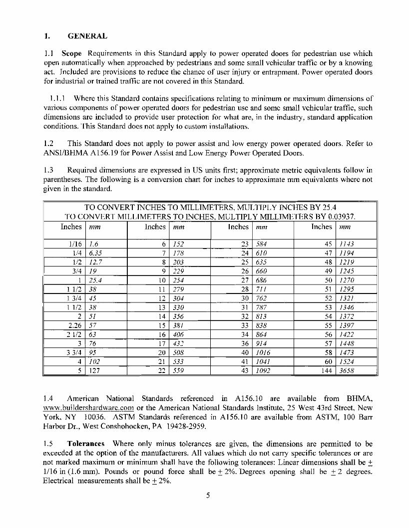
1.3 Required dimensions are expressed in US units first; approximate metric equivalents follow inparentheses. The following is a conversion chart for inches to approximate mm equivalents where notgiven in the standard.
TO CONVERT INCHES TO MILLIMETERS, MULTTPLY INCHES BY 25.4TO CONVERT MILLIMETERS TO INCHES, MULTIPLY MILLIMETERS BY 0.03937.
Inches mm Inches mm Inches mm Tnches mm
1/16 1.6 6 152 23 584 45 11431/4 6.35 7 178 24 610 47 11941/2 12.7 8 203 25 635 48 12193/4 19 9 229 26 660 49 1245
I 25.4 10 254 27 686 50 1270I 1/2 38 II 279 28 7/1 51 1295I 3/4 45 12 304 30 762 52 1321I 1/2 38 13 330 31 787 53 1346
2 51 14 356 32 813 54 13722.26 57 15 381 33 838 55 139721/2 63 16 406 34 864 56 1422
3 76 17 432 36 914 57 14483 3/4 95 20 508 40 1016 58 1473
4 102 21 533 41 1041 60 15245 127 ..,,, 559 43 1092 144 3658
1.4 American National Standards referenced in A156.10 are available from BHMA,www.buildershardware.com or the American National Standards Institute, 25 West 43rd Street, NewYork, NY 10036. ASTM Standards referenced in A156.10 are available from ASTM, 100 BarrHarbor Dr., West Conshohocken, PA 19428-2959.
1.5 Tolerances Where only minus tolerances are given, the dimensions are permitted to beexceeded at the option of the manufacturers. All values which do not carry specific tolerances or arenot marked maximum or minimum shall have the following tolerances: Linear dimensions shall be ±1/16 in (1.6 mm). Pounds or pound force shall be ±2%. Degrees opening shall be ±2 degrees.Electrical measurements shall be ±2%.
5
1.6 Tests described in this standard are performed under laboratory conditions. Measurements shallbe taken under neutral air pressure conditions. In actual usage, results vary because of installation.maintenance and environmental conditions.
1.7 Doors used as fire doors or smoke barriers have additional requirements not covered in thisstandard.
1.8 Where required by the authority having jurisdiction, products meeting the requirements of thisStandard are required to comply with UL 325-Fifth Edition June 2002, and be listed or labeled by anationally recognized independent testing laboratory and be under a periodic examination service.
1.9 Tests described in paragraphs 7.6 and 12 shall be performed under the supervision of a nationallyrecognized independent testing laboratory on preproduction samples prior to acceptance of the designfor production and subsequent installation. Production units shall be lUlder an in-plant follow-upinspection service.
2. DEFINITIONS OF TERMS USED IN TillS STANDARD
2.1 Active Area The area where a sensor or control mat detects presence or motion.2.2 Activating Zone An area created by a sensor or control mat such that the door will open whenthe area is entered by (a) person(s) .2.3 Activating Zone, Secondary An area created by a sensor or control mat such that the door willreactivate or reverse and remain active until the door is almost closed.2.4 Automatic Door Operator A power operated mechanism that is attached to a door for thepurpose of mechanically opening and closing a door upon the receipt of an activating signal.2.5 Back Check The checking or slowing down of the speed of door opening before being fullyopened. (Also called Open Check.)2.6 Balanced Door A door equipped with a hinge which moves the hinge pivot point from the hingestile of the door towards the centerline of the door.2.7 Break Away Device A safety device other than an exit device that permits egress underemergency conditions. (Also called Emergency Release.)2.8 Break Out The process of activating a break away device causing the door or panel to swing inthe direction of egress.2.9 Center Pivoted A door which has the pivot point of the hinge located on the centerline of thedoor thickness.2.10 Clear Opening for Automatic DoorsNote: The following is for the purpose of sizing activating and safety zones. Refer to applicablebuilding codes for means of egress clear width requirements.
Swing Doors With the door open 90 degrees, the clear opening is measured between the face ofthe door and jamb or jamb stop.
Pair of Swing doors With the doors open 90 degrees the clear opening is measured between thefaces ofthe two open doors.
Sliding or Folding Doors In the fully opened position, the clear opening is measured from theedge of the leading stile to the jamb or jamb stop ifpresent.
Pair of Sliding or Folding Doors In the fully opened position, the clear opening is measuredbetween the edges of the leading stiles of the two doors.2.11 Closing Cycle Movement of a swinging, folding or sliding door from the fully open position tothe fully closed position.2.12 Closing Time Time from starting of a door closing until it is at rest fully closed.
6

2.13 Control A unit containing electrical components for automatic control of door operation andoverload protection.2.14 Control Mat An activating or safety device placed on the floor on either side of a doorwaysensing the presence of a person. It is constructed of a rubber like material with slip resistant surfaceand is either recessed into or surface mounted on the floor.2.15 Control Mat, Activating A control mat which when activated causes a door to open.2.16 Control Mat, Safety A control mat which when activated prevents a door from opening orholds a door open.2.17 Custom Installations Where an installation condition exists such that all of the performancecriteria of this standard carmot be met.2.18 Cycle The action of an automatic door operator starting with activating through opening and fullclosing of (a) door(s).2.19 Door Opening for Automatic DoorsNote: The following is for the purpose of sizing activating and safety zones. Refer to applicablebuilding codes for means ofegress clear width requirements.
Swing or Folding Doors (Singles or Pairs) The smallest width dimension of a door opening,measured jamb to jamb.
Sliding Doors Same as clear opening.2.20 Double Egress Power Operated Swing Doors A pair of doors that simultaneously swing withthe two doors moving in opposite directions with no mullion.2.21 Face of Door The plane of the highest part of the door exposed to view when the door is closed.Does not include hardware or other applied products.2.22 Exposed Area The visible area of a control mat after the trim is installed.2.23 Finger Guard A device applied at the hinge stile of a door or to the hinge jamb adjacent to thedoor preventing damage to hands or fingers.2.24 Folding Door A pivoted swing panel hinged to a passive panel, the other end of which iscaptured in a guide, thus allowing it to slide as both panels swing into a V shape (the fold).2.25 Guide Rail A separator used with power operated doors for traffic separation and control.2.26 Inactive Area The area where a sensor or control mat does not detect presence or motion.2.27 Knowing Act With reference to the act of operating a door operator, such as pressing a switch withthe knowledge ofwhat will happen.2.28 Latch Check The checking or slowing down of the speed of closing a door before being fullyclosed. (Also called Close Check.)2.29 Offset Hung A door which has a hinge pivot point located off the centerline of the doorthickness.2.30 Motion Sensor A sensor designed to detect the movement of a person in the vicinity of thedoorway and give a control signal to the power operated door.2.31 Power Operated Door The combination of door, operator and controls constituting the system.(Also called Automatic Door.)2.32 Presence Sensor A sensor designed to detect the presence of a stationary person in the vicinityof the doorway and give a control signal to the power operated door.2.33 Safety Zone An area of detection provided by presence sensors or control mats on swinging orfolding doors.2.34 Small Vehicular Carts used to transport people or objects.2.35 Threshold A floor mounted horizontal member installed beneath a closed door or in a clear dooropemng.2.36 Trained Traffic People trained in the safe use and operation of a particular automatic doorinstallation.2.37 Trim, Mat Material installed around the perimeter of a control mat securing it to the floor.
7

Section 6Section 7 or 8Section 9Section 10Section II
Section 6Section 7 or 8Section 9Section 10Section 11
3. SWINGING DOORS
3.1 Automatic swing door systems have a variety of configurations, including:• a single door swinging in or out, left-handed or right-handed• a pair of doors simultaneously swinging in the same direction• a pair of doors simultaneously swinging in opposite directions (double egress)
3.2 The door operator is concealed or surface applied. The doors are center pivoted, offset hung,balanced or hinged. No matter what the configuration or system, automatic swinging doors shallinclude guide rails, sensors or control mats, and signage for the safety and convenience of the useraccording to the following:
Guide RailsControl Mats or SensorsKnowing Act (when applicable)EntrapmentSignage
4. SLIDING DOORS
4.1 Automatic sliding doors are flat panels that slide horizontally and linearly. These systems havesuch a variety of configurations that symbols have been assigned to the individual panels that make upan entryway. See Table I for definitions of 0, SO, X, SX and P panels.
4.2 No matter what the configuration or system, automatic sliding doors shall include sensors orcontrol mats, and signage for the safety and convenience of the user according to the following:
Control Mats or Sensors Section 7 or 8Knowing Act (when applicable) Section 9Entrapment Section 10Signage Section II
S. FOLDING DOORS
5.1 Automatic folding doors are comprised of two or more separate panels, of which one panelswings, and the other panel slides in a guide. Because of the number ofleaves involved, see Figure A14 for definitions of FX and FS panels.
5.2 Automatic folding doors include a variety of configurations, including:• a single folding door folding in or out, left-hand or right-hand• a pair of doors simultaneously folding in or out, left-hand and right-hand
5.3 No matter what the configuration or system, automatic folding doors shall include guide rails,sensors or control mats, and signage for the safety and convenience of the user according to thefollowing:
Guide RailsControl Mats or SensorsKnowing Act (when applicable)EntrapmentSignage
6. GUIDE RAILS
8
6.1 Guide Rails for Swing Doors (See Figures A-I, A-2, A-3, A-4, A-II, A-12A,B,C, A-19A,B,C)
6.1.1 Two guide rails shall be installed on the swing side of each door. Single doors shall have oneon each side of the door and pairs or double egress shall have one rail on each hinge side. Rails shallproject at least to the leading edge of the widest door in the fully open position.Exception #1: A wall or separator is permitted to be used in place of a rail, provided that it meets thecriteria in 6.1.2 through 6.1.5Exception #2: Guide rails for swinging doors serving both egress and ingress shall project out fromthe face of the door jambs on the swing side to no less than the outside leading edge of the open doorplus 55 in. (See Figures A-2, A-4 &A-12A.C.)Exception #3 If double egress doors or a pair of doors are installed in a hallway, no guide rails arerequired if the distance between the wall and the door in the 90 degree open position does not exceedlOin. (A-19 A,B,C)Exception #4 Guide rails for Knowing Act swinging doors serving both egress and ingress shallproject out from the face of the door jambs on the swing side to no less than the outside leading edgeof the open door plus 12 in.
6.1.2 A guide rail shall be 30 in. high minimum measured from the floor surface.
6.1.3 A guide rail shall have a panel or a divider to inhibit access to the protected area.
6.1.4 There shall be 6 in. maximum clearance between the rail and the door in the fully openposition or between the rail and the leading edge of the door at the point in its arc of travel when it isclosest to the rail. There shall be a 2 in. minimum clearance between the rail at the hinge side and thedoor in the fully open position.
6.1.5 Free standing guide rails shall have a maximum dimension between the rail and jamb (orother adjacent surface) of 6 in.
6.2 Guide Rails for Folding Doors (See Figures A-14, A-15, A-16, A-17-A,B,C,D)
6.2.1 Two guide rails shall be installed on the fold side of the door. Single doors shall have one oneach side of the door; pairs shall have one rail on each hinge side and shall project beyond the foldopen position not less than:
12 in. for two way traffic or one way traffic approaching the fold side or5 in. for one way traffic approaching the non fold side.
Exception: A wall separator is permitted to be used in place of a rail, provided that it meets thecriteria in 6.2.2 through 6.2.5
6.2.2 A guide rail shall be 30 in. high minimum measured from the finished floor surface.
6.2.3 A guide rail shall have a panel or divider to inhibit access to the protected area.
6.2.4 There shall be 6 in. maximum clearance between the rail and the door in the fully openposition or between the rail and the leading edge of the door at the point in its arc of travel when it isclosest to the rail. There shall be a minimum clearance of 2 in. between the rail at the hinge side andthe door in the fully open position.
6.2.5 Free standing guide rails shall have a maximum clearance between the rail and jamb (or otheradjacent surface) of 6 in.
7. CONTROLMATSREQumEMENTS
7.1 General Requirements for Mats
9

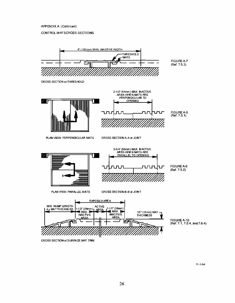
7.1.1 The edge of the exposed area of all control mats shall not exceed 1/2 in. thickness. (See FigureA-I0.)
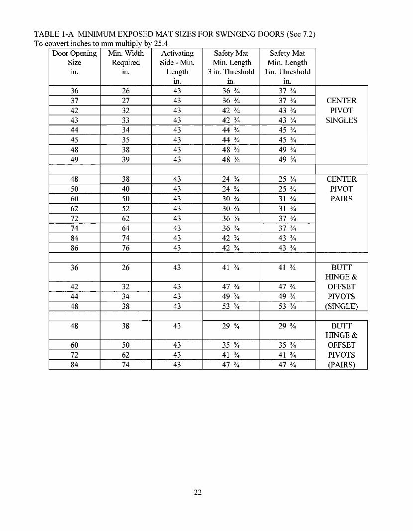
7.2 Swinging Doors (See Table I-A)
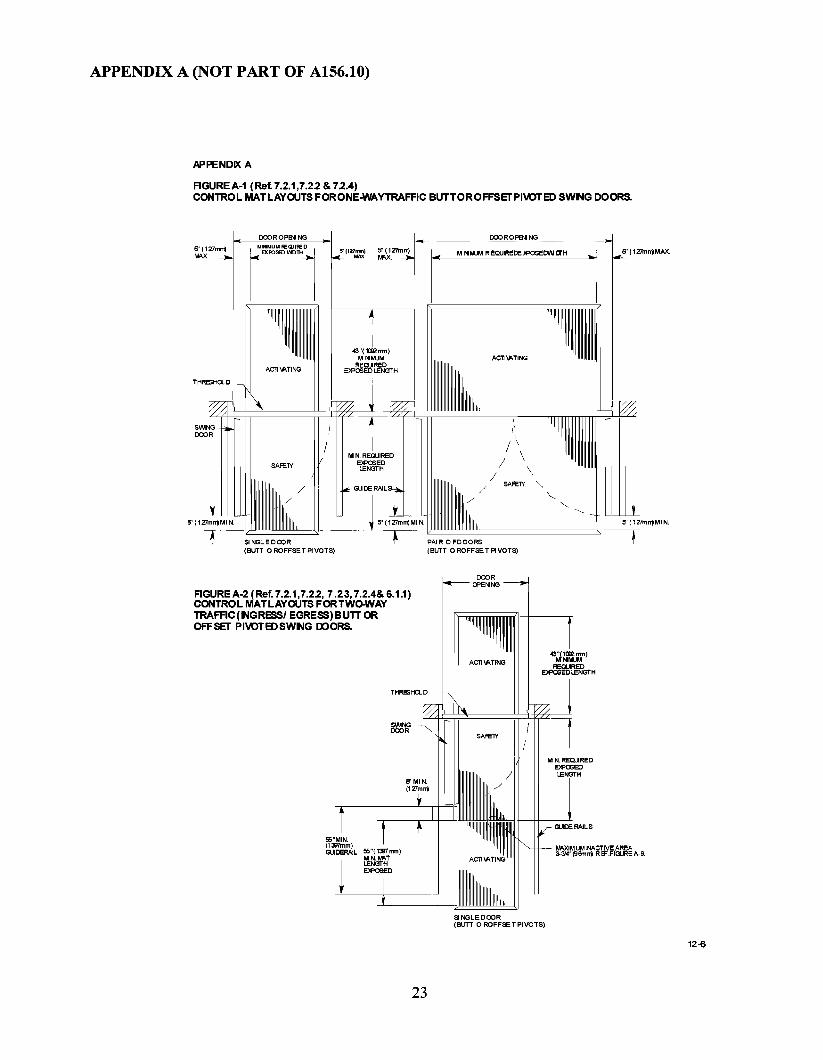
7.2.1 The width of the exposed area of an activating or safety control mat shall be the width of thedoor opening less a maximum of 5 in. measured from both sides for a total maximum of lOin. (SeeFigures A-I, A-2, A-3, A-4, A-12A.)
7.2.2 A safety zone shalJ be provided by a safety control mat on the swing side of the door. Thelength of the exposed area shall extend a minimum of 5 in. beyond the lead edge of the door in the openposition. (See Figures A-I, A-2, A-3, A-4, A-12A.)
7.2.3 Swinging doors serving both egress and ingress, including non-knowing act double egressdoors, shall have a series of control mats on the swing side of the door(s) consisting of a safety controlmat nearest the opening with a length of exposed area a minimum of 5 in. beyond the lead edge of thedoor in the open position and one or more activating control mats totaling an additional 55 in. ofexposed length. (See Figure A-2 & A-4.)
7.2.4 The exposed length of the activating mat on the non swing side shall be a minimum of 43 in.(See Figures A-I, A-2, A-3, A-4.)
7.3 Sliding Doors
7.3.1 The width of the exposed area of an activating mat shall be the clear opening width less amaximum of 5 in. measured from both sides for a total maximum of lOin. (See Figures A-5 & A-6.)
7.3.2 Sliding doors shall have an activating control mat with a minimum exposed length of 43 in.(See Figures A-5 & A-6.)
7.3.3 Sliding doors used for one way traffic shall be provided with a control mat that will hold thedoor open or return the door to the open position when approached by a person from the side notintended for approach. The activating length shall extend a minimum of 24 in. from the face of thedoor. The width of the control mat shall comply with 7.3.1. The control mat shall be deactivated whenthe door(s) is (are) within 6 in. of the fully closed position.
7.4 Folding Doors
7.4.1 The width of the exposed area of an activating or safety control mat shall be the width of thedoor opening less a maximum of 5 in. measuring from both sides for a total maximum of 10 in. (SeeFigure A-16.)
7.4.2 A safety zone shall be provided by a safety control mat on the fold side of the door. Thelength of the exposed area shall extend a minimum of 5 in. beyond the edge of the door in the openposition. (See Figure A-16.)
7.4.3 Folding doors serving both egress and ingress shall have a series of control mats on the foldside of the door(s) consisting of a safety control mat nearest the opening with a minimum of 5 in.beyond the edge of the FS panel in the open position, and one or more activating control mats totalingan additional 43 in. of exposed length. (See Figure A-16.)
7.4.4 The exposed length ofthe activating mat on the non fold side shall be a minimum of43 in.
7.5 Joining of Control Mats
7.5.1 Control mats are permitted to be fitted side by side with the longest dimension perpendicularto the opening and shall not have an inactive area at the meeting line exceeding 2-1/2 in. (See FigureA-S.)
10

7.5.2 Control mats are permitted to be fitted side by side with the longest dimension parallel to thedoor opening and shall not have an inactive area at the meeting line exceeding 3-3/4 in. (See Figure A9.)
7.5.3 Control mats meeting at a threshold shall not have an inactive area exceeding 6 in. includingthreshold width. (See Figure A-7.)
7.5.4 The active area of a control mat shall be a maximum of 1-1/2 in. from any edge of theexposed area. (See Figure A-10.)
7.6 Performance Requirements ofControJ Mats
7.6.1 A control mat circuit shall operate at 30 volts rms or less.
7.6.2 Control Mat Sensitivity Test
7.6.2.1 Circuit shall be activated when a solid steel test disc 2.26 in. in diameter is depressedwith a 25 Ibf (110 N) applied vertically, perpendicular to the disc in accordance with 7.6.2.3 and7.6.2.4, except that if the circuit is not activated, a 30 Ibf (130 N) shall be applied at the area of theelectrical contact connections and adjacent locations described in 7.6.2.3. Activation is achieved whenthe "off' state circuit resistance and capacitance, which must be greater than 5000 ohms and less than100 nanofarads, changes to an "on" state circuit resistance of less than 400 ohms.
7.6.2.2 The Control Mat shall be divided into 12 equal rectangles covering the active area,except when the length of the mat is such that the length of each rectangle would be greater than 12 in.then the mat shall be divided into 15 or 18 equal rectangles so that the length of each rectangle is notless than 8 in. nor more than 12 in.
7.6.2.3 The test disc shall be placed in the approximate center of each interior rectangle. Forperimeter rectangles, place the disc so that it abuts the edge of the active area 1-1/2 in. from theexposed edge of the mat at the approximate center line of the rectangle. Compensating for the weightof the disc, apply a force to activate the circuit and take a single reading. If the disc and force fail toactivate the Control Mat at any of the test locations, place the disc on adjacent 90 degree tangents tothe test location(s) within the active area of the mat. The disc shall activate the mat at all adjacentlocations. If a check on the initial reading is desired, a period of at least 10 minutes shall be allowedbetween readings. One test disc diameter shall be omitted from each comer of the mat when testing.The mats shall be tested on a flat, rigid surface.
7.6.2.4 The test shall be conducted at 68 degrees ± 5 degrees F (20 degrees ± 2 degrees C).Mats shall be placed in the test room not less than four hours prior to the test.
7.6.3 Control Mat Friction Test
7.6.3.1 A control mat shall have a coefficient of friction when dry and clean of not less than0.66 when tested in accordance with 7.6.3.
7.6.3.2 Coefficient of friction (M) shall be measured using a standard friction block (N)having a diameter of 4 inches (100 rom), weighing 15 lbs. (7 kg) and equipped with a Neolite bottom1/4 in. thick. The Neolite composition rubber shall have a smooth flat bottom surface without ridgesand Shore A hardness of90 ±3. The sheen shall be removed from the Neolite surface prior to use. Toprepare the assembly surface prior to its initial use, place a sheet of 400 grit wet or dry silicon carbidepaper on a flat surface. Sand the Neolite material gently by moving the assembly back and forth fourtimes for a distance of about 4 in. Repeat at an angle of 90 degrees. This constitutes one cycle ofsurface preparation. This procedure is to be repeated for a total of 10 cycles.
7.6.3.3 The block shall be placed in the middle of the mat with a linear scale calibrated in
11


door to reverse direction, stop or slow down to a maximum latch edge speed of 4 in. per secondmeasured within I in. ofthe latch edge before any contact is made. (See Figme A-12B&C.)
8.2.3 Swinging doors serving both egress and ingress, including non-knowing act double egressdoors, shall have on the swing side, a safety zone as defined in 8.2.2 and an activating zone. The lengthof the activating zone shall be established as follows: the activating zone starts adjacent to the safetyzone and extending an additional 55 in. from the leading edge of the door in the open position. (SeeFigme A-12A&C.) The activating zone shall have a minimum width equal to the width of the clearopening measured at 8 in. and 30 in. from the interface of the safety and activating zones.
8.2.4 If a sensor is used for activating and a safety control mat is used as a safety zone, the exposedarea of the safety control mat shall extend 5 in. minimum beyond the edge of the door in the openposition and:(1) extend 5 in. into the non swing side area ofthe door measured from the face of the door; or(2) the door opening area shall be provided with a presence sensor \vhich shall be used to prevent afully open door(s) from closing when a person is in the space between two non overlapping activatingor safety zones; or(3) the door closing cycle shall have a delay of four seconds minimum after the activating zone isclear; or(4) be equipped with a door mounted sensor on the non swing side as described in 8.2.2.2.
8.2.4.1 The width of a safety control mat shall be in accordance with 7.2.1. (See Figure A-12A.)
8.2.5 When sensors are used to provide both an activating and a safety zone, if the distancebetween the two non overlapping zones exceeds 8 in. the door system shall:(1) be equipped with a safety control mat; or(2) be equipped with a presence sensor across the door opening; or(3) have a door closing cycle delay of 4 seconds minimum after the activating zone is clear; or(4) be equipped with a door mounted sensor on the non swing side as described in 8.2.2.3.
8.3 Sliding Doors
8.3.1 Sliding doors shall have an activating zone as defined in 8.1.1.
8.3.2 A presence sensor shall be used to detect a person in the space between two non overlappingactivating zones for the width of the clear opening as follows:
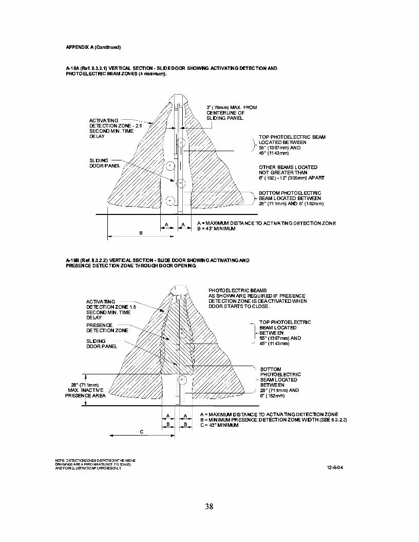
8.3.2.1 Ifphoto electric beams are used (See Figure A-18A):(1) a minimum of fom photo electric beams shall be installed, two minimum on each side of thesliding door. The beams' location shall alternate from side to side. The lowest beam shall be installed6 to 28 in. from the floor and the other three at a spacing between 6 and 12 in. apart with the top beamat 45-55in. from the floor. The photo electric beam area of detection shall extend across the clear dooropening. (See Figure A-18A); and(2) the beams shall be installed within 3 in. from the centerline of the slide door; and(3) the beams shall remain active from fully open to within 6 in. of closed; and(4) the door shall remain fully open for 2.5 seconds minimum after loss of detection.
8.3.2.2 If an overhead presence sensor is used through the door opening it (See figure A-18B.):(1) shall detect a 28 in. minimum high person and extend out a minimum of 5 in. from the face of thedoor on each side; and
13

(2) the detection zone shall remain active from open to within 6 in. of closed or shall have a minimumof two photo electric beams on one side of the door, with the lower beam installed 6-28 in. and topbeam 45-55 in. from the floor. (See Figure A-18B.);(3) if beams are required they shall be installed within 3 in. from the centerline of the slide door andremain active from fully open to within 6 in. of closed; and(4) the door shall remain fully open for 1.5 seconds minimum after loss of detection.
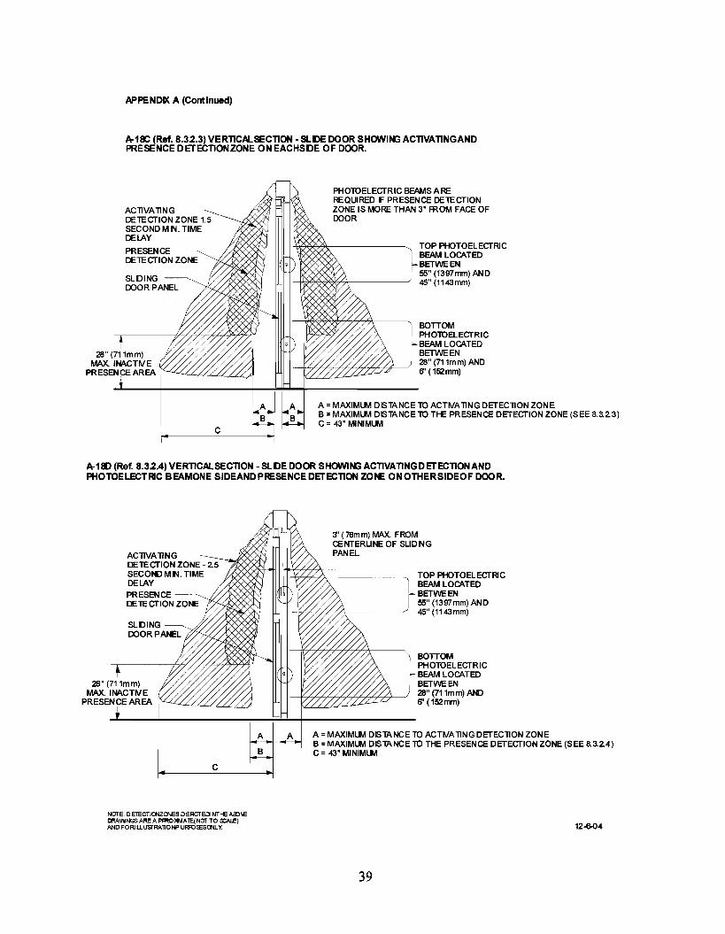
8.3.2.3 If overhead presence sensors are installed on each side of the sliding door opening (SeeFigure A-18C.):(I) they shall not have an inactive area more than 5 in. extending out from the face of the door. If theinactive area exceeds 3 in. from the face of the door, it shall have a minimum of two photo electricbeams on one side of the door, with the lower beam installed 6-28 in., and top beam 45-55 in. from thefloor; and(2) the detection zone shall remain active from open to within 6 in. of closed;(3) if beams are required they shall be installed within 3 in. from the centerline of the slide door andremain active from fully open to within 6 in. of closed; and(4) the door shall remain fully open for 1.5 seconds minimum after loss of detection.
8.3.2.4 If photo electric beams are used on one side of the door and an overhead presence sensoris installed on the opposite side of the sliding door opening (See Figure A-18D):
(1) a minimum of two photo electric beams shall be installed on one side ofthe door with the lowerbeam installed 6-28 in. and top beam 45-55 in. from the floor; and
(2) the beams shall be installed within 3 in. from the centerline of the slide door; and(3) the overhead presence sensor installed on the side opposite the beams shall not have an inactive
area more than 5 in. extending out from the face ofthe door; and(4) the beams and overhead presence sensor must remain active from fully open to within 6 in. of
closed; and(5) the door shall remain fully open for 2.5 seconds minimum after loss of detection.
8.3.3 Sliding doors used for one way traffic shall be provided with a secondary activating zone onthe side not intended for approach. The secondary activating zone shall extend a minimum of 24 in.from the face of the door and be effective to within 5 in. from the face of the door measured at thecenter of the door opening. The zone shall have a minimum width equal to the width of the clearopening measured at 8 inches perpendicular from the face of the closed door. The sensor shall bedeactivated when the door(s) is (are) within 6 in. of the fully closed position.
8.4 Folding Doors
8.4.1 Folding doors shall have an activating zone as defined in 8.1.1.
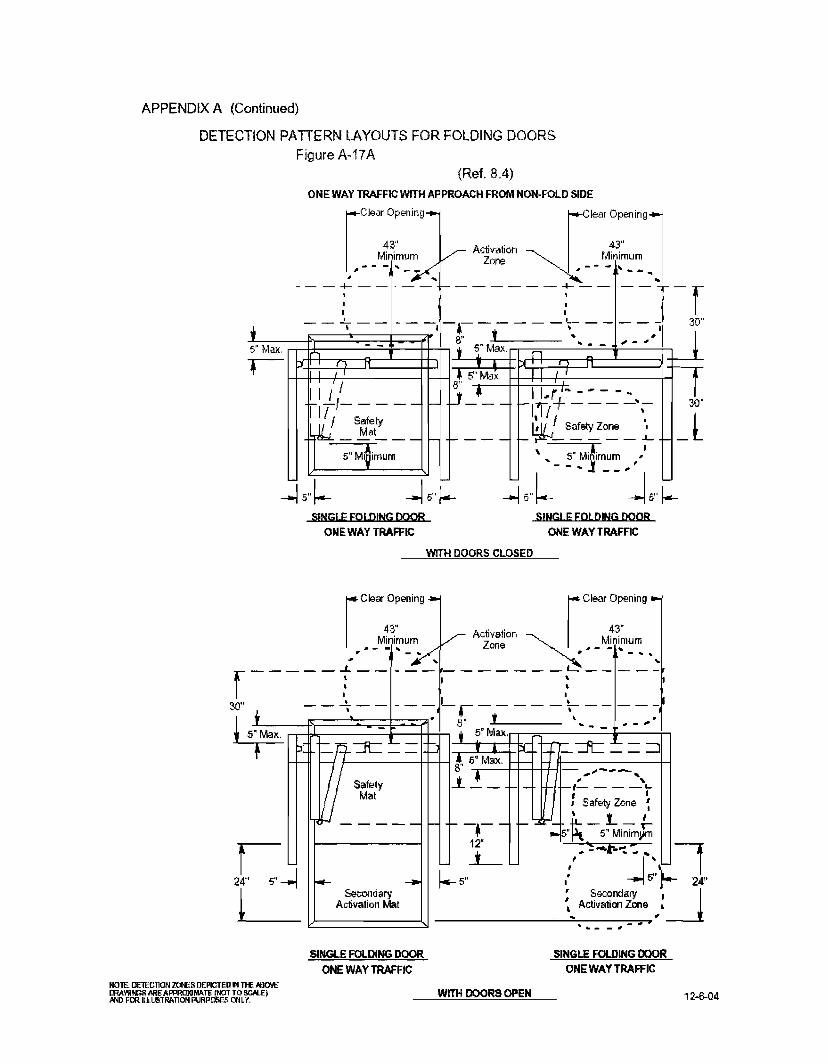
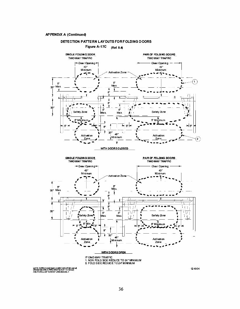
8.4.2 A safety zone shall be provided on the fold side of all power operated folding doors that shallextend 5 in. minimum beyond the edge of the FS panel measured when open. Detection shall beeffective to within 5 in. from the face of the door. The width of the safety zone when the door isclosed shall be equal to the door opening less 5 in. maximum from both sides for a total of lOin.maximum. The width of the safety zone when the door is open shall be equal to the clear opening less5 in. maximum from both sides for a total of lOin. maximum measured 8 in. perpendicular to the door.When the safety zone is occupied by a 28 in. minimum high person fully in the safety zone of a fullyopen or closed door, the door operator shall not operate. (See figure A-17A, 17B, 17C & 17D.)
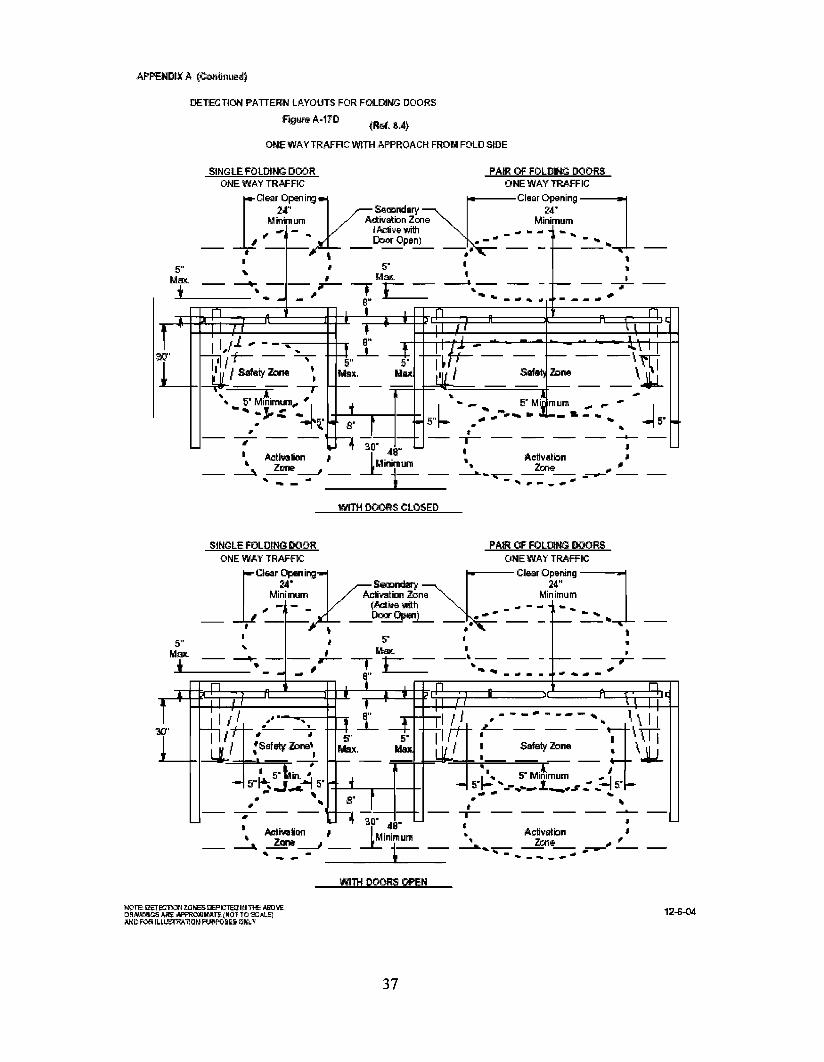
8.4.2.1 One way traffic doors with an intended approach from the fold side of the door shallhave a secondary activating zone that extends a minimum of 24 in. on the non-fold side from the face
14

of the closed door and be effective within 5 in. from the face of the door measured at the center of theclear opening. The zone shall be deactivated when the door(s) is (are) within 6 in. or less of the fullyclosed position. (See Figure A-17D.)
8.4.2.2 One way traffic doors with an intended approach from the fold side shall have anactivating zone on the fold side with a minimum width equal to the clear opening measured at 8 in. and30 in. from the outer edge of the safety zone and perpendicular to the face of the closed door. (SeeFigure A-l70.)
8.4.2.3 Folding doors for one way traffic with intended approach from the non-fold side shallhave. on the folding side of the door, both a safety zone as defined in 8.4.2 and a secondary activatingzone. The length of the secondary activating zone on the fold side shall be established as follows: Thezone starts adjacent to the safety zone and shall extend 24 in. beyond the edge of the FS panel whenopen. (See Figure A-17A&B.) The zone shall have a minimum width equal to the width of the clearopening measured at 8 in. from the outer edge of the safety zone and perpendicular to the face of theclosed door. The sensor shall be deactivated when the door(s) is (are) within 6 in. of the fully closedposition.
8.4.3 Folding doors serving both egress and ingress shall have, on the folding side of the door, botha safety zone as defined in 8.4.2 and an activating zone. The length of the activating zone shall beestablished as follows: The activating zone (as defined in 8.4.1) starts adjacent to the safety zone andshall be effective to within 5 in. and shall extend 48 in. beyond the edge of the FS panel when open.(see Figure A-17C). The activating zone shall have a minimum width equal to the width of the clearopening measured at 8 in. and 30 in. from the outer edge of the safety zone and perpendicular to theface of the closed door.
8.4.4 When both activating and safety control mats are used in combination with sensors they shallbe in accordance with section 7.4. (See Figure A-17A & A-17B.)
8.4.5 If a sensor is used for activating and a safety control mat is used as a safety zone. the exposedarea of the safety control mat shall extend 5 in. minimum beyond the edge of the FS panel in the openposition and:(I) extend 5 in. into the approach area of the door measured from the face of the door in the closedposition;(2) the door opening area shall be provided with a presence sensor which shall be used to prevent afully open door(s) from closing when a person is in the space between two non overlappingactivating/safety zone; or(3) the door closing cycle shall have a delay of four seconds minimum after the activating zone isclear. (See Figure A-17A & A-17B.)
8.4.6 When sensors are used to provide both an activating and safety zones, if the distance betweenthe two non overlapping zones exceeds 8 in. the door system shall:(I) be equipped with a safety control mat;(2) the door opening shall be equipped with a presence sensor across the door opening; or(3) have a door closing cycle delay of four seconds minimum after the activating zone is clear. (SeeFigure A-17A & A-17B.)
9. KNOWING ACT DOOR ACTIVATION
9.1 Swinging, Sliding, and Folding Doors Use of an activating device which requires a knowing actto activate the automatic door shall meet the following requirements:
9.1.1 Be installed in a location within view of the automatic door; and
15

9.1.2 Have an installation height of a minimum of36 in. and a maximum of 48 in.; and9.1.3 Be located a maximum distance of 12 feet (3.7 m) from the center of the door, and remain
accessible from the swing or fold side when the door is opened and shall not be located in a positionwhere the user would be in the path of the moving door; and
9.1.4 The door shall remain fully open for a minimum of five seconds after release of the knowingact device; and
9.1.5 The door shall be equipped with a safety zones, time delays, and guide rails as required inthis standard for the type door and detection system selected.
9.1.5.1 Swinging (except double egress), sliding, and folding doors shall be equipped with asecondary activating zone as follows:(I) Sliding doors required for one or two way traftic requires a secondary activating zone on each sidethe door.(2) Swinging and folding doors for one or two way tratTtc only require the secondary activating zoneon the non-swing or non-fold side of the door.(3) The secondary activating zone (s) shall extend a minimum of24 in. from the face of the door andbe effective to within 5 in. from the face of the door measured at the center of the door opening. Thesecondary activating zone shall have a minimum width equal to the clear door opening. The secondaryactivating device for sliding and folding doors shall be deactivated when the door (s) is (are) within 6in. of the fully closed position. The secondary activating zone for swinging doors must remain activewhile the door is closing and shall be deactivated within the last 10 degrees of closing.
9.2 Double Egress Automatic Swing Doors The activating device shall meet the requirements of9.1.1 through 9.1.4.
9.2.1 One of the following safety zones is required:a. If an overhead sensor(s) is used to provide a safety zoue, the length of the active area shall be
effective to within 5 in. of the face of the closed door measured at the center of the dooropening. The safety zone shall extend 5 in. minimum beyond the leading edge ofthe door inthe open position when measured at the center of the door opening. Overhead mounted sensorsshall provide a detection zone equal to the door panel width minus 5 in. from the pivot jamband to within 5 in. of the lead edge ofthe door, measured at 8 and 30 in. parallel to the doorface (A-19A).
b. Door mounted sensors shall meet 8.2.2.3. (A-19B)c. Mats The safety zone shall extend 5 in. minimum beyond the leading edge ofthe door in the
open position when measured at the center of the door opening. Mats shall provide a detectionzone equal to the door panel width minus 5 in. from the pivot jamb, and to within 5 in. of thelead edge of the door. (A-19C)
9.2.2 The door shall be equipped with a secondary activating zone on the approach side ofthe swingdoor as it swings away from the user. (A-19A, A-19C)
a. The secondary activating zone for sensors shall come to within 5 in. of the face of the doormeasured at the center of the door opening. If control mats are llsed they must extend aminimum 24 in. from the face of the door.
b. The width of the secondary activating zone shall be equal to the width of the door panel less 5in. from each side in the closed position.
c. The secondary activating zone must remain active while the door is closing and shall bedeactivated within the last 10 degrees of closing.
16
9.2.3 The doors shall be simultaneously operated.
9.3 Swinging and folding door safe!)' zones shall be active when the door (s) are closed and shallhave the same zone sizes as required for non Knowing Act activation.
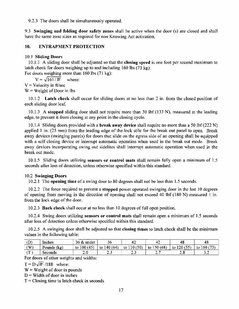
10. ENTRAPMENT PROTECTION
10. I Sliding Doors10.1.1 A sliding door shall be adjusted so that the closing speed is one foot per second maximum to
latch check for doors weighing up to and including 160 lbs (71 kg):For doors weighing more than 160 lbs (71 kg):
V = .J161/ W where:V = Velocity in ft/secW = Weight of Door in lbs
10.1.2 Latch check shall occur for sliding doors at no less than 2 in. from the closed position ofeach sliding door leaf.
10.1.3 A stopped sliding door shall not require more than 30 Ibf (133 N), measured at the leadingedge, to prevent it from closing at any point in the closing cycle.
10.1.4 Sliding doors provided with a break away device shall require no more than a 50 Ibf (222 N)applied 1 in. (25 mm) lrom the leading edge of the lock stile for the break out panel to open. Breakaway devices (swinging panels) for doors that slide on the egress side of an opening shall be equippedwith a self closing device or interrupt automatic operation when used in the break out mode. Breakaway devices incorporating swing out sidelites shall interrupt automatic operation when used in thebreak out mode.
10.1.5 Sliding doors utilizing sensors or control mats shall remain fully open a minimum of 1.5seconds after loss of detection, unless otherwise specified within this standard.
10.2 Swinging Doors10.2.1 The opening time of a swing door to 80 degrees shall not be less than 1.5 seconds.
10.2.2 The force required to prevent a stopped power operated swinging door in the last 10 degreesof opening from moving in the direction of opening shall not exceed 40 lbf (180 N) measured 1 m.from the lock edge of the door.
10.2.3 Back check shall occur at no less than 10 degrees of full open position.
10.2.4 Swing doors utilizing sensors or control mats shall remain open a minimum of 1.5 secondsafter loss of detection unless otherwise specified within this standard.
10.2.5 A swinging door shall be adjusted so that closing times to latch check shall be the minimumvalues in the following table:
(0) Inches 36 & Ill1der 36 42 42 48 48(W) POlll1ds (kg) to 100 (45) to 140 (64) to 110 (50) to 150(68) to 120 (55) to 160(73)(T) Seconds 2.0 2.3 2.3 2.7 2.8 3.2
For doors of other weights and Widths:
T = D.JW /188 where:W = Weight of door in poundsD = Width of door in inchesT = Closing time to latch check in seconds
17
10.2.6 Latch check shall occur for swinging door at no less than 10 degrees from closed positionand the door shall not close through the final 10 degrees in less than 1.5 scconds.
10.2.7 The force required to prevent a stopped power operated swinging door from moving in thedirection of closing shall not exceed a 30 Ibf (133 N) measured 1 in. from the lock edge of the door atany point in the closing cycle.
10.2.8 In the event of power failure, a swing door shall be capable of being opened manually withno greater than a 30 Ibf(l33 N), applied 1 in. from the edge of the lock stile to open.
10.2.9 Swinging doors provided with a hreak away device shall require no more than 50 Ibf (222N) applied I in. from the edge of the lockstile to open. When the door(s) is opened in the break outmode, powered operating components excluding spring power shall not operate the doors.
10.2.10 The opening at hinge side of swinging doors shall be: a) Less than I;' in. wide with thedoor in any position, or b) At least ';' in. wide with the door in any position. A door that does notcomply with the above is acceptable if provided with a finger guard.
10.3 Folding Doors10.3.1 Opening time of a folding door to back check shall not be less than 1.5 seconds.
10.3.2 The force required to prevent a stopped power operated folding door in the last 10 degreesof the opening, from moving in the direction of opening shall not exceed 40 Ibf(l80 N) measured 1 in.from the leading edge ofthe FS leaf.
10.3.3 Folding doors utilizing sensors or control mats shall remain fully open a minimum of 1.5seconds after loss of detection unless otherwise specified within this standard.
10.3.4 A folding door shall be adjusted so that the closing speed to latch check is a maximum of 1foot/sec. (287 nun/sec.) measured at the leading edge.
10.3.5 Latch check shall occur for folding doors at no less than 2 in. from the closed positionmeasured per FX leaf.
10.3.6 A folding door shall not close through the last 2 in. in less than 1.5 seconds for each FX leaf.
10.3.7 A stopped folding door shall not require more than 30 Ibf (133 N). measured at the leadingedge of the FX panel, to prevent it from closing from fully opened to latch check.
10.3.8 Folding doors provided with a break away device shall require no more than 50 Ibf (222 N)applied 1 in. (25 mm) from the edge of the lockstile to open. When the door (s) is opened in the breakout mode, powered operating components excluding spring power shall not operate the doors.
10.3.9 The opening at hinge side of a center pivoted folding door shall be: a) Less than V. in. widewith the door in any position, or b) At least % in. wide with the door in any position. A door that doesnot comply with the above is acceptable ifprovided with a finger guard.
11. SIGNAGE Consistent with section 2.2.1 of ANSI Z535.4, the "signage and warnings"guidelines of A 156.1 0 are recognized, industry-specific standards that predate the adoption of Z535.4and are not replaced by the standards set forth therein.
18
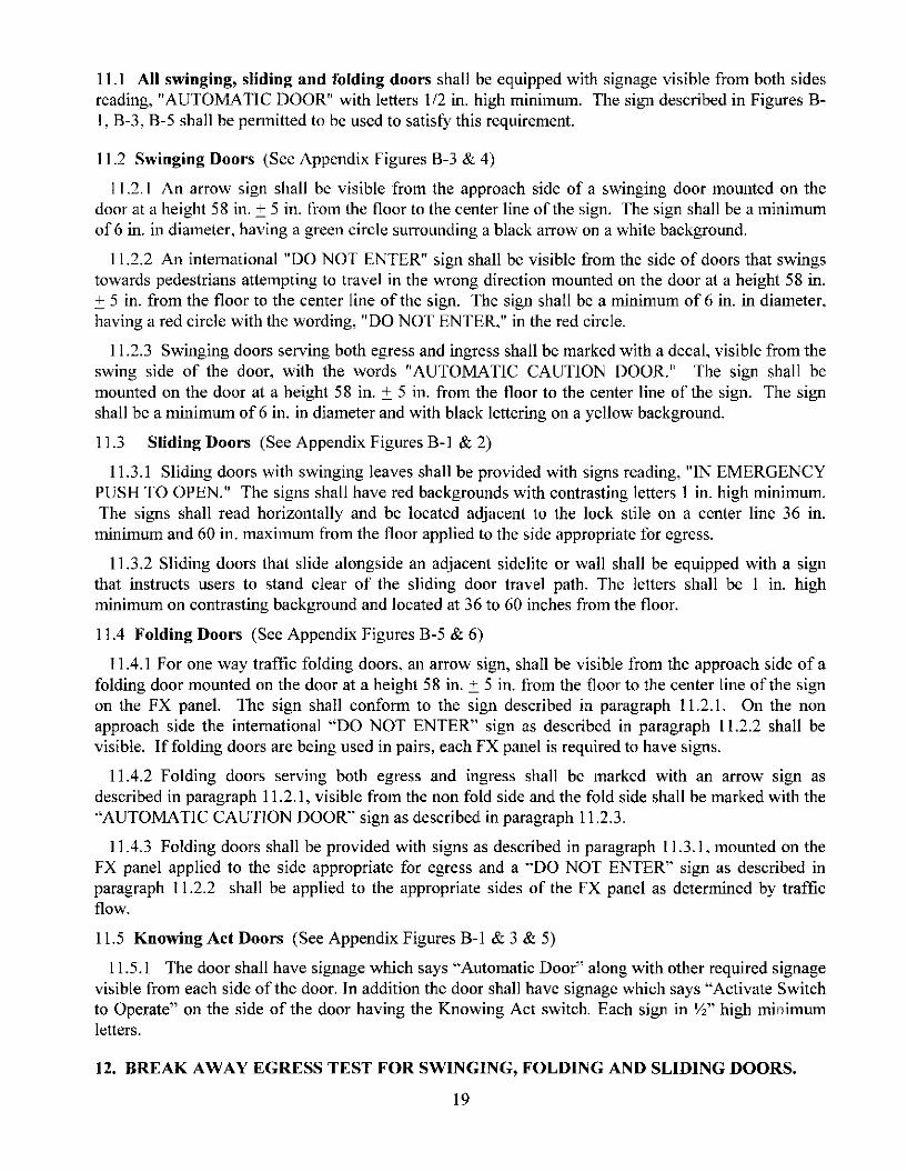
11.1 All swinging, sliding and folding doors shall be equipped with signage visible from both sidesreading, "AUTOMATIC DOOR" with letters 1/2 in. high minimum. The sign described in Figures BI, B-3, B-5 shall be pennitted to be used to satisfY this requirement.
11.2 Swinging Doors (See Appendix Figures B-3 & 4)
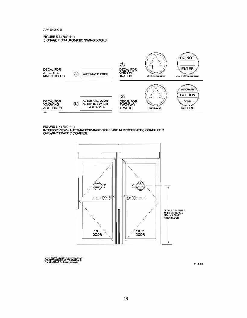
11.2.1 An arrow sign shall be visible from the approach side of a swinging door mounted on thedoor at a height 58 in. ± 5 in. li'om the floor to the center line of the sign. The sign shall be a minimumof 6 in. in diameter, having a green circle surrounding a black arrow on a white background.
11.2.2 An international "DO NOT ENTER" sign shall be visible from the side of doors that swingstowards pedestrians attempting to travel in the wrong direction mounted on the door at a height 58 in.± 5 in. from the floor to the center line of the sign. The sign shall be a minimum of 6 in. in diameter,having a red circle with the wording, "DO NOT ENTER," in the red circle.
11.2.3 Swinging doors serving both egress and ingress shall be marked with a decal, visible from theswing side of the door, with the words "AUTOMATIC CAUTION DOOR." The sign shall bemounted on the door at a height 58 in. ± 5 in. ITom the floor to the center line of the sign. The signshall be a minimum of 6 in. in diameter and with black lettering on a yellow background.
11.3 Sliding Doors (See Appendix Figures B-1 & 2)
11.3.1 Sliding doors with swinging leaves shall be provided with signs reading, "IN EMERGENCYPUSH TO OPEN." The signs shall have red backgrounds with contrasting letters 1 in. high minimum.The signs shall read horizontally and be located adjacent to the lock stile on a center line 36 in.minimum and 60 in. maximum from the floor applied to the side appropriate for egress.
11.3.2 Sliding doors that slide alongside an adjacent sidelite or wall shall be equipped with a signthat instructs users to stand clear of the sliding door travel path. The letters shall be I in. highminimum on contrasting background and located at 36 to 60 inches from the floor.
11.4 Folding Doors (See Appendix Figures B-5 & 6)
11.4.1 For one way traffic folding doors. an arrow sign, shall be visible from the approach side of afolding door mounted on the door at a height 58 in. ± 5 in. from the floor to the center line of the signon the FX paneL The sign shall conform to the sign described in paragraph 11.2.1. On the nonapproach side the international "DO NOT ENTER" sign as described in paragraph 11.2.2 shall bevisible. If folding doors are being used in pairs, each FX panel is required to have signs.
11.4.2 Folding doors serving both egress and ingress shall be marked with an arrow sign asdescribed in paragraph 11.2.1, visible from the non fold side and the fold side shall be marked with the"AUTOMATIC CAUTION DOOR" sign as described in paragraph 11.2.3.
11.4.3 Folding doors shall be provided with signs as described in paragraph 11.3.1, mounted on theFX panel applied to the side appropriate for egress and a "DO NOT ENTER" sign as described inparagraph 11.2.2 shall be applied to the appropriate sides of the FX panel as determined by trafficflow.
11.5 Knowing Act Doors (See Appendix Figures B-1 & 3 & 5)
11.5.1 The door shall have signage which says "Automatic Door" along with other required signagevisible from each side of the door. In addition the door shall have signage which says "Activate Switchto Operate" on the side of the door having the Knowing Act switch. Each sign in Yz" high minimumletters.
12. BREAK AWAY EGRESS TEST FOR SWINGING, FOLDING AND SLIDING DOORS.
19

12.1 Cycle Test Doors with power operators shall be installed in a simulated wall and door framingassembly of sufficient strength to withstand all forces required by the tests. Installation shall be inaccordance with manufacturer's printed instructions. Maintenance and repair of other than break awayequipment is permitted to be performed during the testing cycles.
12.1.1 The test specimen shall be of the largest door size to be listed by the manufacturer.
12.1.2 Cycle for 300,000 cycles at a rate of 5 to 8 per minute.
12.1.3 Break away devices shall not be lubricated or adjusted during the test.
12.1.4 At every 50,000 cycles during the test, the doors shall undergo 1.000 break out cycles. At theconclusion of the test, break out forces shall not exceed those listed in 10.1.4, 10.2.9, and 10.3.8.
12.2 Salt Spray Test
12.2.1 A sample of the latclllng and hinge assembly of the break away device of a power operateddoor contained in an approximately 25 in. wide panel shall be subjected to a salt fog test in accordancewith ANSI/BHMA A156.18-2000 for Materials and Finishes for 168 hours.
12.2.2 Record the release force prior to conducting the test. This shall not exceed 50 1bf (222 N).12.2.3 At the conclusion of the exposure time, remove the sample and allow to dry for 24 hours
without cleaning.12.2.4 Then cycle the sample 10 times. The release force for the first cycle shall not exceed a 100
lbf (445 N). Release forces for the next nine cycles shall not exceed 50 1bf (222 N).
20
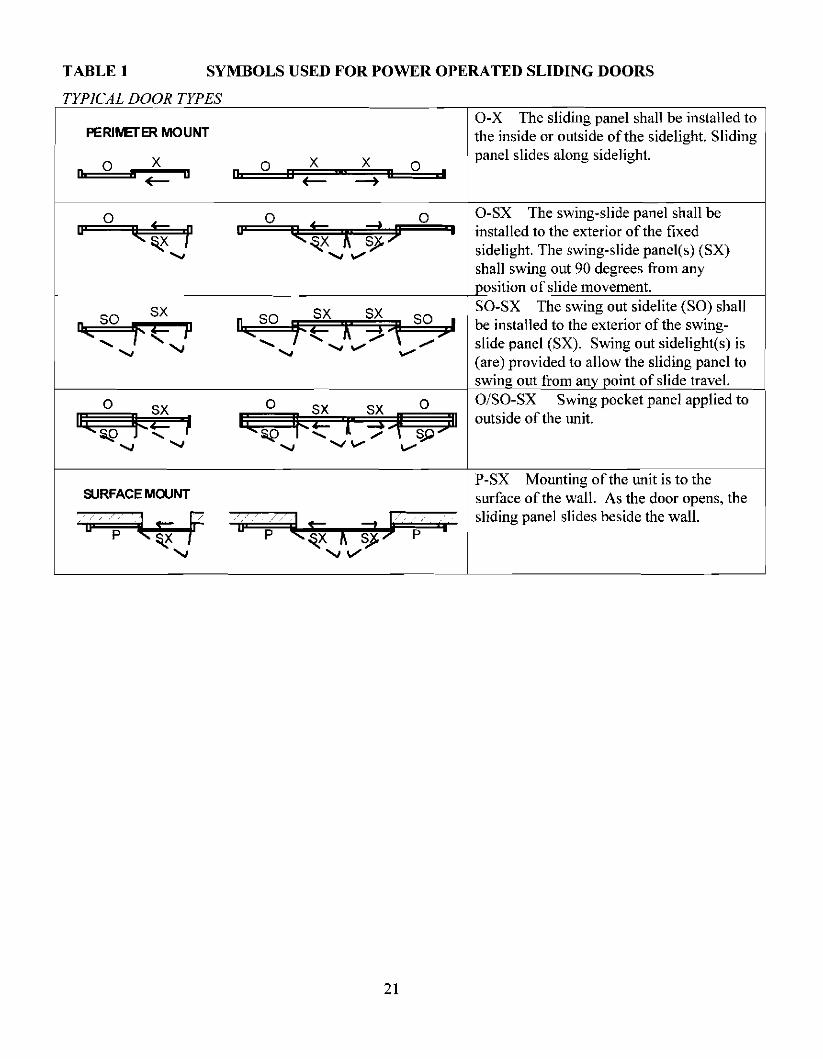
TABLE 1 SYMBOLS USED FOR POWER OPERATED SLIDING DOORS
TYPICAL DOOR TYPES
PERINETER MOUNT
o a X+-0 o a x x a ,
O-X The sliding panel shall be installed tothe inside or outside of the sidelight. Slidingpanel slides along sidelight.
so ,>
oa O-SX The swing-slide panel shall be
installed to the exterior of the fixedsidelight. The swing-slide panel(s) (SX)shall swing out 90 degrees from anyosition of slide movement.
SO-SX The swing out sidelite (SO) shallbe installed to the exterior of the swingslide panel (SX). Swing out sidelight(s) is(are) provided to allow the sliding panel toswin out from an oint of slide travel.O/SO-SX Swing pocket panel applied tooutside of the unit.
P-SX Mounting of the unit is to theSURFACE MOUNT surface of the wall. As the door opens, the
L-_C__p__t_w_x_"'-l_f_/__·_t_"._" p_J ,Iidi', pm,1 ,I;d" be'id, <h, w.IL
21
onve mc es 0 mm mUlplV
Door Opening Min. Width Activating Safety Mat Safety MatSize Required Side - Min. Min. Length Min. Lengthill. lU. Length 3 in. Threshold 1in. Threshold
ill. ill. ill.
36 26 43 36 Y. 37 Y.37 27 43 36 Y. 37 Y. CENTER42 32 43 42 Y. 43 Y. PIVOT43 33 43 42 Y. 43 Y. SINGLES44 34 43 44 Y. 45 Y.45 35 43 44 Y. 45 Y.48 38 43 48 Y. 49 Y.49 39 43 48 y. 49 Y.
48 38 43 24 Y. 25 y. CENTER50 40 43 24 Y. 25 Y. PIVOT60 50 43 30 Y. 3I Y. PAIRS62 52 43 30 Y. 31 Y.72 62 43 36 y. 37 y.74 64 43 36 Y. 37 Y.84 74 43 42 Y. 43 Y.86 76 43 42 Y. 43 Y.
36 26 43 41 Y. 41 Y. BUTTHINGE &
42 32 43 47 Y. 47 Y. OFFSET44 34 43 49 Y. 49 ',4 PIVOTS48 38 43 53 Y. 53 Y. (SINGLE)
48 38 43 29 Y. 29 Y. BUTTHINGE &
60 50 43 35 Y. 35 Y. OFFSET72 62 43 41 y. 41 Y. PIVOTS84 74 43 47 Y. 47 Y. (PAIRS)
TABLE I-A MINIMUM EXPOSED MAT SIZES FOR SWINGING DOORS (See 7.2)To crt· h t If 1 b 25 4
22
APPENDIX A (NOT PART OF A156.10)
APPENDIX A
FIGUREA·1 (Ref. 7.2.1,7.22 & 72.4)CONTROL MATLAYOUTS FORONE·WAYTRAFFIC BUTTOROFFSETPIVOTED SWIIIG DOORS.
S'(127mntM'\X.
THRffiHOo.D
DOOROP8IIING
AC~IATING
I/
5"(1271ml) 5' (127mrTilMAX M'\X.
DOOR OPENI NG
M IIIMJM REQUIREDE JPOSEOW [J"H S'(127mntMAX.
5' (127mntMI N. 5' (127mnjMI N.
~Sl~NG~L'""E"":D~OD"":R'""""::=::':J----- --l--lp""AlllllRUlJJollllllllFDUlJJollllollllR"=s=========:::1J---.-
(BUTT o ROFFSETPlVOTS) (BUTT o ROFFSlET PIVOTS)
FIGUREA·2 (Ref. 7.2.1,7.22,7.23,7.2.4& 6.1.1)CONTROL MATLAYOUTS FORTWD-WAYTRAFRC(IIIGRESSI EGRESS)BUTT OROFFSET PIVOTEDSWIIIG roORS.
GUIDE RAlLS
M'\XJM UM INACTIVE AREA3-314' (95mnj REF.FIGUREA-Q
SINGLEDODR(BUTT OROFFSlETPIVOTS)
23
12~

APPENDD< A (Continued)
FIGUREA-3 (Ref. 7.2.1,7.22 &72.4)CONTROL MATLAYOUTS FOR 0 NE-WAYTRAFFIC CENTERPIVOTED SWNG DOORS.
5' (121m1llMI\X.
THREBHa-O
DOOR OPINING
r'NMUM~WI~1I "
AGnIATING
SINGLEOODR(CENTER PIVOT)
//
5" (127mm) S'(127mrrtMAX MI\X.
DOOROPINING
AGnIATING
I/ \
/ \/ SAfElY \
/ "/ "
PAIROFOOORS(BlJTT 0 ROFFSET PIVOTS)
DOOR<PENING
5' (l27mIllMAX.
5' (127mIllMI N.
FIGUREA-4 (Ref. 6.1.1,7.2.3 & 72.4)CONTROL MATLAYOUTS FORTWo-WAYTRAFFIC (NG RESSI EGRESS)CENTERP1VOTEDSWNG DOORS.
THREBHa-O
SIMNGDOOR
SINGLEOODR(CENTER PIVOT)
24
MI\)(IMUMINACTIVE AREA3-314' (95mIII REF.FIGURE A- 9.
12-1

" (127mm)
43" (1092mm) MIN.ACTIVATIN REQUIRED (f)
EXPOSr LENGii'i
SI°"ccNC=G-'-LE=-=SL:-:-ID=-:E='DOOR
5" (127m
II PANICII BREAKAWAY
t43" (1092mm) MIN.
REQUIRED CM
~~~~~~~======:;~J:r LENG
I
APPENDIX A (Continued)
FIGURE A-5 (Ref. 7.3.1 and 7.3.2)CONTROL MAT LAYOUTS FORSINGLE SLIDE DOORS.
5" (127mm)
ACTIVATING
CLEAR OPENING~--- W1DTII ..
I---MINIMUM REQU'l',.fD~ II EXPOSED WID
II PANICII BREAKAWAY
5" (127mm
FIGURE A-6 (Ref. 7.3.1 and 7.3.2)CONTROL MAT LAYOUTS FORBIPARTING SLIDE DOORS.
BI-PARTING SLIDE DOOR
(1) SEE 7.3.3 FOR ONE-WAY TRAFFICEXPOSED LENGTH IS 24" MINIMUM 12-6-04
25
APPENDIX A (C01timsd)
CONTRa... MATSCROSS SECTIONS.
6" 152mm MAX. INACTIVE WIDTH
CROSS SECTION atTHRESHOIJ)
2-1/2" (64mm) MAX. NACTIVEAREA WHEN MATS ARE
PERPENDICUlAR 10OPENNG
FIGUREA-7(Ref. 7.5.3)
FIGUREA-8(Ref. 7.5.1)
PLAN VlEW- PERPENDICUlAR MATS
PLAN \/IEW- PARALLEL MATS
CROSS SECTION A-A at JONT
3-3/4" (95mm) MAX. NACTIVEAREA WHE N MATS AREPARALLEL TO OPENING
CROSS SECTION B-B at JONT
FIGUREA-9(Ref. 7.5.2)
EXPOSE D AREA
MIN. RAMP LENGTH ACllVE4 x MATTHICKNESS 1-1/2" (38mm)
I-II!-----......... MAX. ~~~-+-.INACTillE
CROSS SECTION atSURFACE MAT TRIM
26
1/2" (13mm) MAT1THICKNESS
FIGUREA-10(Ref. 7.1, 7.5.4, and 7.6.4)
11-1-04

APPENDIX A (Continued)
FIGURE A-11 (Ref. 6.1)GUIDE RAL LAYOUTS FORSV\IINGING DOORS
Q)6' (152mm) MAX.2' (51m m) MIN.
6" (152mm)MAX.
ACllVAllNG
II
I
bAPPROAQ;SIDE
6' (152mm)MAX.
APPROAQ;
ACllVAllNG
(1) SWING DOORIN HALLWAY UTlLlZlNGKNOVVING)('CT ACTIVATING DEVICEMAX 10"WlTHOUTADDING AGUIDE RAIL
SWINGDOOR
30" (762mm)MIN.
I
PANEL
1'::' (152mm) MAX.
WIDTH a= DooRMINIMUM
JAMB I FLOOR MOJNTED
SWING DOOR ---
GUIDERAL ELEVATDNS.
FREE STANDNGI FLOORMOJNTED
PLAN VIEW-ONE-WAYTRAFFIC DOUBLESWIt<G DOORS.
REFER TO FIGUREA-2 FOR GUIDE RAIL LAYOUT INlWO-WAYTRAFFIC(INGRESSI EGRESS)APPLICATON(REF. A-12Aand 6.1.1, EXCEPfON#2).
DOOR WIDTH a= DooR-MINIMUM
11-1-04
27

APPENDIX A (Continued)
FIGURE A-12A( Ref. 8.1 & 82)ACTIlfATtiGANDSAFETY DETECll0NZONES·SWIP«> DOORS.
B
REF. 8.22.2 FOR REQUIREMENT FOR ASAFEW BEAM OR PRESENCE DETECTIONON THE SAFEW ZONE SIDE OF lHE DOOR
30"(762mm)
30"(762mm)
TWO-WACfTRAFFIC
B
ACl1VAl1NG -+---.,...DElECTION ZONE
S'MAX.
A = M N IMUVI ACTIVATING DETECTION ZON E LEN GTH.B =MNIMUVI ACTIVATING DETECTION ZONE WIDTH.C = MINIMUM SAFEW DETECTION ZONE LENGTH.0= MINIMUM SAFEW DETECTION ZONE WIDTH.
A
C
T
30"762mm)
30"(762mm)
30"762mm)
ACl1VAliNG -J---r( DElECTION ZONE
5' (127mm)
..L..1-~~O~N~E~_W~I4;=Cf==:Y~-mrrrTRAFFIC 1--1 ~~~27mm)
MAX.
A
C
A
C
S' (127mm) .-........._..::D~_....--t S' (127mm)MAX. ONE-WACf MAX
TRAFFICNOTE: T HEDETEC110NZONEPAT1ERNS D ER C1EllINTHE AEDIC
~~~~~U~,§~o"r:::'~NOTTOSCAL.E)ANDFOR
11-1-04
28

APPENDIX A (C01timed)
APPENDIX A (C01timed)FIGUREA-12B(Ref. &2.2.3)ACllVATING ANDSAFErYDETECTION ZONES- SWING DOORS WITH DOOR MOUNTEDSENSORS.
B I
~-~-~// \',J \
MINIMUM ..------.ACllVAllNG
A DElECTIONI ZONE
I
SWING DOOR
OOORPWOT
GUIDE RAILS
A =MINIMUMACfIVATING DErECTIONZONE LENGTH.B =MINIMUMACfIVATING DErECTIONZONE WIDTH.C =SAFErY DETECTION ZONE DEPTH B~EDON PERFORI'v'I6.NCED =MINIMLM SAFErY DETECTION ZONE WIDTH.
NcrrE: 0 ElECTIClIIZDNES 0 ERCTEDI NTHE AIDRAIllANGSAREAP~DJlMA1E(NOTTO :rAUAND FORI LLUsrRAlIONP URFOlESONLY.
29

APPENDIX A (Cmtimed)
FIGUREA-12C (Ref. 8.23)ACTIVATING ANDSAFETYDETECTlQII.I ZQII.IES- SWING DOORS WITH DOOR MOUNTEDSENSORSTWO-WAY TRAFFIC.
B I
30"(762mm)
8"
r.:1 5" (127mm MAX.
A
~~..~,1l' ",I ,
, '..---.......MINIMUMACllVAllNG IDElECTION
ZONE
TC
SWING DOOR
DOOR PIVOT
~~I>' "::>~ ~
../
GUIDE RAILS
55" (1397mm)MINIMUM
I
L "I--.;;a_........'
B
TWO-WAYTRAFFIC
A = MINIMUMACTIVATING D ETECTION ZONE LENGTH.B = MINIMUMACTIVATING D ETECTION ZONE WIDTH.C = 55" MINIMUMACTIVATING DETECTION ZONE & GUIDE RAIL LENGTH.
SEE FIGUR:A-12B FOR SAFETY ZONEDIMEt-510t-5.
NOTE: 0 ElECTlOIIZCNES 0 ERCTElJI NTHE AlDIEDRAVIANGSAREA PFROllMAlE(NOTTO s;ALE)ANDFORlLLusrRAllONP URFOlESCNLY.
30

APPENDIX A (C01tim.ed)
FIGUREA-13 (Ref. 8.2)ACTIVATING DETECTIONZONES-SUDE DOORS
r~I SLIDING I \\~ SLIDING
PANEL PANEL
I \\I \ ~
\
A =MINIMUM ACTIVATING DETECTION ZONE LENGTH.B =MINIMUM ACTIVATING DETECTION ZONE WIDTH.
TWO-WAY TRAFFIC
cD REFER T08.3.3 FOR ONE-WAY TRAFFIC
5" (127mm) MAX.
-;[]5" (127mm) MAX.-- i----;
__ Cl
MINIMUMAC11VAllNG
DElECTION ZONE
A
\\ I
-~--'-'------"""'-- .-.r-L,----
cD A
FIXEDPANEL
B
NOTE: D ElECfICl'lZONES D ERCfEDl NTHE AID\EDRAIMNGSAREA PFROllMAlE(NOT TO s::ALE)AND FORI ll.usrRA1l0NPURFOlESONly. 11-1-{)4
31

APPENDIX A (Contilued)
FOUlNG DOORS PANEL LAYO UT
FigureA-14(Ref. 5.0)
SINGLE Fa.DlNG DOrn
FS
PAIR OF FOLDNGDOORS
FS= FOLDSWING PANEL
FX= FOLDSLIDEPANEL
FS
GUIDE RAL LAYOUTS FOR FOLDNG DOORS
FigureA-15(Ref. 6.2)
PAIR OF FOLDNGDOORS
''A"
M~
GL.ideRail
Z'Minimum6" Maximum
SINGLE Fa.D1NGDOrn
~III
"A"Mirirm.m
Z'MinimumG'Maximum
"A" =12 inch.,(305nm),forT'AO Wily
Traffic orOneWayTraffi:approadlilg from theFotJ Side.
or
5 inches,(130mm), for One Wily
Traffic a pproaching from theNon-Fold Side.
JAMB AND FLOOR MOUNlED FREE STANDNG FLOOR MOUNTED
11-1-04
32

APPE NDD< A (Continued)
CONTROL MAT LAYOUTS FOR FOLDING DOORS
FigureA-16
(Ref. 7.4 throug, 7.4.4.)
CONTROL MAT LAYOUT FOR ONE-WAY TRAFFIC FOLDING DOORS
Door Opelirg Door Opelirg- s,l-- -s' - - s' f- - s' I--
tMi Ii mum
Activatirg Req'd ActivatirgExposedLerg1h43"'I
-. -. .....
--
~ 1 ""-
~ ~....
Safely SafelyMilimLrnReq'd
Exposed
t 'T' J,S'Mi~mLrn Mi~mum
SINGLE FQ.DlNGDOCR PAIR OF FOLDING DOOR
CONTROL MAT LAYOUT FOR TWO-WAY TRAFFIC FOLDING DOCRS
DoorOpelirg DoorOpelirg
- S' I-- - s' - - s' f- - S' -f
Activatirg MilimLrn ActivatirgReq'd~osed
yo- ff ~f.y 1
~-
~I \~-
Milimum ff SafelyReq'd
Exposed
• Ler Js' S'
Mi~mum Mi1nun
1Activatirg 43"Min Activatirg
!
11-1-04
33
APPENDIX A (Continued)
DETECTION PATIERN LAYOUTS FOR FOLDING DOORSFigure A-17A
(Ref. 8.4)
----
ONE WAY TRAFFIC WITH APPROACH FROM NON-FOLD SIDE
[
Clear Openmg_ [Clear Openlflg_
4~ . . ~"
Minimum V A~~~:on~ Minimum1·- - .... _.-/ _-- - ... .- ......
~ ~-, ,---f----- ~------T-- --+-rl - - -T - - - - -. -.- - - - - -', - - - - I 30", B" t .. ,5" Max, rr-t:l:.,::---------:::-'-i---+t--T-,.. 5" Max. n ~ - - .. - "'-DI r • .J1 I
H--fl-+-I+-,-1 1-----1 I- .~ 5" Max, I I 1 I
~I /,'- - - - - 1- ~_.__
I III SafetyMat
----- I-
5" Mi~imum
SINGLE FOLDING DOORONE WAY TRAFFIC
SINGLE FOLDING DOORONE WAYTRAFFIC
WITH DOORS CLOSED
rC"~ O~;"g - rClear O~,ening •
4~ I Activation 4~Minimum V Zone ~ MInimumP#--"'_ .../· ,1'- -1IlIo_ ... ,
, ,,;;-... ""
r-----f-----~------r-----30" ---;--- _--1-.-- - - _~ __ - -_I
! 5~ • 8" t \ .T rT"""P[+:,l,;-W---::R:=---"'-_-H~--;-' , :" M1ClX. DI I-+'=-~~- -~
I- WSafety i 5~Max. ~ ~""''''-~-'''''LM. , I
U I Safety Zone ~
, 1... t- - - - - - - -a- - 1-.... - ~ - - .-
.,. ~ 6" 5" Minimj.lm
L .:,. -:-f--:. :. r5~' ~~I2r-:---I I-- - I-5" -..I r- 2<'
~I2::=A=ct=sr=V~=~=i~d=na=a=a=t=:SJ ~_~_"...'_:_~-:-~:-e:-:-~:-~-=-~.:.......e., ~~
SINGLE FOLDING DOORONE WAY TRAFFIC
SINGLE FOLDING DOORONE WAY TRAFFIC
NOlE: DElECTION ZONES DEPICTED IN THE ABOVEll'lAWlf«lS AIlE AI'PROlU MATE tN:JTTO !iCAlE)AND FOO.ILLUIITRATION PURPC6ES I;tllY.
WITH DOORS OPEN 12-6-04

APPENDIX A (Continued)
DETECTION PATTERN LAYOUTS FORFOLDING DOORSFigure A-17B
(Ref. 8.41
30'
J
raea~~~ingl raea~~~in91
Mi ri mum I I Mirimum I----/~,----=~~~~..~ ~~1;~~k'~ ~-_t~--=~----'-t--I• '5',' •• , Max. ~ ,
- - ---. - - - - - - - - -,,- - - -.-.-, - - - - - .. .:- - - - - - - -,-, - -- 30
.. -.. - - - - r ~' r I - - - - t--=-.-----------,"""J+ I
f-+-+Ill----+--,'----------------+l......J-4f--+-i 5"8'J, -j=J=±;:---+:~;-oii~---------~.-----;..---.;-;;;~~+-j,lI I I ... -----, ... -.-
II ! I \ \ II Maxi. - L _1.1;1 - - - - - - - - - -~\1l-
II~I / Safely Mat I
J\III M~'X.:{/ Sa~e1~Zo~ \~
I1 '1 ,
5"Mnimum l" -'" 5"Minimum.- , I, ~ - .. --~.-~ I
~~~ ~~ ~~~PAIR a= fULDlNG DOORS PAIR a= fULDlNG DOORS
ONE WAY TRAFFIC ONE WAY TRAFFIC
WITH DOORSCLOSED
]J
I30'
J
r a:~~in9 "II r aea~~~ing IM~'.mum Miri mum I
_- .. _.... ~ActivatiOO~., __ - po-- _
_ _ eI-::'- _ _ _.:~~ __ -.!ooe ~-:... ~""""~.__
• '5'" •t , Max. ~ ,
-~- ~ - -.::- ~.=-.-:. - -.- -,-1-+1- - - --';-.-:':.:.:-.-:: =-.-,~ - ~
"ir~_~~~~~~~J\' l~i.~ ~ r{~~;i~~~ =5" Minimum 'r ~_ 5" Minimum ':iTr + 12",.- - ..-:.~ ": - -
~, ,~ k-
• aear Door Opering ,24" 5" 5" ._ : Less 10' •
C Secaldary ~ •Activatioo Mat .... SecallBy ,
.. _.. Activali00 Zore.- .- .-l!:::===========::-..J - • - - _ .. '-
PAIR a= FOLDING DOORS
ONE WAY TRAFFIC
PAIR a= fULDlNG DOORS
ONE WAY TRAFFIC
WITH DOORSOPEN
NOTE: DE1ECTIOIIZCNES DERCTEO NTHEAB:l1EDRAVIANGSAREA PFROXMA1E(NOT TO s:ALE)ANDFORJ U.UsrRA~ONPURR:>G;SCNLY 12-8-04
35
APPENDIX A (Continued)
{Rlf!<f.3.4)
ONE WAY TRAFFIC WITH APPROACH FROM FOLD SliDE
DETECTION PATIERN LAYOUTS FOR. FOLDING DOORS
Figure A.170
.
5"Mm.,
SINGLE FOLDING DOOR PAIR OF FOLDING DOORSONE WAYTRAFFfC ONE WAY TRAFFIC
lQ::~t:rgk~::;~~~~c,ea~~£::g:1
' , or - .. ~:~=~) .. _.. _.. .... ~.. _....-- t -I-- , -- --.' -- - 1 --
I ,5' I ,\0 ,Max. I ,-- ---;. - -- ..-- ---. E -- --\-- -- - f-- -- --~- --
.. .... - ~ S" ... ... - .. ...,. - - - • .,...
,,• Activaten• li:oe~ .. ....- ----
- ... ,,----
J. ---W,/~ ---:;:-,-... -H1""T, r ... ~:~.... ___ 't,,\,\:~i 1.'1/ J .. r-s.. """""'t I ~ 1/ - -- '11.....*_-+-I~I Safety Zone t, ~._ Max ~ I S~ Zone _ _ \.lL
.. ... 7 .. "I ....... ~·~I~I~~m.._·1 i I .. - .. _ !!i' Ml mum _ ... _... I
,.. ,. ::.r~ S' r foo' 5"\- t" *' ... .......... -- - - .. ..... -i S' •
, -- -- n 30' " --.- -- -- -- -- --;- -I 48~ Activation, IMinimurn
--4 .. ~:7_-_-_-__-1:__1===_-_-_-WITH DOORS CLOSED
SINGLE FOLDfNG DOOR PAIR OF FOlDING DOORSONE WAY TRAFFIC ONE WAY TRAFFIC
lQ:i~~krgc:=~~agn~c'ear:~~:n: :1
- - (ktFile \!riIh .. -.. .., ... - DocrOpenj ...... - ..........
t - ,--------." --- -- 1
I 5"'5" .. ' •Max. ,Malt I •* ~ --- -- -. r --~..~ ...-'-.........----- ~ , 8" ..... ..... -
,•
.. f.-- --
.--- ... ---- ..... '\11,L..- - - - tl\ \JI:__ SafelyZone __ • \U
.::;==I--+=="'II";::,==+::....;.~=--==:.,-=
'.. S" Mimmum I5"~ .._- ....._'-_..",: ::..15"... ~ ~ ..
t.-,• Activaten• li:oe~ .....~ -- --..... _... _-
..,-,- -- -- 31l" 48"
I~ Activation, IMinimum
---I, .. ~:--=-" -- -l: i===__
3fJ'
WfTH DOORS OPEN
12-6-04
37
APPENDIX A (Contilued)
A-18A (Ref. 8.3.2.1) VERllCAL SECTIC»I· SLDEDOOR SHOW~ ACTIVATNG DETECTION ANDPHOTOELECTRIC BEAM ZC»I ES (4 mirirmm).
ACllVAllNGDElECTION ZONE - 2.5SECONDMN. TIMEDELAY
SLDING
DOORPANE~
I
/;/o
B
3" (16m m) MAX. FROMCENTERUNE OFSLDING PANEL
TOP PHOTOELECTRIC BEAMLOCATED BElWEEN55" (1397mm) AND45" (1143mm)
OTHER BEAMS LOCATEDNOT GREATER THAN6' (152) -12" (305mm) APART
BOTTOM PHOTOELECTRICBEAM LOCATED BETWEEN28" (711mm) AND 6' (152mm)
A =MAXIMUIII DISTANCE 10 ACTWAllNGDETECllON ZONEB =43" MINIMUIII
A-18B (Ref. 8.3.2.2) VERTICAL SECTION - SUDE DOOR SHOWNG ACTIIIATING AN 0PRESENCE oElECTION ZONE lHROUGl DOOR OPENNG.
ACllVAllNGDElECTION ZONE 1.5SECONDMN. TIMEDELAY
PRESENCEDElECTION ZONE
SLDINGDOOR PANEL
NOTE: 0 ElECTIOIIZONES 0 ERCTEDI NTHE AEDIEDRAWNGS ARE A PFROJIMA1E(NOT TO s::ALE)AND FORI LLusrRA]ONP LJRR:)!ESCNLY.
C
PHOlOELECTRIC BEAMSAS SHO\I\INARE REQUIRED IF PRESENCEDElECTION ZONE IS DEACTIVATED WHENDOOR STARTS TO CLOSE.
TOP PHOTOELECTRIC
~BEAM LOCATEDBETWEEN
I 55" (1397mm) AND,ri.If--.C<-".¥'It4H70'-+------·/ 45" (1143mm)
BOTTOMPHOlOELECTRICBEAM LOCATEDBETWEEN
1--1T',"'TSQHHH'-h'7f'--.J 28" (711mm) AND6' (152mm)
A = MAXIMUIII D ISTANCE 10 ACTWA11NG DETECllON ZON EB =MNIMUIII PRESENCE DETECTION ZONE WDTH (SEE 8.3.2.2)C = 43" MINIMUIII
12-6-04
38
APPENDIX A (Continued)
A-1lC (Ref. 8.32.3) VERTlCALSECTlON· SLDE DOOR SHOWIPG ACTlVATlNGANDPRESENCE DETECTIONZONE ON EACHSDE OF DOOR.
ACllVAllNGDElECTION ZONE 1.5SECONDMN. TIMEDELAY
PRESENCEDElECTION ZONE
SLDINGDOOR PANEL
C
PHOlOELECTRIC BEAMS AREREQUIRED F PRESENCE DElECTIONZONE IS MORE THAN 3" FROM FACE OFDOOR
TOP PHOTOELECTRICBEAM LOCATEDBETWEEN55" (1397mm) AND45" (1143mm)
BOTTOMPHOlOELECTRICBEAM LOCATEDBETWEEN28" (711mm)AND6" (152mm)
A = MAXIMllv'I DISTANCE 10 ACTWAllNG DETECll0N ZONEB = MAXIMllv'I DISTANCE 10 THE PRESENCE DETECTION ZONE (SEE 8.3.2.3)C= 43"MINIMllv'I
A-llD (Ref. 8.32.4) VERTlCALSECTlON· SLDE DOOR SHOWIPG ACTIVATING D ETECTION ANDPHOTOELECTRIC BEAMONE SIDEANDPRESENCE DETECTION ZONE ONOTHERSIDEOF DOOR.
ACllVAllNG =~-;::;--.,F;.«f;)DElECTION ZONE - 2.5SECONDMN. TIMEDELAY
PRESENCEDElECTION ZONE
SLDINGDOOR PANEL
C
NOTE: D ElECTIOIIZCNES DERCTECl NTHE AlDIEDRAINNGS ARE A PFROl4MAlE(NOTTO s::Al.E)ANDFORILLusrRAlIONP URFO:'ESONLy.
3' (76mm) MAX. FROMCENTERUNE OF SUDNGPANEL
TOP PHOTOELECTRICBEAM LOCATEDBETWEEN55" (1397mm) AND45" (1143mm)
BOTTOMPHOlOELECTRICBEAM LOCATEDBETWEEN28" (711mm) AND6" (152mm)
A = MAXIMllv'I DISTANCE 10 ACTWAllNG DETECll0N ZONEB = MAXIMllv'I DISTANCE 10 THE PRESENCE DETECTION ZONE (SEE 8.3.2.4)C = 43" MINIMllv'I
12-6-04
39
APPENDIX A (Continued)
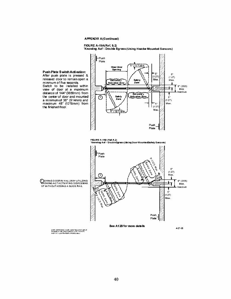
FIGURE A-19A(Ref. 9.2)'Knowing Act' - Double Egress (Using Header Mounted Sensors)
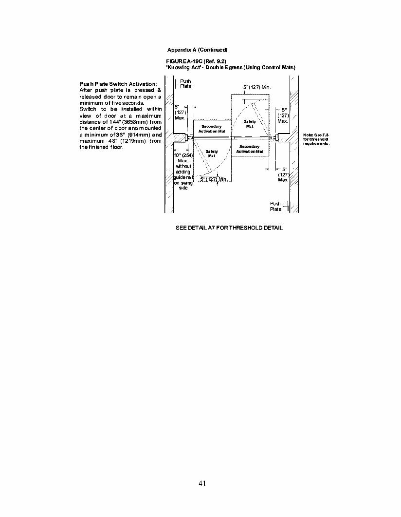
Push Plate SVlAtchActivation:After push plate is pressed &released door to remain open amirimum offive seconds.Switch to be installed withinview of door at a maximumdistance of 144" (3658mm) fromthe cerier of door and mounteda minimLlTl of 36" (914mm) andmaximLlTl 48" (1219mm) fromthe finished floor.
Clear DoorOpenng
FIGURE A-19B (Ref.9.2)'Knowing Ad'- DoubleEgr.s (Using Door MountedSafelySensors)
(i)SWlNG D OORIN HALLWAY UTIUZING ~~~~~i=~~!if'=~le=~~~~~~~~i;J;;T8" (203)~OWINGACTACTfliATINGDEVICEMAX.E Max.10" WITHOUT ADDING A GUIDE RAIL Inactive
see A12Bfor more details4-27-05
NOTE· DETECTION ZONES 0 S'ICTEDI N"THE AIPVEDRAWINGS AFE AFPROXIMATE (NOTTOSCALEjAt>{) FOR I LLUSTRATlONPURR:>SESONLY
40


AFPB\lDIX B
FIGUREB-5(Ref,11,)SIGNAGE FORAUTOMA.TIC FO-DINGDOORS,
DECAL FOR
©AU. AUTO-
f) I AUTOM'>l1 C o OCR IMATICDOORS
@DECAL FORONE-WAY
DECAL FOR TRAFFIC APPROACH SlOE NON-APPRQl\CH SlOE
'KNOWING ®ACT DOORS
©DECAL FOR ©FOLDNG DOORS DECAL FORWITH SWINGING 8 IN EMERGENCY TWO-WAYPPNELS PUSH TO CPB\l TRAFAC NON.f'OLO SlOE FOLD SlOE
FIGUREB-$(Ref,11,)INTERIOR VIEW (FOLD SIDE) - TYPICAL FOLDING DOOR WITH APPROPRIATE SIGNAGE FORTWO-WAY TRAFFIC,
DE CAL C EN TERE 0BETWEEN 36"MIN,ANO 6 a'MAX, (914ANO 1524mm)ABOVEFIN ISH FLOOR
J
/ ""/ ""v
~~ ~~r-- - """''" ""...0 (CJ (CJ ...
/ IIIN EMBGENCY T 1:N EMElGENct~PUSH 100PEN PUSH TOOPEN
V- A ] .~••<OO. 1(B A ].~••<oo. I(B "" ~ ~
/
ENTEREOAT "" /73:: 127mm)
"" /SHFLOOR
I FS ""FX FX/ FSPPNEL P~ ~EL PPNEL
,,1/
DECALS C58'.5"(14ABOVEFltII
NOTE: T HEORAI/II NGS 0 El'ICTEOA IDVEAREAPPROXIMIQ"E(NOTTOSCALE)ANOFOR IIJ.USI"RAlI ON PURR:>SIEONLY
11-1-04
44


These should be countered by additional caution signage or sensors, restricting traffic, or reducing thedoor speed in both opening and closing. Activating zone, opening and closing force, speed, and safetyzone requirements should be considered.
49