B.F.oodrch Arospce &Defese Podud - NASA Contract No. NAS-9-12049 DRL No. Exhibit "A" Line Item No. 9...
43
(NASA-CR-134128) ENGINEERING REPORT. N74-11306' PART 1: NASA WHEEL AIR SEAL DEVELOPMENT FOR SPACE SHUTTLE TYPE ENVIRONMENTAL REQUIREMENTS (Goodrich (B. F.) Co.) Unclas 43 p BC $4.25 CSCL 11A G3/15 22833 B.F.oodrch Arospce &Defese Podud https://ntrs.nasa.gov/search.jsp?R=19740003193 2018-06-16T08:02:34+00:00Z
Transcript of B.F.oodrch Arospce &Defese Podud - NASA Contract No. NAS-9-12049 DRL No. Exhibit "A" Line Item No. 9...

(NASA-CR-134128) ENGINEERING REPORT. N74-11306'
PART 1: NASA WHEEL AIR SEAL DEVELOPMENT
FOR SPACE SHUTTLE TYPE ENVIRONMENTAL
REQUIREMENTS (Goodrich (B. F.) Co.) Unclas
43 p BC $4.25 CSCL 11A G3/15 22833
B.F.oodrch Arospce &Defese Podud
https://ntrs.nasa.gov/search.jsp?R=19740003193 2018-06-16T08:02:34+00:00Z

NASA Contract No. NAS-9-12049DRL No. Exhibit "A"Line Item No. 9DRD No. MA-129T
ENGINEERING REPORT NO. 4239NASA Wheel Air Seal Development
forSpace Shuttle Type Environmental
RequirementsJanuary 23, 1973
PART I
B.F.GOODRICH AEROSPACE & DEFENSE PRODUCTS
Wheel and Brake Plant
Troy, Ohio
Chi. ef. SundermanChief Engineer

ER-4239FSC 97153
PRECEDING PAGE5BLANK NOT FILMED
ABSTRACT
NASA WHEEL AIR SEAL DEVELOPMENT
The investigation covers the sealing techniques required for existingaircraft wheel-tire designs to meet the hard vacuum 10- 5 torr andcold temperature -65 0 F requirements of space travel. The investi-gation covers the use of existing wheel seal designs (AerospaceStandard AS666A and Military Standard 33649) along with an Omniseal®design consisting of a flat helical spring inside a 0 -section teflonring.
V

ER-4239 PRECEDING PAGE BLANK NOT FILMEDER -4239FSC 97153
TABLE OF CONTENTS
Page
DISTRIBUTION LIST iii
ABSTRACT v
TABLE OF CONTENTS vii
INTRODUCTION 1
CONCLUSIONS 2
RE COMMENDATIONS 2
PURPOSE AND SCOPE OF INVESTIGATION 2
ENVIRONMENTAL REQUIREMEN TS 3
DISCUSSION OF RESULTS 4 thru 9
Split Wheel Air Seal 4 thru 6Inflation Valve and Fuse Plug Seals 7NASA Environmental Testing of Wheel and Tire 8AssemblyTest Results 9
REFERENCES 10
APPENDIX A - Cold Temperature Testing (-65 0 F) A-i thru A-21of Wheel Air Seals
APPENDIX B - NASA Environmental Testing of Wheel B-1 thru B-6and Tire Assembly
Written by:L. D. Bok
Checked by:
vii

ER-4239FSC 97153
INTRODUCTION
Existing aircraft type wheel-tire designs are being considered for useon the space shuttle. Previous environmental testing of a F4J wheeland tire assembly to the space shuttle type environment showed thatthe air seals for the split wheel and fuse plug leaked. 1 The air leakagerate over the long term mission would cause the shuttle to land onseriously under-inflated tires. This investigation covers the evaluationand improvement of the sealing techniques for the split-wheel, fuseplug, and inflation valve.
1
ER-4239FSC 97153
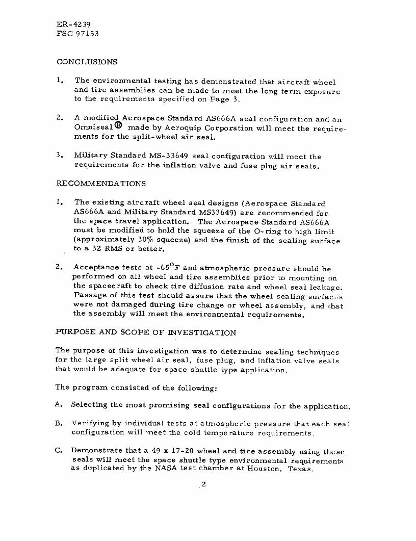
CONCLUSIONS
1. The environmental testing has demonstrated that aircraft wheeland tire assemblies can be made to meet the long term exposureto the requirements specified on Page 3.
2. A modified Aerospace Standard AS666A seal configuration and anOmnisealO made by Aeroquip Corporation will meet the require-ments for the split-wheel air seal.
3. Military Standard MS-33649 seal configuration will meet therequirements for the inflation valve and fuse plug air seals.
RE COMMENDATIONS
1. The existing aircraft wheel seal designs (Aerospace StandardAS666A and Military Standard MS33649) are recommended forthe space travel application. The Aerospace Standard AS666Amust be modified to hold the squeeze of the O-ring to high limit(approximately 30% squeeze) and the finish of the sealing surfaceto a 32 RMS or better.
2. Acceptance tests at -65 0 F and atmospheric pressure should beperformed on all wheel and tire assemblies prior to mounting onthe spacecraft to check tire diffusion rate and wheel seal leakage.Passage of this test should assure that the wheel sealing surfaceswere not damaged during tire change or wheel assembly, and thatthe assembly will meet the environmental requirements.
PURPOSE AND SCOPE OF INVESTIGATION
The purpose of this investigation was to determine sealing techniquesfor the large split wheel air seal, fuse plug, and inflation valve sealsthat would be adequate for space shuttle type application.
The program consisted of the following:
A. Selecting the most promising seal configurations for the application.
B. Verifying by individual tests at atmospheric pressure that each sealconfiguration will meet the cold temperature requirements.
C. Demonstrate that a 49 x 17-20 wheel and tire assembly using theseseals will meet the space shuttle type environmental requirementsas duplicated by the NASA test chamber at Houston, Texas.
2

ER-4239FSC 97153
ENVIRONMENTAL REQUIREMENTS
The wheel and tire exposed to a pressure of 10 - 5 torr and a temper-ature of -650F for a period of seven days must not lose more than 5%of the original tire pressure. (Corrected for temperature andpressure to standard day readings). Ref. NAS-9-12049 Specification,Exhibit "A", Paragraph 3. 3. 1 4
Review of Environmental Requirements
The environmental requirements for the space shuttle produce twosealing problems for the wheel seals.
1. Sealing a Hard Vacuum
The problems involved in sealing a hard vacuum are sublimationof conventional elastomer and gas permeability of the elastomer.The sublimation of the elastomer results in loss of body weightand possible change in physical properties of the seal. Thesublimation of the seal can be controlled by the seal geometryfor only those molecules on the surface are moved. The gaspermability can be minimized by selection of the elastomer.
2. Sealing at -65 0 F
The problems involved in sealing at -65 0 F are the interactionsbetween the coefficient of thermal expansions, the resilience ofthe elastomer or seal at cold temperatures, and the finish of thesealing surfaces. An elastomer seal seals on its ability tofollow the contour of the mating sealing surface filling its voids.As the temperature decreases, the seal loses its resilience orability to follow the contour of the mating sealing surface. Ashift in the seal contact area due to change in temperature andthe differences in thermal expansion could cause leakage.
3

ER-4239FSC 97153
DISCUSSION OF RESULTS
Split Wheel Air Seal
Two split wheel air seals were selected based primarily on the cold
temperature requirements.
1. Aerospace Standard AS666A
Aerospace Standard AS666A shown in Figure 1 is a specification
for seal cavity design for static seals used in aircraft tubeless
tire wheels. This design was selected as the best O-ring type
seal configuration based on past aircraft wheel experience. The
O-ring compound selected was Parker Seal Compound E600-7
with a hardness of 70 Shore A. This compound is basically an
ethylene propylene selected for its temperature range of -65 0 F
to 300 0 F. The compound is not specifically designed for high
vacuum properties but satisfactorily passed the space shuttle typeenvironmental requirements.
Deta ilView
020 Min r. 025 Max. Gap
Rad.
(300 - 600+ 1/20.020 Min. Rad s /
.020 Max. RDiametral Gap
. 020 Min.Radius
Figure 1Aerospace Standard AS 666A
4

ER-4239FSC 97153
DISCUSSION OF RESULTS (CONT'D)
1. Aerospace Standard AS666A (Cont'd)
The modified Aerospace Standard AS666A seal configuration passedall cold tests at -65 0 F with only minor leakage when a rapid temper-ature fluctuation occurred. (Test results are listed in Appendix A).The temperature fluctuation was caused by opening the test chamberdoor for 15 to 20 minutes after the test chamber had stabilized at-65 0 F. The leakage stopped once the temperature stabilized. Allsealing surfaces for these tests were 32 RMS or better. O-ringsqueeze ranging from 15% to 32% passed the requirements.
2. Aeroquip Corporation Omnisealw
The Omniseal consists of a flat helical spring inside a C; -sectionteflon ring as shown by Figure 2. This design was selected forboth its stability in a hard vacuum, (Stable to pressu e of 10-7
torr)2 and its temperature range of -4230F to 5000F.
-j
The Omniseal consists of a flat helical spring inside a Omniseals are permanently resilient and provide (A)C-section Teflon ring. Pressure actuated. . .system high unit loading of sealing surfaces, (B) flat heel-to-
pressure enters inside of Omniseal and produces a "pres- gland support which assures stable positioning of sealsure to pressure" seal that is self compensating as pres- to prevent roll out. A flat, ribbon-type internal spring,sure increases, decreases or impulses. (C) assures maximum seal support and reliability of
performance.
Figure 2
Aeroquip Omniseal
5

ER -4239FSC 97153
DISCUSSION OF RESULTS (CONT'D)
2. Aeroquip Corporation Omniseal® (Cont'd)
The Omniseal, when tested with the seal cavity specified by AeroquipCorporation as shown in Figure 3, passed the -65 0 F temperaturerequirement. (Test results are listed in Appendix A.) A rapid tem-perature fluctuation did not cause leakage with the Omniseal as itdid with the Aerospace Standard AS666A configuration. The testdemonstrated that the Omniseal could be made to meet the coldtemperature requirements. This investigation did not attempt todefine the design criteria for the Omniseal. This design criteriashould be specified by Aeroquip Corporation for each seal size andapplication.
L'Y'-- \
18.450DIA.
18.440.020.030
'_.2_. I
./87 .
Figure 3Split-Wheel Omniseal Seal
6

ER-4239FSC 97153
DISCUSSION OF RESULTS (CONT'D)
Inflation Valve and Fuse Plug Seals
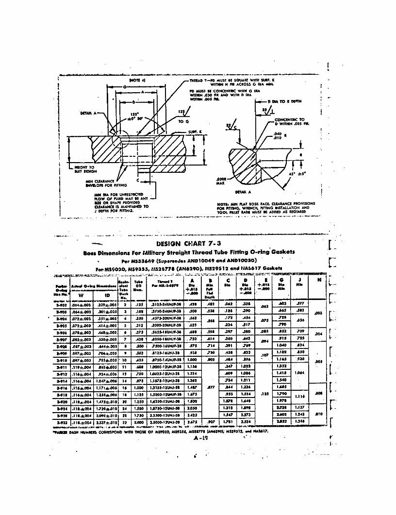
The seal configuration selected for the inflation valve and fuse plug sealswas the MS-33649. This seal configuration is the military boss specifi-cation for straight thread tube fitting O-ring gaskets. This configurationwas selected for its confinement of the O-ring.
The O-ring selected was molded to MS-28778 dimensions by PrecisionRubber Products Corporation with their Compound 7377.
The seal configuration when tested with the MS-33656 flared tube con-nection or MS-9015 machine thread O-ring seal, as shown in Figure 4,passed the cold temperature requirements. (Test results are listed inAppendix A.)
MS-9015 Machine MS-28778 O-RingThread O-Ring Seal
MS-33649 Straight TubeFitting O-Ring Gasket
Figure 4Inflation Valve and Fuse Plug Seal Configuration
7
ER -4239FSC 97153
DISCUSSION OF RESULTS (CONT'D)
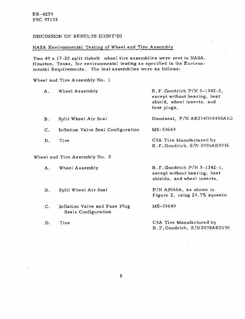
NASA Environmental Testing of Wheel and Tire Assembly
Two 49 x 17-20 split tiebolt wheel tire assemblies were sent to NASA,Houston, Texas, for environmental testing as specified in the Environ-mental Requirements. The test assemblies were as follows:
Wheel and Tire Assembly No. 1
A. Wheel Assembly B.F. Goodrich P/N 3-1342-2,except without bearing, heatshield, wheel inserts, andfuse plugs.
B. Split Wheel Air Seal Omniseal, P/N AR214DI8450AIQ
C. Inflation Valve Seal Configuration MS-33649
D. Tire C5A Tire Manufactured byB.F.Goodrich, S/N 2098AK0736
Wheel and Tire Assembly No. 2
A. Wheel Assembly B.F.Goodrich P/N 3-1342-1,except without bearing, heatshields, and wheel inserts.
B. Split Wheel Air Seal P/N AS666A, as shown inFigure 2, using 29. 7% squeeze.
C. Inflation Valve and Fuse Plug MS-33649Seals Configuration
D. Tire C5A Tire Manufactured byB.F.Goodrich, S/N2098AK0190
8

ER -4239FSC 97153
DISCUSSION OF RESULTS (CONT'D)
Test Results
Both wheel assemblies passed the environmental testing at NASA. Theenvironmental testing lasted for a period of 184 hours from the time thepressure and temperature in the test chambers started dropping untilthe time and tire temperature stabilized at room temperature at the endof the test. Wheel and tire assemblies Nos. 1 and 2 lost 1. 0% and 1.25%of the original tire pressure respectively during this test period. Theallowable pressure loss was 5% of the original tire pressure. (Testresults are listed in Appendix B.)
9
ER-4239FSC 97153
REFERENCES
1. NASA Manned Spacecraft Center, Thermochemical Test AreaDocument No. MSC-03884.
2. The Effects of Space Environments on Insulation of Teflon® TFEand FEP Resins - C. E. Jolley & J. C. Reed, December 1962.
3. Aeroquip Corporation Bulletin 299, Copyright 1966.
4. NASA Manned Spacecraft Center, Contract NAS-9-12049, Exhibit "A."Lightweight Wheel and Brake Subsystem.
10
ER -4239FSC 97153
APPENDIX A
COLD TEMPERATURE TESTING (-65 0 F)OF
WHEEL AIR SEALS
ER-4239FSC 97153
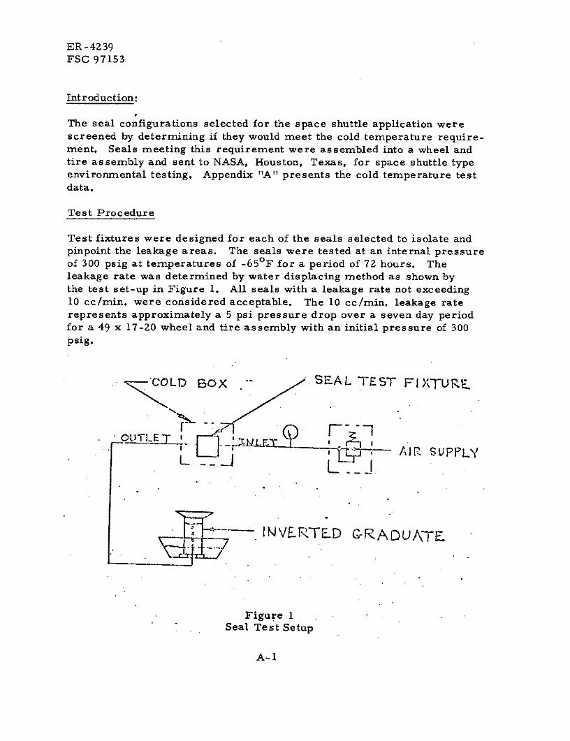
Introduction:
The seal configurations selected for the space shuttle application werescreened by determining if they would meet the cold temperature require-ment. Seals meeting this requirement were assembled into a wheel andtire assembly and sent to NASA, Houston, Texas, for space shuttle typeenvironmental testing. Appendix "A" presents the cold temperature testdata.
Test Procedure
Test fixtures were designed for each of the seals selected to isolate andpinpoint the leakage areas. The seals were tested at an internal pressureof 300 psig at temperatures of -65 0 F for a period of 72 hours. Theleakage rate was determined by water displacing method as shown bythe test set-up in Figure 1. All seals with a leakage rate not exceeding10 cc/min. were considered acceptable. The 10 cc/min. leakage raterepresents approximately a 5 psi pressure drop over a seven day periodfor a 49 x 17-20 wheel and tire assembly with an initial pressure of 300psig.
COLD BOX - SEAL TEST FIXTURE.
L __.
LOUTL I_
-~T
IMVEJTED C-RADU -FrE
Figure 1Seal Test Setup
A-1
ER-4239FSC 97153
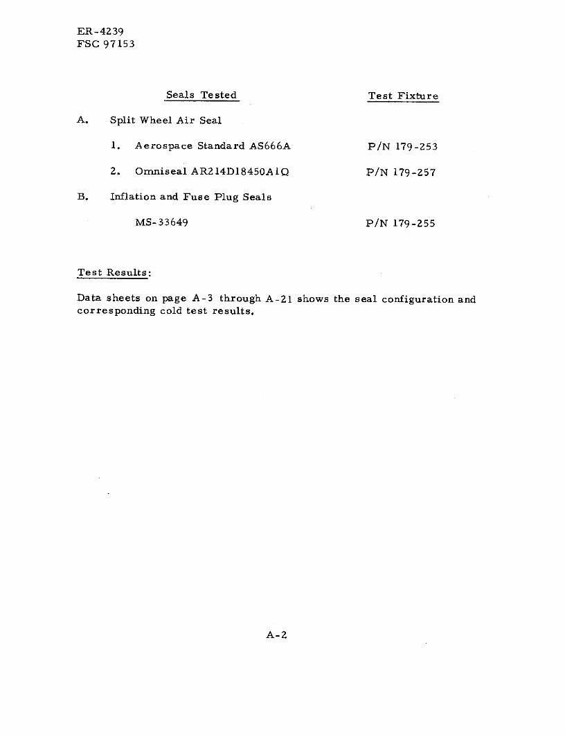
Seals Tested Test Fixture
A. Split Wheel Air Seal
1. Aerospace Standard AS666A P/N 179-253
2. Omniseal AR214DI8450A1Q P/N 179-257
B. Inflation and Fuse Plug Seals
MS-33649 P/N 179-255
Test Results:
Data sheets on page A-3 through A-21 shows the seal configuration andcorresponding cold test results.
A-2

'-44' 35'
S .000 .113
18. 510 Aerospace Standard AS666AConfiguration for Test 1 and 2Date - 11-10-72
Test Fixture P/N 179-253, Chg.18. 506 O-Ring P/N 68-185 Dia. .210
A-3

Data Sheet No. 1
Test No. 1 Date 11-10-71
Seal 68-185
Compound Parker E600-7 Hardness 70 Shore A
Test Fixture P/N 179-253 Change ---
O-Ring Squeeze 32. 8%
Time Tem erature LeakageHrs. F Rate cc/m n Comments
0 Ambient
23 -65
42 -65 - Opened Cold Box for 20 Minutes
44 -65 --- Opened Cold Box for 20 Minutes
44 Hrs.20 Min. --- .8 16 cc/20 min.
45 --- 1.0 16 cc/15 min.
48 --- Nil Stopped Test
Repeat d Test
0 Ambient ---
64 -65 --- 1 cc/ 6 4 hrs.
65.5 -65 --- Warm Box
+15 min 30 ---
+2.5 mir --- -- - Turned Cold Box On
+5 min --- 2.2 11 cc/5 min.
70.0 -65 --- 1 cc/4 hrs.
A-4

Data Sheet No. 2
Test No. 2 Date 11-17-71
Seal 68-185 (Repeat with New Seal)
Compound Parker E600-7 Hardness 70 Shore A
Test Fixture P/N 179-253 Change ---O-Ring Squeeze 32. 8%
Time Tem erature Leakage
Hrs. F Rate cc/m n Comments
0 .A mbient ---
18 -65 0
23 Ambient 0
Repeat d Test
0 Ambinent 0
26 -65 0 Disassembled to Replace Outer O-Ring
Repeat d Test
0 Ambient 0
2.0 Ambient --- 16 cc/1. 5 hrs,
5.0 -65 ---
25.0 -65
29.0 -65 --- Turned Heat on for 15 Minutes
+15 --- --- Turned Cold Box On
46 -65 --- Stopped Test
A-5
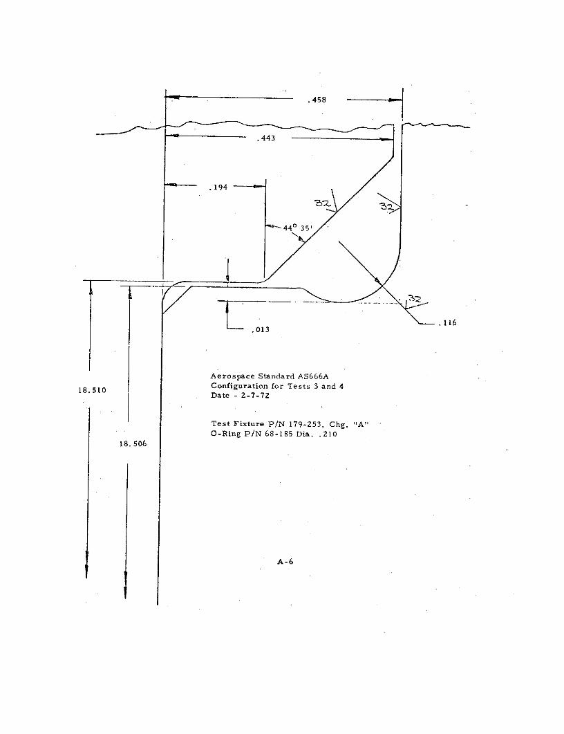
440 3 5'
.116.013
Aerospace Standard AS666A
18. 510 Configuration for Tests 3 and 4Date - 2-7-72
Test Fixture P/N 179-253, Chg. "A"O-Ring P/N 68-185 Dia. .210
18. 506
A-6

Data Sheet No. 3
Test No. 3 Date 2-7-72Seal 68-185Compound Parker E600-7 Hardness 70 Shore ATest Fixture P/N 179-253 Change AO-Ring Squeeze 26.6%
Time Tem erature LeakageHrs. F Rate cc/m n Comments
0 Ambient ---Turned Heat on for 15 Minutes
24 -65 0 at 300 0 F
+15 Min --- 1.7 cc/min Started Cooling to -65 0 F
+25 Min -65 0 Leakage Stopped
48 -65 0 Stopped Test
A-7

Data Sheet No. 4
Test No. 4 Date 2-23-72
Seal 68-185 (Repeat with New Seal)
Compound Parker E600-7 Hardness 70 Shore A
Test Fixture P/N 179-253 Change AO-Ring Squeeze 26. 6%
Time Tem erature Leakage
Hrs. F Rate cc/m n Comments
0 Ambient 0
24 -65 .4 cc/minTurned Heat on for 15 Minutes
41.5 -65 0 at 3000 F
+15 min --- 0 Started Cooling to -650 F
137.5 -65 0 Stopped Test
A-8

0 4 35'
.116.025
Aerospace Standard AS666AConfiguration for Test 5
18.510 Date - 4-12-72
Test Fixture P/N 179-253, Chg. "B"O-Ring P/N 68-185 Dia. .210
18.506
A-9

Data Sheet No. 5
Test No. 5 Date 4-12-72
Seal 68-185
Compound Parker E600-7 Hardness 70 Shore A
Test Fixture P/N 179-253 Change B
O-Ring Squeeze 23%
Time Temgerature Leakage
Hrs. F Rate cc/r n Comments
0 Ambient 0Turned Heat on for 15 Minutes
18 -65 0 at 300 0 F
+15 main --- .6 cc/min Started Cooling to -65 0 F
24 -65 0 Stopped Test
A-10

.458
.443
.173
440 35'
02 .116.025
Aerospace Standard AS666AConfiguration for Test 6Date - 4-28-72
18.510
Test Fixture P/N 179-253, Chg. "C"O-Ring P/N 68-185 Dia. .205
18. 506
A-11

Data Sheet No. 6
Test No. 6 Date 4-28-72
Seal 68-185
Compound Parker E600-7 Hardness 70 Shore A
Test Fixture P/N 179-253 Change C
O-Ring Squeeze 15%
Time Temperature Leakage
Hr s. F Rate cc/m n Comments
0 Ambient 0Turned Heat on For 15 Minutes
69 -65 0 at 3000F
-15 --- 0
101 -65 0 Stopped Test
A-12

Omniseal Test ConfigurationP/N AR214D18450A 1Q
Test Fixture P/N 179-257, Chg.Configuration for Test 7
4<
18.450 DIA.18.440
,030
.291
.281
.186
. 187
A13 3
A-13
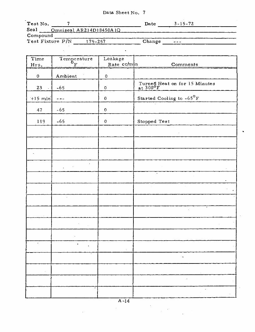
Data Sheet No. 7
Test No. 7 Date 3-15-72Seal Omniseal AR214D18450A1QCompoundTest Fixture P/N 179-257 Change ---
Time Temrnerature Leakage
Hrs. F Rate cc/m n Comments
0 Ambient 0
Turned Heat on for 15 Minutes23 -65 0 at 300 0 F
+15 min --- 0 Started Cooling to -650F
47 -65 0
119 -65 0 Stopped Test
A -14

Omniseal Test ConfigurationP/N AR214D18450AIQ
Test Fixture P/N 179-257, Chg. AConfiguration for Test 8
d ). -.
18.450 DI A.18.440
.02o0R,030
.291.281
.195 -
. 196
A-15

Data Sheet No. 8
Test No. 8 Date 4-11-72
Seal Omniseal AR 214D18450A1Q
Compound
Test Fixture P/N 179-257 Change A
Time Temgcrature Leakage
- r s. F Rate cc/rmn Comments
0 Ambient 0
1. 5 - 150F - Started to Leak
2.0 -350F 4 cc /min
2.5 -500F 7 cc/min Stopped Test
A-16
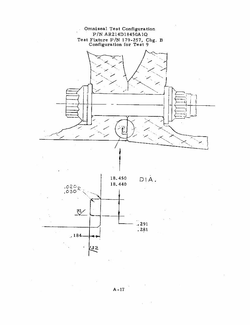
Omniseal Test ConfigurationP/N AR214D18450A1Q
Test Fixture P/N 179-257, Chg. BConfiguration for Test 9
18.450 DIA.S218.440
.- 291
.281
184---
A -17

Data Sheet No. 9
Test No. 9 Date 4-27-72
Seal Omniseal AR 214D18450A1Q
CompoundTest Fixture P/N 179-257 Change B
Time Tem erature Leakage
Hrs. -F Rate cc/m n Comments
0 Ambient 10 cc/min. Stopped Test
A-18
0(OTE 4) THREAD T-PD MUST 5E SOUARE WITH SURF. KWITHIN N FIR ACROSS 0 DCIA MI.
w_._ A PD MUST SE CONCENTRIC WITH 0 DIAWITHIN .030 FIR AND WITH D DIA
DETILA 1o 12 3
D WITHIN .005 F
S HEIGHT TOSUIT DESIGN 41* d:s*
MIN CLEARANCE € . /INVELOPE FOR FITTING :
MI DIA FOR UNRESTRICTED DETAIL A
FLOW OF FLUID MAY BE ANY
UE OR SHAPE PROVIDED NOTs MIN FLAT ROSS FACE. CLEARANCE PROVISIONSCEARANCE IS MAINTAINED TO FOR FITING. WRENCH, FITTING INSTALLATION ANDJ DEPTH FO FITTING. TOOL FILLET RADII MUST BE ADDED AS REQUIRED
--- ----- .~ .. -S .. --
*DESIGN CHART 73
Boss Dimensions For Military Straight ThreadTube Fitting O-ring Gaskets
Per MS33649 (Supersedes AND10049 and ANDI0050)
ForMS9020, MS9355, tAS28778 (AN6290), M529512 and NAS617 Gaskets
T. Trb Th.ee.d T A a C D 1 0 J NPel Advr i 0e ls Dimehn le WalI 02 P-r MO.*O47 D. M IA D I Di +.S Din MI-
0.." m.- . IT M. +.IS FU +eSs -. 000 WaSLme me.- W ID Gs - T -000
No. Dept
3-902 .064*.003 .239.003 2 .125 .3125-24UN.3 .438 .482 .062 .328 .602 .77 I
-903 .064*.003 .301*.005 3 .188 JA70-24UNJF-39 .00 .3 .125 J.390 A6 J 083
3.904 .072..003 .31*.005 4 .20 .437-20OUNJF.3 J62 .172 .44 7281
3-905 .072.003 .414.005 5 JI2 J000-20UNJF.33 .625 234 .17 .790
3-906 .078*.003 .468*005 6 .375 J625-1UNJF*3 .638 .598 .297 J.80 .083 .852 .709 004
3.907 .082.003 .330*.001 7 .438 .62501SUNJF3Si .750 .614 60 .43 .094 .915 .72
3908 .087*.003 644*.00 S .100 .700.16UNJF3S .075 .714 .391 .769 1040 .834
3.909 .097:.003 .706.005 9 J62 A.125-16UNJ-S .938 730 .438 .832 1.102 .850 r3.910 .097*..03 .75*.005 * 10 .623 8750-14UNJF-.3 1000 .802 .484 896 - 1.165 .930 .
3911 .119:.004 .863 .00S 11 .688 1.0000.12UNJP-38 1.156 . 1.023 1352
3-912 .116d.004 .924-*.006 12 .750 1.0625.12UNJ.38 1.234 .609 1.086 1.415 1.064
31.914 .1146 .004 1.047*.006 14 .074 1.111871.12UNJ-3811 1.362 .734 1.211 1.140
3,916 .116r.004 1.171*.006 14 1.000 h.3125*-2UNJ.38 1.487 .877 .844 1.36 1.665
3418 .116*.004 1 514.006 15 1.125 I--Q00.2UNJF.3 1.675 .953 1124 .125 1790 1.116
3-920 .11.00Q4 I.475*.010 20 1.250 1.250-12UNJ-3 1.8'00 171 IA411 1.978
3.924 .118.l004 IlQ010 3 1.00 I 1.8750I2UNJ-3 2.00 9 2228 1.127
3-92 .11rt.004 2.090*.o10 28 1.750 3.25002UNJ-38 2.425 1147 2.273 2,02 1.243 .010
-932 .118.*004 2.337*.0l 32 2.000 2.5000-.O UNS-31 2.67 .907 171 24 2.82 1.368
-PAKcR DASH NUMEtRS CORRESPOND WITH THOSE OF MS9020. MS935S, MS28778 AN6290), MS29512, aId NAS617.
A-19 " r
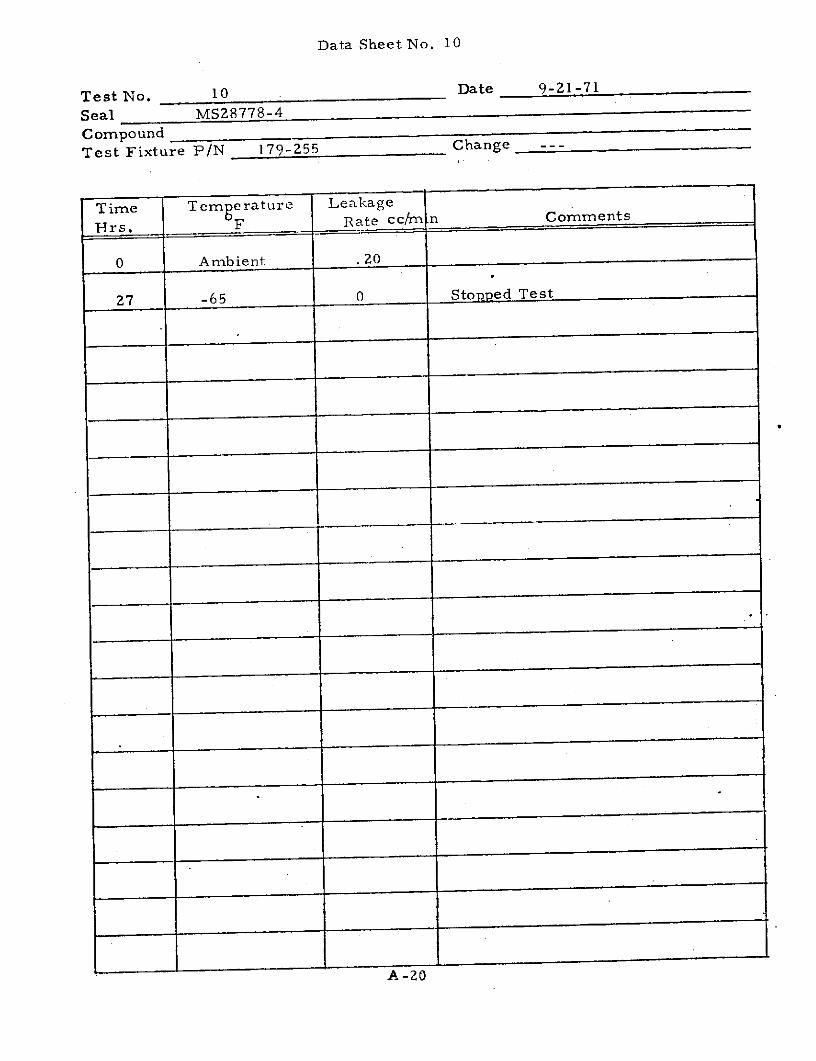
Data Sheet No. 10
Test No. 10 Date 9-21-71
Seal MS28778-4
CompoundTest Fixture P/N 179-255 Change ---
Time Temperature Leakage
Hrs. F Rate cc/mn C omments
0 Ambient .20
27 -65 0 Stopped Test
A-20

Data Sheet No. 11
Test No. 11 Date 10-7-71
Seal MS28778-4 (Repeat with New O-Ring)CompoundTest Fixture P/N 179-255 Change ---
Time Tem erature Leakage
Hrs. F Rate cc/mn M Comments
0 Ambient 0
3 -65 --- 1 cc/3 hrs.
15 -65 --- 2- cc/15 hrs.
Repea ted Test
0 Ambient ---
7 -65 --- (Opened Cold Box for 5 Minutes)
7 + 5 min -65
9 -65 --- Stopped Test
A -21

ER-4239FSC 97153
APPENDIX B
NASA ENVIRONMENTAL TESTINGOF
WHEEL AND TIRE ASSEMBLY

ER-4239FSC 97153
Introduction
Wheel seal assemblies passing the -650F temperature requirementswere assembled into two wheel and tire assemblies and tested at NASA,Houston, Texas, to the space shuttle type environmental requirements.Appendix "B" presents the wheel and tire assembly description andthe corresponding environmental test data.
Test Procedure
The wheel and tire assemblies were inflated to 312 psig and allowed toset for a period of 24 hours to allow for tire growth. The inflationpressure was readjusted to 312 psig and the environmental test wasstarted.
The pressure of the test chamber was lowered to 10 - 5 torr and itstemperature lowered to -650F. The test lasted for a period of 184 hoursfrom the time the pressure and temperature in the test chamber starteddropping until the time the tire temperature stabilized at room temper-ature at the end of the test.
Test Configuration
Wheel and Tire Assembly #1
A. Wheel Assembly B. F. Goodrich P/N 3-1342-1,except without bearing, heatshields, wheel inserts, andfuse plugs.
B. Split Wheel Air Seal Omniseal Configuration asshown on page B-3, P/NAR214D18450A1Q
C. Inflation Valve Seal MS-33649 Configuration
D. Tire C5A Tire Manufactured byB. F. Goodrich, S/N 2098AK0736
B-1

ER-4239FSC 97153
Test Configuration (Cont'd)
Wheel and Tire Assembly No. 2
A. Wheel Assembly B.F.Goodrich P/N 3-1342-1,except without bearings, heatshields, and wheel inserts.
B. Split Wheel Air Seal P/N AS666A, as shown onpage B-5 using 29. 7% O-ringsqueeze. O-ring P/N 68-185
C. Inflation Valve and Fuse Plug Seals MS-33649 Configuration
D. Tire C5A Tire Manufactured byB. F. Goodrich S/N 2098AK0190
Test Results
Wheel and Tire Assembly Nos. 1 and 2 lost 4. 0 psi and 3. 0 psi or 1.28%and 1.0% of the original tire pressure respectively during the 184 hourtest period. The allowable pressure loss was 5% of the original tirepressure. The test data is plotted on graphs on pages B-4 and B-6.
B-2

Split Wheel Air Seal ConfigurationFor Wheel and Tire Assembly No. 1
Omniseal P/N AR214D18450A 1Q
18.450 DI A.18.440
,o2 R,--
.-291;-281
. 187
. 185
B-32
B -3

-- 7 i7 4_7LNIE-SALED RE ' '
V ',4i..+M r
p'lH. '-7 :-7 :_
ET W, 4 j*+ ! , 4,! +4
.: " ,-,,T] RE PRE S R - ..--.: • . .10*... ... "0 7 7 7 7!-- .
-.- 0 . 6..0> "'1 . TiRJi.VjlRi .... m ER - HAC ER I A .... ...ER.. EM.RAT-- = .. 4 7 +4 1 *!..*I,_. .. .:" .. .m. ..r7';"3 . 1':: .- "
TIREAVERTGE=m PT E E ERATURE: "
777...71. . .:..
240.: tI: i: ----r-----: i~l~~i l1TIR PAVPA C TEPPATUREY Ti:ff~ __.
6i 22_10j1 -( 101_T_-
.. . . .:: ; : .;.:i ' ii i; -: -.Y .
.:.;lj - :,,..... =~ : it: . , r it= : .- . . .
l4 t n.
4 0 28020
L O ILI~
1]L . : '- . :::-" :." . :: ; :: :. L -cr :7 4o:1::
lir_ :7L). 4 : ."r :' .CHLP MBER TEMPERATURE ,: , ...... i, . .: ,_. .... ; :-._• , . . . . . . . . ... ." . . .. . . . . . .. " ' . .= ' ' :. . .... .. ..... . . .
- 7i 7 -7,:
:CL . 2 4 0 60 V-7:
T I -o
............. E S S E J P Fi:-_
E {i ") Ar i I-Z ;r 2.:.!:.. L :--- ;; ..L - .--:e; .-- : -:z::: " :.-: : .... '. :.:/' " " , ----,. : ...;:-: 2t-. : :,' .. .::z :_;::,. :: '=.:: ; . ;,; .-. EpE:-: ' ..: -:-;L --.r =.
4' 12,11 20 0
A' P S" E I LT.:,.. :H 0 U" R- " 5-, T ."" - . - . . . ,. . . " . . - -: .
... . : ": !- , : ." : ..... - :: :. ., .. .. . I - : - - " - 'E1_;L 5L " ' '". . . .. - . . . t - '
. . .. . .I. . . .. :&Z
! . .. .. . :-: : ... -_. .:-- ::: .,,-:. .: :, :'. : . : T 'rr , _ , E S ~ R E .. ..... .... .. .... . .. , .... : . . .. .... . ,] ::. : .
,'. ... : ". . :-, " .. ~ : ' . : :: ; . . ,.:; : -. .. . . - " .. , - t . . . , .. -2: : ;:: : : .:% :*: _ :, : : _::: :: : _ f : I : '". : :"
I-:.: :|0 20 40 60 80 0 q2 O" Oq8] 2 [
-"i " i. ... " . . . . ... . . :. .. ... ,.. . .-i- . . *: . .i : " . . " .; - " ; , T ' : ' : . .I: _ f . . . :' :- : " : : " : : :: :. . .: ,;I. .

-E .457
.440
.230
-y,.
.114r. 028
Split Wheel Air Seal Configuration For Wheel and
Tire Assembly #2.
18. 526 AS-666A Seal Configuration
29.7% O-Ring Squeeze
18.509
B-5

r I T SEALEDR TIRE
tI.1
.- ±...... . ., .. . .4. 14 47 7
2.---, 20: . 100 -.. . ... , . . . .. TIRE PR ESUR.E , :[ .,: .. .... ....
h-ti
11 9 n
I 20 1 C. 070 17 T1024 - RE- LA S I H U
. . . .... I R. . ...- --- ---- . . . . .T "7 , . - ....
4~:J 7! ...... ruti
260 6 0; 77TR 1--:F7 .-
0 '0i40016C180 2 7,
T I R -. 1 T E M"P"E. " '" .- ""R.E
"' ' " " .,. . '$. -, -- , . . . . . . .. . . . - . . . . - .. . :... ... . . . . .. . . ..i. , 4 . . .. .... _, . .. .. .. . J-... -. -- .7
7-- "' - '2 2 , 7: -1 0 T ""1•. . ... . .. . .. . . . . . ... R E.. R' E S. .S t . .. E "' " " " HL%".., I ' *_'
12 ':, .., :- .q .: ::; -- - ; '.,. . ....... . . ' ::4.... ... - .. .4 - -- . -: ... - :'::: :: -: =-77 7 : F ' = -
2 0. 0 ..-1 4,0: : " V ' : ..,: : : :' " -: - " . . .4 ; . :. .: ;-;,-,-: i ... , .., : " ....4 (J J2 0_r
" ~~O 0I 40 6..... .... . 8 ... . 1 C.. . . . . . !.. . . .,. .. "... . [ .. ... 180...'.... ... .... ... "; G: "'f:" :': :::'z. :
• I. -.. ..- - .... .. . . .. ... ... .. ... .. . . . .. ..., . ... '. .. . - ... .... ... ... ... .... :2 !: ... . .. .,....... .;r----~~ t .. . . . . - : - - L P E . .. . . .. . . . . .. . . . .. .. ,: .. . ...