Better Zsoil,Better Geotecnical Analysis · Better Zsoil,Better Geotecnical Analysis ... cement...
54
Better Zsoil,Better Geotecnical Analysis Solve complicated geotechnical problems caused by design changing of a high rise building under construction with zsoil.pc YIN JI 1,2 Email:[email protected] 1. SGIDI 2.GEOFEM
Transcript of Better Zsoil,Better Geotecnical Analysis · Better Zsoil,Better Geotecnical Analysis ... cement...

Better Zsoil,Better Geotecnical Analysis
Solve complicated geotechnical problems caused by design changing of a high rise building under construction with zsoil.pc
YIN JI 1,2 Email:[email protected]
1. SGIDI 2.GEOFEM

• Background – When the foundation slab has been constructed,
the proprietor decide to change architectural design.
– The project suspended for 6+ months.

• PART 1: Geotecnical problems encontoured

混1
先 锋 电 机 厂
规
划
道
路
混1
砼18
砼17
混1
混2
不准测量2010年10月
上 海 第 一 机 床 厂 有 限 公 司
启迪大厦 To basement sideline 37.1m
To building sideline 12.9m
Basement sideline of our project
Basement sideline of building A,3~27F Basement sideline
of building B,3~18F
Tower location (27F)
B2F, 7.0m depth
Surrounding environment of the project
2014/8/29
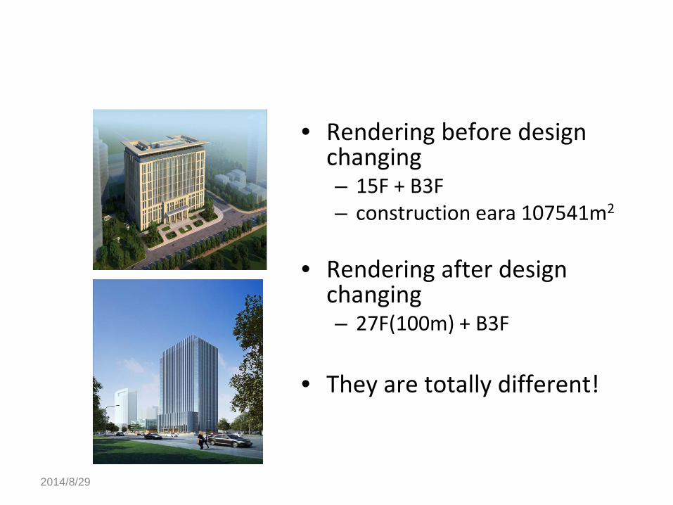
• Rendering before design changing – 15F + B3F – construction eara 107541m2
• Rendering after design
changing – 27F(100m) + B3F
• They are totally different!

2014/8/29
when the foundation slab has been constructed, the proprietor decide to change architectural design.So the project suspended for 6+ months.
reinforced concrete strut
Steel lattice column to support the strut
The current status of the project
slab, 1.2~1.8m thick

2014/8/29
building location(15F eara) before design changing
building location(27F eara) after design changing
1.2~1.8m thick slab will be removed and thickened to 2.3m. area of this
region is about 2100m2
Main building location of old and new design
Ahout 117 CIP will be added here.
35m
65m

2014/8/29
Tower pile,CIP,0.8m dia.,40m length,compressive bearing
capacity Ra=3600kN
Podium tension pile,CIP,0.6m dia.,31m length,tension bearing
capacity Ra'=1400kN
Tower pile of Building A,PHC500, 20m length,compressive bearing
capacity Ra=1400kN
Podium tension pile of Building A,PHC500, 20~24m length,tension bearing capacity Ra'=420~480kN
Pile information
Sandy silt
clay & silty clay
Sandy silt interbedded with silty clay
silt clay

2014/8/29
confined aquifier,about 6m thick, water head measured -2.0m (about 6m below the surface)
bottom of foundation pit
artesian head now Dewatering is necessary for the special geological section
Added CIP (bore hole) penetrate confied aquifier.
Artesian head must be lowered to bottom of the slab for safety
consideration.
target artesian head

cement soil mixing pile waterproof curtain
CIP,0.9m dia.,22.7m length,0.2m net spacing
Reinforced concrete strut
cement soil mixing pile soil improvment
Sectional view of retaining structure of foundation pit
3rd layer strut (partially) must be removed, otherwise there is no enough space for
piling equipment.

• current 1.2~1.8m thick slab will be removed(demolition blasting)
• 3rd strut(partially) will be removed before the contact "new" slab can sustain lateral force
• artesian head must be lowered to the bottom of the slab
• removing lateral support will cause – internal force increase of
retaining structure and strut system
– additional displacement of retaining structure and surrouding environment
• dewatering will cause – additional
displacement(settlement) of surrouding environment ,especially the builing stand on the confined aquifier (Building A).

• PART 2: Analyze geotecnical problems with ZSOIL.PC
Overall analysis and Pre-analysis
• To gain the current or initial state of internal force (stress)and displacement of foundation slab, retaining structure,strut system and building nearby, the entire construction stage should be modelled.
• Deformation+Flow is necessary to analyze displacement/settlement of surrouding environment caused by dewatering.
• To gain credible and valuable displacement information, small stiffness model, such as HS-s model is necessary.

Overall analysis and Pre-analysis
• A super structure-foundation-soil model is adopted to assess the settlement of the surrounding building acurately.
• Special attention should be paid to dewatering well simulation effectively and easily.
• According to engineering experience, pumping confined water will have an impact on the far boundary.So boundary of the model shoul be more far compared with simple Deformation analysis.

FE model
2015m
70m
1262m
building A. 3~27F excavation of
our project
refined mesh coarse mesh
mesh tying here to combine incompatible mesh

underground strutcture of builing A
shear wall column
piles
super structure-foundation-soil model
of builing A

only piles under tower are considered
trestle
retaining structure, shell hinges are used to set free rotational DOFs

piles stand on confined aquifier
strut dewatering well
retaining wall, CIP, set free DOFs
between two "piles".

how to model dewatering effectively and easily?
• model dimension should be large enough? – boundary effect is significant for some software
solving dewatering problems. – model dimension will be 2015m×1260m×70m
here.
• gradient mesh and mesh tying technology is adopted to reduce number of mesh.

how to model dewatering effectively and easily?
• dewatering wells are "glued" to the overall model with kinematic constraint. – I'd like to call it "flying well". It means you can
place it anywhere you want without remeshing the overwall model.
– "flying well" can be prepared in a seperate file, and then imported to the overall model.
– dewatering plane can be adjusted easily by changing the "flying well" file.

dewatering well type A: drainage the shallow dive.only
filter tube is modelled.
dewatering well type B: lower the artesian head to 14m below the
surface.only filter tube is modelled.
dewatering well type A: drainage the shallow dive
dewatering well type B: lower the artesian head to 14m below the surface.
foundation slab
filter tube

confined aquifier
filter tube
coarse sand
high quality clay ball
clay steel tube
dewatering well structure
only filter tube part is modelled as "flying well"

dewatering plane I:only dewatering wells(type A + type B) are modelled.
type A wells are hidden here.
inactive
inactive
inactive inactive
inactive
inactive
inactive
Drive type:Deformation + FLOW

water head for dewatering well type A
water head for dewatering well type B 3
13
12 13

Analysis stages
stage 1: initail state stage 2: 1st layer strut
stage 3: 1st layer soil stage 4: 2nd layer strut
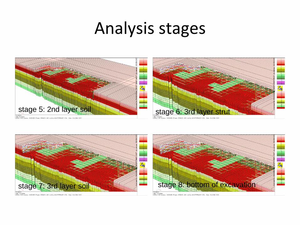
Analysis stages
stage 5: 2nd layer soil stage 6: 3rd layer strut
stage 7: 3rd layer soil stage 8: bottom of excavation

Analysis stages
stage 9: foundation slab and piles stage 10: (1)remove 3rd strut entirely; (2)remove 1.2~1.8m thick foundation slab(about 2100m2); (3) dewatering, lower the artesian head to 14m below the surface
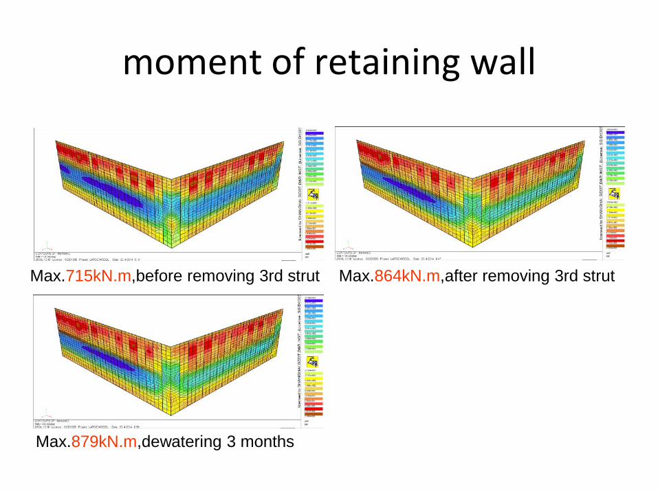
moment of retaining wall
Max.715kN.m,before removing 3rd strut Max.864kN.m,after removing 3rd strut
Max.879kN.m,dewatering 3 months

lateral displacement of retaining structure
Max.5.34cm,before removing 3rd strut Max.5.72cm,after removing 3rd strut
Max.5.76cm,dewatering 3 months
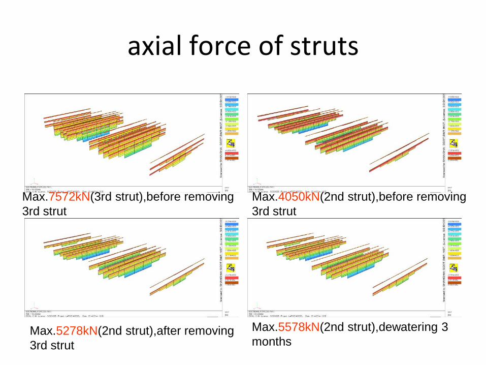
axial force of struts
Max.7572kN(3rd strut),before removing 3rd strut
Max.5278kN(2nd strut),after removing 3rd strut
Max.5578kN(2nd strut),dewatering 3 months
Max.4050kN(2nd strut),before removing 3rd strut
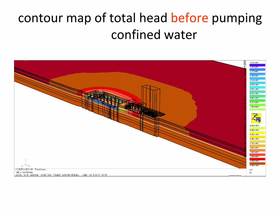
contour map of total head before pumping confined water

contour map of total head after pumping confined water

contour map of total head of confined aquifier after pumping confined water (4 month)
initial artesian head is -3.0m(about 6m below the ground surface)

contour map of add. settelment of ground sruface after pumping confined water (4 month)
Max. additional settlement 2.18cm

contour map of add. settelment of building A after pumping confined water (4 month)
Max. additional settlement 14.3mm of building A
7.71mm 6.08mm
Max. 14.3mm

recharge well type C:reduce the influence of surroundings
caused by dewatering.
dewatering plane II: dewatering wells(type A + type B + type C) are
modelled.type A wells are hidden here. Drive type: Deformation+FLOW

water head for dewatering well type A
water head for dewatering well type B
water head for recharge well type C
EXF for recharge well type C,active recharge
well time=165~300
1
3
13
12 13
165 300

contour map drawdown of confined aquifier after lowering confined water head (4 month)

contour map drawdown of confined aquifier after lowering confined water head (4 month)
recharge well type C:reduce the influence of surroundings
caused by dewatering.

contour map of add. settelment of building A after pumping confined water (4 month)
Max. additional settlement 1.91mm
7.71mm 6.08mm

• PART 3: Site construction situation
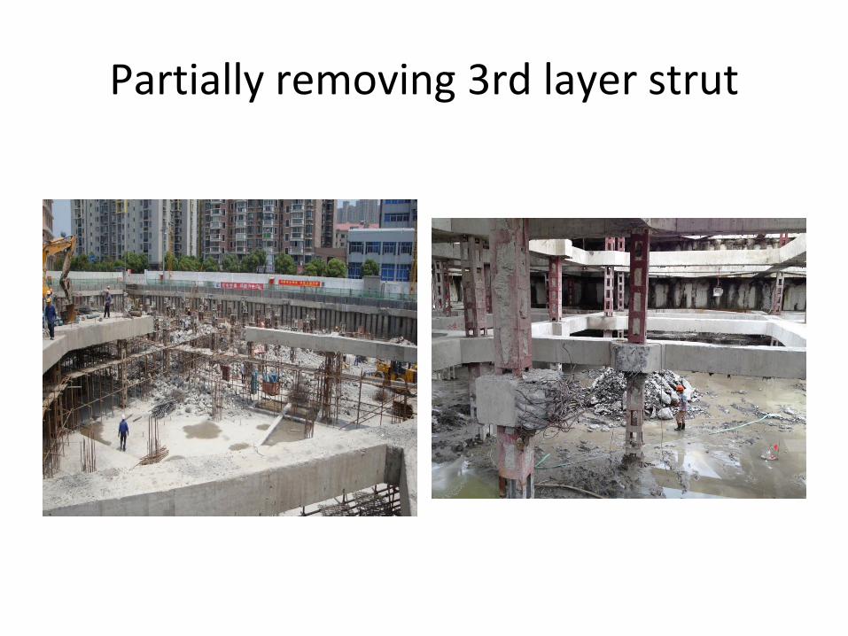
Partially removing 3rd layer strut
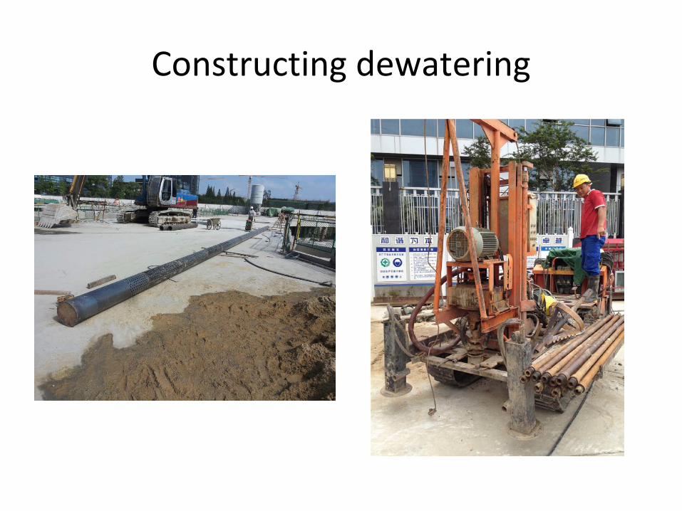
Constructing dewatering
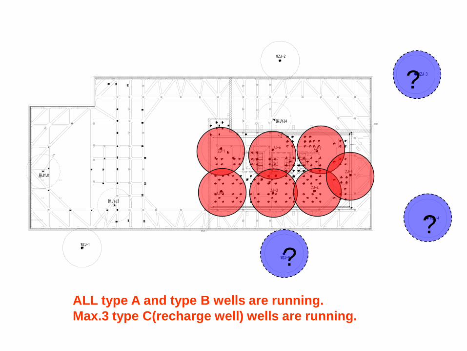
ALL type A and type B wells are running. Max.3 type C(recharge well) wells are running.
? ?
?

Removing 2100m2 foundation
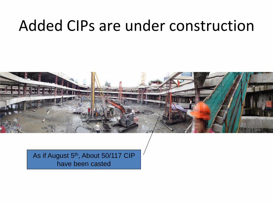
Added CIPs are under construction
As if August 5th, About 50/117 CIP have been casted

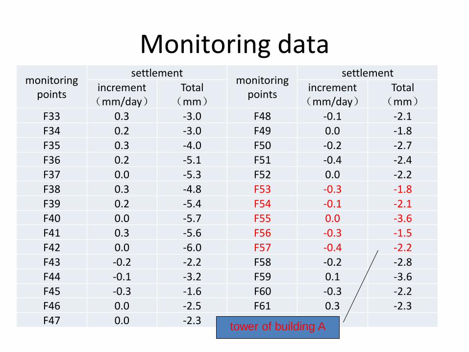
Monitoring data
• As if August 5th(continued pumping about 25 days), the max. settlement of building A caused by dewatering is about 3.6mm – including ahout 2mm caused by removing
foundation slab(demolition blasting) – no recharge well running, settlement prediction is
6.1~7.7mm – all recharge well running, settlement prediction is
0.3~0.4mm

Monitoring data 混1
主楼
混3
砼17
settlement monitoring points tower of building A
tower of building B
Monitoring data monitoring
points
settlement monitoring points
settlement increment
(mm/day) Total
(mm) increment
(mm/day) Total
(mm) F33 0.3 -3.0 F48 -0.1 -2.1 F34 0.2 -3.0 F49 0.0 -1.8 F35 0.3 -4.0 F50 -0.2 -2.7 F36 0.2 -5.1 F51 -0.4 -2.4 F37 0.0 -5.3 F52 0.0 -2.2 F38 0.3 -4.8 F53 -0.3 -1.8 F39 0.2 -5.4 F54 -0.1 -2.1 F40 0.0 -5.7 F55 0.0 -3.6 F41 0.3 -5.6 F56 -0.3 -1.5 F42 0.0 -6.0 F57 -0.4 -2.2 F43 -0.2 -2.2 F58 -0.2 -2.8 F44 -0.1 -3.2 F59 0.1 -3.6 F45 -0.3 -1.6 F60 -0.3 -2.2 F46 0.0 -2.5 F61 0.3 -2.3 F47 0.0 -2.3 tower of building A

• PART 4: Conclusion and reflection

• conclution – ZSOIL.PC can solve dewatering problems quite
well, including pumping confined water. – Recharge well can reduce the influence of
surroundings caused by dewatering significantly. – "Flying well" can simulate real dewatering well
efficiently and easily.

• reflection – Better, or at least the options available
• steel pipe pile, instead of CIP – construction without drilling – construction without dewatering
– Why not implemented • Structural engineers do not accept the same building with
different piles – vertical support stiffness of different piles(steel pipe pile vs. CIP) are
significantly different – It is hard to reconcile stiffness differences without proper tools – This problem can be solved perfectly with ZSOIL.PC, maybe next time
– Better zsoil, better geotecnical analysis and solutions

• Acknowledgement – Thank Prof. A.Truty in terms of modelling of dewatering well.