Betriebsvorschrift Operating Instructions Doppel - Öl ... Documents/AWP FT, OF, DOF, SF... e-mail:...
8
1 / 8 GEA AWP GmbH Armaturenstr. 2 17291 Prenzlau, Germany Tel.: +49 3984 8559-0 Fax: +49 3984 8559-18 www.gea.com e-mail: [email protected] DOF_58000 10.12.2014 APS 06.30 – 30.1 Double - Oil - Filter DOF – types example: vertical 580 .. 581 .. 582 .. 583 .. 584 .. Contents Page 1. Survey of Types 2 2. Technical Characteristics 3 3. Safety Instructions 4 4. Application 4 5. Functional Description 4 6. Installation 4 7. Maintenance 5 8. Transport, Storage 5 9. Warranty 6 10. Spare parts 6 11. Specification 7 12. Specification Note 8 13. Information on risks 8 Doppel - Öl - Filter DOF – Typenvertreter: stehend 580 .. 581 .. 582 .. 583 .. 584 .. Inhaltsverzeichnis Seite 1. Übersicht der Bauarten 2 2. Technische Kennwerte 3 3. Sicherheitshinweise 4 4. Anwendung 4 5. Funktionsbeschreibung 4 6. Einbau 4 7. Wartung 5 8. Transport und Lagerung 5 9. Garantie 6 10. Ersatzteile 6 11. Kennzeichnung 7 12. Kennzeichnung-Hinweis 8 13. Hinweis auf Restgefahren 8 Betriebsvorschrift Armaturen für die Kältetechnik Operating Instructions Valves for refrigeration
Transcript of Betriebsvorschrift Operating Instructions Doppel - Öl ... Documents/AWP FT, OF, DOF, SF... e-mail:...

1 / 8
GEA AWP GmbH Armaturenstr. 2
17291 Prenzlau, Germany Tel.: +49 3984 8559-0 Fax: +49 3984 8559-18
www.gea.com e-mail: [email protected]
DOF_58000 10.12.2014
APS 06.30 – 30.1
Double - Oil - Filter
DOF – types example: vertical 580 .. 581 .. 582 .. 583 .. 584 ..
Contents Page
1. Survey of Types 2
2. Technical Characteristics 3
3. Safety Instructions 4
4. Application 4
5. Functional Description 4
6. Installation 4
7. Maintenance 5
8. Transport, Storage 5
9. Warranty 6
10. Spare parts 6
11. Specification 7
12. Specification Note 8
13. Information on risks 8
Doppel - Öl - Filter
DOF – Typenvertreter: stehend 580 .. 581 .. 582 .. 583 .. 584 ..
Inhaltsverzeichnis Seite
1. Übersicht der Bauarten 2
2. Technische Kennwerte 3
3. Sicherheitshinweise 4
4. Anwendung 4
5. Funktionsbeschreibung 4
6. Einbau 4
7. Wartung 5
8. Transport und Lagerung 5
9. Garantie 6
10. Ersatzteile 6
11. Kennzeichnung 7
12. Kennzeichnung-Hinweis 8
13. Hinweis auf Restgefahren 8
Betriebsvorschrift
Armaturen für die Kältetechnik
Operating Instructions
Valves for refrigeration
2 / 8
GEA AWP GmbH Armaturenstr. 2
17291 Prenzlau, Germany Tel.: +49 3984 8559-0 Fax: +49 3984 8559-18
www.gea.com e-mail: [email protected]
DOF_58000 10.12.2014
APS 06.30 – 30.1
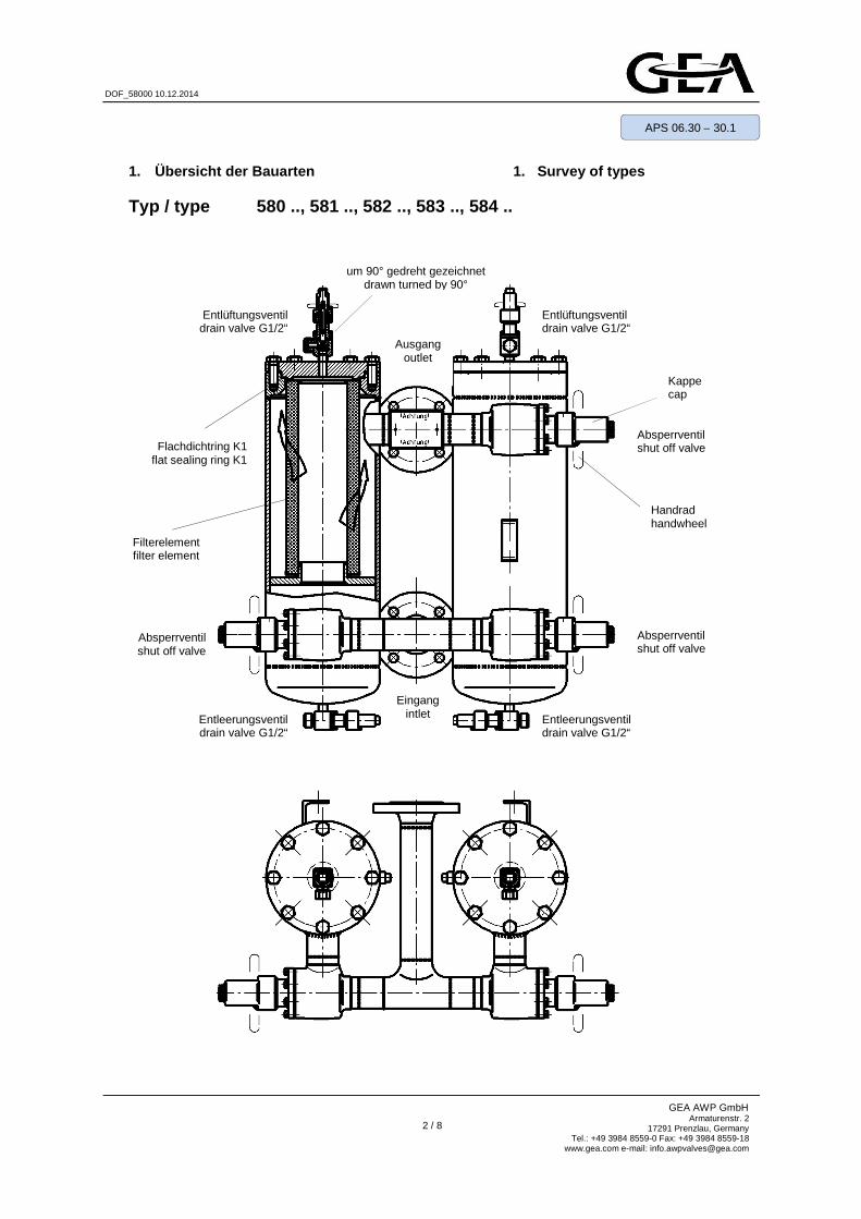
1. Übersicht der Bauarten 1. Survey of types
Typ / type 580 .., 581 .., 582 .., 583 .., 584 ..
Ausgang outlet
Handrad handwheel
Absperrventil shut off valve
Filterelement filter element
Entleerungsventil drain valve G1/2“
Kappe cap
Eingang intlet
Entlüftungsventil drain valve G1/2“
Entlüftungsventil drain valve G1/2“
Entleerungsventil drain valve G1/2“
Absperrventil shut off valve
Absperrventil shut off valve
Flachdichtring K1 flat sealing ring K1
um 90° gedreht gezeichnet drawn turned by 90°
3 / 8
GEA AWP GmbH Armaturenstr. 2
17291 Prenzlau, Germany Tel.: +49 3984 8559-0 Fax: +49 3984 8559-18
www.gea.com e-mail: [email protected]
DOF_58000 10.12.2014
APS 06.30 – 30.1
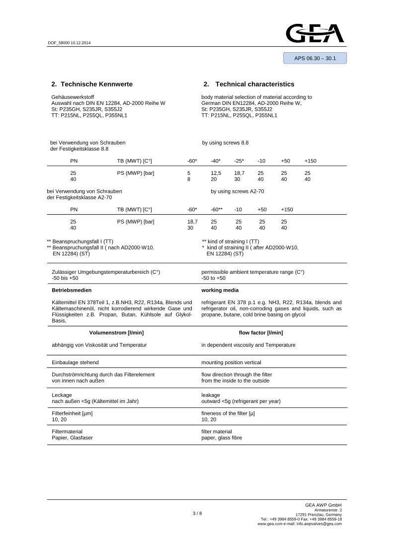
2. Technical characteristics body material selection of material according to German DIN EN12284, AD-2000 Reihe W, St: P235GH, S235JR, S355J2 TT: P215NL, P255QL, P355NL1
2. Technische Kennwerte Gehäusewerkstoff Auswahl nach DIN EN 12284, AD-2000 Reihe W St: P235GH, S235JR, S355J2 TT: P215NL, P255QL, P355NL1
permissible ambient temperature range (C°) -50 to +50 working media refrigerant EN 378 p.1 e.g. NH3, R22, R134a, blends and refrigerator oil, non-corroding gases and liquids, such as propane, butane, cold brine basing on glycol flow factor [l/min] in dependent viscosity and Temperature mounting position vertical flow direction through the filter from the inside to the outside
leakage outward <5g (refrigerant per year) fineness of the filter [µ] 10, 20 filter material paper, glass fibre
Zulässiger Umgebungstemperaturbereich (C°) -50 bis +50 Betriebsmedien Kältemittel EN 378Teil 1, z.B.NH3, R22, R134a, Blends und Kältemaschinenöl, nicht korrodierend wirkende Gase und Flüssigkeiten z.B. Propan, Butan, Kühlsole auf Glykol-Basis, Volumenstrom [l/min] abhängig von Viskosität und Temperatur Einbaulage stehend Durchströmrichtung durch das Filterelement von innen nach außen
Leckage nach außen <5g (Kältemittel im Jahr) Filterfeinheit [µm] 10, 20 Filtermaterial Papier, Glasfaser
bei Verwendung von Schrauben by using screws 8.8 der Festigkeitsklasse 8.8
PN TB (MWT) [C°] -60* -40* -25* -10 +50 +150 25 PS (MWP) [bar] 5 12,5 18,7 25 25 25 40 8 20 30 40 40 40
bei Verwendung von Schrauben by using screws A2-70 der Festigkeitsklasse A2-70
PN TB (MWT) [C°] -60* -60** -10 +50 +150 25 PS (MWP) [bar] 18,7 25 25 25 25 40 30 40 40 40 40
** Beanspruchungsfall I (TT) ** kind of straining I (TT) ** Beanspruchungsfall II ( nach AD2000-W10, * kind of straining II ( after AD2000-W10, EN 12284) (ST) EN 12284) (ST)
4 / 8
GEA AWP GmbH Armaturenstr. 2
17291 Prenzlau, Germany Tel.: +49 3984 8559-0 Fax: +49 3984 8559-18
www.gea.com e-mail: [email protected]
DOF_58000 10.12.2014
APS 06.30 – 30.1
3. Safety instructions ! Filters that have been damaged during transport or storage must not be installed. ! Filters:
- no axial forces, bending or torsion moments should act upon the filters
- must not be used as fixing points for pipes
! In the case of gas welding or brazing, the flame may not reach the filters. ! Any kind of soiling has to be kept away from the inside of the filter. ! Replace the filter element only if the filter casing is depressurized and adequately ventilated. ! For maintenance see Operating Instructions Shut-off Valves APS 06.30 – 10.1 and APS 06.30 – 10 .3 4. Application AWP-Double-Oil-Filters are suitable for being employed in the oil-cycles for industrial refrigerating plants. 5. Functional Description
AWP-Double-Oil-Filters make it possible to replace the filter elements without interrupting the service. Paper and glass fibre filters with 10 µm and 20 µm are used. The flow takes place from the inside outward. The size selection depends on the flow rate and the viscosity of the oil. AWP-valves (shut off-, ventilating-, and drain valve) are actuated by a handwheel. The valves are shut off clockwise in viewing direction towards the handwheel and are opened counter-clockwise. The valves are shut-off devices and may only be operated in "shut-off" or "open" position. When opening the valve, the stem has to be moved to the limit stop into the uppermost position (completely open). The valves are equipped with a back sealing (flat sealing ring R). !Actuateshut-offvalvesonlyinpairs! Always put only one filter into operation. 6. Installation
Before installing the oil-filter, the pipelines and the components have to be cleaned.
-please notice- The deviation from the parallelism or squareness of the welding ends or, as the case may be, the sealing surfaces of the flanges must not exceed 1°. The connecting flanges have to be coaxial. Filters that have been damaged during transport or storage must not be installed. After the protective caps have been removed, the filter scan is welded on. The flow direction (see arrow on specification label) should be observed. With modern welding processes (such as TIG, GMAW),the valves are not disassembled for welding.
-please notice- For replacing the filter elements sufficient space has to be provided on the side of the cover.
3. Sicherheitshinweise
! Filter mit Transport- oder Lagerschäden dürfen nicht eingebaut werden ! Filter:
- müssen frei von Achskräften, Biege- und Torsionsmomenten sein
- dürfen nicht als Fixpunkte von Rohrleitungen dienen
! Bei Autogenschweißung oder Hartlötung darf die Flamme den Filter nicht berühren. ! Verunreinigungen jeglicher Art müssen vom Innenraum der Filter ferngehalten werden. ! Wechsel des Filterelementes nur bei drucklosem, ausreichend belüftetem Filtergehäuse vornehmen. ! Wartung der Ventile siehe Betriebsvorschrift: Absperrventile APS 06.30 – 10.1 und APS 06.30 – 10. 3 4. Anwendung
AWP-Doppel-Öl-Filter sind geeignet für den Einsatz in Öl-Kreisläufen für Industrie-Kälteanlagen. 5. Funktionsbeschreibung
AWP-Doppel-Öl-Filter sichern den Austausch der Filterelemente ohne Betriebsunterbrechung. Es werden Filter aus Papier bzw. Glasfaser mit Filterfeinheit 10 µm bzw. 20 µm eingesetzt. Die Durchströmung erfolgt von innen nach außen. Die Größenauswahl richtet sich nach der Durchflußmenge und der Viskosität des Öles. AWP-Ventile (Absperr-, Entlüftungs- und Entleerungs-ventile) sind durch ein Handrad zu betätigen. Die Ventile werden mit Blickrichtung auf das Handrad rechts drehend geschlossen und links drehend geöffnet. Die Ventile sind Absperrarmaturen und dürfen nur in "Auf" – oder "Zu" – Stellung gefahren werden. Beim Öffnen des Ventils ist die Spindel bis zum Anschlag in die oberste Stellung zu fahren (voll geöffnet). Die Ventile sind mit einer Rückdichtung ausgerüstet (Flachdichtring R). ! Absperrventile nur – paarweise – bedienen ! Es ist immer nur ein Filter in Betrieb zu nehmen. 6. Einbau
Vor Einbau der Öl-Filter sind Rohrleitungen und Anlagen-teile zu säubern.
-bitte beachten- Die Abweichung von der Parallelität bzw. Rechtwinkligkeit der Anschweißenden bzw. Flanschdichtflächen darf 1° nicht überschreiten. Anschlußflansche müssen achsengleich sein. Filter mit Transport- und Lagerschäden dürfen nicht ein-gebaut werden. Nach dem Entfernen der Rohrstopfen können die Filter eingeschweißt bzw. montiert werden. Die Durchflußrichtung (siehe Pfeil auf Kennzeichenschild) ist einzuhalten. Bei Anwendung moderner Schweißverfahren (z.B. WIG, MAG) werden die Filter zum Einschweißen nicht demontiert.
-bitte beachten- Zum Wechsel der Filterelemente ist genügend Platz auf der Deckelseite vorzusehen.
Filter / filter 361 561 901 1401 1801 DN 20 25 32 40 50 40 50 65 65 80 80 mm 300 350 450 600 765

5 / 8
GEA AWP GmbH Armaturenstr. 2
17291 Prenzlau, Germany Tel.: +49 3984 8559-0 Fax: +49 3984 8559-18
www.gea.com e-mail: [email protected]
DOF_58000 10.12.2014
APS 06.30 – 30.1
7. Wartung AWP-Doppel-Öl-Filter arbeiten wartungsfrei. Tritt erhöhter Druckabfall über den in Betrieb befindlichen Filter auf, ist auf den in Ruhe befindlichen Filter umzuschalten. ! Absperrventile nur paarweise bedienen ! Am abgesperrten Filter ist das verschmutzte Filterelement durch ein neues zu ersetzen.
! Sicherheitshinweise beachten
• Auswechseln Filterelement
1. Filtergehäuse -drucklos- und -ölfrei- machen 2. Entlüftungs- und Entleerungsventil in
Offenstellung belassen 3. Deckelschrauben lösen, entfernen und Deckel
abnehmen.
4. Filterlelement herausnehmen und fachgerecht entsorgen. Filtergehäuse im Inneren säubern.
5. Neuen Flachdichtring K1und ein neues Filterelement entsprechend Ersatzteilübersicht in das Gehäuse einsetzen.
6. Deckel aufsetzen und mit den Schrauben gleichmäßig und über Kreuz anziehen.
7. Entlüftungs- und Entleerungsventil schließen, Deckelbereich mit Schaummitteln einpinseln und Dichtheitskontrolle durchführen.
8. Zur Inbetriebnahme Absperrventile öffnen und Filter über das Entlüftungsventil entlüften.
Wartung Absperr-, Entlüftungs- und Entleerungsventi le siehe Betriebsvorschrift APS 06.30 – 10.1 APS 06.30 – 10.3 8. Transport und Lagerung AWP-Doppel-Öl-Filter werden stoßgeschützt, mit Folie abgedeckt transportiert. Die Lagerung hat in trockenen Räumen zu erfolgen. Es ist auf den unversehrten Verschluss der Anschlussstutzen zu achten. Verschmutzungen jeglicher Art müssen vom Innenraum fern gehalten werden. Die außen liegenden Flächen der Armaturen sind mit einem Korrosionsschutzanstrich für trockene Lagerung bei Raumtemperatur versehen, der mindestens 1 Jahr wirksam ist. Der Korrosionsschutzanstrich BISPHENOL-A-Epoxidharz ist ein guter Haftvermittler für Deckanstrichstoffe auf 1- und 2- Komponenten-Basis.
7. Maintenance AWP-Double-Oil-filters are maintenance-free. In case an increased pressure drop occurs above the operating filter, switch to the non-operated filter. ! Actuate shut-off valves only in pairs ! Replace the soiled filter element of the non-operated filter by a new one.
! Follow the safety instructions • Replacing the filter element
1. Depressurize the filter casing and drain the oil. 2. Keep ventilating and drain valves in open
position. 3. Unscrew and remove the cover screws and drain
the oil.
4. Remove the filter element and ensure professional disposable. Clean the interior of the filter casing.
5. Insert a new flat sealing ring K1 and a new filter element.
6. Mount the cover and tighten the screws crosswise and evenly.
7. Close the ventilating valve and the drain valve brush the cover area with foaming agents and carry out the tightness test.
8. Open the shut-off valves and ventilate the filter by means of the ventilating valves.
Maintenance shut-off, ventilating and drain valves See Operating Instruction APS 06.30 – 10.1 APS 06.30 – 10.3 8. Transport, Storage During transport, AWP-Oil-filters are protected against shocks and covered with plastics heating. They should be stored in dry rooms. Care has to be taken that the plugs of the connecting pieces are not damaged. Any kind of soiling has to be kept away from the inside of the fitting. The external surfaces of the valves are provided with a layer of anticorrosive paint for dry storing at room temperature, which remains effective for at least 1 year. The anticorrosive paint which BISPHENOL-A-Epoxidharz is a good bonding agent for one or two-pot finishing coating paints.
DN 20 25 32 40 50 65 80 Schrauben DIN EN 24017 M12 x 30 M12 x 30 M12 x 30 M16 x 45 M16 x 45 M16 x 45 M16 x 45
screws SW 18 SW 24
DN 20 25 32 40 50 65 80 Schrauben DIN EN 24017 screws
M12 x 30
M12 x 30 SW 18
M12 x 30 M16 x 45 M16 x 45 M16 x 45 SW 24
M16 x 45
Anziehdrehmoment (8.8) Tightening moment [Nm]
85 210

6 / 8
GEA AWP GmbH Armaturenstr. 2
17291 Prenzlau, Germany Tel.: +49 3984 8559-0 Fax: +49 3984 8559-18
www.gea.com e-mail: [email protected]
DOF_58000 10.12.2014
APS 06.30 – 30.1
9. Garantie Die Garantieleistung für Erzeugnisse ist entsprechend den vertraglichen Bestimmungen im Liefervertrag festgelegt. 10. Ersatzteile Ersatzteile entsprechend Bild Seite 2: Ersatzteilbestellung: (muss enthalten)
- Anzahl - Bezeichnung entspr. Bild für Filter-Typ - Bestell-Nummer - Nennweite des Doppel-Öl-Filters - Baujahr
Bestellbeispiel:
3 Stück, Filterelement für Filtertyp 583 .., 57 50 04, DN 80, 10 / 2007
Ersatzteile Absperr-, Entlüftungs- und Entleerungsventile siehe Betriebsvorschrift APS 06.30 – 10.1 APS 06.30 – 10.3
9. Warranty The warranty services for our products have been de-fined in compliance with the regulations stipulated in the contract of delivery. 10. Spare parts Spare parts according to the illustration on page 2: Ordering spare parts: (an order must contain):
- quantity - designation according to illustration for filter type - stock number - nominal diameter of the Double-oil-filter - year of construction
Example for ordering:
3 pieces, filter element for filter type 583 .., 57 50 04, DN 80, 10 / 2007
Spare parts shut-off, ventilating and drain valves See Operating Instruction APS 06.30 – 10.1 APS 06.30 – 10.3
Typ / type Flachdichtring K1 / flat sealing ring K1
DN Bestell -Nummer stock number
Abmessung dimension
20 580 25 163 01.19.4 146 00 3 ᴓ 129 x ᴓ 115 x 1,5
32 581 40 582 50 163 01.20.4 146 00 3 ᴓ 159 x ᴓ 140 x 1,5 583 65
80
Typ / type Filterelement / filter element
DN Bestell -Nummer stock number
Abmessung dimension
20 580 25 57 50 03 101 x 60 / 230 (361)
32 581 40 57 50 09 142 x 93 / 257 (561)
50 40
582 50 57 50 02 142 x 93 / 378 (901) 65
583 65 57 50 04 142 x 93 / 505 (1401) 80
584 80 57 50 41 142 x 93 / 751 (1801)

7 / 8
GEA AWP GmbH Armaturenstr. 2
17291 Prenzlau, Germany Tel.: +49 3984 8559-0 Fax: +49 3984 8559-18
www.gea.com e-mail: [email protected]
DOF_58000 10.12.2014
APS 06.30 – 30.1
11. Specification The specification of the AWP-Oil-Filters complies with European Standard EN 12284.
- specification label of the filter casing
11. Kennzeichnung Die Kennzeichnung der AWP-Öl-Filter erfolgt entsprechend EN 12284.
- Kennzeichenschild auf dem Filtergehäuse
Rauminhalt Volume [Liter / litre]
Filtertyp / filter type DN 20 25 32 40 50 65 80
580 .. 7,3 7,3 7,3 581 .. 17,6 17,6 582 .. 20,5 20,5 20,5 583 .. 29,3 29,3 584 .. 30,5
TS (MWT) [C°] - dem Betriebsdruck zugeordnete Betriebstemperatur working temperature associated with PS (MWT) PS [bar] - maximal zulässiger Betriebsüberdruck permissible working pressure DN [mm] - Nennweite nominal diameter EN 12284 - Kältemittelarmaturen, Sicherheitstechnische Festlegungen,
Prüfung, Kennzeichnung European Standard: refirigerant valves; requirements, testing, marking
Rauminhalt [Liter] - Inhalt des Druckbehälters Volume of pressure vessel [litre]
8 / 8
GEA AWP GmbH Armaturenstr. 2
17291 Prenzlau, Germany Tel.: +49 3984 8559-0 Fax: +49 3984 8559-18
www.gea.com e-mail: [email protected]
DOF_58000 10.12.2014
APS 06.30 – 30.1
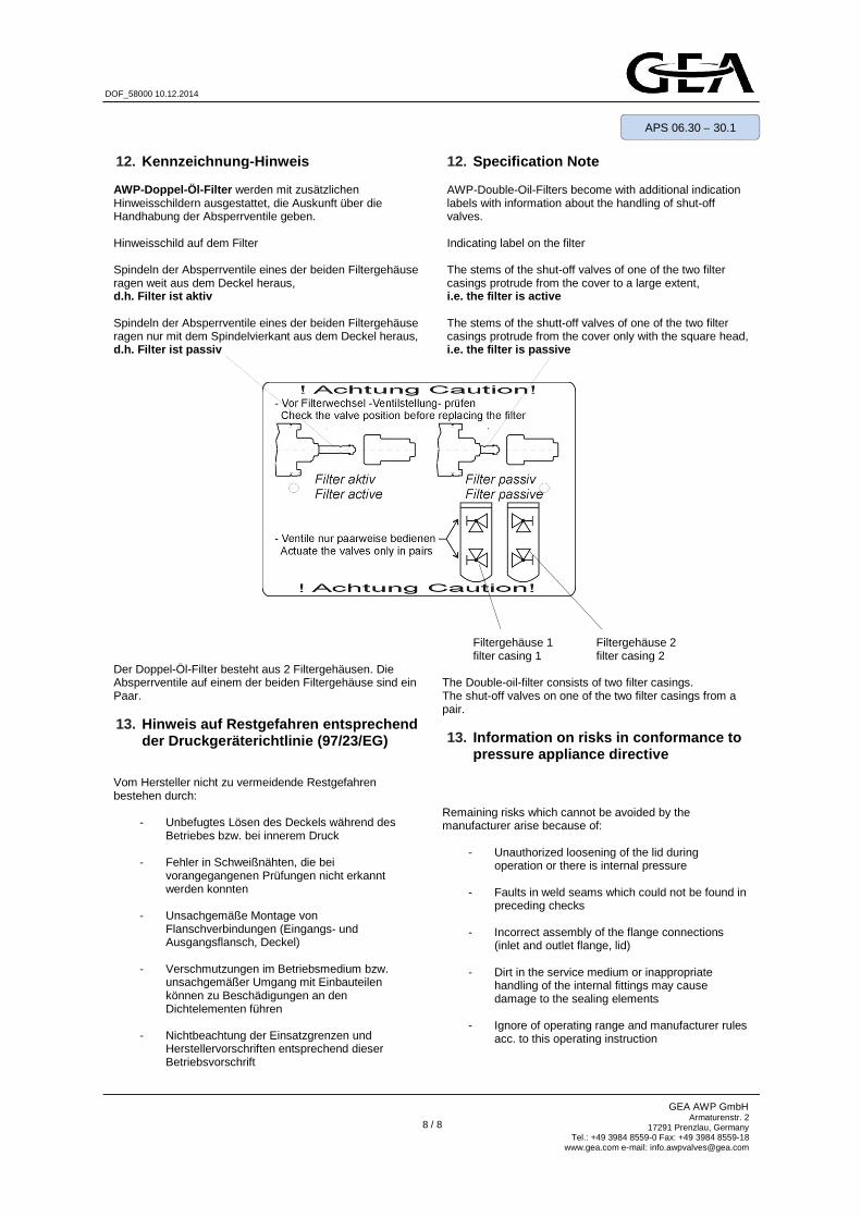
12. Kennzeichnung -Hinweis AWP-Doppel-Öl-Filter werden mit zusätzlichen Hinweisschildern ausgestattet, die Auskunft über die Handhabung der Absperrventile geben. Hinweisschild auf dem Filter Spindeln der Absperrventile eines der beiden Filtergehäuse ragen weit aus dem Deckel heraus, d.h. Filter ist aktiv Spindeln der Absperrventile eines der beiden Filtergehäuse ragen nur mit dem Spindelvierkant aus dem Deckel heraus, d.h. Filter ist passiv Der Doppel-Öl-Filter besteht aus 2 Filtergehäusen. Die Absperrventile auf einem der beiden Filtergehäuse sind ein Paar. 13. Hinweis auf Restgefahren entsprechend
der Druckgeräterichtlinie (97/23/EG) Vom Hersteller nicht zu vermeidende Restgefahren bestehen durch:
- Unbefugtes Lösen des Deckels während des Betriebes bzw. bei innerem Druck
- Fehler in Schweißnähten, die bei vorangegangenen Prüfungen nicht erkannt werden konnten
- Unsachgemäße Montage von
Flanschverbindungen (Eingangs- und Ausgangsflansch, Deckel)
- Verschmutzungen im Betriebsmedium bzw.
unsachgemäßer Umgang mit Einbauteilen können zu Beschädigungen an den Dichtelementen führen
- Nichtbeachtung der Einsatzgrenzen und
Herstellervorschriften entsprechend dieser Betriebsvorschrift
12. Specification Note AWP-Double-Oil-Filters become with additional indication labels with information about the handling of shut-off valves. Indicating label on the filter The stems of the shut-off valves of one of the two filter casings protrude from the cover to a large extent, i.e. the filter is active The stems of the shutt-off valves of one of the two filter casings protrude from the cover only with the square head, i.e. the filter is passive
Filtergehäuse 1 Filtergehäuse 2 filter casing 1 filter casing 2
The Double-oil-filter consists of two filter casings. The shut-off valves on one of the two filter casings from a pair.
13. Information on risks in conformance to
pressure appliance directive
Remaining risks which cannot be avoided by the manufacturer arise because of:
- Unauthorized loosening of the lid during operation or there is internal pressure
- Faults in weld seams which could not be found in preceding checks
- Incorrect assembly of the flange connections
(inlet and outlet flange, lid)
- Dirt in the service medium or inappropriate handling of the internal fittings may cause damage to the sealing elements
- Ignore of operating range and manufacturer rules
acc. to this operating instruction