BETE Engineering Information
8
SPECIFYING SPRAY NOZZLES Spray nozzles have three basic functions: The process of choosing a nozzle includes specifying: FLOW RATE The volume of liquid flowing through a nozzle depends primari- ly on the difference in fluid pres- sure upstream of its orifice and the pressure into which the nozzle dis- charges (normally that of the at- mosphere). Pressures that are list- ed in the flow rate tables of each nozzle series are gauge pressures. Flow rates for pressures not tab- ulated may be calculated using the equation given at the bottom of each table. The factor “K” is listed for each nozzle and has units of gpm ÷ PSI x . A nozzle may discharge into a vessel where the pressure is not atmospheric. Since the nozz le flow rate is determined by the dif- ferential pressure across it, the flow rate may be calculated by subtract- ing the gauge pressure inside the vessel from the gauge pressure at the nozzle inlet as shown: FLUID PROPERTIES Specific gravity primarily affects nozzle flow . Flow rates of liquids denser than water are lower than flow rates of water at the same pressure because more energy is required to accelerate denser flu- ids. The following relat ionship exists between flow rates of fluids with different specific gravities: Viscosity also affects nozzle per- formance. High viscosities inhibit atomization. In gen eral, fluids with viscosities greater than 100 cP are difficult to atomize except with air atomizing nozzles. SYSTEM DESIGN The piping system that supplies the nozzles must be designed to deliver the correct pressure at the Engineering Information Fluid Viscosity Specific Gravity Water 1cP SG=1 10W-30 Oil 110 cP SG=0.88 Honey 1500 cP SG=1.05 FLUID PROPERTIES (at room temperature) • meter flow • distribute liquid • break up a liquid stream into droplets a.) its flow-rate-versus-pressure characteristics (see catalog flow rate tables) b.) how the droplets will be distri- buted after leaving the nozzle (see spray pattern, pp. 2, 3) c.) the size of the droplets that will be produced (contact BETE Applications Engineering if droplet size is critical) d.) the nozzle connection to the feed pipe (see dimension tables) e.) the material of construction (see page 13 for complete list) GPM = K (PSI Inlet - PSI Vessel ) x Calculate Total Water Flow and Pressure at Pump for Nozzles Operating at 7 PSI Total Flow (pp. 38, 39) = (1 nozzle)(99 GPM/nozzle) = 99 GPM Pump Pressure Formula: P pump = P nozzle + P pipe losses + ρ h/144 Pipe Friction : (50’)(3.09 PSI/100’) = 1.6 PSI Fitting Loss : (3 elbows)(5’/elbow) = 15’ (15’)(3.09 PSI/100’) = 0.5 PSI Total Pipin g Losses: 1.6 PSI + 0.5 PSI = 2.1 PSI Elevation Losses: (62.4)(40’)/ 144 = 17.3 PSI P pump = 7 PSI + 2.1 PSI + 17.3 PSI = 26.4 PSI Pump must be sized to provide 99 GPM at 26.4 PSI Nozzle: (1) 2 1/2 ” MP1250M 2 1/2” Pipe 40’ = height www.BETE.com e e r i n g . E n g i n e e r i n g . E n g i n e e r i n g . E n g i n e e r i n g . E n g i n e e r i 110
-
Upload
erdensizgek1017 -
Category
Documents
-
view
224 -
download
0
Transcript of BETE Engineering Information

8/8/2019 BETE Engineering Information
http://slidepdf.com/reader/full/bete-engineering-information 1/8
SPECIFYING SPRAY NOZZLESSpray nozzles have three basicfunctions:
The process of choosing a nozzleincludes specifying:
FLOW RATE
The volume of liquid flowingthrough a nozzle depends primari-ly on the difference in fluid pres-sure upstream of its orifice and thepressure into which the nozzle dis-charges (normally that of the at-mosphere). Pressures that are list-ed in the flow rate tables of eachnozzle series are gauge pressures.
Flow rates for pressures not tab-ulated may be calculated using theequation given at the bottom ofeach table. The factor “K” is listedfor each nozzle and has units ofgpm ÷ PSIx.
A nozzle may discharge into avessel where the pressure is notatmospheric. Since the nozzleflow rate is determined by the dif- ferential pressure across it, the flowrate may be calculated by subtract-ing the gauge pressure inside the
vessel from the gauge pressure atthe nozzle inlet as shown:
FLUID PROPERTIES
Specific gravity primarily affectsnozzle flow. Flow rates of liquidsdenser than water are lower thanflow rates of water at the samepressure because more energy isrequired to accelerate denser flu-ids. The following relationshipexists between flow rates of fluidswith different specific gravities:
Viscosity also affects nozzle per-formance. High viscosities inhibit
atomization. In general, fluidswith viscosities greater than 100 cPare difficult to atomize except withair atomizing nozzles.
SYSTEM DESIGNThe piping system that suppliesthe nozzles must be designed todeliver the correct pressure at the
Engineering Information
Fluid Viscosity Specific Gravity
Water 1cP SG=1
10W-30 Oil 110 cP SG=0.88
Honey 1500 cP SG=1.05
FLUID PROPERTIES(at room temperature)
• meter flow
• distribute liquid• break up a liquid stream
into droplets
a.) its flow-rate-versus-pressurecharacteristics (see catalog flowrate tables)
b.) how the droplets will be distri- buted after leaving the nozzle(see spray pattern, pp. 2, 3)
c.) the size of the droplets that will be produced (contact BETEApplications Engineering ifdroplet size is critical)
d.) the nozzle connection to thefeed pipe (see dimensiontables)
e.) the material of construction (seepage 13 for complete list)
GPM = K (PSI Inlet - PSI Vessel ) x
Calculate Total Water Flow and Pressure at Pump
for Nozzles Operating at 7 PSITotal Flow (pp. 38, 39) = (1 nozzle)(99 GPM/nozzle) = 99 GPM
Pump Pressure Formula:
Ppump = Pnozzle + Ppipe losses + ρh/144
Pipe Friction: (50’)(3.09 PSI/100’) = 1.6 PSIFitting Loss: (3 elbows)(5’/elbow) = 15’
(15’)(3.09 PSI/100’) = 0.5 PSITotal Piping Losses: 1.6 PSI + 0.5 PSI = 2.1 PSIElevation Losses: (62.4)(40’)/ 144 = 17.3 PSI
Ppump = 7 PSI + 2.1 PSI + 17.3 PSI = 26.4 PSI
Pump must be sized to provide 99 GPM at 26.4 PSI
Nozzle:
(1) 2 1/2” MP1250M
2 1/2”Pipe
40’ = height
www.BETE.com e e
r i n g . E n g i n
e e r i n g . E n g
i n e e r i n g . E
n g i n e e r i n g . E n g i n e e r i
0

8/8/2019 BETE Engineering Information
http://slidepdf.com/reader/full/bete-engineering-information 2/86
Notes!PHONE: 413-772-2166 or Fax to: 413-772-6729
FLOW OF AIR THROUGH SCHEDULE 40 STEEL PIPE
Free Air Compressed
q’m ft 3
/min. Air ft3
/min. Pressure Drop per 100’ of Schedule 40 Pipe For Airat 60°F at 60°F
& 14.7 psia at 100 psig For 60° and 100 Pounds Per Square Inch (PSI)
1/8" 1/4" 3/8" 1/2"1 0.128 0.361 0.083 0.018
3/4"2 0.256 1.31 0.285 0.064 0.020
3 0.384 3.06 0.605 0.133 0.042
4 0.513 4.83 1.04 0.226 0.071
5 0.641 7.45 1.58 0.343 0.106 0.027
1" 1 1/4"6 0.769 10.6 2.23 0.408 0.148 0.037
1 1/2"8 1.025 18.6 3.89 0.848 0.255 0.062 0.019
10 1.282 28.7 5.96 1.26 0.356 0.094 0.029
15 1.922 1 3.0 2.73 0.834 0.201 0.062
20 2.563 2 2.8 4.76 1.43 0.345 0.102 0.026
25 3.204 3 5.6 7.34 2.21 0.526 0.156 0.039 0.019
30 3.845 1 0.5 3.15 0.748 0.219 0.055 0.026
35 4.486 1 4.2 4.24 1.00 0.293 0.073 0.035
40 5.126 1 8.4 5.49 1.30 0.379 0.095 0.044
2"45 5.767 2 3.1 6.90 1.62 0.474 0.116 0.055
50 6.408 2 8.5 8.49 1.99 0.578 0.149 0.067 0.019
60 7.690 4 0.7 12.2 2.85 0.819 0.200 0.094 0.027
70 8.971 1 6.5 3.83 1.10 0.270 0.126 0.036
80 10.25 0 21.4 4.96 1.43 0 .350 0.162 0.046
90 11.53 0
21/2"
.019
.023 27.0 6.25 1.80 0.437 0.203 0.058
www.BETE.com

8/8/2019 BETE Engineering Information
http://slidepdf.com/reader/full/bete-engineering-information 3/8
g g
g
g g g
g g
Water Flow DataLOW OF WATER THROUGH SCHEDULE 40 STEEL PIPE
Pressure Drop per 100 feet and Velocity in Schedule 40 Pipe for Water at 60°F
Discharge Veloc- Press. Veloc- Press. Veloc- Press. Veloc- Press. Veloc- Press. Veloc- Press. Veloc- Press. Veloc- Press.ity Drop ity Drop ity Drop ity Drop ity Drop ity Drop ity Drop ity Drop
Cubic Ft. feet Lbs. feet Lbs. feet Lbs. feet Lbs. feet Lbs. feet Lbs. feet Lbs. feet Lbs.per per per per per per per per per per per per per per per per per per
Minute Second Second Sq. In. Second Sq. In. Second Sq. In. Second Sq. In. Second Sq. In. Second Sq. In. Second Sq. In. Second Sq. In.
1/8" 1/4" 3/8" 1/2"0.2 0 .0 00 44 6 1 .13 1.86 0.616 0.359
3/4"0.3 0.000668 1.69 4.22 0.924 0.903 0.504 0.159 0.317 0.061
0.4 0.000891 2.26 6.98 1.23 1.61 0.672 0.345 0.422 0.086
0.5 0.00111 2.82 10.5 1.54 2.39 0.840 0.539 0.528 0.167 0.301 0.033
0.6 0.00178 3.39 14.7 1.85 3.29 1.01 0.751 0.633 0.240 0.361 0.041
1" 1 1/4"0.8 0.00178 4.52 25.0 2.46 5.44 1.34 1.25 0.844 0.408 0.481 0.102
1 1/2"1 0.00223 5.65 37.2 3.08 8.28 1.68 1.85 1.06 0.600 0.602 0.155 0.371 0.048
2 0.00446 11.29 134.4 6.16 30.1 3.36 6.58 2.11 2.10 1.20 0.526 0.743 0.164 0.429 0.044
3 0.00668 9.25 64.1 5.04 13.9 3.17 4.33 1.81 1.09 1.114 0.336 0.644 0.09 0.473 0.043
4 0.00891
2"12.33 111.2 6.72 23.9 4.22 7.42 2.41 1.83 1.49 0.565 0.858 0.150 0.630 0.071
5 0.01114
2 1/2"8.40 36.7 5.28 11.2 3.01 2.75 1.86 0.835 1.073 0.223 0.788 0.104
6 0.01337 0.574 0.044 10.08 51.9 6.33 15.8 3.61 3.84 2.23 1.17 1.29 0.309 0.946 0.145
8 0.01782 0.765 0.073 13.44 91.1 8.45 27.7 4.81 6.60 2.97 1.99 1.72 0.518 1.26 0.241
10 0.02228 0.956 0.108 0 .67 0 0. 046
3"10.56 42.4 6.02 9.99 3.71 2.99 2.15 0.774 1.58 0.361
15 0.03342 1.43 0.224 1.01 0.094
3 1/2"9.03 21.6 5.57 6.36 3.22 1.63 2.37 0.755
20 0.04456 1.91 0.375 1.34 0.158 0.868 0.056 12.03 37.8 7.43 10.9 4.29 2.78 3.16 1.28
25 0.05570 2.39 0.561 1.68 0.234 0.090 0.083 0.812 0.041
4"9.28 16.7 5.37 4.22 3.94 1.93
30 0.06684 2.87 0.786 2.01 0.327 1.30 0.114 0.974 0.056 11.14 23.8 6.44 5.92 4.73 2.72
35 0.07798 3.35 1.05 2.35 0.436 1.52 0.151 1.14 0.074 0.882 0.041 12.99 32.2 7.51 7.90 5.52 3.6440 0.08912 3.83 1.35 2.68 0.556 1.74 0.192 1.30 0.095 1.01 0.052 14.85 41.5 8.59 10.24 6.30 4.65
45 0.1003 4.30 1.67 3.02 0.668 1.95 0.239 1.46 0.117 1.13 0.064 9.67 12.80 7.09 5.85
50 0.1114 4.78 2.03 3.35 0.839 2.17 0.288 1.62 0.142 1.26 0.076
5"10.74 15.66 7.88 7.15
60 0.1337 5.74 2.87 4.02 1.18 2.60 0.406 1.95 0.204 1.51 0.107 12.89 22.2 9.47 10.21
70 0.1560 6.70 3.84 4.69 1.59 3.04 0.540 2.27 0.261 1.76 0.143 1.12 0.047 11.05 13.71
80 0.1782 7.65 4.97 5.36 2.03 3.47 0.687 2.60 0.334 2.02 0.180 1.28 0.060
6"12 .62 1 7.5 9
90 0.2005 8.60 6.20 6.03 2.53 3.91 0.861 2.92 0.416 2.27 0.224 1.44 0.074 14.20 22.0
100 0.2228 9.56 7.59 6.70 3.09 4.34 1.05 3.25 0.509 2.52 0.272 1.60 0.090 1.11 0.036 15.78 26.9
125 0.2785 11.97 11.76 8.38 4.71 5.43 1.61 4.06 0.769 3.15 0.415 2.01 0.135 1.39 0.055 19.72 41.4
150 0.3342 14.36 16.70 10.05 6.69 6.51 2.24 4.87 1.08 3.78 0.580 2.41 0.190 1.67 0.077
8"175 0.3899 16.75 22.3 11.73 8.97 7.60 3.00 5.68 1.44 4.41 0.774 2.81 0.253 1.94 0.102
200 0.4456 19.14 28.8 13.42 11.68 8.68 3.87 6.49 1.85 5.04 0.985 3.21 0.323 2.22 0.130
225 0.5013 - - 15.09 14.63 9.77 4.83 7.30 2.32 5.67 1.23 3.61 0.401 2.50 0.162 1.44 0.043
250 0.5570 - - - - 10.85 5.93 8.12 2.84 6.30 1.46 4.01 0.495 2.78 0.195 1.60 0.051
275 0.6127 - - - - 11.94 7.14 8.93 3.40 6.93 1.79 4.41 0.583 3.05 0.234 1.76 0.061
300 0.6684 - - - - 13.00 8.36 9.74 4.02 7.56 2.11 4.81 0.683 3.33 0.275 1.92 0.072
350 0.7798 - - - - 11.36 5.41 8.82 2.84 5.62 0.919 3.89 0.367 2.24 0.095
400 0.8912
10"- - 12.98 7.03 10.08 3.68 6.42 1.19 4.44 0.471 2.56 0.121
450 1.0030 - - 14.61 8.80 11.34 4.60 7.22 1.48 5.00 0.590 2.89 0.151
12"500 1.114 2.03 0.059 - - - - 12.60 5.65 8.02 1.81 5.55 0.720 3.21 0.182
600 1.337 2.44 0.083
14"- - 15.12 8.04 9.63 2.55 6.66 1.02 3.85 0.258
700 1.560 2.85 0.112 2.01 0.047 - - - - 11.23 3.43 7.78 1.35 4.49 0.343
800 1.782 3.25 0.143 2.29 0.061
16"- - 12.83 4.43 8.88 1.75 5.13 0.443
900 2.005 3.66 0.179 2.58 0.075 2.13 0.047 - - 14.44 5.58 9.99 2.18 5.77 0.554
1000 2.228 4.07 0.218 2.87 0.091 2.37 0.057 16.04 6.84 11.10 2.68 6.41 0.675
1200 2.674 4.88 0.306 3.44 0.128 2.85 0.080 2.18 0.042
18"- - 13.33 3.81 7.70 0.948
1400 3.119 5.70 0.409 4.01 0.171 3.32 0.107 2.54 0.055 - - 15.55 5.13 8.98 1.28
1600 3.565 6.51 0.527 4.59 0.219 3.79 0.138 2.90 0.071 - - 17.77 6.61 10.26 1.65
1800 4.010 7.32 0.663 5.16 0.276 4.27 0.172 3.27 0.088 2.58 0.050 19.99 8.37 11.54 2.08
2000 4.456 8.14 0.808 5.73 0.339 4.74 0.209 3.63 0.107 2.87 0.060 22.21 10.3 12.82 2.55
Gallons
www.BETE.com
8/8/2019 BETE Engineering Information
http://slidepdf.com/reader/full/bete-engineering-information 4/8 e e
r i n g . E n g i n
e e r i n g . E n g
i n e e r i n g . E
n g i n e e r i n g . E n g i n e e r i
Spray CoverageSPRAY ANGLE TERMSFour terms are commonly used todescribe spray coverage:
Spray Angle:
(A) The included angle of the sprayas measured close to the nozzleorifice. Since the droplets areimmediately acted upon byexternal forces (gravity andmoving gases, for example), thismeasurement is useful only fordetermining spray coverage closeto the nozzle. The spray angles lis-ted for nozzles in this catalog areangles at the nozzle, measured at
the nozzle’s design pressure, whichis highlighted in each chart of flowrate vs. pressure.Actual Spray Coverage:(B) The actual coverage at a speci-fied distance (D) from the nozzle.Effective Spray Angle:(C) The angle calculated from theactual coverage (B) at a distance (D).Theoretical Spray Coverage:(E) The coverage at distance (D) ifthe spray moved in a straight line.
EXAMPLES:Problem: To achieve a 10”diameter spray coverage from anozzle mounted 15” from thetarget, what spray angle would be required?Solution: 40° Spray Angle
Problem: How far from the targetshould a nozzle with a 110° sprayangle be mounted in order toachieve a 36” diameter spray?Solution: Approximately 15”.(Actual coverage will be less thantheoretical coverage listed inthe table.)
NOTE: For applications wherecoverage is critical, contact BETE Applications Engineering using the Application Intake Form on page 109.
4
THEORETICAL SPRAY COVERAGE (E) IN INCHES
Included Spray Distance From Nozzle Orifice (D) (inches)
Angle (A) 2 4 6 8 10 12 15 18 24 30 36
10° 0.4 0.7 1.1 1.4 1.8 2.1 2.6 3.1 4.2 5.2 6.3
20° 0.7 1.4 2.1 2.8 3.5 4.2 5.3 6.4 8.5 10.6 12.7
30° 1.1 2.1 3.2 4.3 5.4 6.4 8.1 9.7 12.8 16.1 19.3
40° 1.5 2.9 4.4 5.8 7.3 8.7 10.9 13.1 17.5 21.8 26.2
50° 1.9 3.7 5.6 7.5 9.3 11.2 14.0 16.8 22.4 28.0 33.6
60° 2.3 4.6 6.9 9.2 11.5 13.8 17.3 20.6 27.7
70° 2.8 5.6 8.4 11.2 14.0 16.8 21.0 25.2 33.6
80° 3.4 6.7 10.1 13.4 16.8 20.2 25.2 3 0.3 40.3
90° 4.0 8.0 12.0 16.0 20.0 24.0 30.0 3 6.0 48.0
100° 4.8 9.5 14.3 19.1 23.8 28.6 35.8 4 3.0
110° 5.7 11.4 17.1 22.8 28.5 34.3 42.8 5 1.4
120° 6.9 13.9 20.8 27.7 34.6 41.6 52.0 6 2.4
130° 8.6 17.2 25.7 34.3 42.9 51.5 64.4
140° 1 0. 9 2 1. 9 3 2. 9 43 .8 5 4. 8 65 .7
150°1 4. 9 2 9. 8 4 4. 7 59 .6 7 4. 5
170° 4 5. 8 9 1. 6
NOTE: Data shown is theoretical and does not take into consideration theeffects of gravity, gas flow, or high pressure operation.
www.BETE.com

8/8/2019 BETE Engineering Information
http://slidepdf.com/reader/full/bete-engineering-information 5/8
p
p
RESEARCH & DEVELOPMENTBETE’s state-of-the-art Spray Lab-oratory plays a key role in sup-porting both product R&D and ourcustomer service network.
Equipped with sophisticatedvideo-image processing and digi-tal analysis technology, the SprayLab makes possible rapid nozzledevelopment and evaluation.
The Spray Lab is also availableon a contract basis to provide con-fidential, quantitative evaluationof nozzle performance. Industrialapplications for contract testingrange from comparative nozzle
performance testing to develop-ment of proprietary designs. Thesecapabilities allow our customers tooptimize process performancewhile minimizing capital andoperating costs—a winning combi-nation in today’s competitive glo- bal marketplace.
Spray Laboratory Capabilities• Flow rate (water) measure-
ments from 0.01 to 2000 gpm
• Flow rate (air) measurementsto 3000 scfm
• Pressure measurements to10,000 psi
• Automated drop size distribu-tion measurement fromless than 2 to greater than15,000 microns
• Computerized spray distribu-tion analysis
• Two-fluid capabilities up to3000 scfm air / 2000 gpm water
• 30’. x 50’ x 22’ high test area
DROPLET ANALYSISFrustrated by the limited capabili-ties of laser-based instruments,BETE developed the Model 700Video Particle Analyzer. This flex-ible system allows BETE to char-acterize the difficult sprays con-taining significant numbers oflarge and non-spherical drops
often encountered in industrialapplications. The Model 700 is avideo-imaging system combining aCCD video camera, microscopelens, fast strobed xenon light
source, and image processinghardware and software running ona host PC-compatible computer.
PATTERN DISTRIBUTIONANALYSIS
The BETE Patternator is a uniquedigital video system for accuratelyanalyzing the volumetric distribu-tion of liquid emitted from a noz-zle. The system uses a standard
tube patternator combined withBETE's custom shape recognitionand timing software. From thisdigitized information, spray den-sity and effective spray anglesare calculated.
Because data collection and ana-lyses are handled by computer,the device is very well-suited forhandling the large amount of datarequired for nozzle developmentand assessment programs.
Consistently and accuratelyselecting appropriate samplingpositions is extremely importantwhen performing drop sizeanalysis. The challenge lies insampling the spray in such a waythat the number and locations ofthe individual tests chosen presenta reasonable representation of theentire spray. Recognizing this,BETE has integrated the patternatorwith the Model 700 analyzer on acalibrated X-Y-Z positioner anddeveloped a number of samplingprotocols for droplet size analysis.These protocols ensure that thereported drop size distributionsmost accurately reflect the overallspray performance, thus allowinga high degree of repeatabilityand confidence.
COMPUTER MODELING ANDSIMULATIONThere are instances when duplicat-ing the operating environment inthe spray lab is impossible. When
the nozzle is to be used in a high-temperature or pressure environ-ment or sprayed in a high velocitygas stream, BETE ApplicationsEngineers use computer modelingand simulation software devel-oped in-house to assist in specify-ing the proper nozzle.
Spray-modeling has also beenused to predict spray behavior inHF mitigation systems and to
specify nozzles and layouts on off-shore drilling platforms. Otherapplications include predictingspray drift from cooling ponds anddust suppression systems and esti-mating evaporation rates from dis-posal ponds.
Working with engineering com-panies and consulting groups,BETE Engineering tap this model-ing and simulation technology tooffer customized spray nozzle solu-
tions to some of the most vexingproblems facing industry today.
INDUSTRY COOPERATIVEDEVELOPMENT PROGRAMSBETE has worked closely withmajor industries in research anddevelopment programs addressingpersonnel safety and environmen-tal protection issues.
BETE has provided technicalexpertise, computer simulation,testing, and nozzle prototypes in avariety of projects, including:
• fire control aboard offshoredrilling platforms
• toxic gas control• oil spill cleanup• reducing CFC use in the semi-
conductor industry
Research & Development
www.BETE.com
8/8/2019 BETE Engineering Information
http://slidepdf.com/reader/full/bete-engineering-information 6/8
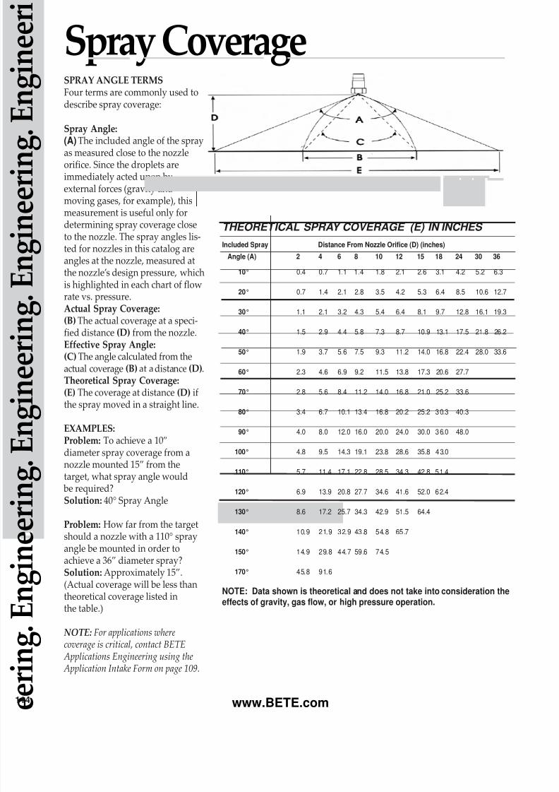
Sauter Mean Diameter (D32):• The diameter of a droplet whose
ratio of volume to surface area isequal to that of the completespray sample.
Mass (Volume) Median
Diameter (DV05):• The diameter which divides the
mass (or volume) of the spray intotwo equal halves. Thus 1/2 of thetotal mass is made up of dropletswith diameters smaller than thisnumber and the other half withdiameters that are larger.
The Sauter Mean Diameter isone of the most useful ways tocharacterize a spray. The ratio of
volume to surface area for theSauter Mean is the same as thatratio for the entire spray volume.For this reason, the use of the
Sauter Mean is preferred forprocess calculations.
Whirl nozzles generally producelarger droplets than spiral nozzles,and air-atomizing nozzles such asthe XA or SpiralAir Series typically
produce the smallest droplets of all.It is sometimes useful to predict theeffect a change in pressure will haveon the droplet size produced by thenozzle. For single fluid nozzles thefollowing equation may be used formodest changes in pressure:
TROUBLESHOOTING BASICSThe following are some of thethings to look for when a system isnot performing as intended:
Nozzle Wear or Corrosion• may cause excessive flow rate
due to enlarged passages• may increase droplet size• degrades spray pattern
Nozzle Clogging• low flow rates• poor spray pattern
Inadequate Pipe Size• excessive pipe pressure losses
leading to low nozzle pressures• high velocities in headers that
disrupt fluid entering the nozzle
Incorrect Nozzle Location• poor gas/liquid contact in
scrubbers and quenchers• poor area coverage
Incorrect Nozzle for Application• drop size too small or too large• incorrect pattern type
Careful system design and se-lection of the proper BETE nozzlewill minimize spray problems.
D 2
D 1
P 2
P 1( )-0.3=
e e
r i n g . E n g i n
e e r i n g . E n g
i n e e r i n g . E
n g i n e e r i n g . E n g i n e e r i
2
RELATIVE DROP SIZE BY NOZZLE SERIES
The BETE Droplet Analyzer is capable of characterizing non-spherical droplets like those seen in this actual image.
Actual droplet images captured using the BETE Model 700Spray Analysis System.
www.BETE.com
8/8/2019 BETE Engineering Information
http://slidepdf.com/reader/full/bete-engineering-information 7/8
nozzle inlet. The following formu-la is useful in estimating the pres-sure a pump will have to supply to
a nozzle system:
where:
ρ = density of fluid (lbs/ft 3 )
[water = 62.4 lbs/ft 3 ] h = height of nozzle above pump (ft) - negative if the
nozzle is below the pump p = pressure (PSI)
A chart of pipe friction losses is
presentedon page 115. In using thechart be sure to look at the total
system flow if there are multiplenozzles to be supplied by one pipe.Elbows, tees and other pipe fit-tings (p. 115) also contribute topressure loss and can be signifi-cant, especially in short, convolu-ted runs.
SPRAY ANGLEThe spray angle chosen for a par-
ticular application depends on thecoverage required.
The spray angle for spiral noz-zles is relatively stable over a widerange of pressures, while the sprayangle for whirl nozzles tends todecrease as the pressure is increas-ed. For additional information seepage 114.
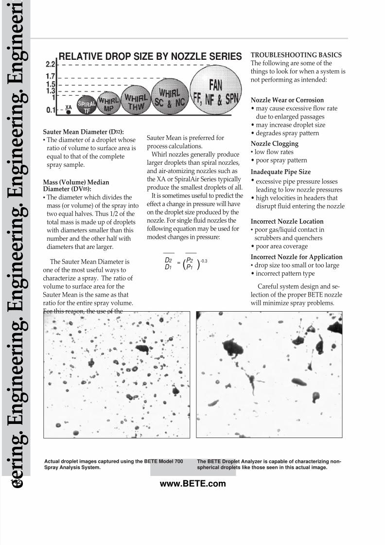
NOZZLE SPRAY PATTERNThe term “Spray Pattern”describes the location and spraydensity of the liquid emitted from
a nozzle. Two examples of pattern
measurement are shown above.The height of the curve at anypoint is the spray density in unitsof GPM/ft2.
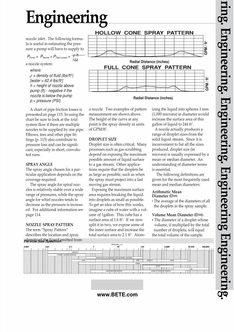
DROPLET SIZEDroplet size is often critical. Manyprocesses such as gas scrubbingdepend on exposing the maximumpossible amount of liquid surfaceto a gas stream. Other applica-tions require that the droplets be
as large as possible, such as whenthe spray must project into a fastmoving gas stream.
Exposing the maximum surfacearea requires breaking the liquidinto droplets as small as possible.To get an idea of how this works,imagine a cube of water with a vol-ume of 1gallon. This cube has asurface area of 1.6 ft2. If we nowsplit it in two, we expose some ofthe inner surface and increase thetotal surface area to 2.1 ft2. Atom-
izing the liquid into spheres 1 mm
(1,000 microns) in diameter wouldincrease the surface area of thisgallon of liquid to 244 ft2.
A nozzle actually produces arange of droplet sizes from thesolid liquid stream. Since it isinconvenient to list all the sizesproduced, droplet size (inmicrons) is usually expressed by amean or median diameter. Anunderstanding of diameter termsis essential.
The following definitions aregiven for the most frequently usedmean and median diameters:
Arithmetic MeanDiameter (D10):
• The average of the diameters of allthe droplets in the spray sample.
Volume Mean Diameter (D30):• The diameter of a droplet whose
volume, if multiplied by the totalnumber of droplets, will equal
the total volume of the sample.
Engineering
P Pump = P Nozzle + P Pipe Losses + ρ h
144 Radial Distance (inches)
G P M /
f t 2
G P M /
f t 2
Radial Distance (inches)
g g
g
g g g g
g g www.BETE.com
8/8/2019 BETE Engineering Information
http://slidepdf.com/reader/full/bete-engineering-information 8/8
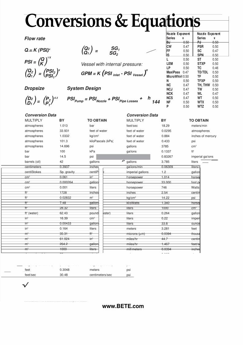
Flow rate
Q = K (PSI) x
PSI = ( Q )1/X
K
( Q 2 )Q 1 = ( PSI 2 )X
PSI 1
( Q 2 )Q 1 = √SG 1
SG 2
Vessel with internal pressure:
GPM = K ( PSI inlet - PSI Vessel ) x
Terms and Conditions.Prices quoted are FOB, Greenfield, MA. Terms are 1%/10 net 30 days for approved ac-counts.Minimum order is $50.00 net. A restocking charge of 15% will apply for standard productaccepted for return up to one year from the date of purchase. BETE FOG NOZZLE reservesthe right to charge interest on past-due accounts. No goods may be returned without priorauthorization. Non-Standard items are not subject to return.
BETE FOG NOZZLE reserves the right to make changes in specifications or design at anytime without notice. Illustrations shown in this catalog are for information only.Warranty—all goods are warranteed for good workmanship in accordance with industrystandard and will perform in accordance with the products’ specification.Limitation of Liability—BETE’s liability shall be limited to the value of the product billedarising from a purchase order.
Conversion Data
MULTIPLY BY TO OBTAINfeet/sec 18.29 meters/min
feet of water 0.0295 atmospheres
feet of water 0.884 inches of mercury
feet of water 0.433 psi
gallons 3785 cm3
gallons 0.1337 ft3
gallons 0.83267 imperial gallons
gallons 3.785 liters
gallons/min 0.06309 liters/sec
imperial gallons 1.2 gallons
horsepower 1.014 horsepower (metric)
horsepower 33.000 foot pounds/min
horsepower 746 Watts
inches 2.54 centimeters
kg/cm2 14.22 psi
kiloWatts 1.340 horsepower
liters 1000 cm3
liters 0.264 gallons
liters 0.22 imperial gallons
liters 33.8 ounces (fluid)
meters 3.281 feet
microns (µm) 0.0394 thousandth of an inch
miles/hr 44.7 centimeters/sec
miles/hr 1.467 feet/sec
millimeters 0.0394 inches
psi 0.068 atmospheres
psi 0.06895 bar
psi 2.307 feet of water
psi 0.0703 kg/cm2
psi 6.895 kPa
Conversion Data
MULTIPLY BY TO OBTAINatmospheres 1.013 bar
atmospheres 33.931 feet of water
atmospheres 1.0332 kg/cm2
atmospheres 101.3 kiloPascals (kPa)
atmospheres 14.696 psi
bar 100 kPa
bar 14.5 psi
barrels (oil) 42 gallons
centimeters 0.3937 inches
centiStokes Sp. gravity centiPoise
cm3 0.061 in3
cm3 0.000264 gallons
cm3 0.001 liters
ft3 1728 inches
ft3 0.02832 m3
ft3 7.48 gallons
ft3 28.32 liters
ft3 (water) 62.43 pounds (water)
in3 16.39 cm3
in3 0.00433 gallons
in3 0.164 liters
m3 35.31 ft3
m3 61.024 in3
m3 264.2 gallons
m3 1000 liters
degree (angle) 60 minutes
degree (Celsius) (°C x 1.8) +32 degree (Fahrenheit)
degree (Fahrenheit) (°F-32) x 0.56 degree (Celsius)
feet 0.3048 meters
feet/sec 30.48 centimeters/sec
Dropsize System Design
( D 2
D 1 ) = ( P 2 )-0.3 PSI Pump
= PSI Nozzle
+ PSI Pipe Losses
+ ρh 144 P 1
www BETE com
Nozzle Exponent Nozzle Exponent
Series x Series x
BJ 0.50 PJ 0.50
CW 0.47 PSR 0.50
FF 0.50 SC 0.47
IS 0.50 SPN 0.50
L 0.50 ST 0.50LEM 0.50 STXP 0.50
LP 0.50 TC 0.46
MaxiPass 0.47 TD/TDL 0.50
MicroWhirl 0.50 TF 0.50
N 0.50 TFXP 0.50
NC 0.47 TH, THW 0.50
NCJ 0.47 TW 0.50
NCK 0.47 WL 0.47
NCS 0.47 WT 0.50
NF 0.50 WTX 0.50
P 0.50 WTZ 0.50
Conversions & Equations