BETA Protecting Low-Voltage Fuse Systems - Siemens€¦ · BETA Protecting Low-Voltage Fuse Systems...
90
Siemens ET B1 · 10/2008 3 3 3/2 Product overview 3/4 NEOZED fuse systems 3/14 DIAZED fuse systems 3/23 3NW cylindrical fuse systems 3/28 3NW. ...-0HG Class CC fuse systems 3/30 S5T2, S5T3 busbars, for fuse systems 3/36 3NA, 3ND LV HRC fuse links 3/47 3NX1 LV HRC signal detectors 3/49 3NH LV HRC fuse bases 3/63 3NP LV HRC fuse switch disconnectors BETA Protecting Low-Voltage Fuse Systems © Siemens AG 2008 © Siemens AG 2008
Transcript of BETA Protecting Low-Voltage Fuse Systems - Siemens€¦ · BETA Protecting Low-Voltage Fuse Systems...

Siemens ET B1 · 10/2008
333/2 Product overview
3/4 NEOZED fuse systems
3/14 DIAZED fuse systems
3/23 3NW cylindrical fuse systems
3/28 3NW. ...-0HG Class CCfuse systems
3/30 S5T2, S5T3 busbars, for fuse systems
3/36 3NA, 3ND LV HRC fuse links
3/47 3NX1 LV HRC signal detectors
3/49 3NH LV HRC fuse bases
3/63 3NP LV HRC fuse switch disconnectors
BETA ProtectingLow-VoltageFuse Systems
ET_B1_2009_en.book Seite 1 Freitag, 12. Dezember 2008 9:47 09
© Siemens AG 2008© Siemens AG 2008

BETA ProtectingLow-Voltage Fuse Systems
Product overview
3/2 Siemens ET B1 · 10/2008
3
* You can order this quantity or a multiple thereof.
■ Overview
Devices Page Field of application Standards Used in
Non
-res
iden
tial
bui
ldin
gs
Res
iden
tial
bui
ldin
gs
Ind
ustr
y
NEOZED fuse systems 3/4 Fuse links, MINIZED switch disconnec-tors, bases, fuse links from 2 to 63 A of operational class gG and accessories. Everything you need for a complete system.
Fuse system:IEC 60269-3;DIN VDE 0636-3;
Safety switching devices
IEC/EN 60947-3DIN VDE 0638;DIN VDE 0660-107
✓ ✓ ✓
DIAZED fuse systems 3/14 Fuse links from 2 to 100 A in various operational classes, base versions with classic screw base connections. A widely used fuse system.
IEC 60269-3;DIN VDE 0635;DIN VDE 0636-3;CEE 16
✓ ✓ ✓
3NW cylindrical fuse systems 3/23 Line protection or protection of switching devices.
The fuse holders with touch-protection ensure the safe "no-voltage" replacement of fuse links.
Auxiliary switches can be retrofitted
IEC 60269-1, -2, -3; NF C 60-200; NF C 63-210, -211; NBN C 63269-2, CEI 32-4, -12
✓ ✓ ✓
3NW. . . .-0HG Class CC fuse systems 3/28 These comply with American standard and have UL and SCA approval, for customers exporting OEM products and mechanical engineers.
Modern design with touch protection according to BGV A3 for use in "branch circuit protection".
Fuse holders: UL 512; CSA 22.2
Fuse links: UL 248-4; CSA 22.2
✓ ✓ ✓
5ST2, 5ST3 busbars, for fuse systems
3/30 Busbars for NEOZED fuse bases, NEOZED fuse disconnectors, MINIZED switch disconnectors, DIAZED fuse systems and cylindrical fuse systems.
EN 60439-1 (VDE 0660-500)
✓ ✓ ✓
3NA, 3ND LV HRC fuse links 3/36 Fuse links from 2 to 1250 A for selective line protection and plant protection in non-residential buildings, industry and power supply companies.
IEC 60269-1, -2; EN 60269-1; DIN VDE 0636-2
✓ ✓ ✓
3NX1 LV HRC signal detectors 3/47 Signal detectors for when a fuse is tripped on all LV HRC fuse links with combination or front indicators with non-insulated grip lugs.
Plus the comprehensive accessory range required for LV HRC fuses.
✓ ✓ ✓
3NH LV HRC fuse bases 3/49 Fuse bases for screw or snap-on mounting onto standard mounting rails available as 1-pole or 3-pole version.
IEC 60269-1, -2; EN 60269-1; DIN VDE 0636-2
✓ ✓ ✓
ET_B1_2009_en.book Seite 2 Freitag, 12. Dezember 2008 9:47 09
© Siemens AG 2008© Siemens AG 2008

BETA ProtectingLow-Voltage Fuse Systems
Product overview
3/3Siemens ET B1 · 10/2008
3
* You can order this quantity or a multiple thereof.
3NP LV HRC fuse switch disconnectors
3/63 LV HRC fuse switch disconnectors for power distribution.
Versions for mounting on mounting plates, installation in front panels or on busbars.
IEC 60947-1; IEC 60947-3; VDE 0660-107
✓ -- ✓
Devices Page Field of application Standards Used in
Non
-res
iden
tial
bui
ldin
gs
Res
iden
tial
bui
ldin
gs
Ind
ustr
y
ET_B1_2009_en.book Seite 3 Freitag, 12. Dezember 2008 9:47 09
© Siemens AG 2008© Siemens AG 2008

BETA ProtectingLow-Voltage Fuse Systems
NEOZED fuse systems
3/4 Siemens ET B1 · 10/2008
3
* You can order this quantity or a multiple thereof.
■ Overview
The NEOZED fuse system is primarily used in distribution technology and industrial switchgear assemblies. The system is easy to use and is also approved for domestic installation.
MINIZED switch disconnectors are primarily used in switchgear assemblies and control engineering. They are approved for switching loads and also for safe switching in the event of short circuits. The MINIZED D02 is also suitable for use in the pre-counter area in households in accordance with the recommendations of the VDEW as defined in TAB 2007.
Due to its small footprint, the NEOZED disconnector is primarily used in control engineering.
The NEOZED fuse bases are the most cost-effective solution for the application of NEOZED fuses. All NEOZED bases must be fed from the bottom to ensure that the threaded ring is insulated during removal of the fuse link. The terminals of the NEOZED bases are available in different versions and designs to support the various installation methods.
■ Benefits
MINIZED switch disconnectors • Clear and visible conductor connection that can be easily
checked. This facilitates insertion of the conductor and saves time.
• With draw-out technology for off-circuit replacement of fuses. This provides enhanced safety.
• The infeed of the devices can be from the top or the bottom. This enables flexible application.
NEOZED fuse bases made of molded plastic• Clear and visible conductor connection that can be easily
checked. This facilitates insertion of the conductor and saves time.
• Greater safety for personnel thanks to terminals with touch-protection according to BGV A3 at incoming and outgoing feeders. This ensures enhanced safety.
• Two type ranges with different terminals offer expanded application options.
NEOZED fuse disconnectors• With draw-out technology for off-circuit replacement of fuses.
This provides enhanced safety.• Extremely slim design with a single MW per pole. This saves
space and costs.
NEOZED fuse bases made of ceramic• Different terminal versions support a huge range of different
installation methods. This ensures greater flexibility.• These bases are the most widely used devices for applications
with NEOZED fuses. An unrivaled cost-effective solution.
ET_B1_2009_en.book Seite 4 Freitag, 12. Dezember 2008 9:47 09
© Siemens AG 2008© Siemens AG 2008

BETA ProtectingLow-Voltage Fuse Systems
NEOZED fuse systems
3/5Siemens ET B1 · 10/2008
3
* You can order this quantity or a multiple thereof.
■ Technical specifications
NEOZED fuse links
5SE2
Standards IEC 60269-3; DIN VDE 0636-3
Operational class gG
Rated voltage Un V AC 400
V DC 250
Rated current In A 2 ... 100
Rated breaking capacity kA AC 50
kA DC 8
Non-interchangeability Using adapter sleeves
Resistance to climate °C Up to 45 at 95 % rel. humidity
Ambient temperature °C -5 ... +40, humidity 90 % at 20
MINIZED switch dis- connectors
MINIZED fuse switch disconnectors
Fuse bases,made of ceramic
Comfort bases
Fuse bases
D02
5SG7 1
D01
5SG7 6
D01
5SG1 5 5SG5 5
D02
5SG1 6 5SG5 6
D03
5SG1 8
D01/02
5SG1 .01 5SG5 .01
5SG1 .30 5SG1 .31 5SG5 .30
Standards DIN VDE 0638; DIN VDE 0660-107
IEC 60269-3; DIN VDE 0636-3
IEC/EN 60947-3
Main switch characteristic EN 60204-1
Yes -- --
Insulation characteristic EN 60664-1
Yes --
Rated voltage Un V AC 230/400, 240/415 400
V DC 250
• 1P V DC 65 48 --
• 2P in series V DC 130 110 --
Rated current In A 63 16 16 63 100 16/63 16/63
Rated insulation voltage V AC 500 400 --
Rated impulse withstand voltage kV AC 6 2.5 --
Overvoltage category 4 -- --
Utilization category acc. to VDE 0638
• AC-22 A 63 16 --
Utilization category acc.to EN 60947-3
• AC-22 B A 63 16 --
• AC-23 B A 35 -- --
• DC-22 B A 63 -- --
Sealable when switched on
Yes Yes, with sealable screw caps
Mounting position Any, but preferably vertical
Reduction factor of In with 18 pole
• Side-by-side mounting 0.9 --
• On top of one another, with vertical standard mounting rail
0.87 --
Degree of protection acc. to IEC 60529 IP20, with connected conductors
Terminals with touch-protection acc. to BGVA
Yes No Yes
Ambient temperature °C -5 ... +40, humidity 90 % at 20
Terminal versions -- -- B K, S K/S -- --
Conductor cross-sections
• Solid and stranded mm2 1.5 ... 35 1.5 ... 16 1.5 ... 4 1.5 ... 25 10 ... 50 0.75 ... 35 1.5 ... 35
• Flexible, with end sleeve mm2 1.5 ... 35 1.5 1.5 1.5 10 -- --
• Finely stranded, with end sleeve mm2 -- -- 0.75 ... 25 -- -- -- --
Tightening torque Nm 4 1.2 1.2 2 3.5/2.5 2.5 ... 3 3
ET_B1_2009_en.book Seite 5 Freitag, 12. Dezember 2008 9:47 09
© Siemens AG 2008© Siemens AG 2008
BETA ProtectingLow-Voltage Fuse Systems
NEOZED fuse systems
3/6 Siemens ET B1 · 10/2008* You can order this quantity or a multiple thereof.
3 ■ Selection and ordering data
Size Number of poles
In Identifi-cation color
MW DT Order No. Priceper PU
PG PU PS*/P. unit
Weightper PU approx.
A Unit(s) Unit(s) kg
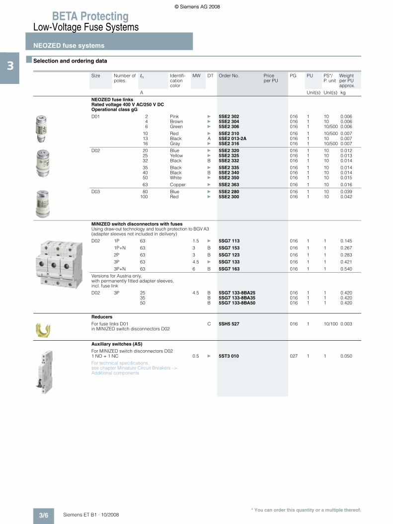
NEOZED fuse linksRated voltage 400 V AC/250 V DCOperational class gG
D01 2 Pink } 5SE2 302 016 1 10 0.0064 Brown } 5SE2 304 016 1 10 0.0066 Green } 5SE2 306 016 1 10/500 0.006
10 Red } 5SE2 310 016 1 10/500 0.00713 Black A 5SE2 013-2A 016 1 10 0.00716 Gray } 5SE2 316 016 1 10/500 0.007
D02 20 Blue } 5SE2 320 016 1 10 0.01225 Yellow } 5SE2 325 016 1 10 0.01332 Black B 5SE2 332 016 1 10 0.014
35 Black } 5SE2 335 016 1 10 0.01440 Black B 5SE2 340 016 1 10 0.01450 White } 5SE2 350 016 1 10 0.015
63 Copper } 5SE2 363 016 1 10 0.016
D03 80 Blue } 5SE2 280 016 1 10 0.039100 Red } 5SE2 300 016 1 10 0.042
MINIZED switch disconnectors with fusesUsing draw-out technology and touch protection to BGV A3(adapter sleeves not included in delivery)
D02 1P 63 1.5 } 5SG7 113 016 1 1 0.145
1P+N 63 3 B 5SG7 153 016 1 1 0.267
2P 63 3 B 5SG7 123 016 1 1 0.283
3P 63 4.5 } 5SG7 133 016 1 1 0.421
3P+N 63 6 B 5SG7 163 016 1 1 0.540
Versions for Austria only, with permanently fitted adapter sleeves, incl. fuse link
D02 3P 25 4.5 B 5SG7 133-8BA25 016 1 1 0.42035 B 5SG7 133-8BA35 016 1 1 0.42050 B 5SG7 133-8BA50 016 1 1 0.420
Reducers
For fuse links D01 in MINIZED switch disconnectors D02
C 5SH5 527 016 1 10/100 0.003
Auxiliary switches (AS)
For MINIZED switch disconnectors D021 NO + 1 NC
For technical specifications,see chapter Miniature Circuit Breakers –> Additional components
0.5 } 5ST3 010 027 1 1 0.050
ET_B1_2009_en.book Seite 6 Freitag, 12. Dezember 2008 9:47 09
© Siemens AG 2008© Siemens AG 2008

BETA ProtectingLow-Voltage Fuse Systems
NEOZED fuse systems
3/7Siemens ET B1 · 10/2008* You can order this quantity or a multiple thereof.
3
For busbars, see page 3/32 ff.1) Covers in brackets are included in the scope of supply.
Covers without brackets are not included in the scope of supply.
Size Number of poles
In Matching cover1)
MW DT Order No. Priceper PU
PG PU PS*/P. unit
Weightper PU approx.
A Unit(s) Unit(s) kg
MINIZED fuse switch disconnectorsFor industrial applications With draw-out technology and touch protection to BGV A3 (not compatible with NEOZED adapter sleeves)
D01 1P 16 1 A 5SG7 610 016 1 1 0.0701P+N 16 2 B 5SG7 650 016 1 1 0.1502P 16 2 B 5SG7 620 016 1 1 0.150
3P 16 3 A 5SG7 630 016 1 1 0.2203P+N 16 4 B 5SG7 660 016 1 1 0.300
NEOZED comfort bases made of molded plasticWith touch protection according to BGV A3
D01 1P 16 -- 1.5 } 5SG1 301 016 1 3 0.123D02 63 -- } 5SG1 701 016 1 3 0.120
D01 3P 16 -- 4.5 } 5SG5 301 016 1 1 0.371D02 63 -- } 5SG5 701 016 1 1 0.360
NEOZED fuse bases made of molded plastic With touch protection according to BGV A3
With cover
D01 1P 16 (A1) 1.5 A 5SG1 330 016 1 6 0.068D02 63 (A1) 1.5 A 5SG1 730 016 1 6 0.087
Without cover
D01 1P 16 A1 1.5 B 5SG1 331 016 1 6 0.056D02 63 A1 1.5 A 5SG1 731 016 1 6 0.080
With cover
D01 3P 16 (A2) 4.5 A 5SG5 330 016 1 2 0.216D02 63 (A2) 4.5 A 5SG5 730 016 1 2 0.252
ET_B1_2009_en.book Seite 7 Freitag, 12. Dezember 2008 9:47 09
© Siemens AG 2008© Siemens AG 2008

BETA ProtectingLow-Voltage Fuse Systems
NEOZED fuse systems
3/8 Siemens ET B1 · 10/2008* You can order this quantity or a multiple thereof.
3
1) Covers in brackets are included in the scope of supply. Covers without brackets are not included in the scope of supply.
2) For terminal versions, see page 3/13.
Size Number of poles
In Matching cover1)
Terminals2) MW DT Order No. Priceper PU
PG PU PS*/P. unit
Weightper PU approx.
A Unit(s) Unit(s) kg
NEOZED fuse bases made of ceramic
With cover
D01 1P 16 (A4) BB 1.5 } 5SG1 553 016 1 6 0.083D02 63 (A10) SS 1.5 } 5SG1 653 016 1 6 0.093D02 63 (A10) KS 1.5 } 5SG1 693 016 1 6 0.090
Without cover
D01 1P 16 A4 BB 1.5 B 5SG1 595 016 1 6 0.071D02 63 A10 SS 1.5 } 5SG1 655 016 1 6 0.081D02 63 A10 KS 1.5 B 5SG1 695 016 1 6 0.078D03 100 A6, A9 KS 2.5 A 5SG1 812 016 1 10 0.176
For screw fixing only, without cover
D01 1P 16 A4 BB 1.5 B 5SG1 590 016 1 6 0.061D02 63 A10 SS 1.5 B 5SG1 650 016 1 6 0.078D03 100 A6, A9 KS 2.5 B 5SG1 810 016 1 10 0.176
With cap
D01 1P 16 (A8) BB 1.5 } 5SG1 594 016 1 6 0.105D02 63 (A8) SS 1.5 B 5SG1 694 016 1 6 0.115D03 100 (A9) KS 2.5 B 5SG1 813 016 1 10 0.242
With cover
D01 3P 16 (A5) BB 4.5 } 5SG5 553 016 1 2 0.263D02 63 (A11) SS 4.5 } 5SG5 653 016 1 2 0.240D02 63 (A11) KS 4.5 } 5SG5 693 016 1 2 0.290
Without cover
D01 3P 16 A5 BB 4.5 B 5SG5 555 016 1 2 0.228D02 63 A11 SS 4.5 B 5SG5 655 016 1 2 0.265D02 63 A11 KS 4.5 B 5SG5 695 016 1 2 0.255
For screw fixing only, without cover
D01 3P 16 A5 BB 4.5 B 5SG5 550 016 1 2 0.228D02 63 A11 SS 4.5 B 5SG5 650 016 1 2 0.260D02 63 A11 KS 4.5 B 5SG5 690 016 1 2 0.250
NEOZED covers
Made of molded plastic, plug-in,for fuse base made of molded plastic
D01, D02
A1 1.5 C 5SH5 244 016 1 15 0.008
D01, D02
A2 4.5 C 5SH5 245 016 1 5 0.017
For fuse bases made of ceramic
D01 A4 1.5 B 5SH5 251 016 1 15 0.012D02 A10 1.5 B 5SH5 253 016 1 15 0.020
ET_B1_2009_en.book Seite 8 Freitag, 12. Dezember 2008 9:47 09
© Siemens AG 2008© Siemens AG 2008

BETA ProtectingLow-Voltage Fuse Systems
NEOZED fuse systems
3/9Siemens ET B1 · 10/2008* You can order this quantity or a multiple thereof.
3Size Matching cover
MW DT Order No. Priceper PU
PG PU PS*/P. unit
Weightper PU approx.
Unit(s) Unit(s) kg
NEOZED covers
D01 A5 4.5 C 5SH5 252 016 1 5 0.035D02 A11 4.5 C 5SH5 254 016 1 5 0.045
Screw-on
D03 A6 2.5 B 5SH5 233 016 1 20 0.021
NEOZED caps
Made of molded plastic, plug-in
D01, D02 A8 B 5SH5 235 016 1 5 0.034
Screw-on
D03 A9 C 5SH5 234 016 1 10 0.066
NEOZED screw caps
Molded plastic, with inspection hole
D01 } 5SH4 116 016 1 10/1000 0.007D02 } 5SH4 163 016 1 10/200 0.008
Ceramic
D01, sealable A 5SH4 316 016 1 10 0.014D02, sealable A 5SH4 363 016 1 10 0.015D03 A 5SH4 100 016 1 3 0.070
Ceramic, with inspection hole
D01 } 5SH4 317 016 1 20 0.014D02 } 5SH4 362 016 1 20 0.017
ET_B1_2009_en.book Seite 9 Freitag, 12. Dezember 2008 9:47 09
© Siemens AG 2008© Siemens AG 2008
BETA ProtectingLow-Voltage Fuse Systems
NEOZED fuse systems
3/10 Siemens ET B1 · 10/2008* You can order this quantity or a multiple thereof.
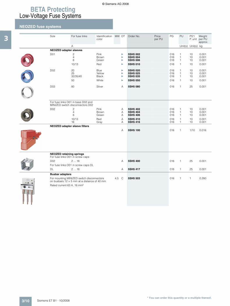
3 Size For fuse links Identification color
MW DT Order No. Priceper PU
PG PU PS*/P. unit
Weightper PU approx.
A Unit(s) Unit(s) kg
NEOZED adapter sleeves
D01 2 Pink } 5SH5 002 016 1 10 0.0014 Brown } 5SH5 004 016 1 10 0.0016 Green } 5SH5 006 016 1 10 0.001
10/13 Red } 5SH5 010 016 1 10 0.001
D02 20 Blue } 5SH5 020 016 1 10 0.00125 Yellow } 5SH5 025 016 1 10 0.00132/35/40 Black } 5SH5 035 016 1 10 0.001
50 White } 5SH5 050 016 1 10 0.001
D03 80 Silver A 5SH5 080 016 1 25 0.001
For fuse links D01 in base D02 and MINIZED switch disconnectors D02
D02 2 Pink A 5SH5 402 016 1 10 0.0014 Brown A 5SH5 404 016 1 10 0.0016 Green A 5SH5 406 016 1 10 0.001
10/13 Red A 5SH5 410 016 1 10 0.00116 Gray A 5SH5 416 016 1 10 0.001
NEOZED adapter sleeve fitters
A 5SH5 100 016 1 1/10 0.016
NEOZED retaining springsFor fuse links D01 in screw caps
D02 2 ... 16 A 5SH5 400 016 1 25 0.001
For fuse links D01 in screw caps DL
DL 2 ... 16 A 5SH5 417 016 1 25 0.001
Busbar adapters
For mounting MINIZED switch disconnectorson busbars 12 × 5 mm at a distance of 40 mm
Rated current 63 A, 16 mm²
4.5 C 5SH5 503 016 1 1 0.280
ET_B1_2009_en.book Seite 10 Freitag, 12. Dezember 2008 9:47 09
© Siemens AG 2008© Siemens AG 2008

BETA ProtectingLow-Voltage Fuse Systems
NEOZED fuse systems
3/11Siemens ET B1 · 10/2008
3
* You can order this quantity or a multiple thereof.
■ Dimensional drawings
5SG7 1.3 MINIZED switch disconnectors D02, with draw-out technology
5SG7 6 MINIZED fuse switch disconnectors D01, with draw-out technology
Fuse bases, with touch protection to BGV A3 (VBG4), molded plastic
NEOZED covers made of molded plastic
1P 1P+N 2P 3P 3P+N
1P 2P 3P 3P+N
Sizes D01/D02, with combined terminal, can be busbar mounted With cover
5SG1 301, 5SG1 701, 5SG5 301, 5SG5 701 5SG1 330, 5SG1 331, 5SG1 730, 5SG1 731, 5SG5 330, 5SG5 730
�
�
� �
�
�
�
�
� �
�
�
�
�
� �
�
�
�
�
�
�
�
�
�
�
� �
�
�
�
� �
� �
��
�
��
�������
I2_0
7988
a
18 36 54 72 6 4464
1074588
70
� � �
� ��
�
� � � �
�������
I2_0
7536
b
71,5
58,7
4526,6 79,8 4
4447,2
59,2
Protective caps
NEOZED covers for NEOZED bases, made of molded plastic
5SH5 244 (A1) and 5SH5 245 (A2)
I2_0
7537
a
71,545
26,6 79,8 16
ET_B1_2009_en.book Seite 11 Freitag, 12. Dezember 2008 9:47 09
© Siemens AG 2008© Siemens AG 2008

BETA ProtectingLow-Voltage Fuse Systems
NEOZED fuse systems
3/12 Siemens ET B1 · 10/2008
3
* You can order this quantity or a multiple thereof.
NEOZED screw caps
NEOZED fuse links
■ Schematics
5SG7 1.3 MINIZED switch disconnectors D02, with draw-out technology
5SG7 6 MINIZED fuse switch disconnectors D01, with draw-out technology
5SG1, 5SG5 NEOZED fuse switch disconnectors, made of molded plastic
NEOZED covers
5SH5 251 (A4) and 5SH5 253 (A10) 5SH5 252 (A5) and 5SH5 254 (A11) 5SH5 233 (A6)
70
27 1221
45
I2_0
6206
c
70
81 1221
45
I2_0
6209
c
13
45
45
60
I2_0
6207
c
18
5SG4 Type Size Sealable For mounting depth
Dimensions
a b
5SH4 116 D01 -- 55/70 24.5 235SH4 163 D02 -- 55/70 24.5 235SH4 316 D01 x 70 33 26.55SH4 363 D02 x 76 33 26.5
5SH4 100 D03 -- 70 37 445SH4 317 D01 -- 70 29.5 255SH4 362 D02 -- 70 30.5 25
a
I2_06253d
b
Size/thread D01/E14 D02/E18 D03/M30
Rated current in A 2 ... 16 20 ... 63 80 ... 100
Dimension d2 min 9.8 13.8 20.8
Dimension d3 11 15.3 22.5
Dimension d4 max 6 10 18
Dimension h 36 36 43
5SG7 113 5SG7 153 5SG7 123 5SG7 133 5SG7 133-8BA25 5SG7 133-8BA35 5SG7 133-8BA50
5SG7 163
1P 1P+N 2P 3P 3P+N
�
�������
�� ��
� �� � � �
1
2
1
2
N
N
1
2
3
4
1
2
3
4 6
5 1
2
3
4 6
5
N
N
5SG7 610 5SG7 650 5SG7 620 5SG7 630 5SG7 660
1P 1P+N 2P 3P 3P+N
1
2
1
2
N
N
1
2
3
4
1
2
3
4
5
6
1
2
3
4
5
6
N
N
5SG1 5SG5
1P 3P
ET_B1_2009_en.book Seite 12 Freitag, 12. Dezember 2008 9:47 09
© Siemens AG 2008© Siemens AG 2008

BETA ProtectingLow-Voltage Fuse Systems
NEOZED fuse systems
3/13Siemens ET B1 · 10/2008
3
* You can order this quantity or a multiple thereof.
■ More information
Fuse bases D01 with terminal type BB• Incoming feeders, clamp-type terminal B• Outgoing feeders, clamp-type terminal B
Fuse bases D02, with terminal type SS• Incoming feeders, saddle terminal S• Outgoing feeders, saddle terminal S
Fuse bases D02, with terminal type KS• Incoming feeders, screw head contact K• Outgoing feeders, saddle terminal S
ET_B1_2009_en.book Seite 13 Freitag, 12. Dezember 2008 9:47 09
© Siemens AG 2008© Siemens AG 2008

BETA ProtectingLow-Voltage Fuse Systems
DIAZED fuse systems
3/14 Siemens ET B1 · 10/2008
3
* You can order this quantity or a multiple thereof.
■ Overview
The DIAZED fuse system is one of the oldest fuse systems in the world. It was developed by Siemens as far back as 1906. It is still the standard fuse system in many countries to this day. It is particularly widely used in the harsh environments of industrial applications.The series is available with rated voltages from 500 to 750 V.All DIAZED bases must be fed from the bottom to ensure an insulated threaded ring when the fuse link is being removed. Reliable contact of the fuse links is only ensured when used together with DIAZED screw adapters.
The terminals of the DIAZED bases are available in different versions and designs to support the various installation methods.A key feature is the high-performing EZR bus-mounting system for screw fixing. The busbars, which are particularly suited for bus-mounting bases, have a load capacity of up to 150 A with lateral infeed.DIAZED stands for "Diametral gestuftes zweiteiliges Sicherungssystem mit Edisongewinde" (diametral two-step fuse system with Edison screw).
■ Benefits
■ Technical specifications
DIAZED fuse systems area a result of the well-designed modular system, the components can be combined in any way to meet the various requirements and to facilitate different installation methods.
$ DIAZED base
% DIAZED cover
& DIAZED cover ring
( DIAZED cap
) DIAZED fuse link, DII
* DIAZED fuse link, NDz
+ DIAZED screw adapter
, DIAZED adapter sleeve
- DIAZED screw cap
. Busbar, oblong hole, single-phase
/ Terminal, fork-type terminal, non-insulated
5SA, 5SB, 5SC, 5SD
Standards IEC 60269-3; DIN VDE 0635; DIN VDE 0636-3; CEE 16
Operational class Acc. to IEC 60269; DIN VDE 0636 gG
Characteristic Acc. to DIN VDE 0635 Slow and quick
Rated voltage Un V AC 500, 690, 750V DC 500, 600, 750
Rated current In A 2 ... 100
Rated breaking capacity kA AC 50, 40 at E16kA DC 8, 1.6 at E16
Mounting position Any, but preferably vertical
Non-interchangeability Using screw adapter or adapter sleeves
Degree of protection Acc. to IEC 60529 IP20, with connected conductors
Resistance to climate °C Up to 45, at 95 % rel. humidity
Ambient temperature °C -5 ... +40, humidity 90 % at 20
Terminal type
B K NO R
Size DII DIII NDz DII DIII DIII DIV DII DIII
Conductor cross-sections
• Rigid, min. mm2 1.5 2.5 1.0 1.5 2.5 2.5 10 1.5 1.5• Rigid, max. mm2 10 25 6 10 25 25 50 35 35• Flexible, with end sleeve mm2 10 25 6 10 25 25 50 35 35
Tightening torque
• Screw M4 Nm 1.2 --• Screw M5 Nm 2.0 --• Screw M6 Nm 2.5 4• Screw M8 Nm 3.5 --
7
9
5
3
6
811
10
2
1
4
I2_16013
ET_B1_2009_en.book Seite 14 Freitag, 12. Dezember 2008 9:47 09
© Siemens AG 2008© Siemens AG 2008

BETA ProtectingLow-Voltage Fuse Systems
DIAZED fuse systems
3/15Siemens ET B1 · 10/2008* You can order this quantity or a multiple thereof.
3■ Selection and ordering data
1) Use screw adapter 6 A.
Size Un In Identifica-tion color
Thread MW DT Order No. Priceper PU
PG PU PS*/P. unit
Weightper PU approx.
V AC/V DC
A Unit(s) Unit(s) kg
DIAZED fuse links
Operational class gG
DII 500/500 2 Pink E27 } 5SB2 11 016 1 5 0.0264 Brown } 5SB2 21 016 1 5 0.0266 Green } 5SB2 31 016 1 5 0.026
10 Red } 5SB2 51 016 1 5 0.02716 Gray } 5SB2 61 016 1 5 0.02820 Blue } 5SB2 71 016 1 5 0.02925 Yellow } 5SB2 81 016 1 5 0.031
DIII 500/500 32 Black E33 B 5SB4 010 016 1 5 0.04835 Black A 5SB4 11 016 1 5 0.05050 White A 5SB4 21 016 1 5 0.05163 Copper A 5SB4 31 016 1 5 0.054
DIV 500/400 80 Silver R1¼" B 5SC2 11 016 1 3 0.110100 Red B 5SC2 21 016 1 3 0.110
Characteristic: slow
TNDz 500/500 2 Pink E16 B 5SA2 11 016 1 10 0.0134 Brown B 5SA2 21 016 1 10 0.0136 Green B 5SA2 31 016 1 10 0.013
10 Red B 5SA2 51 016 1 10 0.01316 Gray B 5SA2 61 016 1 10 0.01320 Blue B 5SA2 71 016 1 10 0.01525 Yellow B 5SA2 81 016 1 10 0.016
Characteristic: quick
NDz 500/500 2 Pink E16 B 5SA1 11 016 1 10 0.0134 Brown B 5SA1 21 016 1 10 0.0136 Green B 5SA1 31 016 1 10 0.013
10 Red B 5SA1 51 016 1 10 0.01316 Gray B 5SA1 61 016 1 10 0.01320 Blue B 5SA1 71 016 1 10 0.01525 Yellow B 5SA1 81 016 1 10 0.016
DII 500/500 2 Pink E27 B 5SB1 11 016 1 5 0.0264 Brown B 5SB1 21 016 1 5 0.0266 Green B 5SB1 31 016 1 5 0.026
10 Red1) B 5SB1 41 016 1 5 0.026
10 Red A 5SB1 51 016 1 5 0.02716 Gray A 5SB1 61 016 1 5 0.02820 Blue A 5SB1 71 016 1 5 0.029
25 Yellow A 5SB1 81 016 1 5 0.031
DIII 500/500 35 Black E33 A 5SB3 11 016 1 5 0.05050 White A 5SB3 21 016 1 5 0.05163 Copper A 5SB3 31 016 1 5 0.054
DIV 500/500 80 Silver R1¼" B 5SC1 11 016 1 3 0.110100 Red B 5SC1 21 016 1 3 0.110
Operational class gG, use 5SF1 and 5SF5 fuse bases made of ceramic, for 2 A ... 25 A, use DII screw adapters
DIII 690/600 2 Pink E33 B 5SD8 002 016 1 5 0.0684 Brown B 5SD8 004 016 1 5 0.0686 Green B 5SD8 006 016 1 5 0.068
10 Red B 5SD8 010 016 1 5 0.06816 Gray B 5SD8 016 016 1 5 0.069
20 Blue B 5SD8 020 016 1 5 0.07125 Yellow B 5SD8 025 016 1 5 0.072
35 Black B 5SD8 035 016 1 5 0.07850 White B 5SD8 050 016 1 5 0.08063 Copper B 5SD8 063 016 1 5 0.082
ET_B1_2009_en.book Seite 15 Freitag, 12. Dezember 2008 9:47 09
© Siemens AG 2008© Siemens AG 2008

BETA ProtectingLow-Voltage Fuse Systems
DIAZED fuse systems
3/16 Siemens ET B1 · 10/2008
3
* You can order this quantity or a multiple thereof.
1) Can also be used with 690 V AC/600 V DC.
Size Un In Identifica-tion color
Thread Terminals DT Order No. Priceper PU
PG PU PS*/P. unit
Weightper PU approx.
V AC/V DC
A Unit(s) Unit(s) kg
DIAZED fuse links
Characteristic: quick, also for direct current railway facilities for 2 A ... 25 A, use DII screw adapters
DIII 750/750 2 Pink E33 A 5SD6 01 016 1 5 0.0684 Brown B 5SD6 02 016 1 5 0.0686 Green B 5SD6 03 016 1 5 0.068
10 Red B 5SD6 04 016 1 5 0.06816 Gray B 5SD6 05 016 1 5 0.069
20 Blue B 5SD6 06 016 1 5 0.07125 Yellow A 5SD6 07 016 1 5 0.07235 Black B 5SD6 08 016 1 5 0.07850 White B 5SD6 10 016 1 5 0.08063 Copper B 5SD6 11 016 1 5 0.082
DIAZED fuse bases made of ceramic
1P, for standard mounting rail
NDz 500/500 25 E16 KK A 5SF1 012 016 1 5 0.060
DII 25 E27 BB } 5SF1 005 016 1 5 0.093
DIII1) 63 E33 BS } 5SF1 205 016 1 5 0.191
DIII1) 63 E33 SS B 5SF1 215 016 1 5 0.154
1P, for screw fixing
NDz 500/500 25 E16 KK A 5SF1 01 016 1 5 0.055
DII 25 E27 BB A 5SF1 024 016 1 5 0.093
DIII1) 63 E33 BS A 5SF1 224 016 1 5 0.137
DIII1) 63 E33 SS B 5SF1 214 016 1 5 0.141
1P, with flat terminal
DIV 100 R1¼" B 5SF1 401 016 1 1 0.380
3P, for standard mounting rail, with cap and N-type fixpoint terminal
DII 500/500 3 × 25 E27 BB B 5SF5 067 016 1 1 0.400
DIII1) 3 × 63 E33 BB B 5SF5 237 016 1 1 0.580
3P, for screw fixing, with cap and N-type fixpoint terminal
DII 500/500 3 × 25 E27 KB B 5SF5 066 016 1 1 0.410
DIII1) 3 × 63 E33 KB B 5SF5 236 016 1 1 0.590
DIAZED fuse bases made of molded plasticWith touch protection BGV A3
1P, for standard mounting rail or screw fixing
DII 500/500 25 E27 } 5SF1 060 016 1 3/108 0.152
DIII1) 63 E33 } 5SF1 260 016 1 3/108 0.186
3P
DII 500/500 3 × 25 E27 } 5SF5 068 016 1 1/36 0.457
DIII1) 3 × 63 E33 } 5SF5 268 016 1 1/36 0.538
ET_B1_2009_en.book Seite 16 Freitag, 12. Dezember 2008 9:47 09
© Siemens AG 2008© Siemens AG 2008

BETA ProtectingLow-Voltage Fuse Systems
DIAZED fuse systems
3/17Siemens ET B1 · 10/2008
3
* You can order this quantity or a multiple thereof.
1) Can also be used with 690 V AC/600 V DC.
Size Un In Thread Terminals DT Order No. Priceper PU
PG PU PS*/P. unit
Weightper PU approx.
V AC/V DC A Unit(s) Unit(s) kg
DIAZED components 750 V
DIAZED fuse bases 1P, for screw fixing,with fine thread and cap
DIII 750/750 63 E33S KK A 5SF4 230 016 1 1 0.460
DIAZED screw caps made of ceramic, with fine thread
DIII 750/750 63 E33S A 5SH1 161 016 1 5 0.084
DIAZED EZR bus-mounting bases
1P, to snap onto EZR busbarsfor screw fixing
DII 500/500 25 E27 B B 5SF6 005 016 1 5 0.072
DIII 500/500 63 E33 B B 5SF6 205 016 1 5 0.135
DIAZED screw caps
Ceramic
NDz 500/500 25 E16 A 5SH1 11 016 1 5/200 0.016
Molded plastic, with inspection hole, black,not for SILIZED fuse links
DII 500/500 25 E27 } 5SH1 221 016 1 5/200 0.026
DIII1) 63 E33 } 5SH1 231 016 1 5/5000 0.042
Ceramic
DII 500/500 25 E27 } 5SH1 12 016 1 30 0.034
DIII1) 63 E33 } 5SH1 13 016 1 30 0.059
Ceramic, with inspection hole, sealable
DII 500/500 25 E27 A 5SH1 22 016 1 30 0.050
DIII1) 63 E33 A 5SH1 23 016 1 30 0.076
Ceramic
DIV 500/500 100 R1¼" C 5SH1 141 016 1 1 0.181
Ceramic, prolonged version
DIII 690/600 63 E33 A 5SH1 170 016 1 5 0.086
ET_B1_2009_en.book Seite 17 Freitag, 12. Dezember 2008 9:47 09
© Siemens AG 2008© Siemens AG 2008

BETA ProtectingLow-Voltage Fuse Systems
DIAZED fuse systems
3/18 Siemens ET B1 · 10/2008
3
* You can order this quantity or a multiple thereof.
Size Thread For fuse links
DT Order No. Priceper PU
PG PU PS*/P. unit
Weightper PU approx.
A Unit(s) Unit(s) kg
DIAZED screw adapters
NDz E16 2 C 5SH3 28 016 1 10 0.0024 C 5SH3 31 016 1 10 0.0026 C 5SH3 05 016 1 10 0.002
10 C 5SH3 06 016 1 10 0.00216 C 5SH3 07 016 1 10 0.002
Also for 5SF2 30 up to 750 V
DII E27 2 } 5SH3 10 016 1 25 0.0154 } 5SH3 11 016 1 25 0.0156 } 5SH3 12 016 1 25 0.015
10 } 5SH3 13 016 1 25 0.01516 } 5SH3 14 016 1 25 0.01420 } 5SH3 15 016 1 25 0.012
25 } 5SH3 16 016 1 25 0.012
Also for 5SF2 30 up to 750 V
DIII E33 35 } 5SH3 17 016 1 25 0.01950 } 5SH3 18 016 1 25 0.01863 } 5SH3 20 016 1 25 0.017
DIAZED adapter sleeves
DIV R1¼" 80 C 5SH3 21 016 1 10/1000 0.006100 C 5SH3 22 016 1 10/1000 0.005
DIAZED adapter sleeves for screw caps
For NDz/TNDz fuse links in base DII C 5SH3 01 016 1 10 0.012
For DII fuse links in base DIII B 5SH3 02 016 1 10 0.023
DIAZED adapter sleeve fitters
DII/DIII A 5SH3 703 016 1 1 0.025
DIAZED covers made of molded plastic
Not for SILIZED fuse links
DII 5 bases = 12 MW E27 } 5SH2 032 016 1 10/620 0.017DIII 4 bases = 12 MW E33 } 5SH2 232 016 1 10/620 0.020
DIAZED caps made of molded plastic
NDz E16 A 5SH2 01 016 1 5 0.028DII E27 A 5SH2 02 016 1 5 0.038DIII E33 A 5SH2 22 016 1 5 0.048
ET_B1_2009_en.book Seite 18 Freitag, 12. Dezember 2008 9:47 09
© Siemens AG 2008© Siemens AG 2008

BETA ProtectingLow-Voltage Fuse Systems
DIAZED fuse systems
3/19Siemens ET B1 · 10/2008
3
* You can order this quantity or a multiple thereof.
■ Dimensional drawings
DIAZED fuse links
Size Thread DT Order No. Priceper PU
PG PU PS*/P. unit
Weightper PU approx.
Unit(s) Unit(s) kg
DIAZED cover rings
Ceramic DII and DIII, also for EZR bus-mounting base
NDz E16 C 5SH3 30 016 1 5 0.020DII E27 B 5SH3 32 016 1 10 0.029DIII E33 B 5SH3 34 016 1 10 0.035
Made of molded plastic, also for EZR bus-mounting base
DII E27 A 5SH3 401 016 1 5/60 0.013DIII E33 A 5SH3 411 016 1 5/60 0.014
5SA1, 5SA2 Size/thread TNDz/E16, NDz/E16
Rated current in A 2 4 6 10 16 20 25
Dimension d 6 6 6 8 10 12 14
49
I2_06251b
Ø13
,2
Ød
5SB1, 5SB2 Size/thread DII/E27
Rated current in A 2 4 6 10 16 20 25
Dimension d 6 6 6 8 10 12 14I2_06247b
Ød
49
Ø22
,5
5SB3, 5SB4 Size/thread DIII/E33
Rated current in A 32 35 50 63
Dimension d 16 16 18 20
49
I2_06248b
Ød
Ø28
5SC1, 5SC2 Size/thread DIV/R1¼"
Rated current in A 80 100
Dimension d 5 7
Ø34
,5
Ød
I2_06682a
57
5SD6, 5SD8 Size/thread DIII/E33
Rated current in A 2 4 6 10 16 20 25 35 50 63
Dimension d 6 6 6 8 10 12 14 16 18 20
70
I2_06329b
Ød
Ø28
ET_B1_2009_en.book Seite 19 Freitag, 12. Dezember 2008 9:47 09
© Siemens AG 2008© Siemens AG 2008

BETA ProtectingLow-Voltage Fuse Systems
DIAZED fuse systems
3/20 Siemens ET B1 · 10/2008
3
* You can order this quantity or a multiple thereof.
DIAZED fuse bases made of ceramic
DIAZED fuse bases made of molded plastic
5SF1 Version Terminal type
Dimensions
Type a b c d e ∅g h ∅i
NDz/25 A5SF1 012 KK 29 49 44.6 55 75 32 49 --5SF1 01 KK 29 49 44.6 55 75 32 49 4.2
DII/25 A5SF1 005 BB 38.4 41 46.6 53 83 34 63 --5SF1 024 BB 38.4 41 46.6 53 83 34 63 4.3
DIII/63 A5SF1 205 BS 45.5 46 47 54 83 43 78 --5SF1 215 SS 45.5 46 47 54 83 43 78 --5SF1 224 BS 45.5 46 47 54 83 43 78 4.35SF1 214 SS 45.5 46 47 54 83 43 78 4.3
DIV/100 A5SF1 401 Flat
connection68 68 -- 79 110 65 116 6.5
I2_0
6242
ba
bh
Øi
cg
d
e
5SF4 230
80max.113
12
5105
5065
M6
I2_0
6443
a
5SF5 Version Terminal type
DimensionsType a b c d e f g h
DII/3 × 25 A5SF5 067 BB 106 106 48 -- -- 45 52 865SF5 066 KB 106 106 48 32 5.2 45 52 86
DIII/3 × 63 A5SF5 237 BB 127 130 54 -- -- 45 52 855SF5 236 KB 127 130 54 32 5.2 45 52 85
I2_0
8035
a
a
cb
fh
g
d
e
5SF15SF5 Type Dimensionsa b
5SF1 060 40 --5SF1 260 50 --
5SF5 068 -- 1205SF5 268 -- 150
���
������
����
� �
ET_B1_2009_en.book Seite 20 Freitag, 12. Dezember 2008 9:47 09
© Siemens AG 2008© Siemens AG 2008

BETA ProtectingLow-Voltage Fuse Systems
DIAZED fuse systems
3/21Siemens ET B1 · 10/2008
3
* You can order this quantity or a multiple thereof.
DIAZED EZR bus-mounting bases
DIAZED screw caps/cover rings made of molded plastic/ceramic
DIAZED covers made of molded plastic
DIAZED caps made of molded plastic
5SF6 005, 5SF6 205
Screw caps Cover rings Screw caps Cover rings
5SH1 5SH3 Size/thread Type Dimensions Type Dimensionsa ∅b a ∅b
NDz/E16 5SH1 11 35 28 5SH3 30 16.5 30
DII/E27 5SH1 221 42 33 5SH3 401 17.5 39.55SH1 12 45.5 34 5SH3 32 17.5 41.55SH1 22 43 39
DIII/E33 5SH1 231 42 40 5SH3 411 17.5 49.55SH1 13 45.5 43 5SH3 34 19 51.55SH1 23 47 45
5SH1 161 48 485SH1 170 68 43
DIV/R1¼" 5SH1 141 53 65
41,5 45
18
1114
max.8331
16
27max.38,5
30
20,5
31
5
I2_0
6444
a
34max.49
3722
5,3
34 51,5
55
18
1114
max.8331I2
_064
45a
16
a
I2_06253d
b
I2_13741
b
a
5SH2 Size/thread Type Dimensionsa b ∅c d
DII/E27 5SH2 032 41 51 27.5 19
DIII/E33 5SH2 232 52 51 34.5 18.5
d
I2_06255c
c
a
b
5SH2 Size/thread Type Dimensionsamax bmax cmax dmax
NDz/E16 5SH2 01 33 68 51.7 75
DII/E27 5SH2 02 43 74.7 53.6 83
DIII/E33 5SH2 22 51 90.5 53.6 83
b
a cd
I2_0
6246
c
ET_B1_2009_en.book Seite 21 Freitag, 12. Dezember 2008 9:47 09
© Siemens AG 2008© Siemens AG 2008

BETA ProtectingLow-Voltage Fuse Systems
DIAZED fuse systems
3/22 Siemens ET B1 · 10/2008
3
* You can order this quantity or a multiple thereof.
■ More information
Fuse based DIII with terminal type BS• Outgoing feeders (top), saddle terminal S • Incoming feeders (bottom), clamp-type terminal B
DII fuse bases with terminal type BB• Outgoing feeders (top), clamp-type terminal B• Incoming feeders (bottom), clamp-type terminal B
NDZ fuse bases with terminal type KK• Outgoing feeders (top), screw head contact K• Incoming feeders (bottom), screw head contact K
DII fuse bases with terminal type SS• Outgoing feeders (top), saddle terminal S• Incoming feeders (bottom), saddle terminal S
ET_B1_2009_en.book Seite 22 Freitag, 12. Dezember 2008 9:47 09
© Siemens AG 2008© Siemens AG 2008

BETA ProtectingLow-Voltage Fuse Systems
3NW cylindrical fuse systems
3/23Siemens ET B1 · 10/2008
3
* You can order this quantity or a multiple thereof.
■ Overview
Cylindrical fuses are standard in Europe. There are a range of different cylindrical fuse links and holders that comply with the standards IEC 60269-1, -2 and -3. They are suitable for use in industrial applications. In South West Europe they are also ap-proved for use in residential buildings.
The cylindrical fuse holders are also approved to UL 512.The cylindrical fuse holders are tested and approved as fuse disconnectors in accordance with the switching device standard IEC 60947-3. They are not suitable for switching loads.
Cylindrical fuse holders can be supplied with or without signal detectors. In the case of devices with signal detectors, a small electronic device with LED is located behind an inspection window in the plug-in module. If the inserted fuse link is tripped, this is indicated by the LED flashing
An auxiliary switch, which can be laterally mounted, enables the forwarding of the switching state of the fuse holder, and thus an integration of the fuses in the automation processes.
■ Benefits
• Devices with pole number 1P+N are available in a single modular width. This reduces the footprint by 50 %.
• The sliding catch for type ranges 8 x 32 mm and 10 x 38 mm enables the removal of individual devices from the assembly.
• Space for a spare fuse in the plug-in module enables the fast replacement of fuses. This saves time and money and increases plant availability.
• A flashing LED signals that a fuse link has been tripped. This enables fast detection during runtime.
■ Technical specifications
Cylindrical fuse links
3NW6 3.. 3NW6 0.. 3NW6 1.. 3NW6 2.. 3NW8 0.. 3NW8 1.. 3NW8 2..
Sizes mm × mm 8 × 32 10 × 38 14 × 51 22 × 58 10 × 38 14 × 51 22 × 58
Standards IEC 60269-1, -2, -3; NF C 60-200; NF C 63-210, -211; NBN C 63269-2, CEI 32-4, -12
Operational class gG aM
Rated voltages Un V AC 400 or 500
Rated current In A 2 ... 20 2 ... 32 4 ... 50 8 ... 100 0.5 ... 25 2 ... 50 10 ... 100
Rated breaking capacity
• 500 V versions kA AC 100• 400 V versions kA AC 20
Mounting position Any, but preferably vertical
Cylindrical fuse holders
3NW7 3.. 3NW7 0.. 3NW7 1.. 3NW7 2..
Sizes mm × mm 8 × 32 10 × 38 14 × 51 22 × 58
Standards IEC 60269-1, -2, -3; NF C 60-200, NF C 63-210, -211; NBN C 63269-2-1; CEI 32-4, -12
Certifications Acc. to UL -- U U --Acc. to CSA -- s s --
Rated voltage Un V AC 400 690Acc. to UL/CSA V AC 400 600
Rated current In A AC 20 32 50 100
Rated breaking capacity kA 20 100
Switching capacity• Utilization category AC-20B (switching without load), DC-20B
No-voltage changing of fuse links
Yes
Sealable when installed
Yes
Mounting position Any, but preferably vertical
Degree of protection Acc. to IEC 60529 IP20, with connected conductors
Terminals with touch-protection acc. to BGV A3 at incoming and outgoing feeder
Yes
Ambient temperature °C -5 ... +40, humidity 90 % at +20
Conductor cross-sections
• Rigid mm2 0.5 ... 10 2.5 ... 10 4 ... 10• Stranded mm2 0.5 ... 10 2.5 ... 25 4 ... 50• Finely stranded, with end sleeve mm2 0.5 ... 10 2.5 ... 16 4 ... 35
• AWG (American wire gauge ) -- 10 ... 20 6 ... 10 --
Tightening torques Nm 1.2 2.0 2.5
ET_B1_2009_en.book Seite 23 Freitag, 12. Dezember 2008 9:47 09
© Siemens AG 2008© Siemens AG 2008

BETA ProtectingLow-Voltage Fuse Systems
3NW cylindrical fuse systems
3/24 Siemens ET B1 · 10/2008
3
* You can order this quantity or a multiple thereof.
■ Selection and ordering data
Sizes In Un DT Order No. Priceper PU
PG PU PS*/P. unit
Weightper PU approx.
mm × mm A V AC Unit(s) Unit(s) kg
Cylindrical fuse links, operational class gG
8 × 32 2 400 B 3NW6 302-1 018 1 10 0.0044 B 3NW6 304-1 018 1 10 0.0046 B 3NW6 301-1 018 1 10 0.004
10 B 3NW6 303-1 018 1 10 0.00416 B 3NW6 305-1 018 1 10 0.00420 B 3NW6 307-1 018 1 10 0.004
10 × 38 2 500 } 3NW6 002-1 018 1 10 0.0084 } 3NW6 004-1 018 1 10 0.0086 } 3NW6 001-1 018 1 10 0.008
8 B 3NW6 008-1 018 1 10 0.00810 } 3NW6 003-1 018 1 10 0.00812 B 3NW6 006-1 018 1 10/100 0.008
16 } 3NW6 005-1 018 1 10 0.00820 B 3NW6 007-1 018 1 10 0.00825 B 3NW6 010-1 018 1 10 0.008
32 400 B 3NW6 012-1 018 1 10 0.008
14 × 51 4 500 B 3NW6 104-1 018 1 10 0.0196 B 3NW6 101-1 018 1 10 0.0198 B 3NW6 108-1 018 1 10/100 0.019
10 B 3NW6 103-1 018 1 10 0.01912 B 3NW6 106-1 018 1 10/100 0.01916 B 3NW6 105-1 018 1 10 0.019
20 B 3NW6 107-1 018 1 10 0.01925 B 3NW6 110-1 018 1 10 0.01932 B 3NW6 112-1 018 1 10 0.019
40 B 3NW6 117-1 018 1 10 0.01950 400 B 3NW6 120-1 018 1 10 0.019
22 × 58 8 500 B 3NW6 208-1 018 1 10/100 0.05110 B 3NW6 203-1 018 1 10/100 0.05112 B 3NW6 206-1 018 1 10/100 0.051
16 B 3NW6 205-1 018 1 10 0.05120 B 3NW6 207-1 018 1 10 0.05125 B 3NW6 210-1 018 1 10 0.051
32 B 3NW6 212-1 018 1 10 0.05140 B 3NW6 217-1 018 1 10 0.05150 B 3NW6 220-1 018 1 10 0.051
63 B 3NW6 222-1 018 1 10 0.05180 B 3NW6 224-1 018 1 10 0.051
100 400 B 3NW6 230-1 018 1 10 0.051
Cylindrical fuse links, operational class aM
10 × 38 0.5 500 B 3NW8 000-1 018 1 10 0.0031 B 3NW8 011-1 018 1 10 0.008
2 B 3NW8 002-1 018 1 10 0.0084 B 3NW8 004-1 018 1 10 0.0086 B 3NW8 001-1 018 1 10 0.008
8 B 3NW8 008-1 018 1 10 0.00310 A 3NW8 003-1 018 1 10 0.00812 B 3NW8 006-1 018 1 10/100 0.008
16 B 3NW8 005-1 018 1 10 0.00820 B 3NW8 007-1 018 1 10 0.00825 400 B 3NW8 010-1 018 1 10 0.008
14 × 51 2 500 B 3NW8 102-1 018 1 10/50 0.0194 B 3NW8 104-1 018 1 10 0.0196 B 3NW8 101-1 018 1 10/50 0.019
8 B 3NW8 108-1 018 1 10/50 0.01910 B 3NW8 103-1 018 1 10 0.01912 B 3NW8 106-1 018 1 10/50 0.019
16 B 3NW8 105-1 018 1 10 0.01920 B 3NW8 107-1 018 1 10 0.01925 B 3NW8 110-1 018 1 10 0.019
32 B 3NW8 112-1 018 1 10 0.01940 B 3NW8 117-1 018 1 10 0.01950 400 B 3NW8 120-1 018 1 10 0.019
ET_B1_2009_en.book Seite 24 Freitag, 12. Dezember 2008 9:47 09
© Siemens AG 2008© Siemens AG 2008

BETA ProtectingLow-Voltage Fuse Systems
3NW cylindrical fuse systems
3/25Siemens ET B1 · 10/2008
3
* You can order this quantity or a multiple thereof.
Sizes In Un DT Order No. Priceper PU
PG PU PS*/P. unit
Weightper PU approx.
mm × mm A V AC Unit(s) Unit(s) kg
22 × 58 10 500 B 3NW8 203-1 018 1 10/50 0.05112 B 3NW8 206-1 018 1 10/50 0.051
16 B 3NW8 205-1 018 1 10/50 0.05120 B 3NW8 207-1 018 1 10 0.05125 B 3NW8 210-1 018 1 10 0.051
32 B 3NW8 212-1 018 1 10 0.05140 B 3NW8 217-1 018 1 10 0.05150 B 3NW8 220-1 018 1 10 0.051
63 B 3NW8 222-1 018 1 10 0.05180 B 3NW8 224-1 018 1 10 0.051
100 400 B 3NW8 230-1 018 1 10 0.051
Number of poles
In For fuse links of size
MW DT Order No. Priceper PU
PG PU PS*/P. unit
Weightper PU approx.
A mm × mm Unit(s) Unit(s) kg
Cylindrical fuse holders With signal detector
1P
20 8 × 32 1 C 3NW7 314 018 1 1 0.05932 10 × 38 1 A 3NW7 014 018 1 1 0.059
50 14 × 51 1.5 B 3NW7 112 018 1 1 0.095100 22 × 58 2 B 3NW7 212 018 1 1 0.145
1P+N
20 8 × 32 1 C 3NW7 354 018 1 1 0.07232 10 × 38 1 A 3NW7 054 018 1 1 0.072
50 14 × 51 3 B 3NW7 152 018 1 1 0.215100 22 × 58 4 B 3NW7 252 018 1 1 0.330
2P
20 8 × 32 2 C 3NW7 324 018 1 1 0.12332 10 × 38 2 A 3NW7 024 018 1 1 0.123
50 14 × 51 3 B 3NW7 122 018 1 1 0.195100 22 × 58 4 B 3NW7 222 018 1 1 0.300
3P
20 8 × 32 3 C 3NW7 334 018 1 1 0.18032 10 × 38 3 A 3NW7 034 018 1 1 0.180
50 14 × 51 4.5 B 3NW7 132 018 1 1 0.295100 22 × 58 6 B 3NW7 232 018 1 1 0.480
3P+N
20 8 × 32 3 C 3NW7 364 018 1 1 0.19332 10 × 38 3 A 3NW7 064 018 1 1 0.193
50 14 × 51 6 B 3NW7 162 018 1 1 0.315100 22 × 58 8 B 3NW7 262 018 1 1 0.475
Without signal detectors
1P20 8 × 32 1 A 3NW7 313 018 1 1 0.05632 10 × 38 1 } 3NW7 013 018 1 1/12 0.056
50 14 × 51 1.5 } 3NW7 111 018 1 1 0.095100 22 × 58 2 } 3NW7 211 018 1 1 0.145
1P+N20 8 × 32 1 A 3NW7 353 018 1 1 0.06932 10 × 38 1 } 3NW7 053 018 1 1 0.069
50 14 × 51 3 B 3NW7 151 018 1 1 0.215100 22 × 58 4 B 3NW7 251 018 1 1 0.330
2P20 8 × 32 2 A 3NW7 323 018 1 1 0.11832 10 × 38 2 } 3NW7 023 018 1 1/6 0.118
50 14 × 51 3 } 3NW7 121 018 1 1 0.195100 22 × 58 4 } 3NW7 221 018 1 1 0.300
ET_B1_2009_en.book Seite 25 Freitag, 12. Dezember 2008 9:47 09
© Siemens AG 2008© Siemens AG 2008

BETA ProtectingLow-Voltage Fuse Systems
3NW cylindrical fuse systems
3/26 Siemens ET B1 · 10/2008
3
* You can order this quantity or a multiple thereof.
■ Dimensional drawings
Number of poles
In For fuse links of size
MW DT Order No. Priceper PU
PG PU PS*/P. unit
Weightper PU approx.
A mm × mm Unit(s) Unit(s) kg
3P20 8 ×32 3 A 3NW7 333 018 1 1 0.17232 10 × 38 3 } 3NW7 033 018 1 1/4 0.172
50 14 × 51 4.5 } 3NW7 131 018 1 1 0.295100 22 × 58 6 } 3NW7 231 018 1 1 0.691
3P+N20 8 × 32 3 A 3NW7 363 018 1 1 0.18532 10 × 38 3 } 3NW7 063 018 1 1 0.185
50 14 × 51 6 A 3NW7 161 018 1 1 0.315100 22 × 58 8 A 3NW7 261 018 1 1 0.475
Auxiliary switches
For indicating disconnection of the fuse link, solely for application of striker fuse links. For retrofitting using the factory-fitted brackets.Contact: 250 V AC, 5 A, Minimum contact load: 12 V, 25 mA
For fuse bases 14 × 51 0.5 B 3NW7 901 018 1 1 0.050For fuse bases 22 × 58 B 3NW7 902 018 1 1 0.050
For indicating the switching state of the fuse holder. For retrofitting using the factory-fitted brackets.Contact: 230 V AC, 6 A/110 V DC, 1 AMinimum contact load: 12 V, 25 mATerminals 1.5 mm² - 0.5 Nm
N
For fuse holders 10 × 38 0.5 B 3NW7 903 018 1 1 0.034
Sizes8 × 32 mm 10 × 38 mm 14 × 51 mm 22 × 58 mm
3NW7 0, 3NW7 31P 1P+N 2P 3P 3P+N
3NW7 11P 1P+N / 2P 3P 3P+N
31,5
8,5I2_06702c
38
I2_06703c
10,3
51
14,3
I2_06701c
58
22,2
I2_06704c
�������
� � � � � � � � �
�
��
�
�
�
5543
9045
27 54 81 108
I2_0
7853
b
7
70
ET_B1_2009_en.book Seite 26 Freitag, 12. Dezember 2008 9:47 09
© Siemens AG 2008© Siemens AG 2008

BETA ProtectingLow-Voltage Fuse Systems
3NW cylindrical fuse systems
3/27Siemens ET B1 · 10/2008
3
* You can order this quantity or a multiple thereof.
■ Schematics
■ More information
Installation
Fuse holders, sizes 8 mm × 32 mm and 10 mm × 38 mm have a sliding catch that enables the removal of individual devices from the assembly.
The infeed can be from the top or the bottom. Because the cylindrical fuse holders are fitted with the same anti-slip terminals at the top and the bottom, the devices can also be bus-mounted at the top or the bottom.
Auxiliary switches
Auxiliary switches are available for the cylindrical fuse holders. These are simply clipped onto the base using the factory-fitted brackets.
Sizes 8 mm × 32 mm and 10 mm × 38 mm: The auxiliary switches support the remote display of the ON/OFF switching state of the fuse holder.
Sizes 14 mm × 51 mm and 22 mm × 58 mm: The auxiliary switches support the remote display of fuse failure. However, fuse links with strikers are required for this function. When the fuse is tripped, a small striking pin – the striker – shoots out of the front of the fuse. Over an armature link in the auxiliary switch, the kinetic energy of this striker is used to switch a mini switch, which then initializes this signal over a floating contact.
3NW7 21P 1P+N / 2P 3P 3P+N
Auxiliary switches
3NW7 901 3NW7 902
3NW7 903
1P 1P+N 2P 3P 3P+N
Auxiliary switches
3NW7 9013NW7 902
3NW7 903
7043
45
7
117
I2_0
7869
c
1441087236
��
�
� ��
�
����
� ��
��
I2_1
5459
45
446964
83
�
�
�
�
�
�
�
�
�
�
�
�
�
�
�
�
�
�
�
�
�
�
�
�
22 14
13/21
2212
2111
ET_B1_2009_en.book Seite 27 Freitag, 12. Dezember 2008 9:47 09
© Siemens AG 2008© Siemens AG 2008
BETA ProtectingLow-Voltage Fuse Systems
3NW. ...-0HG Class CC fuse systems
3/28 Siemens ET B1 · 10/2008
3
* You can order this quantity or a multiple thereof.
■ Overview
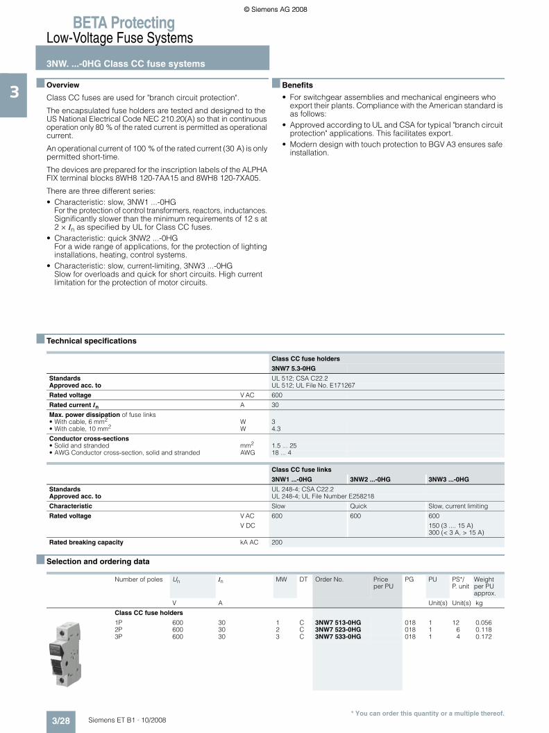
Class CC fuses are used for "branch circuit protection".
The encapsulated fuse holders are tested and designed to the US National Electrical Code NEC 210.20(A) so that in continuous operation only 80 % of the rated current is permitted as operational current.
An operational current of 100 % of the rated current (30 A) is only permitted short-time.
The devices are prepared for the inscription labels of the ALPHA FIX terminal blocks 8WH8 120-7AA15 and 8WH8 120-7XA05.
There are three different series:• Characteristic: slow, 3NW1 ...-0HG
For the protection of control transformers, reactors, inductances. Significantly slower than the minimum requirements of 12 s at 2 × In as specified by UL for Class CC fuses.
• Characteristic: quick 3NW2 ...-0HG For a wide range of applications, for the protection of lighting installations, heating, control systems.
• Characteristic: slow, current-limiting, 3NW3 ...-0HG Slow for overloads and quick for short circuits. High current limitation for the protection of motor circuits.
■ Benefits
• For switchgear assemblies and mechanical engineers who export their plants. Compliance with the American standard is as follows:
• Approved according to UL and CSA for typical "branch circuit protection" applications. This facilitates export.
• Modern design with touch protection to BGV A3 ensures safe installation.
■ Technical specifications
■ Selection and ordering data
Class CC fuse holders
3NW7 5.3-0HG
Standards UL 512; CSA C22.2Approved acc. to UL 512; UL File No. E171267
Rated voltage V AC 600
Rated current In A 30
Max. power dissipation of fuse links• With cable, 6 mm2 W 3• With cable, 10 mm2 W 4.3
Conductor cross-sections• Solid and stranded mm2 1.5 ... 25• AWG Conductor cross-section, solid and stranded AWG 18 ... 4
Class CC fuse links
3NW1 ...-0HG 3NW2 ...-0HG 3NW3 ...-0HG
Standards UL 248-4; CSA C22.2Approved acc. to UL 248-4; UL File Number E258218
Characteristic Slow Quick Slow, current limiting
Rated voltage V AC
V DC
600 600 600
150 (3 .... 15 A)300 (< 3 A, > 15 A)
Rated breaking capacity kA AC 200
Number of poles Un In MW DT Order No. Priceper PU
PG PU PS*/P. unit
Weightper PU approx.
V A Unit(s) Unit(s) kg
Class CC fuse holders
1P 600 30 1 C 3NW7 513-0HG 018 1 12 0.0562P 600 30 2 C 3NW7 523-0HG 018 1 6 0.1183P 600 30 3 C 3NW7 533-0HG 018 1 4 0.172
ET_B1_2009_en.book Seite 28 Freitag, 12. Dezember 2008 9:47 09
© Siemens AG 2008© Siemens AG 2008

BETA ProtectingLow-Voltage Fuse Systems
3NW. ...-0HG Class CC fuse systems
3/29Siemens ET B1 · 10/2008
3
* You can order this quantity or a multiple thereof.
1) Values in brackets, American English
■ Dimensional drawings
Characteristic: slow Characteristic: quick
In1) DT Order No. Price
per PUPG DT Order No. Price
per PUPG PU PS*/
P. unitWeightper PU approx.
A Unit(s) Unit(s) kg
Class CC fuse links
0.6 (6/10) C 3NW1 006-0HG 018 -- 1 10 0.0080.8 (8/10) C 3NW1 008-0HG 018 -- 1 10 0.0081 C 3NW1 010-0HG 018 C 3NW2 010-0HG 018 1 10 0.0081.5 (1 ½) C 3NW1 015-0HG 018 -- 1 10 0.008
2 C 3NW1 020-0HG 018 C 3NW2 020-0HG 018 1 10 0.0083 C 3NW1 030-0HG 018 C 3NW2 030-0HG 018 1 10 0.0084 C 3NW1 040-0HG 018 C 3NW2 040-0HG 018 1 10 0.0085 C 3NW1 050-0HG 018 C 3NW2 050-0HG 018 1 10 0.008
6 C 3NW1 060-0HG 018 C 3NW2 060-0HG 018 1 10 0.0088 C 3NW1 080-0HG 018 C 3NW2 080-0HG 018 1 10 0.00810 C 3NW1 100-0HG 018 C 3NW2 100-0HG 018 1 10 0.00812 -- C 3NW2 120-0HG 018 1 10 0.008
15 C 3NW1 150-0HG 018 C 3NW2 150-0HG 018 1 10 0.00820 C 3NW1 200-0HG 018 C 3NW2 200-0HG 018 1 10 0.00825 C 3NW1 250-0HG 018 C 3NW2 250-0HG 018 1 10 0.00830 C 3NW1 300-0HG 018 -- 1 10 0.008
Characteristic: slow,current limiting
In1) DT Order No. Price
per PUPG PU PS*/
P. unitWeightper PU approx.
A Unit(s) Unit(s) kg
Class CC fuse links
0.6 (6/10) --0.8 (8/10) --1 C 3NW3 010-0HG 018 1 10 0.0081.5 (1 ½) --
2 C 3NW3 020-0HG 018 1 10 0.0083 C 3NW3 030-0HG 018 1 10 0.0084 C 3NW3 040-0HG 018 1 10 0.0085 C 3NW3 050-0HG 018 1 10 0.008
6 C 3NW3 060-0HG 018 1 10 0.0088 C 3NW3 080-0HG 018 1 10 0.00810 C 3NW3 100-0HG 018 1 10 0.00812 C 3NW3 120-0HG 018 1 10 0.008
15 C 3NW3 150-0HG 018 1 10 0.00820 C 3NW3 200-0HG 018 1 10 0.00825 C 3NW3 250-0HG 018 1 10 0.00830 C 3NW3 300-0HG 018 1 10 0.008
3NW1 ...-0HG 3NW2 ...-0HG 3NW3 ...-0HG
3NW7 5..-0HG
38,1
I2_12159
Ø10
,3
45 81
3774958
543618
I2_1
3727
ET_B1_2009_en.book Seite 29 Freitag, 12. Dezember 2008 9:47 09
© Siemens AG 2008© Siemens AG 2008

BETA ProtectingLow-Voltage Fuse Systems5ST2, 5ST3 busbars, for fuse systems
3/30 Siemens ET B1 · 10/2008
3
* You can order this quantity or a multiple thereof.
■ Overview
Busbars with pin-type connections can be used for NEOZED safety switching devices and fuse bases. Busbars are available in 10 mm2 and 16 mm2.
Busbars with fork plugs are used for the most frequently used NEOZED fuse bases made of ceramic.
■ Benefits
• Clear and visible conductor connection that can be easily checked when using MINIZED switch disconnectors D02. This facilitates the insertion of conductors and saves time.
• Bus-mounting of MINIZED fuse switch disconnectors D01 with three-phase pin busbar, which can be cut to length. Tried and tested.
• Single-phase busbar mounting of NEOZED fuse bases. • Clear and visible conductor connection that can be easily checked when using NEOZED comfort base D02. This facilitates the insertion of conductors and saves time.
• Bus-mounting of NEOZED fuse bases made of molded plastic on three-phase busbar with fork plug, which can be cut to length. Frequently used.
• Bus-mounting of NEOZED fuse bases made of ceramic on three-phase busbar with fork plug, which can be cut to length. Most common application.
ET_B1_2009_en.book Seite 30 Freitag, 12. Dezember 2008 9:47 09
© Siemens AG 2008© Siemens AG 2008

BETA ProtectingLow-Voltage Fuse Systems
5ST2, 5ST3 busbars,for fuse systems
3/31Siemens ET B1 · 10/2008
3
* You can order this quantity or a multiple thereof.
• Bus-mounting of cylindrical fuse holders 8 x 32 mm and 10 x 38 mm with three-phase pin busbar, which can be cut to length.
• Bus-mounting of SITOR cylindrical fuse holders 10 mm × 38 mm with the same terminal connection as Class CC fuse holder with three-phase pin busbars, which can be cut to length.
■ Technical specifications
Infeed at the start of the busbar Infeed along the busbar or midpoint infeed
5ST, 5SH
Standards EN 60439-1 (VDE 0660-500): 2005-01
Busbar material SF-Cu F 24
Partition material Plastic, Cycoloy 3600 heat-resistant to more than 90 °Cflame-retardant and self-extinguishing, dioxin and halogen-free
Rated operational voltage Uc V AC 400
Rated current In
• Cross-section 10 mm2 A 63• Cross-section 16 mm2 A 80
Rated impulse withstand voltage Uimp kV 4
Test pulse voltage (1.2/50) kV 6.2
Rated conditional short-circuit current Icc kA 25
Resistance to climate
• Constant atmosphere Acc.to DIN 50015 23/83; 40/92; 55/20 • Humid heat Acc. to IEC 60068-2-30 28 cycles
Insulation coordination
• Overvoltage category III• Degree of pollution 2
Maximum busbar current IS/phase
• Infeed at the start of the busbar- Cross-section 10 mm2 A 63- Cross-section 16 mm2 A 80
• Infeed at the center of the busbar- Cross-section 10 mm2 A 100- Cross-section 16 mm2 A 130
The sum of the output current per branch must not be greater than the busbar current IS1.2 / phase.
S
I2_13755
S1 S2
3 2 1 1 2 3
I2_13754
ET_B1_2009_en.book Seite 31 Freitag, 12. Dezember 2008 9:47 09
© Siemens AG 2008© Siemens AG 2008

BETA ProtectingLow-Voltage Fuse Systems5ST2, 5ST3 busbars, for fuse systems
3/32 Siemens ET B1 · 10/2008
3
* You can order this quantity or a multiple thereof.
■ Selection and ordering data
Phases Conductor cross-section
Load capac-ity up to
Pinspacing
Length DT Order No. Priceper PU
PG PU PS*/P. unit
Weightper PU approx.
mm2 A MW mm Unit(s) Unit(s) kg
Busbars
For MINIZED switch disconnectors D02For NEOZED comfort bases D01/D02 Made of molded plastic5SG1 01, 5SG5 01
For NEOZED fuse bases D01/D02 made of ceramic,terminal version SFor cylindrical fuse holders 14 x 51 mmFor SITOR cylindrical fuse holders 14 x 51 mm,can be cut to length, without end caps
Single-phase
16 130 1.5 1016 A 5ST3 703 027 1 1 0.190
Three-phase
16 120 1.5 1016 A 5ST3 714 027 1 1 0.430
For NEOZED fuse switch disconnectors D01
Can be cut to length, without end caps
Single-phase
16 120 1 1000 B 5ST2 190 027 1 1 0.500
Two-phase
B 5ST2 191 027 1 1 0.710
Three-phase
B 5ST2 192 027 1 1 1.100
Can be cut to length, with 2 end caps
Single-phase
16 120 1 220 B 5ST2 186 027 1 1 0.090
Two-phase
B 5ST2 187 027 1 1 0.160
Three-phase
B 5ST2 188 027 1 1 0.230
For NEOZED fuse bases D01/D02 made of molded plastic5SG1 .30, 5SG1 .31, 5SG5 .30
For NEOZED fuse bases D01/D02 made of ceramic Terminal versions B and K
Non-insulated
Single-phase
20 116 1.5 1000 } 5SH5 321 016 1 1 0.214
36 168 1.5 } 5SH5 322 016 1 1 0.321
Can be cut to length, without end caps
Single-phase
24 160 1.5 1000 A 5SH5 517 016 1 1 0.550
Three-phase
16 120 1.5 1000 } 5SH5 320 016 1 1 0.843
ET_B1_2009_en.book Seite 32 Freitag, 12. Dezember 2008 9:47 09
© Siemens AG 2008© Siemens AG 2008

BETA ProtectingLow-Voltage Fuse Systems
5ST2, 5ST3 busbars,for fuse systems
3/33Siemens ET B1 · 10/2008
3
* You can order this quantity or a multiple thereof.
Phases Conductor cross-section
Load capac-ity up to
Pinspacing
Length DT Order No. Priceper PU
PG PU PS*/P. unit
Weightper PU approx.
mm2 A MW mm Unit(s) Unit(s) kg
For cylindrical fuse holders 8 × 32 mm and 10 × 38 mm For SITOR cylindrical fuse holders 10 × 38 mm For Class CC fuse holders
Can be cut to length, without end caps
Single-phase
16 120 1 1016 A 5ST3 701 027 1 1 0.190
Two-phase
120 1 A 5ST3 705 027 1 1 0.290
Three-phase
16 120 1 1016 } 5ST3 710 027 1 1 0.430
Cannot be cut to length, fully insulated
Single-phase
16 1 214 } 5ST3 700 027 1 1 0.040
Two-phase
1 A 5ST3 704 027 1 1 0.060
Three-phase
1 } 5ST3 708 027 1 1 0.100
End caps for busbars
For single-phase 5ST3 7, 5SH5 5 busbars 156 } 5ST3 748 027 1 10 0.001
For three-phase 5ST3 7 and 5SH5 320 busbars } 5ST3 750 027 1 10 0.001
Touch protection for free connection of pin busbars
Yellow, (RAL 1004) A 5ST3 655 027 1 10 0.003
Terminals
For NEOZED fuse bases D01/D02 made of ceramicFor DIAZED fuse bases DII/DIII, made of ceramicFor cylindrical fuse holders
Terminal version SFor con-ductors
2 ... 25 } 5SH5 327 016 1 10/300 0.014
Terminal versions B and KFor con-ductors
6 ... 25 } 5SH5 328 016 1 10/300 0.014
For the infeed of fork-type or pin busbarsFor con-ductors
6 ... 35 A 5ST2 157 027 1 5 0.030
ET_B1_2009_en.book Seite 33 Freitag, 12. Dezember 2008 9:47 09
© Siemens AG 2008© Siemens AG 2008

BETA ProtectingLow-Voltage Fuse Systems5ST2, 5ST3 busbars, for fuse systems
3/34 Siemens ET B1 · 10/2008
3
* You can order this quantity or a multiple thereof.
■ Dimensional drawings
Phases Conductor cross-section
Load capacity up to
Length DT Order No. Priceper PU
PG PU PS*/P. unit
Weightper PU approx.
mm2 A mm Unit(s) Unit(s) kg
Busbarsfor 1-pole DIAZED fuse bases made of ceramicwith terminal versions BB and BS
Size DII, for 19 basesSingle-phase
24 80 1000 A 5SH3 500 016 1 1/25 0.095
Size DIII, for 25 basesSingle-phase
39 120 1000 A 5SH3 501 016 1 1/25 0.180
BusbarsFor DIAZED bus-mounting bases/EZRwith thread for screw adapters
For size DII, 42 5SF6 005 basesSingle-phase
48 150 2000 C 5SH3 54 016 1 5 0.740
For size DIII, 34 5SF6 205 basesSingle-phase
48 150 2000 C 5SH3 55 016 1 5 0.740
Bus-mounting terminalsFor DIAZED EZR bus-mounting bases
Non-insulated
For con-ductors
1.5 ... 16 A 8JH4 122 046 1 10 0.012
For con-ductors
10 ... 35 A 8JH4 124 046 1 10 0.024
5ST3 7
Pin spacing in MWDimensions of side views in mm (approx.)
5ST3 700 5ST3 701
5ST3 703 5ST3 704 5ST3 705
Single-phase Single-phase
5ST3 708 5ST3 710
5ST3 714
5ST2
Fork spacing in MWDimensions of side views in mm (approx.)
5ST2 186 5ST2 190
5ST2 187 5ST2 188 5ST2 191 5ST2 192
3,5
13
1,5
I2_1
3674
1
15
18
1
L1 L2
I2_1
3748
15
18
L1 L2 L3
1 1
L1 L2 L3
1,5 1,5
I2_1
3674
9
15,1
3,5
13 I2_1
3750
ET_B1_2009_en.book Seite 34 Freitag, 12. Dezember 2008 9:47 09
© Siemens AG 2008© Siemens AG 2008

BETA ProtectingLow-Voltage Fuse Systems
5ST2, 5ST3 busbars,for fuse systems
3/35Siemens ET B1 · 10/2008
3
* You can order this quantity or a multiple thereof.
Busbars for DIAZED EZR fuse bases
5SH3 54
5SH3 55
5SH3 500 5SH3 501
5SH5 5SH5
Fork spacing in MWDimensions of side views in mm (approx.)
Fork spacing in MWDimensions of side views in mm (approx.)
5SH5 517 5SH5 320 5SH5 321 5SH5 322
4730,6 30,61927
3
16
I2_06447a
3/16"
5740 1881 40
I2_06448a
3
16
3/16"
I2_1
3426
a
52 6
6
960
1030
13
2
97 6
6
6 872
970
13
3 I2_1
3427
I2_13825
1,5
15
5
I2_13826
1,5
15
17
I2_138272
1,5
12
3
12
ET_B1_2009_en.book Seite 35 Freitag, 12. Dezember 2008 9:47 09
© Siemens AG 2008© Siemens AG 2008

BETA ProtectingLow-Voltage Fuse Systems
3NA, 3ND LV HRC fuse links
3/36 Siemens ET B1 · 10/2008
3
* You can order this quantity or a multiple thereof.
■ Overview
LV HRC fuses are used for installation systems in non-residential, commercial and industrial buildings, as well as in the switch-boards of power supply companies. They therefore protect es-sential building parts and installations.
LV HRC fuses are fuse systems designed for operation by skilled personnel. There are no constructional requirements for non-inter-changeability of rated current and touch protection.
The components and auxiliary equipment are designed in such a way as to ensure the safe replacement of LV HRC fuses or isolation of systems.
LV HRC fuse links are available in the sizes 000, 00, 0, 1, 2, 3, 4 and 4a.
LV HRC fuse links are available in the following operational classes:• gG for cable and line protection• aM for the short-circuit protection of switching devices in
motor circuits • gR or aR for the protection of power semiconductors • gS: The new gS operational class combines cable and line
protection with semiconductor protection.
LV HRC fuse links of size 000 can also be used in LV HRC fuse bases, LV HRC fuse switch disconnectors, LV HRC fuse strips as well as in LV HRC in-line fuse switch disconnectors of size 00.
The fuse links 300 A, 355 A and 425 A comply with the standard but do not have the VDE mark.
LV HRC components:
$ LV HRC fuse base from the SR60 busbar system% LV HRC fuse base for busbar mounting& LV HRC fuse base, 3P( LV HRC fuse base, 1P) LV HRC contact cover* LV HRC fuse link+ LV HRC signal detector, LV HRC partition- LV HRC protective cover
LV HRC fuse bases with swivel mechanism. - For screw fixing on mounting plate/ - For screw fixing on busbar system 0 - For claw fixing on busbar1 LV HRC protective cover for LV HRC fuse bases with swivel
mechanism
2 LV HRC swivel mechanism3 LV HRC fuse base cover4 LV HRC isolating link with insulated grip lugs5 LV HRC isolating link with non-insulated grip lugs6 LV HRC fuse puller with sleeve7 LV HRC fuse pullerI2_13743
1
23
45
6
15 16 17 18 19
10 11 12
14
13
9
8
7
ET_B1_2009_en.book Seite 36 Freitag, 12. Dezember 2008 9:47 09
© Siemens AG 2008© Siemens AG 2008

BETA ProtectingLow-Voltage Fuse Systems
3NA, 3ND LV HRC fuse links
3/37Siemens ET B1 · 10/2008
3
* You can order this quantity or a multiple thereof.
■ Benefits
• LV HRC fuse links with combination alarm signal the tripping of a fuse by a clear color change from red to white. This enables fast identification and replacement of the tripped fuse links. This increases plant availability.
• The insulated grip lugs made of metal are integrated in the top and bottom covers of the fuse link in molded plastic and provide greater safety when replacing. The mark shown below indicates that the grip lugs are insulated .
• In the standard series with front indicator, the front-mounted red indicator signals the tripping of a fuse.
• LV HRC fuse links are always equipped with silver-plated contact blades. This means that they are non-corroding and have less contact resistance. This ensures the long-term operational safety of the plant.
■ Technical specifications
Tripped Not tripped Tripped Not tripped
LV HRC fuse links
Operational class
Operational class
gG aM
3NA6 ...-4 3NA6 ... 3NA3 ... 3NA6 ...-6 3NA3 ...-6 3ND13NA6 ...-4KK 3NA6 ...-7 3NA3 ...-7 3NA7 ...-6 3ND23NY1 8.. 3NA7 ...
3NA7 ...-7
Standards IEC 60269-1, -2; EN 60269-1; DIN VDE 0636Approved acc. to DIN VDE 0636-2; CSA 22.2 No.106, File No. 1710842
Rated voltage Un
• Sizes 000 and 00 V AC 400 500 500 690 690 500
V DC -- 250 250 250 250 --
• Sizes 1 and 2 V AC 400 500 500 690 690 690
V DC -- 440 440 440 440 --
• Size 3 V AC 500 690 690
V DC 440 --
• Sizes (IEC design) V AC 500 --
4 and 4a V DC 400 --
Rated current In A 10 ... 400 2 ... 400 2 ... 1250 2 ... 315 2 ... 500 6 ... 630
Rated breaking capacity kA AC 120
kA DC -- 25 --
Contact pins Non-corroding, silver-plated
Resistance to climate °C -20 ... +50 at 95% relative humidity
ET_B1_2009_en.book Seite 37 Freitag, 12. Dezember 2008 9:47 09
© Siemens AG 2008© Siemens AG 2008

BETA ProtectingLow-Voltage Fuse Systems
3NA, 3ND LV HRC fuse links
3/38 Siemens ET B1 · 10/2008
3
* You can order this quantity or a multiple thereof.
■ Selection and ordering data
Insulated grip lugs
Sizes Mounting width In Un DT Order No. Priceper PU
PG PU PS*/P. unit
Weightper PU approx.
mm A V AC/V DC
Unit(s) Unit(s) kg
LV HRC fuse links with combination alarm, operational class gG
000 21 10 400/-- B 3NA6 803-4 013 1 3 0.13516 B 3NA6 805-4 013 1 3 0.13520 B 3NA6 807-4 013 1 3 0.135
25 B 3NA6 810-4 013 1 3 0.13532 B 3NA6 812-4 013 1 3 0.13535 B 3NA6 814-4 013 1 3 0.135
40 B 3NA6 817-4 013 1 3 0.13550 B 3NA6 820-4 013 1 3 0.13563 B 3NA6 822-4 013 1 3 0.135
80 B 3NA6 824-4 013 1 3 0.135100 B 3NA6 830-4 013 1 3 0.135
00 30 80 400/-- B 3NA6 824-4KK 013 1 3 0.200100 B 3NA6 830-4KK 013 1 3 0.200
125 B 3NA6 832-4 013 1 3 0.200160 B 3NA6 836-4 013 1 3 0.200
1 30 35 400/-- B 3NA6 114-4 013 1 3 0.29040 B 3NA6 117-4 013 1 3 0.29050 B 3NA6 120-4 013 1 3 0.290
63 B 3NA6 122-4 013 1 3 0.29080 B 3NA6 124-4 013 1 3 0.290
100 B 3NA6 130-4 013 1 3 0.290
125 B 3NA6 132-4 013 1 3 0.290160 B 3NA6 136-4 013 1 3 0.290
47.2 200 B 3NA6 140-4 013 1 3 0.430224 B 3NA6 142-4 013 1 3 0.430250 B 3NA6 144-4 013 1 3 0.430
2 47.2 50 400/-- B 3NA6 220-4 013 1 3 0.45063 B 3NA6 222-4 013 1 3 0.45080 B 3NA6 224-4 013 1 3 0.450
100 B 3NA6 230-4 013 1 3 0.450125 B 3NA6 232-4 013 1 3 0.450160 B 3NA6 236-4 013 1 3 0.450
200 B 3NA6 240-4 013 1 3 0.450224 B 3NA6 242-4 013 1 3 0.450250 B 3NA6 244-4 013 1 3 0.450
57.8 300 B 3NA6 250-4 013 1 3 0.650315 B 3NA6 252-4 013 1 3 0.650355 B 3NA6 254-4 013 1 3 0.650400 B 3NA6 260-4 013 1 3 0.650
ET_B1_2009_en.book Seite 38 Freitag, 12. Dezember 2008 9:47 09
© Siemens AG 2008© Siemens AG 2008

BETA ProtectingLow-Voltage Fuse Systems
3NA, 3ND LV HRC fuse links
3/39Siemens ET B1 · 10/2008
3
* You can order this quantity or a multiple thereof.
Non-insulated grip lugs Insulated grip lugs
Size Moun-ting width
In Un DT Order No. Priceper PU
PG DT Order No. Priceper PU
PG PU PS*/P. unit
Weightper PU approx.
A V AC/V DC
Unit(s) Unit(s) kg
LV HRC fuse links with combination alarm, operational class gG
000 21 2 500/ 250
B 3NA7 802 013 B 3NA6 802 013 1 3 0.1354 B 3NA7 804 013 B 3NA6 804 013 1 3 0.1356 B 3NA7 801 013 B 3NA6 801 013 1 3 0.135
10 B 3NA7 803 013 B 3NA6 803 013 1 3 0.13616 } 3NA7 805 013 } 3NA6 805 013 1 3 0.13620 } 3NA7 807 013 } 3NA6 807 013 1 3 0.136
25 } 3NA7 810 013 } 3NA6 810 013 1 3 0.60032 B 3NA7 812 013 B 3NA6 812 013 1 3 0.13635 } 3NA7 814 013 } 3NA6 814 013 1 3 0.440
40 B 3NA7 817 013 B 3NA6 817 013 1 3 0.13650 } 3NA7 820 013 } 3NA6 820 013 1 3 0.12863 } 3NA7 822 013 } 3NA6 822 013 1 3 0.120
80 } 3NA7 824 013 } 3NA6 824 013 1 3 0.128100 } 3NA7 830 013 } 3NA6 830 013 1 3 0.120
00 30 80 500/ 250
B 3NA7 824-7 013 B 3NA6 824-7 013 1 3 0.211100 B 3NA7 830-7 013 B 3NA6 830-7 013 1 3 0.211125 } 3NA7 832 013 } 3NA6 832 013 1 3 0.200
160 } 3NA7 836 013 A 3NA6 836 013 1 3 0.200
1 30 16 500/ 440
B 3NA7 105 013 B 3NA6 105 013 1 3 0.29020 B 3NA7 107 013 B 3NA6 107 013 1 3 0.29025 B 3NA7 110 013 B 3NA6 110 013 1 3 0.290
35 B 3NA7 114 013 B 3NA6 114 013 1 3 0.29040 B 3NA7 117 013 B 3NA6 117 013 1 3 0.29050 B 3NA7 120 013 B 3NA6 120 013 1 3 0.290
63 B 3NA7 122 013 B 3NA6 122 013 1 3 0.29080 B 3NA7 124 013 } 3NA6 124 013 1 3 0.290
100 B 3NA7 130 013 } 3NA6 130 013 1 3 0.290
125 } 3NA7 132 013 } 3NA6 132 013 1 3 0.290160 } 3NA7 136 013 } 3NA6 136 013 1 3 0.290
47.2 200 } 3NA7 140 013 } 3NA6 140 013 1 3 0.440224 B 3NA7 142 013 B 3NA6 142 013 1 3 0.440250 } 3NA7 144 013 } 3NA6 144 013 1 3 0.400
2 47.2 35 500/ 440
B 3NA7 214 013 B 3NA6 214 013 1 3 0.45050 B 3NA7 220 013 B 3NA6 220 013 1 3 0.45063 B 3NA7 222 013 B 3NA6 222 013 1 3 0.450
80 B 3NA7 224 013 B 3NA6 224 013 1 3 0.450100 B 3NA7 230 013 B 3NA6 230 013 1 3 0.450125 B 3NA7 232 013 B 3NA6 232 013 1 3 0.450
160 } 3NA7 236 013 } 3NA6 236 013 1 3 0.450200 } 3NA7 240 013 } 3NA6 240 013 1 3 0.450
224 B 3NA7 242 013 B 3NA6 242 013 1 3 0.450250 } 3NA7 244 013 } 3NA6 244 013 1 3 0.450
57.8 300 -- B 3NA6 250 013 1 3 0.641 315 } 3NA7 252 013 } 3NA6 252 013 1 3 0.660
355 -- B 3NA6 254 013 1 3 0.641400 } 3NA7 260 013 } 3NA6 260 013 1 3 0.660
ET_B1_2009_en.book Seite 39 Freitag, 12. Dezember 2008 9:47 09
© Siemens AG 2008© Siemens AG 2008

BETA ProtectingLow-Voltage Fuse Systems
3NA, 3ND LV HRC fuse links
3/40 Siemens ET B1 · 10/2008
3
* You can order this quantity or a multiple thereof.
Non-insulated grip lugs
Sizes Mounting width In Un DT Order No. Priceper PU
PG PU PS*/P. unit
Weightper PU approx.
mm A V AC/V DC
Unit(s) Unit(s) kg
LV HRC fuse links with front indicator, operational class gG
000 21 2 500/250 } 3NA3 802 013 1 3 0.1334 } 3NA3 804 013 1 3 0.1336 } 3NA3 801 013 1 3 0.133
10 } 3NA3 803 013 1 3 0.13316 } 3NA3 805 013 1 3 0.13320 } 3NA3 807 013 1 3 0.133
25 } 3NA3 810 013 1 3 0.13332 } 3NA3 812 013 1 3 0.13335 } 3NA3 814 013 1 3/90 0.133
40 } 3NA3 817 013 1 3 0.13350 } 3NA3 820 013 1 3/90 0.13363 } 3NA3 822 013 1 3/90 0.133
80 } 3NA3 824 013 1 3/90 0.133100 } 3NA3 830 013 1 3/90 0.133
125 } 3NA3 832-8 013 1 3 0.160160 400/250 } 3NA3 836-8 013 1 3 0.160
00 30 35 500/250 B 3NA3 814-7 013 1 3 0.20050 B 3NA3 820-7 013 1 3 0.20063 B 3NA3 822-7 013 1 3 0.200
80 B 3NA3 824-7 013 1 3 0.200100 B 3NA3 830-7 013 1 3 0.200125 } 3NA3 832 013 1 3 0.217
160 } 3NA3 836 013 1 3 0.217
0 30 6 500/440 B 3NA3 001 013 1 3 0.34010 B 3NA3 003 013 1 3 0.34016 B 3NA3 005 013 1 3 0.340
20 B 3NA3 007 013 1 3 0.34025 B 3NA3 010 013 1 3 0.34032 B 3NA3 012 013 1 3 0.340
35 B 3NA3 014 013 1 3 0.34040 B 3NA3 017 013 1 3 0.34050 B 3NA3 020 013 1 3 0.340
63 A 3NA3 022 013 1 3 0.34080 B 3NA3 024 013 1 3 0.340
100 A 3NA3 030 013 1 3 0.340
125 A 3NA3 032 013 1 3 0.340160 A 3NA3 036 013 1 3 0.340
1 30 16 500/440 B 3NA3 105 013 1 3 0.29020 B 3NA3 107 013 1 3 0.29025 B 3NA3 110 013 1 3 0.290
35 B 3NA3 114 013 1 3 0.30040 B 3NA3 117 013 1 3 0.30050 B 3NA3 120 013 1 3 0.300
63 } 3NA3 122 013 1 3 0.30080 } 3NA3 124 013 1 3 0.300
100 } 3NA3 130 013 1 3 0.300
125 } 3NA3 132 013 1 3 0.300160 } 3NA3 136 013 1 3 0.300
47.2 200 } 3NA3 140 013 1 3 0.440224 A 3NA3 142 013 1 3 0.440250 } 3NA3 144 013 1 3 0.440
ET_B1_2009_en.book Seite 40 Freitag, 12. Dezember 2008 9:47 09
© Siemens AG 2008© Siemens AG 2008

BETA ProtectingLow-Voltage Fuse Systems
3NA, 3ND LV HRC fuse links
3/41Siemens ET B1 · 10/2008
3
* You can order this quantity or a multiple thereof.
Non-insulated grip lugs
Sizes Mounting width
In Un DT Order No. Priceper PU
PG PU PS*/P. unit
Weightper PU approx.
mm A V AC/V DC
Unit(s) Unit(s) kg
LV HRC fuse links with front indicator, operational class gG
2 47.2 35 500/440 B 3NA3 214 013 1 3 0.45350 B 3NA3 220 013 1 3 0.45363 A 3NA3 222 013 1 3 0.453
80 A 3NA3 224 013 1 3 0.453100 A 3NA3 230 013 1 3 0.453125 A 3NA3 232 013 1 3 0.453
160 } 3NA3 236 013 1 3 0.453200 } 3NA3 240 013 1 3 0.453
224 } 3NA3 242 013 1 3 0.453250 } 3NA3 244 013 1 3 0.453
57.8 300 A 3NA3 250 013 1 3 0.647315 } 3NA3 252 013 1 3 0.647
355 } 3NA3 254 013 1 3 0.647400 } 3NA3 260 013 1 3 0.647
3 57.8 200 500/440 B 3NA3 340 013 1 3 0.647224 B 3NA3 342 013 1 3 0.640250 A 3NA3 344 013 1 3 0.647
300 B 3NA3 350 013 1 3 0.647315 } 3NA3 352 013 1 3 0.647
355 A 3NA3 354 013 1 3 0.647400 } 3NA3 360 013 1 3 0.647
71.2 425 A 3NA3 362 013 1 3 1.000500 } 3NA3 365 013 1 3 1.000630 } 3NA3 372 013 1 3 1.000
Can only be used for 3NH3 530 LV HRC fuse base
4 (IEC design) 101.8 630 500/440 B 3NA3 472 013 1 1 2.500800 A 3NA3 475 013 1 1 2.500
1000 A 3NA3 480 013 1 1 2.500
1250 A 3NA3 482 013 1 1 2.500
Can only be used for 3NH7 520 LV HRC fuse base
4a 101.8 500 500/440 B 3NA3 665 013 1 1 2.700630 B 3NA3 672 013 1 1 2.700800 A 3NA3 675 013 1 1 2.700
1000 A 3NA3 680 013 1 1 2.8401250 A 3NA3 682 013 1 1 2.840
ET_B1_2009_en.book Seite 41 Freitag, 12. Dezember 2008 9:47 09
© Siemens AG 2008© Siemens AG 2008

BETA ProtectingLow-Voltage Fuse Systems
3NA, 3ND LV HRC fuse links
3/42 Siemens ET B1 · 10/2008
3
* You can order this quantity or a multiple thereof.
Non-insulated grip lugs Insulated grip lugs
Size Moun-ting width
In Un DT Order No. Priceper PU
PG DT Order No. Priceper PU
PG PU PS*/P. unit
Weightper PU approx.
A V AC/V DC
Unit(s) Unit(s) kg
LV HRC fuse links with combination alarm, operational class gG
000 21 2 690/ 250
B 3NA7 802-6 013 B 3NA6 802-6 013 1 3 0.1364 B 3NA7 804-6 013 B 3NA6 804-6 013 1 3 0.1366 B 3NA7 801-6 013 B 3NA6 801-6 013 1 3 0.136
10 B 3NA7 803-6 013 B 3NA6 803-6 013 1 3 0.13616 B 3NA7 805-6 013 B 3NA6 805-6 013 1 3 0.13620 B 3NA7 807-6 013 B 3NA6 807-6 013 1 3 0.136
25 B 3NA7 810-6 013 B 3NA6 810-6 013 1 3 0.13632 B 3NA7 812-6 013 B 3NA6 812-6 013 1 3 0.13635 B 3NA7 814-6 013 B 3NA6 814-6 013 1 3 0.136
00 30 40 690/ 250
B 3NA7 817-6 013 B 3NA6 817-6 013 1 3 0.21150 B 3NA7 820-6 013 B 3NA6 820-6 013 1 3 0.21163 B 3NA7 822-6 013 B 3NA6 822-6 013 1 3 0.211
80 B 3NA7 824-6 013 B 3NA6 824-6 013 1 3 0.211100 B 3NA7 830-6 013 B 3NA6 830-6 013 1 3 0.211
1 30 50 690/ 440
B 3NA7 120-6 013 B 3NA6 120-6 013 1 3 0.29063 B 3NA7 122-6 013 B 3NA6 122-6 013 1 3 0.29080 B 3NA7 124-6 013 B 3NA6 124-6 013 1 3 0.290
100 B 3NA7 130-6 013 B 3NA6 130-6 013 1 3 0.290125 B 3NA7 132-6 013 B 3NA6 132-6 013 1 3 0.290160 B 3NA7 136-6 013 B 3NA6 136-6 013 1 3 0.290
47.2 200 B 3NA7 140-6 013 B 3NA6 140-6 013 1 3 0.440
2 47.2 80 690/ 440
B 3NA7 224-6 013 B 3NA6 224-6 013 1 3 0.450100 B 3NA7 230-6 013 B 3NA6 230-6 013 1 3 0.450125 B 3NA7 232-6 013 B 3NA6 232-6 013 1 3 0.450
160 B 3NA7 236-6 013 B 3NA6 236-6 013 1 3 0.450200 B 3NA7 240-6 013 B 3NA6 240-6 013 1 3 0.450
57.8 224 B 3NA7 242-6 013 B 3NA6 242-6 013 1 3 0.660250 B 3NA7 244-6 013 B 3NA6 244-6 013 1 3 0.660
300 B 3NA7 250-6 013 B 3NA6 250-6 013 1 3 0.660315 B 3NA7 252-6 013 B 3NA6 252-6 013 1 3 0.660
ET_B1_2009_en.book Seite 42 Freitag, 12. Dezember 2008 9:47 09
© Siemens AG 2008© Siemens AG 2008

BETA ProtectingLow-Voltage Fuse Systems
3NA, 3ND LV HRC fuse links
3/43Siemens ET B1 · 10/2008
3
* You can order this quantity or a multiple thereof.
Non-insulated grip lugs
Sizes Mounting width
In Un DT Order No. Priceper PU
PG PU PS*/P. unit
Weightper PU approx.
mm A V AC/V DC
Unit(s) Unit(s) kg
LV HRC fuse links with front indicator, operational class gG
000 21 2 690/250 } 3NA3 802-6 013 1 3 0.1354 } 3NA3 804-6 013 1 3 0.1356 } 3NA3 801-6 013 1 3 0.135
10 } 3NA3 803-6 013 1 3 0.13516 } 3NA3 805-6 013 1 3 0.13520 } 3NA3 807-6 013 1 3 0.135
25 } 3NA3 810-6 013 1 3 0.13532 B 3NA3 812-6 013 1 3 0.13535 } 3NA3 814-6 013 1 3 0.135
00 30 40 690/250 B 3NA3 817-6 013 1 3 0.20050 } 3NA3 820-6 013 1 3 0.20063 } 3NA3 822-6 013 1 3 0.200
80 } 3NA3 824-6 013 1 3 0.200100 } 3NA3 830-6 013 1 3 0.200
1 30 50 690/440 B 3NA3 120-6 013 1 3 0.29063 B 3NA3 122-6 013 1 3 0.29080 B 3NA3 124-6 013 1 3 0.290
100 } 3NA3 130-6 013 1 3 0.290125 } 3NA3 132-6 013 1 3 0.290160 } 3NA3 136-6 013 1 3 0.290
47.2 200 } 3NA3 140-6 013 1 3 0.426
2 47.2 80 690/440 B 3NA3 224-6 013 1 3 0.426100 B 3NA3 230-6 013 1 3 0.426125 B 3NA3 232-6 013 1 3 0.426
160 } 3NA3 236-6 013 1 3 0.426200 } 3NA3 240-6 013 1 3 0.426
57.8 224 B 3NA3 242-6 013 1 3 0.660250 } 3NA3 244-6 013 1 3 0.680
300 B 3NA3 250-6 013 1 3 0.660315 } 3NA3 252-6 013 1 3 0.680
3 57.8 250 690/440 B 3NA3 344-6 013 1 3 0.660315 B 3NA3 352-6 013 1 3 0.660
71.2 355 B 3NA3 354-6 013 1 3 1.000400 } 3NA3 360-6 013 1 3 1.000
425 B 3NA3 362-6 013 1 3 1.000500 } 3NA3 365-6 013 1 3 1.000
ET_B1_2009_en.book Seite 43 Freitag, 12. Dezember 2008 9:47 09
© Siemens AG 2008© Siemens AG 2008
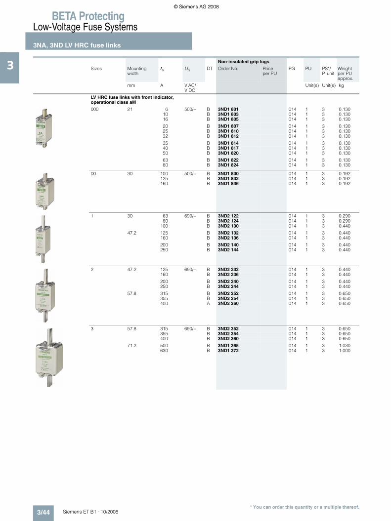
BETA ProtectingLow-Voltage Fuse Systems
3NA, 3ND LV HRC fuse links
3/44 Siemens ET B1 · 10/2008
3
* You can order this quantity or a multiple thereof.
Non-insulated grip lugs
Sizes Mounting width
In Un DT Order No. Priceper PU
PG PU PS*/P. unit
Weightper PU approx.
mm A V AC/V DC
Unit(s) Unit(s) kg
LV HRC fuse links with front indicator, operational class aM
000 21 6 500/-- B 3ND1 801 014 1 3 0.13010 B 3ND1 803 014 1 3 0.13016 B 3ND1 805 014 1 3 0.130
20 B 3ND1 807 014 1 3 0.13025 B 3ND1 810 014 1 3 0.13032 B 3ND1 812 014 1 3 0.130
35 B 3ND1 814 014 1 3 0.13040 B 3ND1 817 014 1 3 0.13050 B 3ND1 820 014 1 3 0.130
63 B 3ND1 822 014 1 3 0.13080 B 3ND1 824 014 1 3 0.130
00 30 100 500/-- B 3ND1 830 014 1 3 0.192125 B 3ND1 832 014 1 3 0.192160 B 3ND1 836 014 1 3 0.192
1 30 63 690/-- B 3ND2 122 014 1 3 0.29080 B 3ND2 124 014 1 3 0.290
100 B 3ND2 130 014 1 3 0.440
47.2 125 B 3ND2 132 014 1 3 0.440160 B 3ND2 136 014 1 3 0.440
200 B 3ND2 140 014 1 3 0.440250 B 3ND2 144 014 1 3 0.440
2 47.2 125 690/-- B 3ND2 232 014 1 3 0.440160 B 3ND2 236 014 1 3 0.440
200 B 3ND2 240 014 1 3 0.440250 B 3ND2 244 014 1 3 0.440
57.8 315 B 3ND2 252 014 1 3 0.650355 B 3ND2 254 014 1 3 0.650400 A 3ND2 260 014 1 3 0.650
3 57.8 315 690/-- B 3ND2 352 014 1 3 0.650355 B 3ND2 354 014 1 3 0.650400 B 3ND2 360 014 1 3 0.650
71.2 500 B 3ND1 365 014 1 3 1.030630 B 3ND1 372 014 1 3 1.000
ET_B1_2009_en.book Seite 44 Freitag, 12. Dezember 2008 9:47 09
© Siemens AG 2008© Siemens AG 2008

BETA ProtectingLow-Voltage Fuse Systems
3NA, 3ND LV HRC fuse links
3/45Siemens ET B1 · 10/2008
3
* You can order this quantity or a multiple thereof.
■ Dimensional drawings
LV HRC fuse links, operational class gG
Size In Un Type Dimensions
A V b h1 h2 t1 t2Sizes 000 to 3 and 4a 000 2 ... 35 690 V AC/ 250 V DC 3NA3 8..-6 21 54 80 45 8
2 ... 160 500 V AC 3NA3 8../-82 ... 100 500 V AC/250 V DC 3NA6 8..
10 ... 100 400 V AC 3NA6 8..-42 ... 35 690 V AC/250 V DC 3NA6 8..-6
10 ... 100 500 V AC/250 V DC 3NA7 8..2 ... 35 690 V AC/250 V DC 3NA7 8..-6
00 35 ... 160 500 V AC/250 V DC 3NA3 8.. 30 54 80 45 1440 ... 100 690 V AC/250 V DC 3NA3 8..-680 ... 160 500 V AC/250 V DC 3NA6 8../-780 ... 160 400 V AC 3NA6 8..-4 (KK)40 ... 100 690 V AC/250 V DC 3NA6 8..-680 ... 160 500 V AC/250 V DC 3NA7 8../-740 ... 100 690 V AC/250 V DC 3NA7 8..-6
Size 4 (IEC design) 0 6 ... 160 500 V AC/440 V DC 3NA3 0.. 30 67 126 45 14
1 16 ... 160 500 V AC/440 V DC 3NA3 1.. 30 75 137 50 1550 ... 160 690 V AC/440 V DC 3NA3 1..-616 ... 160 500 V AC/440 V DC 3NA6 1..35 ... 160 400 V AC 3NA6 1..-450 ... 160 690 V AC/440 V DC 3NA6 1..-616 ... 160 500 V AC/440 V DC 3NA7 1..50 ... 160 690 V AC/440 V DC 3NA7 1..-6
200 ... 250 500 V AC/440 V DC 3NA3 1.. 47 75 137 51 9200 690 V AC/440 V DC 3NA3 1..-6200 ... 250 500 V AC/440 V DC 3NA6 1..200 ... 250 400 V AC 3NA6 1..-4200 690 V AC/440 V DC 3NA6 1..-6200 ... 250 500 V AC/440 V DC 3NA7 1..200 690 V AC/440 V DC 3NA7 1..-6
2 35 ... 250 500 V AC/440 V DC 3NA3 2.. 47 75 151 58 1080 ... 200 690 V AC/440 V DC 3NA3 2..-635 ... 250 500 V AC/440 V DC 3NA6 2..50 ... 250 400 V AC 3NA6 2..-480 ... 200 690 V AC/440 V DC 3NA6 2..-635 ... 250 500 V AC/440 V DC 3NA7 2..80 ... 200 690 V AC/440 V DC 3NA7 2..-6
300 ... 400 500 V AC/440 V DC 3NA3 2.. 58 74 151 59 13224 ... 250 690 V AC/440 V DC 3NA3 2..-6300 ... 400 500 V AC/440 V DC 3NA6 2..300 ... 400 400 V AC 3NA6 2..-4224 ... 315 690 V AC/440 V DC 3NA6 2..-6300 ... 400 500 V AC/440 V DC 3NA7 2..224 ... 315 690 V AC/440 V DC 3NA7 2..-6
3 200 ... 400 500 V AC/440 V DC 3NA3 3.. 58 74 151 71 13250, 315 690 V AC/440 V DC 3NA3 3..-6
425 ... 630 500 V AC/440 V DC 3NA3 3.. 71 74 151 70 13355 ... 500 690 V AC/440 V DC 3NA3 3..-6
4 630 ... 1250 500 V AC/440 V DC 3NA3 4.. See adjacent drawing
4a 500 ... 1250 500 V AC/440 V DC 3NA3 6.. 102 97 201 95 20
t1
I2_10899
b
t2
h 1 h 2
202
I2_11335
65 55
9010
2
ET_B1_2009_en.book Seite 45 Freitag, 12. Dezember 2008 9:47 09
© Siemens AG 2008© Siemens AG 2008

BETA ProtectingLow-Voltage Fuse Systems
3NA, 3ND LV HRC fuse links
3/46 Siemens ET B1 · 10/2008
3
* You can order this quantity or a multiple thereof.
LV HRC fuse links, operational class aM
Size In Un Type Dimensions
Size 000 to 3 A V b h1 h2 t1 t2000 6 ... 80 500 V AC 3ND1 8.. 21 54 80 45 8
00 100 ... 160 30 54 80 45 14
1 63 ... 100 690 V AC 3ND2 1.. 30 75 137 50 15
125 ... 250 47 75 137 51 9
2 125 ... 250 690 V AC 3ND2 2.. 47 75 151 58 10
315 ... 400 58 74 151 59 13
3 315 ... 400 690 V AC 3ND2 3.. 58 74 151 71 13
500, 630 3ND1 3.. 71 74 151 70 13
t1
I2_10899
b
t2
h 1 h 2
ET_B1_2009_en.book Seite 46 Freitag, 12. Dezember 2008 9:47 09
© Siemens AG 2008© Siemens AG 2008

BETA ProtectingLow-Voltage Fuse Systems
3NX1 LV HRC signal detectors
3/47Siemens ET B1 · 10/2008
3
* You can order this quantity or a multiple thereof.
■ Overview
LV HRC signal detectors are used for remote indication that the LV HRC fuse links have been tripped. Three different solutions are available:• 3NX1 021 signal detectors with signal detector link 3The LV HRC signal detectors with signal detector link support monitoring of LV HRC fuse links with non-insulated grip lugsof sizes 000 to 4 at 10 A or more. The signal detector link is connected in parallel to the LV HRC fuse link. In the event of a fault, the LV HRC fuse links are released simultaneously with the LV HRC fuse signaling link.A tripping pin switches a floating microswitch
• 3NX1 024 signal detector topThe signal detector top can be used with LV HRC fuse links, siz-es 000, 00, 1 and 2, which are equipped with non-insulated grip lugs and have a front indicator or combination alarm. It is simply plugged into the grip lugs• 5TT3 170 fuse monitorsIf a fuse is tripped, the front indicator springs open and switches a floating microswitch. This solution should not be used for safe-ty-relevant plants. For this purpose, we recommend our electron-ic fuse monitors.
■ Benefits
Uniform solution for all sizes
LV HRC signal detectors reliably indicate when a fuse has tripped. Tripped fuses are quickly located. This saves time and increases plant availability.
The LV HRC signal detector top is a cost-effective solution for the monitoring of Siemens LV HRC fuse links of sizes 000, 00, 1 and 2.
■ Selection and ordering data
$ LV HRC fuse link
% LV HRC signal detector
& Microswitch
( Spring contact
) Hinged lid
* Signal detector link
I2_1
3744
1
6
5
3
4
2
$ LV HRC fuse link
% Front indicator
& Signal detector top
( Rocker/lever arm
$
%
&
(
Sizes DT Order No. Priceper PU
PG PU PS*/P. unit
Weightper PU approx.
Unit(s) Unit(s) kg
LV HRC signal detectors 000 ... 4 A 3NX1 021 014 1 1 0.036Only for SIEMENS 3NA3, 3NA7 and 3ND LV HRC fuse links with non-insulated grip lugs• Rated voltage up to
690 V AC/600 V DC• Contact: microswitches 250 V AC, 6 A• Connection: flat termination 2.3 mm
Signal detector links 000 ... 4• Rated voltage up to
690 V AC/ 600 V DCResponse value > 9 V; 2.5 A; For standard applications
A 3NX1 022 014 1 3 0.015
Response value > 2 V; 7 A; Only for meshed networks
C 3NX1 023 014 1 3 0.015
Signal detector tops 000, 00, 1, 2 } 3NX1 024 014 1 1 0.010
Only for SIEMENS 3NA3, 3NA7 and 3ND LV HRC fuse links with non-insulated grip lugs• Rated voltage up to 690 V AC/600 V DC• Contact: Microswitches 230 V AC, 5 A, 1 W• Connection: flat termination 2.3 mm
ET_B1_2009_en.book Seite 47 Freitag, 12. Dezember 2008 9:47 09
© Siemens AG 2008© Siemens AG 2008

BETA ProtectingLow-Voltage Fuse Systems
3NX1 LV HRC signal detectors
3/48 Siemens ET B1 · 10/2008
3
* You can order this quantity or a multiple thereof.
For more information on fuse monitors, please refer to the chapter "Monitoring of electrical values".
■ Dimensional drawings
■ Schematics
Ue In Uc MW DT Order No. Priceper PU
PG PU PS*/P. unit
Weightper PU approx.
V AC A V Unit(s) Unit(s) kg
Fuse monitors
For all low-voltage fuse systems.Can be used in asymmetric systems afflicted with harmonics and regenerative feedback motors. Signal also for disconnected loads.
230 4 3 380 ... 415 AC 2 } 5TT3 170 027 1 1 0.150
LV HRC signal detector Signal detector link Signal detector top
3NX1 021 3NX1 022, 3NX1 023 3NX1 024
Fuse monitor
5TT3 170
LV HRC signal detectorSignal detector top
Fuse monitor
3NX1 0213NX1 024
5TT3 170
115
40
I2_0
7856
a
2515
I2_0
7857
a
11
7
66
� �
� � � �
��
����
� � � �
����
��
� � � � � �
36
L1 L2 L3
14
L1 L2 L3
15
5 4364
45 90
I2_1
1512
� �N NO NC
���� ����
�����������
ET_B1_2009_en.book Seite 48 Freitag, 12. Dezember 2008 9:47 09
© Siemens AG 2008© Siemens AG 2008

BETA ProtectingLow-Voltage Fuse Systems
3NH LV HRC fuse bases
3/49Siemens ET B1 · 10/2008
3
* You can order this quantity or a multiple thereof.
■ Overview
Terminals for all applications
Terminals are as different as the requirements of individual systems.
Flat terminals with screws are suitable for connecting busbars or cable lugs. They have a torsion-proof screw connection with shim, spring washer and nut. When tightening the nut, always ensure compliance with the specified torque due to the consid-erable leverage effect.The double busbar terminal differs from the flat terminal in that it supports connection of two busbars, one on the top and one at the bottom of the flat terminal.
The modern box terminal ensures efficient and reliable connection to the conductors. They support connection of conductors with or without end sleeves.
In the case of flat terminals with nuts, connection of the nut to the terminal lug is torsion-proof. When tightening the nut, the torque must be observed because of the considerable leverage effect.
Up to three conductors can be clamped to the terminal strip.
The plug-in terminal is equipped for connecting two conductors. One conductor can be clamped to the saddle-type terminal.
ET_B1_2009_en.book Seite 49 Freitag, 12. Dezember 2008 9:47 09
© Siemens AG 2008© Siemens AG 2008

BETA ProtectingLow-Voltage Fuse Systems
3NH LV HRC fuse bases
3/50 Siemens ET B1 · 10/2008
3
* You can order this quantity or a multiple thereof.
■ Benefits
■ Technical specifications
• The silver-plated Lyra contact provides a large contact area for the contact blade of the LV HRC fuse link. This improves heat transmission and lowers the temperature. It also mini-mizes aging of the fuse link in the maximum load range, in particular when using SITOR fuses
• The large contact area also facilitates replacement of LV HRC fuse links
• The spring washer that tensions the contact is mechanically galvanized. This prevents hydrogen embrittlement. The con-tact is resistant to aging and there will be no dreaded annealing of contacts, which considerably improves operating safety.
LV HRC fuse bases, LV HRC bus-mounting bases
Size 000/00 0 1 2 3 4
Standards IEC 60269-1, -2; EN 60269-1; DIN VDE 0636-2
Rated current In A 160 160 250 400 630 1250
Rated voltage Un V AC 690 690 (Also suitable for 1000 V SITOR fuse links)V DC 250 440
Rated breaking capacity kA AC 120
kA DC 25
Flat terminals
Screw M8 M10 M12Nut M8 --Max. tightening torque Nm 14 38 65
Plug-in terminals
Conductor cross-section mm2 2.5 ... 50 --
Saddle-type terminals
Conductor cross-section mm2 6 ... 70 --
Box terminals
Conductor cross-section mm2 2.5 ... 50
Terminal strips
Conductor cross-section, 3-wire mm2 1.5 ... 16 --Max. torquefor attachment of LV HRC fuse base
Nm 2 2.5 --
LV HRC fuse bases with slewing equipment LV HRC fuse bases with swivel mechanism
Size 000/00 1 3 4a
Rated voltage Un V AC 690V DC 440
Power loss W 4 5 20 32
Flat terminals
Screw M8 M10 M12 M16Nut M8 --Max. tightening torque Nm 14 38 65
ET_B1_2009_en.book Seite 50 Freitag, 12. Dezember 2008 9:47 09
© Siemens AG 2008© Siemens AG 2008

BETA ProtectingLow-Voltage Fuse Systems
3NH LV HRC fuse bases
3/51Siemens ET B1 · 10/2008
3
* You can order this quantity or a multiple thereof.
■ Selection and ordering data
Sizes In Version DT Order No. Priceper PU
PG PU PS*/P. unit
Weightper PU approx.
A Unit(s) Unit(s) kg
LV HRC fuse bases
Made of molded plastic, for standard rail mounting or screw fixing
000/00 1P160 With flat terminals, screw } 3NH3 051 014 1 1/10 0.119
With saddle-type terminals } 3NH3 052 014 1 1/10 0.114
125 With box terminals, up to 50 mm2} 3NH3 053 014 1 1/10 0.109
Made of ceramic for screw fixing
000/00 160 1PWith flat terminals, screw } 3NH3 030 014 1 3 0.235With plug-in terminals B 3NH3 031 014 1 3 0.230With saddle-type terminals } 3NH3 032 014 1 3 0.266
With flat terminals and terminal strip B 3NH3 035 014 1 3 0.230With flat terminals, nut B 3NH3 038 014 1 3 0.207With flat and saddle-type terminals B 3NH3 050 014 1 3 0.227
3P (incl. two partitions)With flat terminals } 3NH4 030 014 1 1 0.700With plug-in terminals B 3NH4 031 014 1 1 0.800With saddle-type terminals B 3NH4 032 014 1 1 0.800With flat terminals and terminal strip B 3NH4 035 014 1 1 0.750
Made of ceramic for screw fixing
0 160 1PWith flat terminals A 3NH3 120 014 1 3 0.460With plug-in terminals B 3NH3 122 014 1 3 0.460
Made of ceramic for screw fixing
1 250 1PWith flat terminals } 3NH3 230 014 1 3 0.789With double busbar terminals B 3NH3 220 014 1 3 0.789
Ceramic supports on base plate for screw fixing
1 250 3P (incl. two partitions)With flat terminals A 3NH4 230 014 1 1 2.100
Made of ceramic for screw fixing
2 400 1PWith flat terminals } 3NH3 330 014 1 1 0.843With double busbar terminals A 3NH3 320 014 1 1 1.000
Made of ceramic for screw fixing
3 630 1PWith flat terminals } 3NH3 430 014 1 1 1.100With double busbar terminals A 3NH3 420 014 1 1 1.100
ET_B1_2009_en.book Seite 51 Freitag, 12. Dezember 2008 9:47 09
© Siemens AG 2008© Siemens AG 2008

BETA ProtectingLow-Voltage Fuse Systems
3NH LV HRC fuse bases
3/52 Siemens ET B1 · 10/2008
3
* You can order this quantity or a multiple thereof.
Sizes In Version DT Order No. Priceper PU
PG PU PS*/P. unit
Weightper PU approx.
A Unit(s) Unit(s) kg
LV HRC fuse bases
Ceramic supports on base plate for screw fixing (IEC design)
4 1250 1PWith flat terminals A 3NH3 530 014 1 1 3.000
LV HRC bus-mounting bases made of molded plasticFor busbars 12 mm × 5 mm to 12 mm × 10 mm,busbar spacing 40 mm
000/00 160 1PWith top saddle-type terminals B 3NH3 036 014 1 1 0.150With bottom saddle-type terminals B 3NH3 037 014 1 1 0.150
000/00 80 3P, in tandem design3 outgoing feeders at top and bottom respectively, with saddle-type terminals
With 4 barriers B 3NH4 037 014 1 1 0.800With 2 non-interrupted barriers B 3NH4 045 014 1 1 0.800
LV HRC fuse bases with swivel mechanismWith flat terminals and additional saddle-type terminals (included)
000/00 160 1P
With screw fixing for mounting plate A 3NH7 030 014 1 1 1.000With claw fixing for non-perforated busbar B 3NH7 031 014 1 1 1.000With screw fixing for perforated busbar B 3NH7 032 014 1 1 1.000
1 250 1P
With screw fixing for mounting plate A 3NH7 230 014 1 1 2.500With claw fixing for non-perforated busbar B 3NH7 231 014 1 1 2.500With screw fixing for perforated busbar B 3NH7 232 014 1 1 2.500
Can also be used for fuse links of size 2
3 630 1P
With screw fixing for mounting plate B 3NH7 330 014 1 1 4.800With claw fixing for non-perforated busbar B 3NH7 331 014 1 1 4.800
With screw fixing for perforated busbar, can be used as disconnector
B 3NH7 332 014 1 1 4.800
ET_B1_2009_en.book Seite 52 Freitag, 12. Dezember 2008 9:47 09
© Siemens AG 2008© Siemens AG 2008

BETA ProtectingLow-Voltage Fuse Systems
3NH LV HRC fuse bases
3/53Siemens ET B1 · 10/2008
3
* You can order this quantity or a multiple thereof.
Sizes In Version DT Order No. Priceper PU
PG PU PS*/P. unit
Weightper PU approx.
A Unit(s) Unit(s) kg
LV HRC fuse bases with swivel mechanism
4a 1250 1P
With screw fixing for mounting plate
A 3NH7 520 014 1 1 5.200
LV HRC contact covers for LV HRC fuse bases
Touch protection for contact pieces
000/00 } 3NX3 105 014 1 2/20 0.0130 B 3NX3 114 014 1 2/40 0.0101 } 3NX3 106 014 1 2/20 0.027
2 } 3NX3 107 014 1 2/12 0.0313 } 3NX3 108 014 1 2/10 0.038
LV HRC partitions for LV HRC fuse bases
As intermediate phase and end barrier
000/00 Type
3NH3 0/3NH4 0 } 3NX2 023 014 1 2 0.0250 3NH3 1 B 3NX2 030 014 1 2 0.0501 3NH3 2 } 3NX2 024 014 1 2 0.053
2 3NH3 3 } 3NX2 025 014 1 2 0.0663 3NH3 4 } 3NX2 026 014 1 2 0.101
LV HRC protective covers IP2X
For LV HRC fuse bases
000/00 1P and 3P B 3NX3 115 014 1 10 0.039
LV HRC covers
000/00 For plugging into IP2X LV HRC protective covers
B 3NX3 116 014 1 10 0.014
LV HRC contact covers for LV HRC bus-mounting bases
000/00 Touch protection for contact pieces
Outgoing terminal } 3NX3 105 014 1 2/20 0.013Incoming terminal B 3NX3 113 014 1 2/50 0.006
LV HRC partitions for 3NH3 0 LV HRC bus-mounting bases
000/00 As intermediate phase barrier C 3NX2 027 014 1 2 0.017
000/00 As end barrier C 3NX2 028 014 1 2/50 0.020
ET_B1_2009_en.book Seite 53 Freitag, 12. Dezember 2008 9:47 09
© Siemens AG 2008© Siemens AG 2008

BETA ProtectingLow-Voltage Fuse Systems
3NH LV HRC fuse bases
3/54 Siemens ET B1 · 10/2008
3
* You can order this quantity or a multiple thereof.
Sizes Version DT Order No. Priceper PU
PG PU PS*/P. unit
Weightper PU approx.
Unit(s) Unit(s) kg
Non-interrupted barriers
000/00 For 3NH4 0 LV HRC bus-mounting bases C 3NX2 031 014 1 2/30 0.050
Fuse-base covers
For LV HRC fuse bases, red with inscription "Isolating point"
000/00 C 3NX1 003 014 1 3 0.0501, 2, 3 C 3NX1 004 014 1 3 0.100
Fuse pullers
000 ... 4 For LV HRC fuse links
Without sleeve } 3NX1 013 014 1 1 0.280
With sleeve } 3NX1 014 014 1 1 0.480
Isolating linksFor LV HRC fuse bases and fuse switch disconnectors
With insulated grip lugs
000/00 Silver-plated } 3NG1 002 014 1 3/30 0.0800 C 3NG1 102 014 1 1/10 0.110
1 } 3NG1 202 014 1 1/10 0.1702 } 3NG1 302 014 1 1/5 0.2403 } 3NG1 402 014 1 1/5 0.290
With non-insulated grip lugs
4 Tinned B 3NG1 503 014 1 6 0.7084a Nickel-plated B 3NG1 505 014 1 1/5 0.730
ET_B1_2009_en.book Seite 54 Freitag, 12. Dezember 2008 9:47 09
© Siemens AG 2008© Siemens AG 2008
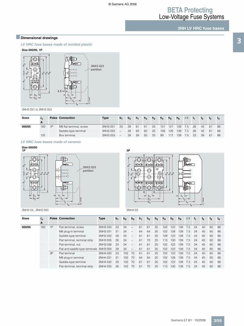
BETA ProtectingLow-Voltage Fuse Systems
3NH LV HRC fuse bases
3/55Siemens ET B1 · 10/2008
3
* You can order this quantity or a multiple thereof.
■ Dimensional drawings
LV HRC fuse bases made of molded plastic
LV HRC fuse bases made of ceramic
Size 000/00, 1P
3NH3 051 to 3NH3 053
Sizes In Poles Connection Type b1 b2 h1 h2 h3 h4 h5 h6 ∅ l t1 t2 t3 t4A
000/00 160 1P M8 flat terminal, screw 3NH3 051 23 39 61 61 25 101 121 139 7.5 26 42 61 86
Saddle-type terminal 3NH3 052 -- 39 60 60 25 108 120 139 7.5 26 42 61 86
125 Box terminal 3NH3 053 -- 39 59 50 25 99 117 139 7.5 23 39 61 86
h 4 h 5 h 6
h 1h 3
h 2
b2b1
t2t3
t1
t4
4,5
øl
3NX3 023 partition
I2_1
5447
Size 000/001P 3P
3NH3 03., 3NH3 050 3NH4 03.
Sizes In Poles Connection Type b1 b2 b3 h1 h2 h3 h4 h5 h6 ∅ l t1 t2 t3 t4A
000/00 160 1P Flat terminal, screw 3NH3 030 23 34 -- 61 61 25 102 122 139 7.5 24 40 60 86
M8 plug-in terminal 3NH3 031 31 34 -- 64 64 25 102 128 139 7.5 24 40 60 86
Saddle-type terminal 3NH3 032 29 34 -- 61 61 25 109 122 139 7.5 24 40 60 86
Flat terminal, terminal strip 3NH3 035 26 34 -- 61 70 25 113 130 139 7.5 24 40 60 86
Flat terminal, nut 3NH3 038 23 34 -- 61 61 25 102 122 139 7.5 24 40 60 86
Flat and saddle-type terminals 3NH3 050 29 34 -- 61 61 25 102 122 139 7.5 24 40 60 86
3P Flat terminal 3NH4 030 23 102 70 61 61 25 102 122 139 7.5 24 40 60 86
M8 plug-in terminal 3NH4 031 31 102 70 64 64 25 102 128 139 7.5 24 40 60 86
Saddle-type terminal 3NH4 032 29 102 70 61 61 25 102 122 139 7.5 24 40 60 86
Flat terminal, terminal strip 3NH4 035 26 102 70 61 70 25 113 130 139 7.5 24 40 60 86
t2t3
t1
t4
h 4 h 5 h 6
h 1h 3
h 2
b2b1
øl
3NX3 023partition
I2_1
5449
b2
b1
h 4 h 5 h 6
b3
h 1h 3
h 2
t2t3
t1
t4
øl
I2_1
5448
ET_B1_2009_en.book Seite 55 Freitag, 12. Dezember 2008 9:47 09
© Siemens AG 2008© Siemens AG 2008

BETA ProtectingLow-Voltage Fuse Systems
3NH LV HRC fuse bases
3/56 Siemens ET B1 · 10/2008
3
* You can order this quantity or a multiple thereof.
Size 0, 1P
3NH3 12.
Sizes In Poles Connection Type b1 b2 h1 h2 h3 h4 h5 h6 ∅ l t1 t2 t3 t4A
0 160 1P Flat terminal 3NH3 120 23 38 87 87 25 150 173 179 7.5 24 40 60 88
Plug-in terminal 3NH3 122 31 38 87 87 25 150 173 179 7.5 24 40 60 88
t2t3
t1
t4
h 4 h 5 h 6
h 1h 3
h 2
b2b1
øl
3NX2 030partition
I2_1
5450
Size 11P 3P
3NH3 2.0 3NH4 230
Sizes In Poles Connection Type b1 b2 b3 h1 h2 h3 h4 h5 h6 ∅ l t1 t2 t3 t4A
1 250 1P M10 flat terminal 3NH3 230 35 49 -- 101 101 25 177 202 203 10.5 35 55 84 107
Double busbar terminal 3NH3 220 35 49 -- 101 101 25 177 202 203 10.5 35 55 84 107
3P M10 flat terminal 3NH4 230 35 146 111 101 101 25 177 202 203 10.5 35 55 84 107
b2b1
h 4 h 5 h 6
b3
h 1h 3
h 2
t2t3
t1
t4
øl 3NX2 024partition
I2_1
5451
b2b1
h 4 h 5 h 6
h 1h 3
h 2
t2t3
t1
t4
b3
øl
I2_1
5452
ET_B1_2009_en.book Seite 56 Freitag, 12. Dezember 2008 9:47 09
© Siemens AG 2008© Siemens AG 2008

BETA ProtectingLow-Voltage Fuse Systems
3NH LV HRC fuse bases
3/57Siemens ET B1 · 10/2008
3
* You can order this quantity or a multiple thereof.
1) Size 4 LV HRC fuse links are also screwed onto the base.
Size 21P
Size 31P
3NH3 3.0 3NH3 4.0
Sizes In Poles Connection Type b1 b2 h1 h2 h3 h4 h5 h6 ∅ l t1 t2 t3 t4A
2 400 1P M10 flat terminal 3NH3 330 35 49 113 113 25 202 227 228 10.5 35 55 90 115
Double busbar terminal 3NH3 320 35 49 113 113 25 202 227 228 10.5 35 55 90 115
3 630 1P M12 flat terminal 3NH3 430 35 49 121 121 25 212 242 242 10.5 35 57 101 130
Double busbar terminal 3NH3 420 35 49 121 121 25 212 242 242 10.5 35 57 101 130
b2b1
h 4 h 5 h 6
b3
h 1h 3
h 2
t2t3
t1
t4
øl3NX2 025partition
I2_1
5453
b2b1
h 5 =
h6
h 4
b3
h 1h 3
h 2
øl
t2t3
t1
t4
3NX2 026partition
I2_1
5454
Size 4, 1P
3NH3 530
Sizes In Poles Connection Type b1 b2 b3 h1 h2 h3 h4 h5 ∅ l t1 t2 t3A
41) 1250 1P M12 flat terminal 3NH3 530 50 102 30 156 156 25 270 312 13 51 116 144
4a Can only be used in bases with swivel mechanism
øl
h 1h 3
b2b1
b3
h 5h 4
h 2
t2t3
t1
I2_1
5455
ET_B1_2009_en.book Seite 57 Freitag, 12. Dezember 2008 9:47 09
© Siemens AG 2008© Siemens AG 2008

BETA ProtectingLow-Voltage Fuse Systems
3NH LV HRC fuse bases
3/58 Siemens ET B1 · 10/2008
3
* You can order this quantity or a multiple thereof.
LV HRC bus-mounting bases1) LV HRC fuse bases with tandem design
1) LV HRC bus-mounting bases are only connected on one side using terminals, the second connection is made through the bottom of the base.
LV HRC fuse bases with swivel mechanism
Size 000/00, 160 A1P
Size 000/00, 80 A3P
3NH3 036, 3NH3 037 Busbar center-to-center clearance 40 mm 3NH4 037, 3NH4 045
91
4464
28
95 114
2937
22
3NX2 027 phase barrier
I2_1
5456
I2_0
6498
a33 33107
213,
5
4491
28
230
Sizes 000/00, 1, 3 and 4a
3NH7 03., 3NH7 23., 3NH7 33., 3NH7 520
Sizes In Type a b c d e l m n o
A
000/00 160 3NH7 030, 3NH7 031, 3NH7 032
44 149 45 88.5 22.5 120 17 18 200
1 250 3NH7 230, 3NH7 231, 3NH7 232
68 230 68 123.5 23 177 25 40 300
3 630 3NH7 330, 3NH7 331, 3NH7 332
90 270 96 153.5 15.5 220.5 30.5 35 350
4a 1250 3NH7 520 116 350 154.5 217.5 69 270 40 26 440
I2_1
1357
ao
d
eb
c
ln
m
ET_B1_2009_en.book Seite 58 Freitag, 12. Dezember 2008 9:47 09
© Siemens AG 2008© Siemens AG 2008
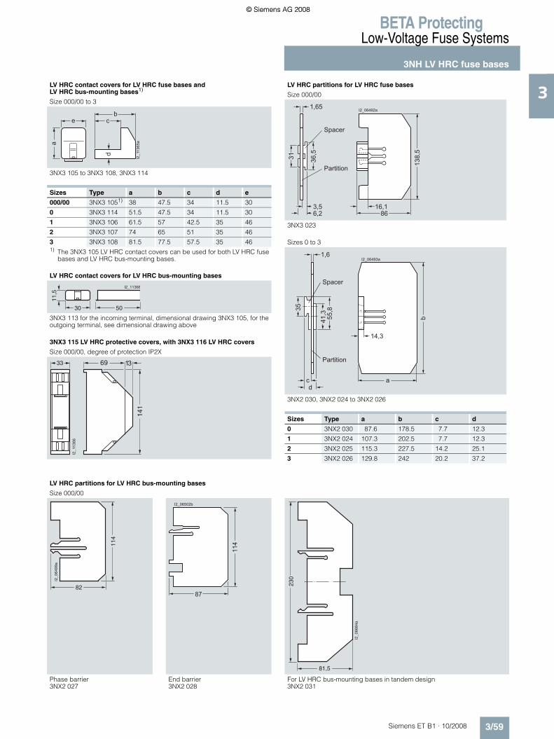
BETA ProtectingLow-Voltage Fuse Systems
3NH LV HRC fuse bases
3/59Siemens ET B1 · 10/2008
3
* You can order this quantity or a multiple thereof.
LV HRC contact covers for LV HRC fuse bases and LV HRC bus-mounting bases1)
Size 000/00 to 3
3NX3 105 to 3NX3 108, 3NX3 114
Sizes Type a b c d e
000/00 3NX3 1051) 38 47.5 34 11.5 30
0 3NX3 114 51.5 47.5 34 11.5 30
1 3NX3 106 61.5 57 42.5 35 46
2 3NX3 107 74 65 51 35 46
3 3NX3 108 81.5 77.5 57.5 35 461) The 3NX3 105 LV HRC contact covers can be used for both LV HRC fuse
bases and LV HRC bus-mounting bases.
LV HRC contact covers for LV HRC bus-mounting bases
3NX3 113 for the incoming terminal, dimensional drawing 3NX3 105, for the outgoing terminal, see dimensional drawing above
3NX3 115 LV HRC protective covers, with 3NX3 116 LV HRC covers
Size 000/00, degree of protection IP2X
I2_1
1365
a
cb
d
e
a
5030
I2_11368
11,5
�� �
���
��
����
��
LV HRC partitions for LV HRC fuse bases
Size 000/00
3NX3 023
Sizes 0 to 3
3NX2 030, 3NX2 024 to 3NX2 026
Sizes Type a b c d
0 3NX2 030 87.6 178.5 7.7 12.3
1 3NX2 024 107.3 202.5 7.7 12.3
2 3NX2 025 115.3 227.5 14.2 25.1
3 3NX2 026 129.8 242 20.2 37.2
138,
5
866,2
1,65
3,5 16,1
36,531
Spacer
Partition
I2_06492a
b
a
14,3
c
1,6
d
41,3 55,835
Spacer
Partition
I2_06493a
LV HRC partitions for LV HRC bus-mounting bases
Size 000/00
Phase barrier End barrier For LV HRC bus-mounting bases in tandem design3NX2 027 3NX2 028 3NX2 031
114
82
I2_0
6499
a
114
87
I2_06502b
230
81,5
I2_0
6684
a
ET_B1_2009_en.book Seite 59 Freitag, 12. Dezember 2008 9:47 09
© Siemens AG 2008© Siemens AG 2008

BETA ProtectingLow-Voltage Fuse Systems
3NH LV HRC fuse bases
3/60 Siemens ET B1 · 10/2008
3
* You can order this quantity or a multiple thereof.
Fuse pullers
Sizes 000 to 4
3NX1 013 (without sleeve), 3NX1 014 (with sleeve)
27,5
47,5
68 125
13024
66
136
350
92,526
I2_06503a
Sleeve
Isolating links with insulated grip lugs
Size 000/00 to 3
3NG1 .02
a e d
I2_06490
g
b
h
c3,5
13 6 f
Sizes Type a b c d e f g h
000/00 3NG1 002 44 15 48 78 54 20.5 8 19
0 3NG1 102 60.5 15 48 125 68 20.5 8 19
1 3NG1 202 61 20 53 135 72 23 9 24
2 3NG1 302 61 26 61 150 72 23 9 29
3 3NG1 402 61 32 73 150 72 23 9 36
Isolating links with non-insulated grip lugs
Size 4 Size 4a
3NG1 503 3NG1 505
I2_06511a
8
68200
30
150
16
61
32
5085
105
5085105
9
6 4053
,588 19
7
I2_06685a
ET_B1_2009_en.book Seite 60 Freitag, 12. Dezember 2008 9:47 09
© Siemens AG 2008© Siemens AG 2008

BETA ProtectingLow-Voltage Fuse Systems
3NH LV HRC fuse bases
3/61Siemens ET B1 · 10/2008
3
* You can order this quantity or a multiple thereof.
■ More information
Space requirements when installing LV HRC fuse bases
1) This measurement specifies the required overall mounting depth with base d and the overall mounting height h.
2) Placing an additional base on the barrier and plug-on part does not increase the distance, rather the bases lie flat directly on top of one another.
3) If the bases are installed directly on a side wall in the distribution board, one spacer part can be broken off. This would reduce the distance measurement.
1 LV HRC fuse base, 3P 3 LV HRC fuse bases, 1P LV HRC partition
Size Mounting width (mm) of LV HRC fuse bases Mounting height (mm)
Mounting depth (mm)
1 unit, 3P 3 units, 1P Distance through spacer
3NX2 0.. barriers with matching bases1)
Bases with phase barrier, without end barrier
Bases with phase barrier and 2 end barriers
Bases with phase barrier, without end barrier
Bases with phase barrier and 2 end barriers
h d
000/00 102 106 100 1042) 2 138 86
LV HRC bus-mounting bases see page 3/58 – 114 90
0 -- -- 128 142 7 178 90
1 163 177 158 172 7 202 110
2 -- -- 184 224 203) 227 118
3 -- -- 208 272 323) 242 132
4 Installation without barriers; for mounting see page 3/58 n/a
4a Can only be used in bases with swivel mechanism n/a
I2_1
1361
I2_1
1362
h
t
Spacer
Barrier
I2_1
1363
a
Space requirements when installing LV HRC bus-mounting basesSpace requirements for 3-piece, 1-pole 3NH3 036 and 3NH3 037 LV HRC bus-mounting bases, staggered
82
I2_1
1364
71
38
Sad
dle-
type
term
inal
con
nect
ion:
175
Ter
min
al s
trip
: 182
ET_B1_2009_en.book Seite 61 Freitag, 12. Dezember 2008 9:47 09
© Siemens AG 2008© Siemens AG 2008
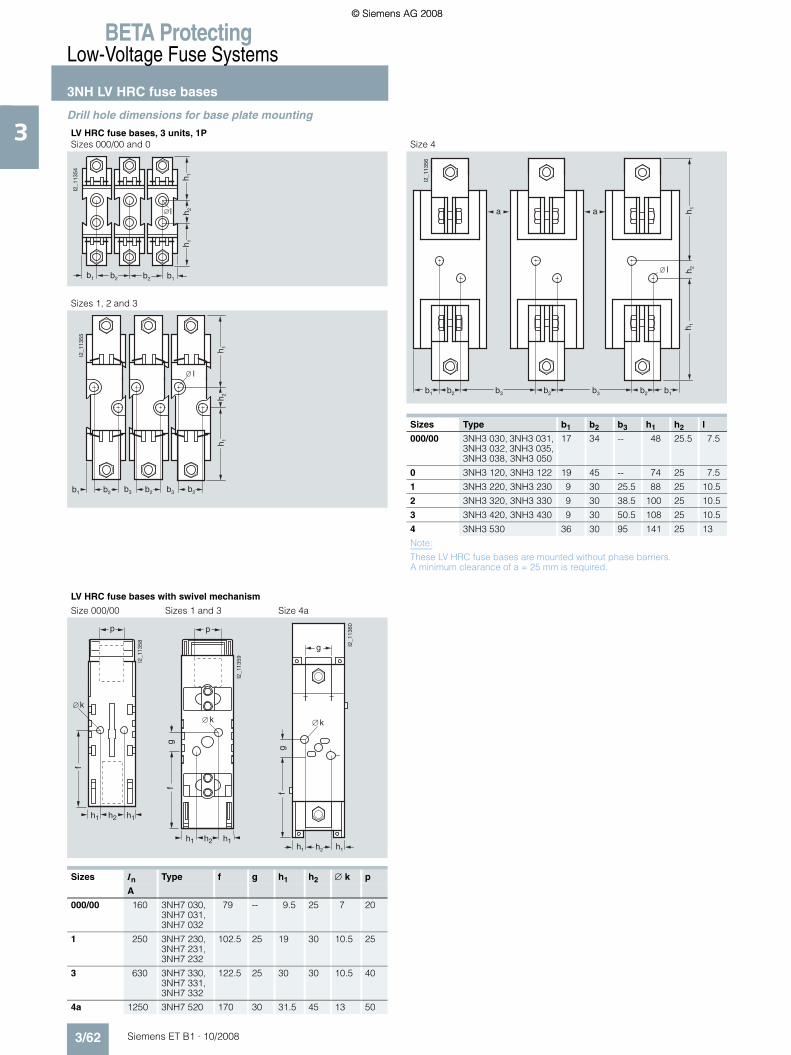
BETA ProtectingLow-Voltage Fuse Systems
3NH LV HRC fuse bases
3/62 Siemens ET B1 · 10/2008
3
* You can order this quantity or a multiple thereof.
Drill hole dimensions for base plate mounting
LV HRC fuse bases, 3 units, 1PSizes 000/00 and 0 Size 4
Sizes 1, 2 and 3
Sizes Type b1 b2 b3 h1 h2 l
000/00 3NH3 030, 3NH3 031, 3NH3 032, 3NH3 035, 3NH3 038, 3NH3 050
17 34 -- 48 25.5 7.5
0 3NH3 120, 3NH3 122 19 45 -- 74 25 7.5
1 3NH3 220, 3NH3 230 9 30 25.5 88 25 10.5
2 3NH3 320, 3NH3 330 9 30 38.5 100 25 10.5
3 3NH3 420, 3NH3 430 9 30 50.5 108 25 10.5
4 3NH3 530 36 30 95 141 25 13
Note:
These LV HRC fuse bases are mounted without phase barriers. A minimum clearance of a = 25 mm is required.
b1
h 1
I2_1
1354
h 2h 1
l
b2b2b1
b1
I2_1
1356
b2
h 1h 1
h 2
aa
b3 b2 b1b2b3
l
b3b2b3b2
h 1
b2
I2_1
1355
h 2h 1
b1
l
LV HRC fuse bases with swivel mechanism
Size 000/00 Sizes 1 and 3 Size 4a
����
���
�
�
���� ��
�
����
���
�
��
���� ��
�
h2
f
h1 h1
� k
g
I2_1
1360
g
Sizes In Type f g h1 h2 ∅ k p
A
000/00 160 3NH7 030, 3NH7 031, 3NH7 032
79 -- 9.5 25 7 20
1 250 3NH7 230, 3NH7 231, 3NH7 232
102.5 25 19 30 10.5 25
3 630 3NH7 330, 3NH7 331, 3NH7 332
122.5 25 30 30 10.5 40
4a 1250 3NH7 520 170 30 31.5 45 13 50
ET_B1_2009_en.book Seite 62 Freitag, 12. Dezember 2008 9:47 09
© Siemens AG 2008© Siemens AG 2008

BETA ProtectingLow-Voltage Fuse Systems
3NP LV HRC fuse switch disconnectors
3/63Siemens ET B1 · 10/2008
3
* You can order this quantity or a multiple thereof.
■ Overview
SENTRON 3NP4 and 3NP5 fuse switch disconnectors are switching devices for the occasional manual switching/isolating of loads and distribution boards. They are able to switch on,lead and switch off the specified rated current (including a spe-cific overload).
With the SENTRON 3NP4 and 3NP5 fuse switch disconnectors, all poles of downstream electric loads can be safely disconnected from the system under load.
The SENTRON 3NP4 and 3NP5 fuse switch disconnectors are ideal for surface mounting and installation on and in distribution boards (e.g. ALPHA, SIKUS), meter cabinets (e.g. ALPHA 400-ZS) and molded-plastic distribution systems, such as 8HP.
The ability to mount them on a range of different busbar systems allows their very diverse implementation in control cabinet and control engineering.
The sizes SENTRON 3NP4 LV HRC 0001) and LV HRC 00 can be snapped onto 35 mm standard mounting rails and are ideal for combining with other switching devices e.g. in capacitor modules for p.f. compensation.
The SENTRON 3NP4 and 3NP5 fuse switch disconnectors are used in conjunction with SITOR semiconductor fuses for the effective protection of frequency converters and soft starters (see chapter "SITOR semiconductor fuses").
1) Corresponds to the fuse size LV HRC 000 according to IEC 60269-2.
■ Benefits
• The SENTRON 3NP4 and 3NP5 fuse switch disconnectors comprise a base and a removable fuse carrier with view and measuring window. The fuse links can be replaced without tools. This considerably facilitates installation
• The three conducting paths in the base and the fuse links in the fuse carrier are separated by partitions that overlap when opening and closing the device. This type of failsafe protection is called "complete compartmentalization" and effectively prevents phase arcing.
• SENTRON 3NP5 fuse switch disconnectors are also equipped with locating springs, which are fitted to the side of the base. These enable the "high speed closing" of devices, regardless of the actuation speed of the operator.
• The SENTRON 3NP4 and 3NP5 fuse switch disconnectors are used with LV HRC fuse links of sizes LV HRC 000 to LV HRC 3 according to IEC 60269-2 and DIN VDE 43620. SITOR semi-conductor fuses can continue to be used for a wide range of applications.
• With its LV HRC fuse links, size 000 with a rated current of 125 and 160 A, Siemens offers an extremely compact solution.
ET_B1_2009_en.book Seite 63 Freitag, 12. Dezember 2008 9:47 09
© Siemens AG 2008© Siemens AG 2008

BETA ProtectingLow-Voltage Fuse Systems
3NP LV HRC fuse switch disconnectors
3/64 Siemens ET B1 · 10/2008
3
* You can order this quantity or a multiple thereof.
■ Technical specifications
1) 125/160 A only with 3NY1 236 feeder terminals and 21 mm wide 3NY1 822 (125 A) and 3NY1 824 (160 A) fuse links; see page 3/76.
2) When switching without load (AC-20 B, DC-20 B), direct voltages up to 690 V DC can be applied. For degree of pollution 2, the disconnectors can be used up to 1000 V AC-20 B, DC-20 B (switching without load). Conducting paths in series: 3 for 3NP40; 2 for 3NP42, 3NP43 and 3NP44.
3NP40 1 3NP40 7 3NP42 7 3NP43 7 3NP44 7
Standards IEC 60947-1; IEC 60947-3; VDE 0660-107Approved acc. to UL508
Rated uninterrupted current Iu A 1601) 160 250 400 630For fuse links acc. to DIN 43620 Size 00C/000 00 1 and 0 2 and 1 3 and 2
Conventional thermal current Ith A 1601) 160 250 400 630
Rated operational voltage Ue50 Hz/60 Hz V AC 690 690
V DC 220 (3 conducting paths series-connected)
440 (2 conducting paths series-connected)
Rated insulation voltage Ui V 690 800For safety monitoring max. 690 V.
Rated impulse withstand voltage Uimp kV 6
Rated conditional short-circuit current with fuses (by fast switch on)
With fuse links Rated current Size/A 000/100 (35) 00/160 1/250 2/400 3/630At 400 V AC (690 V) kA
(r.m.s. value)50 (50) 50 50 50 50
Maximum permissible let-through I2t value kA2s 56 (7.8) 158 551 1515 4340
Permissible let-through current of the fuse kA (peak value)
11 (5) 15 25 35 55
Short-circuit strength with fuses(with closed disconnector)
With fuse linksRated current Size/A 000/100 00/160 1/250 2/400 3/630At 690 V kA
(r.m.s. value)100 50 50 50 50
Permissible let-through current of the fuse kA (peak value)
15 15 25 35 55
Rated making and breaking capacity (infeed from top or bottom)
At 400 V AC, with fuse links or isolating links Size 000 00 1 2 3Rated breaking current Ic (p.f. = 0.35) A
(r.m.s. value)800 (p.f. = 0.45)
800 2000 3200 5040
Rated operational current Ie at AC-21B, AC-22B A 160 160 250 400 630AC-23B A 100 100 250 400 630
At 500 V AC, with fuse links or isolating links
Size 000 00 1 2 3
Rated breaking current Ic (p.f. = 0.35) A (r.m.s. value)
320 (p.f. = 0.45)
320 750 1200 1890
Rated operational current Ie at AC-21B A 160 160 250 400 630AC-22B A 100 100 250 400 630AC-23B A 40 40 -- -- --
At 690 V AC, with fuse links or isolating links
Size 000 00 1 2 3
Rated breaking current Ic (p.f. = 0.35) A 200/240 200/240 375 600 945(r.m.s. value) (at p.f. =
0.45/0.95)(at p.f. = 0.45/0.95)
Rated operational current Ie at AC-21B A 160 160 250 400 630AC-22B A 50 50 -- -- --AC-23B A 25 25 -- -- --
At 220/240 V DC, with fuse links2) or isolating links
Size 000 00 1 2 3
Rated operational current Ie at 220 V DC-23B/DC-21B A 80/160 80/160 -- -- --440 V DC-21B A -- -- 250 400 630
ET_B1_2009_en.book Seite 64 Freitag, 12. Dezember 2008 9:47 09
© Siemens AG 2008© Siemens AG 2008

BETA ProtectingLow-Voltage Fuse Systems
3NP LV HRC fuse switch disconnectors
3/65Siemens ET B1 · 10/2008
3
* You can order this quantity or a multiple thereof.
1) Only with isolating links; otherwise, please observe specifications of fuse manufacturer.
1) Implementation up to Ui = 1000 V is also possible if maintaining degree of pollution 2 (instead of 3).
3NP40 1 3NP40 7 3NP42 7 3NP43 7 3NP44 7
Capacitor switching capacity
At 400 V ACCapacitor rating kvar 50 50 -- -- --Rated current In A 72 72 -- -- --
At 525 V ACCapacitor rating kvar 50 50 -- -- --Rated current In A 55 55 -- -- --
Permissible ambient temperature °C -25 ... +551) for operation -50 ... +80 for storage
Mechanical service life Operating cycles
2000 2000 1600 1000 1000
Degree of protection (operator side)
Without molded-plastic cover/cable lug cover IP00 (3NP40 with box terminal and properly connected conductors: IP20)
With molded-plastic cover/cable lug cover IP30 (switch closed), IP20 (switch open)
Power loss of switch at Ith (plus power dissipation of fuse links)
Without busbar adapter W 4.5 (at 100 A) 10 15 30 47
with busbar adapter W 8.5 (at 100 A) 20 47 83 127
Main conductor connections
Flat terminal for cable lug acc. to DIN 46234, mm2 -- Up to 2 × 70 Up to 150 Up to 240 Up to 2 × 240Max. conductor cross-section (stranded) (M8) (M10) (M10) (M12)
Box terminal/terminal (finely stranded, with end sleeve)
mm2 1.5 ... 50 (35) 2.5 ... 70 (50) 70 ... 150 120 ... 240 150 ... 300
Busbars (width × thickness) mm × mm -- 22 × 5 22 ... 30 × 22 ... 30 × 25 ... 40 × 5 ... 10 5 ... 10 5 ... 10
Laminated Cu strips, non-perforated in terminals (width × thickness)
mm × mm 8 × 8 Up to 9 × 8 Up to 16 × 8 Up to 20 × 10 Up to 24 × 10
Tightening torques for terminal screws
For flat terminals Nm -- 10 ... 12 30 ... 35 30 ... 35 35 ... 40
With SIGUT box terminal/terminal Nm 3 ... 3.5 8 ... 10 6 8 8
Auxiliary switch 1 CO (accessories)
3NY3 035 50 Hz/60 Hz to 230 V AC rated operational current Ie at AC-14 A 0.25 (Ith = 5 A), at 24 V DC: Ie = 0.45 A; flat termination according to DIN 46244:
A 2.8 × 0.5
3NY3 030 50 Hz/60 Hz to 230 V AC Rated operational current Ie at AC-13 A 0.1 (Ith = 0.1 A); quick-connect terminal according to DIN 46245: A 2.8 ... 1
Permissible mounting positions Vertical or horizontal installation (no reduction of specified switching capacity)
3NP50 3NP52 3NP53 3NP54
Standards IEC 60947-1, IEC 60947-3, VDE 0660-107Approved acc. to UL508
Rated uninterrupted current Iu A 160 250 400 630 For fuse links acc. to DIN 43620 Size 00 1 and 0 2 and 1 3 and 2(if using semiconductor protection fuse links, the rated current must be reduced – see catalog"Configuring SITOR", Order No. E20001-A700-P302)
Conventional free air thermal current Ith A 160 250 400 630
Rated operational voltage Ue50 Hz/60 Hz V AC 690 V DC 440 (3 conducting paths in series),
220 (2 conducting paths in series and for fuse monitoring through 3RV)
Rated insulation voltage Ui V 6901)
Rated impulse withstand voltage Uimp kV 6
Rated conditional short-circuit current with fuses (by fast switch on)
With fuse linksRated current Size/A 00/160 1/250 2/400 3/630At 500 V AC kA
(r.m.s. value)50 50 50 50
Permissible let-through current of the fuses kA (peak value)
15 25 40 50
ET_B1_2009_en.book Seite 65 Freitag, 12. Dezember 2008 9:47 09
© Siemens AG 2008© Siemens AG 2008

BETA ProtectingLow-Voltage Fuse Systems
3NP LV HRC fuse switch disconnectors
3/66 Siemens ET B1 · 10/2008
3
* You can order this quantity or a multiple thereof.
1) Rated making and breaking current according to IEC 60947-3 rated making current I = 10 × Ie (AC-23); 3 × Ie (AC-22); 1.5 × Ie (AC-21) rated breaking current I = 8 × Ie (AC-23); 3 × Ie (AC-22); 1.5 × Ie (AC-21).
2) When electronic fuse monitors are used, infeed must be from the top.3) Insert silver-plated isolating links.
3NP50 3NP52 3NP53 3NP54
Short-circuit strength with fuses (with closed disconnector)With fuse linksRated current Size/A 00/160 1/250 2/400 3/630At 500 V AC kA
(r.m.s. value)100 100 50 50
Maximum permissible let-through I2t value kA2s 223 780 2150 5400
Permissible let-through current of the fuses kA (peak value)
23 32 40 60
Rated short-circuit making capacityWith isolating links1) Size 00 1 2 3At 500 V AC kA
(peak value)6 17 17 17
Rated making and breaking capacity1)
(infeed from top or bottom)2)
Size 00 1 0 2 1 3 2
At 400 V AC, with fuse linksBreaking current Ic (p.f. = 0.35) A
(r.m.s. value)1600 2500 1600 4000 2500 5040 4000
Rated operational current Ie for AC-21B, AC-22B, AC-23B
A 160 250 160 400 250 630 400
At 500 V AC, with fuse linksBreaking current Ic (p.f. = 0.35) A
(r.m.s. value)1300 2500 1600 4000 2500 5040 4000
Rated operational current Ie for AC-21B, AC-22B, AC-23B
A 160 250 160 400 250 630 400
At 690 V AC, with fuse linksBreaking current Ic (p.f. = 0.35) A
(r.m.s. value)800 1280 1000 2520 1600 3200 2520
Rated operational current Ie at AC-21B, AC-22B A 160 250 160 400 250 630 400AC-23B A 100 160 125 315 200 400 315
At 220 (440) V DC, with 2 (3) conducting paths in series and fuse linksBreaking current Ic (L/R = 15 ms) A 640 1000 640 1600 1600 2520 1600Rated operational current Ie for DC-23B A 160 250 160 250 250 630 400
Switching capacity with isolating links3)
(infeed from top or bottom)
At 400 V AC, with isolating links Size 00 1 2 3Breaking current Ic (p.f. = 0.35) A
(r.m.s. value)1600 2500 2500 4000
Rated operational current Ie at AC-21B, AC-22B A 160 250 400 630AC-23B A 160 250 315 500
At 500 V AC, with isolating linksBreaking current Ic (p.f. = 0.35) A
(r.m.s. value)1300 2500 2500 4000
Rated operational current Ie at AC-21B, AC-22B A 160 250 400 630AC-23B A 160 250 315 500
At 690 V AC, with isolating linksBreaking current Ic (p.f. = 0.35) A
(r.m.s. value)800 1280 1600 2520
Rated operational current Ie at AC-21B, AC-22B A 160 250 400 630AC-23B A 100 160 200 315
At 220 V DC, with isolating linksBreaking current Ic (L/R = 15 ms) A 640 1000 1600 1600Rated operational current Ie for DC-23B A 160 200 400 400
Switching capacity for horizontal installation Up to 690 V AC-22B
No reduction of the specified switching capacity (values for AC-23B to 690 V on request)
ET_B1_2009_en.book Seite 66 Freitag, 12. Dezember 2008 9:47 09
© Siemens AG 2008© Siemens AG 2008

BETA ProtectingLow-Voltage Fuse Systems
3NP LV HRC fuse switch disconnectors
3/67Siemens ET B1 · 10/2008
3
* You can order this quantity or a multiple thereof.
1) When using isolating links. If using fuse links, please observe specifications of fuse manufacturer.
2) For 3NP52 with clamp terminal, degree of protection IP10. 3) With busbar adapter.
3NP50 3NP52 3NP53 3NP54
Capacitor switching capacity
At 400 V ACCapacitor rating kvar 80 90 150 250Rated current In A 116 130 216 361
At 525 V ACCapacitor rating kvar 100 125 200 300Rated current In A 110 137 220 330
Permissible ambient temperature °C -25 ... +55 for operation1) -50 ... +80 for storage
Mechanical service life Operating cycles
1600
Degree of protection
Without molded-plastic cover IP002)
With molded-plastic cover andclosed fuse carrier on the operator side IP30With open fuse carrier IP10
Power loss of switches at Ith(plus power loss of the fuse links) without busbar adapter
W 7.8 (16.33)) 7.5 15 39
Main conductor connections
Cable lug, max. conductor cross-section (stranded) mm2 2.5 ... 120 6 ... 150 6 ... 240 6 ... 2 × 240Busbars mm 16 ... 22 22 ... 30 22 ... 30 22 ... 30Clamp terminal mm2 2.5 ... 50 35 ... 120 -- --
Tightening torques
With cable lugs Nm 18 ... 22 25 ... 30 25 ... 30 25 ... 30With busbars Nm 18 ... 22 25 ... 30 25 ... 30 25 ... 30With clamp terminal Nm 9 ... 11 5 ... 6 -- --
Terminal screws
With cable lugs M8 M10 M10 M10With busbars M8 M10 M10 M10With clamp terminal M8 2 × M6 -- --
PE/ground terminal
Cable lug acc. to DIN 46234 mm2 -- 2.5 ... 70 6 ... 2 × 70 6 ... 2 × 120Busbars mm -- 25 25 30Terminal screws -- M8 M10 M10
Auxiliary switch 1 NO + 1 NC (accessories) (the same voltage potential must be applied to both NO and NC contact)
At 50 Hz/60 Hz to 400 V AC, Rated operational current Ie at AC-12/AC-15
A 16/6
Flat plug-in terminal (DIN 46244) mm × mm 6.3 × 0.8
Permissible mounting positions Vertical or horizontal installation (switching capacity is sometimes reduced with horizontal installation)
Fuse monitors with 3RV motor starter protectors See motor starter protectors in Catalog LV 1.
Electronic fuse monitoring
Rated voltage AC 50 Hz/60 Hz V 400 -15 % ... 500 +10 %, self-powered (infeed from above)
Max. starting current A 20Continuous current A 5Breaking current A 5
Switching capacity VA 1000
Short-circuit strength (1 ms) A 100Response time s < 1Temperature range (operation) °C -10 ... +75Plug-in connectors/connections 6P
Minimum potential difference required between top and bottom connections of the switch (e.g. for use in meshed networks)
V >10
Signal contact for electronic fuse monitoring 2 NO + 1 NC
Rated operational current IeAt 250 V, DC-13 A 0.27At 240 V, AC-15 A 1.5
Rated free air thermal current Ith A 5
ET_B1_2009_en.book Seite 67 Freitag, 12. Dezember 2008 9:47 09
© Siemens AG 2008© Siemens AG 2008

BETA ProtectingLow-Voltage Fuse Systems
3NP LV HRC fuse switch disconnectors
3/68 Siemens ET B1 · 10/2008
3
* You can order this quantity or a multiple thereof.
■ Selection and ordering data
All fuse switch disconnectors with flat terminals must be used with the appropriate cable lug covers (3NY7 101 to 3NY7 141) for finger-safe cover according to BGV A2, see page 3/76.1) See LV HRC Fuse Links.2) Insert silver-plated isolating links.3) 125/160 A only possible with 21-mm wide 3NY1 822 (125 A) and 3NY1 824
(160 A) LV HRC fuse links, see page 3/77.
4) Corresponds to LV HRC fuse link size 00 with maximum width 21 mm (according to IEC 60269-2-1 and DIN 43620).
5) Can only be mounted on 5 mm thick busbars, a busbar thickness compensator is required for 3NP42 and 3NP43; see page 3/77. 3NP44 can only be mounted on busbars with a thickness of 10 mm!
Rated residual current
Connection type (double-ended)
For LV HRC fuse links acc. to DIN 436201)
For isolating links2)
Degree of protection IP00, without fuse links, without isolating links, with terminal screws
Iu Connection For conductor cross-section
DT Order No. Priceper PU
PG PU PS*/P. unit
Weightper PU approx.
A mm2 Size Size Unit(s) Unit(s) kg
Up to 160 A, also clip-on for standard mounting rail
1603) Box terminals
1.5 ... 50 0004) 00 } 3NP40 10-0CH01 103 1 1 0.512
160 Flatterminals
Up to 2 × 70 (M8)
00 a. 000 00 } 3NP40 70-0CA01 103 1 1 0.749
Boxterminals
2.5 ... 70 or 2 × 2.5 ... 16
} 3NP40 70-0CH01 103 1 1 0.800
250 Flat terminals
Up to 150 (M10)
1 and 0 1 and 0 } 3NP42 70-0CA01 103 1 1 2.436
400 Up to 240 (M10)
2 and 1 2 and 1 } 3NP43 70-0CA01 103 1 1 3.614
630 Up to 2 × 240 (M12)
3 and 2 3 and 2 } 3NP44 70-0CA01 103 1 1 4.984
For 40 mm busbar system
For busbars of width 12 mm or 15 mm and thickness 5 mm or 10 mm5)
With adapter, deep, e.g. for installation in ALPHA meter cabinets (ALPHA 400-ZS) and ALPHA distribution boards
3NP40 15-0CK01
1603) Box terminals
1.5 ... 50
Connec-tion, top
0004) 00 A 3NP40 15-0CK01 103 1 1 0.952
Connection, bottom
A 3NP40 15-0CJ01 103 1 1 0.970
160 Flat terminals
Up to 2 × 70 (M8)
Connec-tion, top
00 a. 000 00 A 3NP40 75-0CE01 103 1 1 1.210
Connection, bottom
A 3NP40 75-0CF01 103 1 1 1.244
Box terminals
2.5 ... 70 or 2 × 2.5 ... 16Connec-tion, top
00 a. 000 00 A 3NP40 75-0CK01 103 1 1 1.290
Connection, bottom
A 3NP40 75-0CJ01 103 1 1 1.274
ET_B1_2009_en.book Seite 68 Freitag, 12. Dezember 2008 9:47 09
© Siemens AG 2008© Siemens AG 2008

BETA ProtectingLow-Voltage Fuse Systems
3NP LV HRC fuse switch disconnectors
3/69Siemens ET B1 · 10/2008
3
* You can order this quantity or a multiple thereof.
All fuse switch disconnectors with flat terminals must be used with the appropriate cable lug covers (3NY7 101 to 3NY7 141) for finger-safe cover according to BGV A2, see page 3/76.1) See LV HRC Fuse Links.2) Insert silver-plated isolating links.3) Can only be mounted on 5 mm thick busbars, a busbar thickness compensator
is required for 3NP42 and 3NP43; see page 3/77. 3NP44 can only be mounted on busbars with a thickness of 10 mm!
4) 125/160 A only possible with 21 mm 3NY1 822 (125 A) and 3NY1 824 (160 A) LV HRC fuse links, see page 3/77.
5) Corresponds to LV HRC fuse link size 00 with maximum width 21 mm (according to IEC 60269-2-1 and DIN 43620).
6) No further cover required for 3NP40 with box terminal.
Rated residual current
Connection type (double-ended)
For LV HRC fuse links acc. to DIN 436201)
For isolating links2)
Degree of protection IP00, without fuse links, without isolating links, with terminal screws
Iu Connection For conductor cross-section
DT Order No. Priceper PU
PG PU PS*/P. unit
Weightper PU approx.
A mm2 Size Size Unit(s) Unit(s) kg
For 40 mm busbar system
For busbars of width 12 mm or 15 mm and thickness 5 mm or 10 mm3)
With flat adapter according to DIN 43620 -6, for ALPHA distribution boards (STAB/SIKUS)
1604) Boxterminals
1.5 ... 50
Connection, top
0005) 00 A 3NP40 15-1CK01 103 1 1 0.892
Connection, bottom
B 3NP40 15-1CJ01 103 1 1 0.888
160 Flat terminals
Up to 2 × 70 (M8)
Connection, top
00 a. 000 00 a. 000 A 3NP40 75-1CE01 103 1 1 1.186
Connection, bottom
A 3NP40 75-1CF01 103 1 1 1.189
Boxterminals
2.5 ... 70 or 2 × 2.5 ... 16Connection, top
00 a. 000 00 a. 000 A 3NP40 75-1CK01 103 1 1 1.261
Connection, bottom
A 3NP40 75-1CJ01 103 1 1 1.213
250 Flat terminals
Up to 240 (M10)
Connection, top or bottom
1 and 0 1 and 0 A 3NP42 75-1CG01 103 1 1 3.719
For 60 mm busbar system
For busbars of width 12 mm or 30 mm and thickness 5 mm or 10 mm3)
As flat, T and I profiles, as well as Rittal PLS systems
1604) Box terminals6)
1.5 ... 50
Connection, top
0003) 00 A 3NP40 16-1CK01 103 1 1 0.916
Connection, bottom
} 3NP40 16-1CJ01 103 1 1 0.950
ET_B1_2009_en.book Seite 69 Freitag, 12. Dezember 2008 9:47 09
© Siemens AG 2008© Siemens AG 2008

BETA ProtectingLow-Voltage Fuse Systems
3NP LV HRC fuse switch disconnectors
3/70 Siemens ET B1 · 10/2008
3
* You can order this quantity or a multiple thereof.
All fuse switch disconnectors with flat terminals must be used with the appropriate cable lug covers (3NY7 101 to 3NY7 141) for finger-safe cover according to BGV A2, see page 3/76.1) See LV HRC Fuse Links.2) Insert silver-plated isolating links.3) Can only be mounted on 5 mm thick busbars, a busbar thickness compensator
is required for 3NP42 and 3NP43; see page 3/77. 3NP44 can only be mounted on busbars with a thickness of 10 mm!
4) No further cover required for 3NP40 with box terminal.5) SIRIUS motor starter protector with auxiliary switch 1 NO + 1 NC as stan-
dard. 3NP40 7 also available with auxiliary switch 2 NOs or 2 NCs on request.
6) For 3NP40 7 with output socket for auxiliary switch, the signal lead must be ordered separately, see page 3/77. In the case of 3NP41 to 3NP44, the auxiliary switch must be connected over a 2.8 mm × 0.5 mm flat terminal according to DIN 46244-A.
Rated residual current
Connection type (double-ended)
For LV HRC fuse links acc. to DIN 436201)
For isolating links2)
Degree of protection IP00, without fuse links, without isolating links, with terminal screws
Iu Connection For conductorcross-section
DT Order No. Priceper PU
PG PU PS*/P. unit
Weightper PU approx.
A mm2 Size Size Unit(s) Unit(s) kg
For 60 mm busbar system
For busbars of width 12 mm or 30 mm and thickness 5 mm or 10 mm3)
As flat, T and I profiles, as well as Rittal PLS systems
160 Flat terminals Up to 2 × 70 (M8)Connection, top
00 a. 000 00 A 3NP40 76-1CE01 103 1 1 1.203
Connection, bottom
} 3NP40 76-1CF01 103 1 1 1.201
Box terminals4)
2.5 ... 70 or 2 × 2.5 ... 16Connection, top
00 a. 000 00 B 3NP40 76-1CK01 103 1 1 1.295
Connection, bottom
} 3NP40 76-1CJ01 103 1 1 1.249
250 Flatterminals
Up to 150 (M10)
Connection, top or bottom
1 and 0 1 and 0 } 3NP42 76-1CG01 103 1 1 3.713
400 Flatterminals
Up to 240 (M10)
Connection, top or bottom
2 and 1 2 and 1 } 3NP43 76-1CG01 103 1 1 5.440
630 Flat terminals
Up to 2 × 240 (M12)
Connection, top or bottom
3 and 2 3 and 2 } 3NP44 76-1CG01 103 1 1 7.688
Surface mounting and installation
With fuse monitoring by SIRIUS motor starter protector5) 6)
Up to 160 A, also clip-on for standard mounting rail
160 Flat terminals Up to 2 × 70 (M8)
00 a. 000 00 A 3NP40 70-0FA01 103 1 1 1.276
Box terminals 2.5 ... 70 or 2 × 2.5 ... 16
A 3NP40 70-0FH01 103 1 1 1.350
250 Flat terminals Up to 150 (M10)
1 and 0 1 and 0 A 3NP42 70-0FA01 103 1 1 2.940
400 Flat terminals Up to 240 (M10)
2 and 1 2 and 1 A 3NP43 70-0FA01 103 1 1 4.174
630 Flat terminals Up to 2 × 240 (M12)
3 and 2 3 and 2 A 3NP44 70-0FA01 103 1 1 5.495
ET_B1_2009_en.book Seite 70 Freitag, 12. Dezember 2008 9:47 09
© Siemens AG 2008© Siemens AG 2008

BETA ProtectingLow-Voltage Fuse Systems
3NP LV HRC fuse switch disconnectors
3/71Siemens ET B1 · 10/2008
3
* You can order this quantity or a multiple thereof.
All fuse switch disconnectors with flat terminals must be used with the appropriate cable lug covers (3NY7 101 to 3NY7 141) for finger-safe cover according to BGV A2, see page 3/76.1) See LV HRC Fuse Links.2) Insert silver-plated isolating links.3) Can only be mounted on 5 mm thick busbars, a busbar thickness compensator
is required for 3NP42 and 3NP43; see page 3/77. 3NP44 can only be mounted on busbars with a thickness of 10 mm!
4) SIRIUS motor starter protectors, as standard with auxiliary switches1 NO + 1 NC. See Catalog LV 1
5) For 3NP40 7 with output socket for auxiliary switch, the signal lead must be ordered separately, see page 3/77. In the case of 3NP41 to 3NP44, the auxiliary switch must be connected over a 2.8 mm × 0.5 mm flat terminal according to DIN 46244-A.
Rated residual current
Connection type (double-ended)
For LV HRC fuse links acc. to DIN 436201)
For isolating links2)
Degree of protection IP00, without fuse links, without isolating links, with terminal screws
Iu Connection For conductor cross-section
DT Order No. Priceper PU
PG PU PS*/P. unit
Weightper PU approx.
A mm2 Size Size Unit(s) Unit(s) kg
For 40 mm busbar system
For busbars of width 12 mm or 15 mm and thickness 5 mm or 10 mm3)
With fuse monitoring by SIRIUS motor starter protector4)5)
With deep adapter, e.g. for installation in ALPHA meter cabinets and ALPHA distribution boards (STAB/SIKUS)
160 Flat terminals Up to 2 × 70(M8)Connection, top
00 a. 000 00 a. 000 B 3NP40 75-0FE01 103 1 1 1.812
Connection, bottom
B 3NP40 75-0FF01 103 1 1 1.780
Box terminals 2.5 ... 70 or 2 × 2.5 ... 16Connection, top
00 a. 000 00 a. 000 B 3NP40 75-0FK01 103 1 1 1.820
Connection, bottom
B 3NP40 75-0FJ01 103 1 1 1.831
With flat adapter according to DIN 43620 -6, for ALPHA distribution boards (STAB/SIKUS)
160 Flat terminals Up to 2 × 70 (M8)Connection, top
00 a. 000 00 a. 000 B 3NP40 75-1FE01 103 1 1 1.616
Connection, bottom
B 3NP40 75-1FF01 103 1 1 1.620
Box terminals 2.5 ... 70 or 2 × 2.5 ... 16Connection, top
00 a. 000 00 a. 000 B 3NP40 75-1FK01 103 1 1 1.717
Connec-tion, bottom
B 3NP40 75-1FJ01 103 1 1 1.630
250 Flat terminals Up to 240 (M10)Connection, top orbottom
1 and 0 1 and 0 A 3NP42 75-1FG01 103 1 1 4.210
ET_B1_2009_en.book Seite 71 Freitag, 12. Dezember 2008 9:47 09
© Siemens AG 2008© Siemens AG 2008

BETA ProtectingLow-Voltage Fuse Systems
3NP LV HRC fuse switch disconnectors
3/72 Siemens ET B1 · 10/2008
3
* You can order this quantity or a multiple thereof.
All fuse switch disconnectors with flat terminals must be used with the appropriate cable lug covers (3NY7 101 to 3NY7 141) for finger-safe cover according to BGV A2, see page 3/76.1) See LV HRC Fuse Links.2) Insert silver-plated isolating links.3) Can only be mounted on 5 mm thick busbars, a busbar thickness compensator
is required for 3NP42 and 3NP43; see page 3/77. 3NP44 can only be mounted on busbars with a thickness of 10 mm!
4) SIRIUS motor starter protectors, as standard with auxiliary switches 1 NO + 1 NC. See Catalog LV 1
5) For 3NP40 7 with output socket for auxiliary switch, the signal lead must be ordered separately, see page 3/77. In the case of 3NP41 to 3NP44, the auxiliary switch must be connected over a 2.8 mm × 0.5 mm flat terminal according to DIN 46244-A.
Rated residual current
Connection type (double-ended)
For LV HRC fuse links acc. to DIN 436201)
For isolating links2)
Degree of protection IP00, without fuse links, without isolating links, with terminal screws
Iu Connection Forconductor cross-section
DT Order No. Priceper PU
PG PU PS*/P. unit
Weightper PU approx.
A mm2 Size Size Unit(s) Unit(s) kg
For 60 mm busbar system
For busbars of width 12 mm or 15 mm and thickness 5 mm or 10 mm3)
Flat, T and I profiles, as well as on Rittal PLS systems
With fuse monitoring by SIRIUS motor starter protector4)5)
160 Flat terminals Up to 2 × 70(M8)Connection, top
00 and 000 00 B 3NP40 76-1FE01 103 1 1 1.670
Connection, bottom
A 3NP40 76-1FF01 103 1 1 1.890
Box terminals 2.5 ... 70 or 2 × 2.5 ... 16Connection, top
00 and 000 00 B 3NP40 76-1FK01 103 1 1 1.755
Connection, bottom
B 3NP40 76-1FJ01 103 1 1 1.915
250 Flat terminals Up to 150 (M10)Connection, top or bottom
1 and 0 1 and 0 A 3NP42 76-1FG01 103 1 1 4.171
400 Flat terminals Up to 240 (M10)Connection, top or bottom
2 and 1 2 and 1 A 3NP43 76-1FG01 103 1 1 5.845
630 Flat terminals Up to 2 × 240(M12)Connection, top or bottom
3 and 2 3 and 2 A 3NP44 76-1FG01 103 1 1 8.235
ET_B1_2009_en.book Seite 72 Freitag, 12. Dezember 2008 9:47 09
© Siemens AG 2008© Siemens AG 2008

BETA ProtectingLow-Voltage Fuse Systems
3NP LV HRC fuse switch disconnectors
3/73Siemens ET B1 · 10/2008
3
* You can order this quantity or a multiple thereof.
1) See LV HRC Fuse Links.2) The relevant 3NY1 106 cable lug covers must be used for 3NP50 60 with
flat terminals (see Accessories) for the purpose of protection against accidental contact according to DIN VDE 0106-100 (see page 3/76).
3) According to DIN 46234 or 16 mm2 ... 95 mm2 according to DIN 46235 (use M10 cable lug if necessary).
4) If auxiliary switch is retrofitted, additional drill holes are required on the switch.5) According to DIN 46234 or DIN 46235; with cable lug according to
DIN 46235; conductor cross-section min. 16 mm2 (use M12 cable lug if necessary).
6) According to DIN 46234 or 16 ... 95 mm2 according to DIN 46235 (use M cable lug if necessary).
Rated residual current
Connection type (double-ended)
For LV HRC fuse links acc. to DIN 436201)
For isolating links
AS on switch disconnector
Degree of protection IP00, without fuse links, without isolating links, with terminal screws
Iu Connection For conductorcross-section
DT Order No. Priceper PU
PG PU PS*/P. unit
Weightper PU approx.
A mm2 Size Size Unit(s) Unit(s) kg
For surface mounting and installation on and in distribution boards completely compartmentalized, with high speed closing feature
160 Flat terminals2)
2.5 ...1503) 00 a. 000 00 Without4)} 3NP50 60-0CA00 103 1 1 1.608
1 NO +1 NC
B 3NP50 60-0CA10 103 1 1 1.650
Clamp terminals
1-wire 00 a. 000 00 Without4) A 3NP50 60-0CB00 103 1 1 1.7392.5 ... 50 or 2 conductors 1 × 2.5 ... 50 1 × 2.5 ... 35
1 NO +1 NC
B 3NP50 60-0CB10 103 1 1 1.748
250 Flatterminals
6 ... 1505) 1 and 0 1 Without } 3NP52 60-0CA00 103 1 1 5.4751 NO +1 NC
A 3NP52 60-0CA10 103 1 1 5.491
Clamp terminals
35 ... 120 1 and 0 1 Without C 3NP52 60-0CB00 103 1 1 5.6051 NO +1 NC
B 3NP52 60-0CB10 103 1 1 5.814
400 Flat terminals
6 ... 2405) 2 and 1 2 Without } 3NP53 60-0CA00 103 1 1 6.5321 NO +1 NC
A 3NP53 60-0CA10 103 1 1 6.551
630 Flatterminals
2 × 6 ... 2405)
3 and 2 3 Without } 3NP54 60-0CA00 103 1 1 7.945
1 NO +1 NC
B 3NP54 60-0CA10 103 1 1 7.958
For 40 mm busbar system Completely compartmentalized, with high speed closing6)
Busbar width: 12 mm and 5 mm or 10 mm thickness
160 Flat terminals
2.5 ...1503) 00 a. 000 Without C 3NP50 65-1CF00 103 1 1 2.380Connection, bottom
1 NO +1 NC
B 3NP50 65-1CF10 103 1 1 2.370
Clamp terminals
1-wire 00 a. 000 Without B 3NP50 65-1CG00 103 1 1 2.4332.5 ... 50 or 2 conductors 1 × 2.5 ... 50 1 × 2.5 ... 35 bottom connection
1 NO +1 NC
B 3NP50 65-1CG10 103 1 1 2.437
For 60 mm busbar systemSurface mounting and installation completely compartmentalized, with high speed closingUse switch version "Surface mounting and installation" andbusbar adapter, see page 3/82.
ET_B1_2009_en.book Seite 73 Freitag, 12. Dezember 2008 9:47 09
© Siemens AG 2008© Siemens AG 2008

BETA ProtectingLow-Voltage Fuse Systems
3NP LV HRC fuse switch disconnectors
3/74 Siemens ET B1 · 10/2008
3
* You can order this quantity or a multiple thereof.
1) See LV HRC Fuse Links.2) SIRIUS motor starter protectors: auxiliary switches, 2 NC also available on
request.3) The relevant 3NY1 106 cable lug covers must be used for 3NP50 60 with
flat terminals (see Accessories) for the purpose of protection against accidental contact according to DIN VDE 0106-100 (see page 3/76).
4) According to DIN 46234 or 16 mm2 ... 95 mm2 according to DIN 46235 (use M10 cable lug if necessary).
5) According to DIN 46234 or DIN 46235, with cable lug according to DIN 46235: min. conductor cross-section 16 mm2 (use M12 cable lugs if required).
6) For accessories and further devices on busbar systems, see Accessories and Switchgear, SIVACON Distribution Boards and Cabinet Systems -> Components for 8US, 8UC, 4NC distribution board systems -> 8US busbar systems.
Rated residual current
Connection type (double-ended)
For LV HRC fuse links acc. to DIN 436201)
Auxiliary switches (AS)
Degree of protection IP00, without fuse links, without isolating links, with terminal screws
On On
Iu Connection For conductor cross-section
Switch discon-nectors
Motor starter protec-tors
DT Order No. Priceper PU
PG PU PS*/P. unit
Weightper PU approx.
A mm2 Size Unit(s) Unit(s) kg
Surface mounting and installation Completely compartmentalized, with high speed closing feature and fuse monitoring by SIRIUS motor starter protectors2)
With plug-in connection of the auxiliary switch connecting cable (length approx. 1 m) to the motor starter protector
160 Flat terminals3)
2.5 ... 1504) 00 a. 000 1 NO + 1 NC
1 NO + 1 NC
} 3NP50 60-0EA86 103 1 1 2.484
1 NO + 1 NC
2 NO B 3NP50 60-0EA26 103 1 1 2.550
Clampterminals
1 conductor2.5 ... 50
00 a. 000 1 NO + 1 NC
1 NO + 1 NC
B 3NP50 60-0EB86 103 1 1 2.616
2 conductors 1 × 2.5 ... 50 1 × 2.5 ... 35
1 NO + 1 NC
2 NO B 3NP50 60-0EB26 103 1 1 2.650
250 Flat terminals
6 ... 1505) 1 and 0 1 NO + 1 NC
1 NO + 1 NC
} 3NP52 60-0EA86 103 1 1 6.014
1 NO + 1 NC
2 NO B 3NP52 60-0EA26 103 1 1 6.867
Clamp terminals
35 ... 120 1 and 0 1 NO + 1 NC
1 NO + 1 NC
B 3NP52 60-0EB86 103 1 1 7.095
1 NO + 1 NC
2 NO B 3NP52 60-0EB26 103 1 1 6.659
400 Flat terminals
6 ... 2405) 2 and 1 1 NO + 1 NC
1 NO + 1 NC
} 3NP53 60-0EA86 103 1 1 7.083
1 NO + 1 NC
2 NO B 3NP53 60-0EA26 103 1 1 5.410
630 Flat terminals
6 ... 2 × 2405) 3 and 2 1 NO + 1 NC
1 NO + 1 NC
} 3NP54 60-0EA86 103 1 1 8.462
1 NO + 1 NC
2 NO B 3NP54 60-0EA26 103 1 1 9.233
For 40 mm busbar systemCompletely compartmentalized, with high speed closing and fuse monitoring by SIRIUS motor starter protectors2) 6)
Busbar width: 12 mm and 5 mm or 10 mm thickness
160 Flat terminals
2.5 ... 1504) 00 a. 000 1 NO + 1 NC
1 NO + 1 NC
A 3NP50 65-1EF86 103 1 1 2.908
Connection, bottom
1 NO + 1 NC
2 NO B 3NP50 65-1EF26 103 1 1 2.950
Clamp terminals
1-wire 00 a. 000 1 NO + 1 NC
1 NO + 1 NC
B 3NP50 65-1EG86 103 1 1 3.020
2.5 ... 50 2 conductors 1 × 2.5 ... 50 1 × 2.5 ... 35 with bottom connection
1 NO + 1 NC
2 NO C 3NP50 65-1EG26 103 1 1 2.973
For 60 mm busbar system
Use switch version "Surface mounting and installation" and busbar adapter, see page 3/82.
ET_B1_2009_en.book Seite 74 Freitag, 12. Dezember 2008 9:47 09
© Siemens AG 2008© Siemens AG 2008
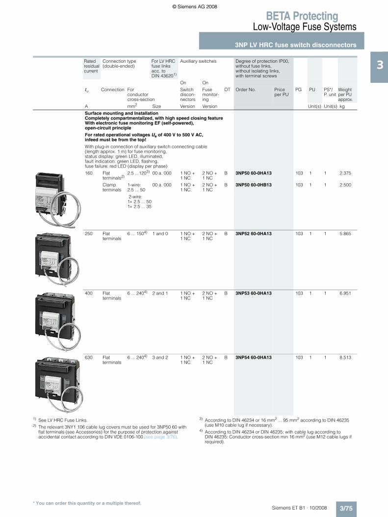
BETA ProtectingLow-Voltage Fuse Systems
3NP LV HRC fuse switch disconnectors
3/75Siemens ET B1 · 10/2008
3
* You can order this quantity or a multiple thereof.
1) See LV HRC Fuse Links.2) The relevant 3NY1 106 cable lug covers must be used for 3NP50 60 with
flat terminals (see Accessories) for the purpose of protection against accidental contact according to DIN VDE 0106-100 (see page 3/76).
3) According to DIN 46234 or 16 mm2 ... 95 mm2 according to DIN 46235 (use M10 cable lug if necessary).
4) According to DIN 46234 or DIN 46235; with cable lug according to DIN 46235: Conductor cross-section min 16 mm2 (use M12 cable lugs if required).
Rated residual current
Connection type (double-ended)
For LV HRC fuse links acc. to DIN 436201)
Auxiliary switches Degree of protection IP00, without fuse links, without isolating links, with terminal screws
On On
Iu Connection For conductor cross-section
Switch discon-nectors
Fuse monitor-ing
DT Order No. Priceper PU
PG PU PS*/P. unit
Weightper PU approx.
A mm2 Size Version Version Unit(s) Unit(s) kg
Surface mounting and InstallationCompletely compartmentalized, with high speed closing feature With electronic fuse monitoring EF (self-powered), open-circuit principle
For rated operational voltages Ue of 400 V to 500 V AC, infeed must be from the top!
With plug-in connection of auxiliary switch connecting cable (length approx. 1 m) for fuse monitoring, status display: green LED, illuminated, fault indication: green LED, flashing, fuse failure: red LED (display per phase)
160 Flat terminals2)
2.5 ...1203) 00 a. 000 1 NO + 1 NC
2 NO + 1 NC
B 3NP50 60-0HA13 103 1 1 2.375
Clampterminals
1-wire: 2.5 ... 50
00 a. 000 1 NO + 1 NC
2 NO + 1 NC
B 3NP50 60-0HB13 103 1 1 2.500
2-wire: 1× 2.5 ... 50 1× 2.5 ... 35
250 Flatterminals
6 ... 1504) 1 and 0 1 NO + 1 NC
2 NO + 1 NC
B 3NP52 60-0HA13 103 1 1 5.865
400 Flat terminals
6 ... 2404) 2 and 1 1 NO + 1 NC
2 NO + 1 NC
B 3NP53 60-0HA13 103 1 1 6.951
630 Flat terminals
6 ... 2404) 3 and 2 1 NO + 1 NC
2 NO + 1 NC
B 3NP54 60-0HA13 103 1 1 8.513
ET_B1_2009_en.book Seite 75 Freitag, 12. Dezember 2008 9:47 09
© Siemens AG 2008© Siemens AG 2008

BETA ProtectingLow-Voltage Fuse Systems
3NP LV HRC fuse switch disconnectors
3/76 Siemens ET B1 · 10/2008
3
* You can order this quantity or a multiple thereof.
1) See LV HRC Fuse Links. 2) According to DIN 46234 or 16 mm2 ... 95 mm2 according to DIN 46235 (use M10 cable lug if necessary).
All fuse switch disconnectors with flat connections must be used with the relevant cable lug covers (3NY7 101 to 3NY7 141) in order to ensure protection against finger touch according to BGVA3, see the following table.
1) The fuse switch disconnector with mounted cable lug covers, together with molded-plastic covers for distributor/device field/incoming feeder unit, is easy to install in the meter cabinet.
Rated residual current
Connection type (double-ended)
For LV HRC fuse links acc. to DIN 436201)
Auxiliary switches Degree of protection IP00, without fuse links, without isolating links, with terminal screws
On On
Iu Connection Conductor cross-section
Switch discon-nectors
Fuse monitor-ing
DT Order No. Priceper PU
PG PU PS*/P. unit
Weightper PU approx.
A mm2 Size Unit(s) Unit(s) kg
For 40 mm busbar systemCompletely compartmentalized, with high speed closing feature With electronic fuse monitoring EF (self-powered), open-circuit principle
For rated operational voltages Ue of 400 V to 500 V AC, infeed must be from the top!
For busbar width: 12 mm and 5 mm or 10 mm thickness
160 Flat terminals
2.5 ...1202)
with bottom connection
00 and 000 1 NO + 1 NC
2 NO + 1 NC
B 3NP50 65-1HF13 103 1 1 2.776
For 60 mm busbar system
Use switch version "Surface mounting and installation" and busbar adapter, see page 3/82.
Version For fuse switch disconnectors
DT Order No. Priceper PU
PG PU PS*/P. unit
Weightper PU approx.
Unit(s) Unit(s) kg
Quick retaining platesBetween two support railsto EN 60715
3NY1 995
Busbar center-to-center clearance 125 mm
3NP40 10, 3NP40 70
B 3NY1 995 103 1 1/200 0.135
Busbar center-to-center clearance 125 mm
3NP42 70 B 3NY7 322 103 1 1 0.249
Cable lug covers
and finger-safe cover to BGV A3 (1 set = 2 units) for 1 single mounting or 2 adapter devices
3NP40 7 with flat terminal1)
} 3NY7 101 103 1 1 0.065
3NP42 7 } 3NY7 121 103 1 1 0.2203NP43 } 3NY7 131 103 1 1 0.2213NP44 } 3NY7 141 103 1 1 0.319
Terminals (1 set = 3 units)Conductor cross-section70 mm2 ... 150 mm2 3NP42 7 A 3NY7 120 103 1 1 0.333120 mm2 ... 240 mm2 3NP43 A 3NY7 130 103 1 1 0.583150 mm2 ... 300 mm2 3NP44 A 3NY7 140 103 1 1 0.725
Triple terminals(1 set = 3 units)
3NY7 102
For retrofitting on box terminalsconductor cross-sectionsolid/stranded:2.5 mm2 ... 16 mm2
3NP40 13NP40 7
A 3NY7 102 103 1 1 0.131
For mounting on flat terminalsfinely stranded with end sleeve: 2.5 mm2 ... 10 mm2
3NP40 7 B 3NY7 105 103 1 1 0.113
ET_B1_2009_en.book Seite 76 Freitag, 12. Dezember 2008 9:47 09
© Siemens AG 2008© Siemens AG 2008

BETA ProtectingLow-Voltage Fuse Systems
3NP LV HRC fuse switch disconnectors
3/77Siemens ET B1 · 10/2008
3
* You can order this quantity or a multiple thereof.
Version For fuse switch disconnectors
DT Order No. Priceper PU
PG PU PS*/P. unit
Weightper PU approx.
Unit(s) Unit(s) kg
Three-phase busbars 3NP40 1
3NY1 237
Modular width 90 mm = 5 MWFor Iu max = 225 A For 2 switch disconnectors
A 3NY1 237 103 1 1 0.265
3NY1 238
Permissible connection 25 mm2 or supply terminalFor 3 switch disconnectors A 3NY1 238 103 1 1 0.434For 4 switch disconnectors A 3NY1 438 103 1 1 0.650
3NY1 263
Link rails A 3NY1 263 103 1 1 0.267
Covers 3NP40 1 A 3NY1 265 103 1 1 0.012For 1 blank space in 3NY1 238
Feeder terminals(1 Set = 3 units) For Iu max = 225 A Conductor cross-sectionsolid/stranded:25 mm2 ... 95 mm2
Finely stranded with end sleeve: 16 mm2 ... 70 mm
3NY1 236
3NP40 1 A 3NY1 236 103 1 1 0.262
3NY7 481
Overreaching protections 3NP42 73NP433NP44
A 3NY7 481 103 1 1 0.021
Sealing pins(1 package = 10 units)
3NP42 73NP433NP44
A 3NY7 482 103 1 10 0.056
Bar thickness compensations
(1 Assembly kit = 5 units) for only 5 mm thick busbars
3NP42 73NP43
A 3NY7 381 103 1 1 0.064
Fuse carriers
Gray with inscription label with voltage inspection holes
3NP40 1 B 3NY7 003 103 1 1 0.1603NP40 7 B 3NY7 001 103 1 1 0.220
3NY3 035
Auxiliary switches 1 CO 3NP40 1 up to 3NP44 } 3NY3 035 103 1 1 0.004For sizes 000 and 00 with self-tapping screws for sizes 1 to 3 to clip on
Electronically optimized B 3NY3 030 103 1 1 0.004
Fuse links Size 000
3NP40 1
With non-insulated grip lugs, operational class gL/gG for cable and line protection, mounting width 21 mm according to IEC 60269-2-1 and DIN 43620
400 V/125 A A 3NY1 822 013 1 3 0.130400 V/160 A B 3NY1 824 013 1 3 0.129
Signal leadsFor connection to output socket of fuse monitoring, size 001-m cable with connector 3NP40 7 B 3NY1 910 103 1 1 0.0973-m cable with connector 3NP40 7 B 3NY1 911 103 1 1 0.261
�
�����
ET_B1_2009_en.book Seite 77 Freitag, 12. Dezember 2008 9:47 09
© Siemens AG 2008© Siemens AG 2008

BETA ProtectingLow-Voltage Fuse Systems
3NP LV HRC fuse switch disconnectors
3/78 Siemens ET B1 · 10/2008
3
* You can order this quantity or a multiple thereof.
1) When using LV HRC fuse links, size 00 (160 A), the permissible load current is 0.9 x In.
2) To some extent, special masking frames are required for installation in ALPHA wall-mounted and floor-mounted distribution boards (STAB, SIKUS), and ALPHA 400-ZS meter cabinets; see page 3/78.
3) In 60 mm busbar systems, the conductor cross-section is limited to 16 mm2 if the outgoing feeder is at the bottom.
4) If 8GE3 818-0 mounting plates are used, 3NY7 220 molded-plastic mask-ing frames can also be used (for installation in any distribution boards).
Version For fuse switch disconnectors
DT Order No. Priceper PU
PG PU PS*/P. unit
Weightper PU approx.
mm × mm Unit(s) Unit(s) kg
Masking framesFor flush mounting in 40 mm and 60 mm busbar systems
Touch protection covers1)
3NP40 753NP40 76
B 3NY7 601 103 1 1 0.125
Masking framesFor installation in any distribution boards2)
Molded-plastic masking frames
3NY1 251
215 × 130 3NP40 1 A 3NY1 251 103 1 1 0.052215 × 130 3NP40 7 with box terminals } 3NY7 200 103 1 1 0.037215 × 130 3NP40 7 with flat terminals } 3NY7 201 103 1 1 0.046
375 × 220 3NP42 7 } 3NY7 220 103 1 1 0.112375 × 245 3NP43 A 3NY7 230 103 1 1 0.117375 × 290 3NP44 A 3NY7 240 103 1 1 0.125
Masking framesFor installation in ALPHA 400-ZS meter cabinets
Molded-plastic masking frames
Suitable for distribution board/device panel or for incoming feeder unit in the meter cabinet (busbar mounted)
197 × 215.5 2 × 3NP40 1 A 3NY1 258 103 1 1 0.063197 × 215.5 1 x 3NP40 1 left A 3NY1 262 103 1 1 0.093197 × 215.5 1 x 3NP40 1 right A 3NY1 264 103 1 1 0.091
208 × 229 1 x 3NP40 7 left A 3NY7 500 103 1 1 0.120208 × 229 1 x 3NP40 7 right A 3NY7 501 103 1 1 0.120208 × 236 2 × 3NP40 7 A 3NY7 502 103 1 1 0.054
309 × 216 3NP42 7 } 3NY7 220 103 1 1 0.112375 × 245 3NP43 A 3NY7 230 103 1 1 0.117375 × 290 3NP44 A 3NY7 240 103 1 1 0.125
Masking frames For installation in ALPHA 160- and ALPHA 400 wall-mounted distribution boards (STAB 160/STAB 400), and ALPHA 630 floor-mounted distribution boards (SIKUS 630)
Touch protection covers1)3)
3NP40 76 B 3NY7 600 103 1 1 0.095
Molded-plastic masking frames
For mounting on mounting plates or busbars. Further information see Catalog ET A1 "ALPHA distribution boards and terminal blocks"
166 × 199 1 × 3NP40 1 right A 3NY1 260 103 1 1 0.082166 × 199 1 × 3NP40 1 left A 3NY1 261 103 1 1 0.086166 × 199 2 × 3NP40 1 A 3NY1 248 103 1 1 0.036
208 × 229 1 × 3NP40 7 left A 3NY7 500 103 1 1 0.120208 × 229 1 × 3NP40 7 right A 3NY7 501 103 1 1 0.120208 × 236 2 × 3NP40 7 A 3NY7 502 103 1 1 0.054
309 × 2164) 3NP42 7 A 3NY7 820 103 1 1 0.113375 × 245 3NP43 A 3NY7 230 103 1 1 0.117375 × 290 3NP44 A 3NY7 240 103 1 1 0.125
Masking framesFor installation in 8HP molded-plastic distribution systems
Molded-plastic masking frames
For installation in 8HP complete enclosures with fuse switch disconnectors 8HP enclosure (size)
1 1 × 3NP40 10 A 8HP6 431 046 1 1 0.2211 1 × 3NP40 70 A 8HP6 422 046 1 1 0.224
2 2 × 3NP40 10 A 8HP6 432 046 1 1 0.4652 3 × 3NP40 10 A 8HP6 432 046 1 1 0.4652 1 × 3NP40 70 A 8HP6 423 046 1 1 0.2302 2 × 3NP40 70 A 8HP6 424 046 1 1 0.203
2.5 1 × 3NP40 70 A 8HP6 423 046 1 1 0.2302.5 2 × 3NP40 70 A 8HP6 424 046 1 1 0.2032.5 1 × 3NP42 70 A 8HP6 427 046 1 1 0.250
�����
���
ET_B1_2009_en.book Seite 78 Freitag, 12. Dezember 2008 9:47 09
© Siemens AG 2008© Siemens AG 2008

BETA ProtectingLow-Voltage Fuse Systems
3NP LV HRC fuse switch disconnectors
3/79Siemens ET B1 · 10/2008
3
* You can order this quantity or a multiple thereof.
Version For fuse switch disconnectors
DT Order No. Priceper PU
PG PU PS*/P. unit
Weightper PU approx.
mm × mm Unit(s) Unit(s) kg
Molded-plastic masking framesFor installation in 8HP molded-plastic distribution systems
For mounting between 2 standard mounting rails with 3NY1 995 quick retaining plate
197 × 215.5 1 × 3NP40 10 right, with and withoutauxiliary switch
A 3NY1 256 103 1 1 0.116
197 × 215.5 1 × 3NP40 10 left, with and without auxiliary switch
A 3NY1 257 103 1 1 0.118
In a field of width B1 197 × 215.5
2 × 3NP40 10, with and without auxiliary switch
A 3NY1 258 103 1 1 0.063
3NY1 250
In a field of width B2/2 197 × 235
2 × 3NP40 10, with and without auxiliary switch
A 3NY1 250 103 1 1 0.075
3NY1 253
In a field of width B2 197 × 485
3 × 3NP40 10 with and without auxiliary switch (supports included in delivery)
B 3NY1 253 103 1 1 0.225
197 × 485 4 × 3NP40 10 with and without auxiliary switch (supports included in delivery)
B 3NY1 254 103 1 1 0.188
3NY1 255
197 × 485 5 × 3NP40 10, with and without auxiliary switch
A 3NY1 255 103 1 1 0.125
Supports
(1 set = 10 units) for 3NY1 253 and 3NY1 254 molded-plastic masking frames
3NP40 1 C 3NY1 271 103 1 1 0.100
Molded-plastic masking frames
3NY1 260
For mounting on 3NP40 1 switch disconnectors, 166 × 199
1 × 3NP40 1 right with and without auxiliary switch
A 3NY1 260 103 1 1 0.082
On standard mounting rails with special 8GD9 equipment rack and for mounting on busbars (except 3NY1 247) 166 × 199
1 × 3NP40 1 left, with and without auxiliary switch
A 3NY1 261 103 1 1 0.086
In a field of width B1 166 × 199
2 × 3NP40 1, with and without auxiliary switch
A 3NY1 248 103 1 1 0.036
3NY1 247
In a field of width B2 166 × 469
5 × 3NP40 1, with and without auxiliary switch
A 3NY1 247 103 1 1 0.072
Blanking covers(1 set = 10 units) for covering blank spaces in the 3NY1 2 molded-plastic mask-ing frames, width 90
3NP40 1 B 3NY1 270 103 1 1 0.040
ET_B1_2009_en.book Seite 79 Freitag, 12. Dezember 2008 9:47 09
© Siemens AG 2008© Siemens AG 2008

BETA ProtectingLow-Voltage Fuse Systems
3NP LV HRC fuse switch disconnectors
3/80 Siemens ET B1 · 10/2008
3
* You can order this quantity or a multiple thereof.
1) For mounting on 8GD9 590 mounting plate, the 3NY7 220 molded-plastic masking frame can also be used.
2) If retrofitted, drill holes required.
Version For fuse switch disconnectors
DT Order No. Priceper PU
PG PU PS*/P. unit
Weightper PU approx.
mm × mm Unit(s) Unit(s) kg
Molded-plastic masking frames
For mounting between two standard mounting rails
208 × 219 1 × 3NP40 7 left B 3NY7 800 103 1 1 0.100208 × 219 1 × 3NP40 7 right B 3NY7 801 103 1 1 0.120With 3NY1 995 quick retaining plate 208 × 222
2 × 3NP40 7 B 3NY7 802 103 1 1
With 3NY1 322 quick retaining plate 309 × 216
1 × 3NP42 7 A 3NY7 820 103 1 1 0.113
Molded-plastic masking frames
For fixing on 8GD9 100 mounting plates
208 × 229 1 × 3NP40 7 left A 3NY7 500 103 1 1 0.120208 × 229 1 × 3NP40 7 right A 3NY7 501 103 1 1 0.120208 × 236 2 × 3NP40 7 A 3NY7 502 103 1 1 0.054309 × 2161) 1 × 3NP42 70 A 3NY7 820 103 1 1 0.113
Molded-plastic masking frames
For fixing on 8GD9 591 mounting plates375 × 245 1 × 3NP43 70 A 3NY7 230 103 1 1 0.117
For fixing on 8GD9 592 mounting plates375 × 290 1 × 3NP44 70 A 3NY7 240 103 1 1 0.125
Fuse carriers
3NY1 074
3NP50 6.-.C..0 B 3NY1 074 103 1 1 0.6203NP52 60-.C..0 B 3NY1 371 103 1 1 0.2633NP53 60-.C..0 B 3NY1 372 103 1 1 1.5103NP54 60-.C..0 B 3NY1 373 103 1 1 1.690
With fuse monitoring by 3RV1 motor starter protectors
3NP50 6.-.E..6 B 3NY1 420 103 1 1 1.4053NP52 60-.E..6 B 3NY1 421 103 1 1 1.900
(with auxiliary switches, 1 NO + 1 NC), with plug-in connection, without connector and connecting cable
3NP53 60-.E..6 B 3NY1 422 103 1 1 1.9803NP54 60-.E..6 B 3NY1 423 103 1 1 2.600
Connector and connecting cable 1 m long 3NP5 with 3RV1 B 3NY1 910 103 1 1 0.0973 m long B 3NY1 911 103 1 1 0.261
3NY1 513-3
With electronic fuse monitoring for 400 V ... 500 V DC
3NP50 6.-.H.13 B 3NY1 513-0 103 1 1 1.2353NP52 60-.H.13 C 3NY1 513-2 103 1 1 2.130
(with auxiliary switches, 2 NO + 1 NC), with plug-in connection, without connector and connecting cable
3NP53 60-.H.13 B 3NY1 513-3 103 1 1 2.1463NP54 60-.H.13 C 3NY1 513-4 103 1 1 0.325
3NY1 915
Connector and connecting cable (6P)
3NP5 with EF B 3NY1 915 103 1 1 0.372
3 m long
Auxiliary switches 1 NO + 1 NC
3NY3 033
With actuating cams, screws and washers (mounting kit)
3NP502) B 3NY3 033 103 1 1 0.015
3NY3 034
With fixing bracket and screws (mounting kit)
3NP52 ... 3NP54 B 3NY3 034 103 1 1 0.015
ET_B1_2009_en.book Seite 80 Freitag, 12. Dezember 2008 9:47 09
© Siemens AG 2008© Siemens AG 2008

BETA ProtectingLow-Voltage Fuse Systems
3NP LV HRC fuse switch disconnectors
3/81Siemens ET B1 · 10/2008
3
* You can order this quantity or a multiple thereof.
Version For fuse switch disconnectors
DT Order No. Priceper PU
PG PU PS*/P. unit
Weightper PU approx.
mm × mm Unit(s) Unit(s) kg
Arc chutes
3NY4 031
3NY4 011
(for 3NP52, 3NP53 and 3NP54, 3 units each are required)
3NP50 B 3NY4 031 103 1 1 0.2183NP52 B 3NY4 011 103 1 1 0.2153NP53, 3NP54 B 3NY4 012 103 1 1 0.240
Molded-plastic masking frames
As replacement for masking frames from assembly kits for flush mounting (without fixing brackets and smallcomponents)
300 × 220 3NY1 210 A 3NY1 102 103 1 1 0.071300 × 245 3NY1 211 A 3NY1 103 103 1 1 0.075300 × 290 3NY1 212 A 3NY1 104 103 1 1 0.084
Molded-plastic masking frames, for installation in any distribution board
For installation in cabinet 215 × 135 3NP50 with and without
auxiliary switchA 3NY1 105 103 1 1/400 0.045
215 × 135 With auxiliary switch A 3NY1 115 103 1 1/400 0.044
For installation in metal front panels220 × 160 With and without
auxiliary switchA 3NY1 125 103 1 1 0.062
For covering connection terminals265 × 135 3NP50 with and without
auxiliary switchA 3NY1 107 103 1 1 0.073
For covering cable lug connections290 × 135 3NP50 with and without
auxiliary switchA 3NY1 106 103 1 1/225 0.071
For separate covering of top and bottom cable lug connections290 × 135 With auxiliary switch A 3NY1 116 103 1 1/225 0.071290 × 135 3NP50 with and without
auxiliary switchA 3NY1 108 103 1 1/200 0.048
3NY1 212
Assembly kits for flush mountingWith molded-plastic masking frames, fixing brackets and small components. For disconnectors with and withoutauxiliary switch
250 × 149 3NP50 60 B 3NY1 208 103 1 1 0.531300 × 220 3NP52 60 B 3NY1 210 103 1 1 0.287300 × 245 3NP53 60 B 3NY1 211 103 1 1 0.298300 × 290 3NP54 60 B 3NY1 212 103 1 1 0.313
ET_B1_2009_en.book Seite 81 Freitag, 12. Dezember 2008 9:47 09
© Siemens AG 2008© Siemens AG 2008

BETA ProtectingLow-Voltage Fuse Systems
3NP LV HRC fuse switch disconnectors
3/82 Siemens ET B1 · 10/2008
3
* You can order this quantity or a multiple thereof.
1) Also available in 2-wire version: 1 × 2.5 mm2 ... 50 mm2 and 1 × 2.5 ... 35 mm2.
2) Switch is wider than adapter; however, this can be expanded to 276 mm using two 8US19 98–2BM00 lateral modules.
Version For fuse switch disconnectors
DT Order No. Priceper PU
PG PU PS*/P. unit
Weightper PU approx.
Unit(s) Unit(s) kg
Covers for cable lug connection(1 set = 6 units) screw-on to free screw end for protection against unintentional contact
3TX6 546-3B
Covering length, 99 3NP52 A 3NY1 241 103 1 1 0.205Covering length, 95 3NP53 3NP54 B 3TX6 546-3B 101 1 1 0.260Covering length, 120 B 3NY1 245 103 1 1 0.336
3NY1 907
Clamp terminals(1 set = 3 units)
2.5 ... 50 mm2 1) 3NP50 B 3NY1 903 103 1 1 0.10835 ... 120 mm2 3NP52 B 3NY1 907 103 1 1 0.225
8US12 10-4AG00
Busbar adapters
For 60 mm busbar systemBusbar width
108 3NP50 A 8US12 91-4SB00 143 1 1 0.551250 (length 320 mm, M10 terminal screws, connecting cables must be made)
3NP52, 3NP53, 3NP542) A 8US12 10-4AG00 143 1 1 3.060
Sealing eyes
Can be retrofitted (1 package = 10 units)
3NP50 B 3NY1 940 103 1 1 0.010
ET_B1_2009_en.book Seite 82 Freitag, 12. Dezember 2008 9:47 09
© Siemens AG 2008© Siemens AG 2008

BETA ProtectingLow-Voltage Fuse Systems
3NP LV HRC fuse switch disconnectors
3/83Siemens ET B1 · 10/2008
3
* You can order this quantity or a multiple thereof.
■ Dimensional drawings
3NP40 10 3NP40 10 3NY1 995 quick retaining plateCutout for 3NP35 and 3NP40 10
With 3NY1 995 quick retaining plate, mount-ing rail center-to-center clearance: 125 mm
For 3NP40 10 and 3NP40 70
3NP40 10 With three-phase 3NY1 237 busbars For 2 fuse switch disconnectors
3NY1 265 caps For three-phase 3NY1 238 busbars
3NP40 10 With 3NY1 235 triple terminals
3NP40 10 With 3NY1 236 feeder terminals
3NP40 10 With 3NY1 251 molded-plastic masking frames
3NP40 15-1CJ01 With busbar adapter, flat, busbar width 12 mm or 15 mm and thickness 5 mm or 10 mm, with bottom connection
3NP40 15-1CK01 With busbar adapter, flat, busbar width 12 mm or 15 mm and thickness 5 mm or 10 mm, with top connection
3NP40 15-0CJ01 With busbar adapter, deep, busbar width 12 mm or 15 mm and thickness 5 mm or 10 mm, with bottom connection
3NP40 16-1CJ01 With busbar adapter, rails of width 12, 15, 20 mm or 30 mm and thickness 5 mm or 10 mm, flat, T, I profiles and other renowned busbar systems, with bottom connection
3NP40 16-1CK01 With busbar adapter, rails of width 12, 15, 20, 25 mm or 30 mm and thickness 5 mm or 10 mm, flat, T, I profiles and other renowned busbar systems, with top connection
73,544
127,
5
64,5 44
,5
25,5 25,5
NSE0_00190b
4844
52 Ø5,8
50 143
126,
5
174
27
168,
5Auxiliary switch
85
125
NS
E0
0019
2a
5097,5
43,5
2,5
M5
Ø5,8
70
NS
E0_
0019
3a
97,5
43,5
85
7013
,8
7,517,5
28,5
34,5
50
M5
For installation in STAB 8GD wall-mounted distribution boards, upper perforations with 50 mm clearance are required.
M 5
50
100
155
68
NS
E0_
0019
1a
NS
E 0
0196
b
9,5
18
1618
NS
E 0
0197
b
62,5
2121 28 3,5
28,5
62,5
2121 283,5
3520
NS
E0_
0019
4b
63 28,5
14 7210,5 5
1335
12
NSE0_00195a
130
NSE0_ 00200b
41,5
215
58,5
30
174
89 100,5
NS
E 0
0201
b
25,5 25,5 201
19
16,5
4040144,
57,
5 18
72
89 100,5
NS
E 0
0202
b
25,5 25,5 72
19
16,5
4040144,
57,
5 18
201
89
NS
E 0
0907
b
25,5 25,5
16,5
4014
4,5
40
7,5
19 121,5
18
93222
89
NS
E 0
0204
b
25,5 25,5
10,5
6060
168
11,5
14
69,519 100,5
20172
89
NS
E 0
0205
b
25,5 25,5 1060
6016
811
,5
7214
69,519 100,5
201
ET_B1_2009_en.book Seite 83 Freitag, 12. Dezember 2008 9:47 09
© Siemens AG 2008© Siemens AG 2008

BETA ProtectingLow-Voltage Fuse Systems
3NP LV HRC fuse switch disconnectors
3/84 Siemens ET B1 · 10/2008
3
* You can order this quantity or a multiple thereof.
1) h = distance from upper edge of switchboard cutout to center of disconnector mounting.
2) Masking frame is placed open on the switchgear cabinet panel, for cover behind control cabinet panel: cutout dimensions on request.
3NP40 70 For mounting
3NP42 70, 3NP43 70, 3NP44 70 For mounting
Drilling pattern for 3NP40 70
3NY73 22 quick retaining plate Drilling pattern for 3NP42 70
3NP40 75-0 With busbar adapter, deep, busbar width 12 mm or 15 mm and thickness 5 mm or 10 mm
Drilling pattern for 3NP43 70 Drilling pattern for 3NP44
3NP40 75-1 With busbar adapter, flat, busbar width 12 mm or 15 mm and thickness 5 mm or 10 mm
$ Bottom edge disconnector-base % Center disconnector-base
For plastic frames Cutouts2) for 3NP40 70 Cutouts2) for 3NP42
For metal frames Cutouts for 3NP4
Cutouts2) for 3NP43 Cutouts2) for 3NP44
NS
E0_
0020
6b
108
83,5
17
170
45 36,516
1
190
50
70
101
83,5
NS
E0_
0020
7b
dc
eb
a
f f
NS
E0_
0020
8a
50
70
83,5
Ø5,8
1
Type a b c d e f
3NP42 70 184 243 66 45.5 215 573NP43 70 210 288 80 48 255 653NP44 70 256 300 94.5 48 267 81
NSE0_00522a
122,5
M 685 81
,797
,5
116
114
85
130
50
NS
E0_
0021
0b
2Ø6,5
Ø11
NS
E0_
0020
9a
19 132
4040
130
1616
1
108
8417
170
93
50
70
238 65
50
65
Ø11NSE0_00211b
2
81
50
81
Ø11NSE0_00212a
2
NS
E0_
0021
3a
72
19 111
4040
130
1616
1
217
108
8417
170
50
70
NS
E0_
0052
3a
118
Ø5,8
5070 11
019
5
NS
E0_
0052
4a
198
Ø11
114116
157
274,
4
130
25 50
NSE
0_00
906b
B
hH
Type Masking frame between assembly kit
Min. panel cutout
Molded-plastic masking frame behind panelType B H B H h1)
3NP40 1 3NY1 251 130 215 100 180 1003NP40 7 3NY7 200,
3NY7 201130 215 118 195 110
3NP42 7 3NY7 220 220 375 210 275 1573NP43 7 3NY7 230 245 375 235 315 1743NP44 7 3NY7 240 290 375 280 325 178
Molded-plastic masking frame in front of panelType B H B H h1)
3NP40 1 3NY1 251 130 215 100 155 873NP40 7 3NY7 200,
3NY7 201130 215 118 195 110
3NP42 7 3NY7 220 220 375 198 275 1573NP43 7 3NY7 230 245 375 224 315 1743NP44 7 3NY7 240 290 375 270 325 178
NSE
0_00
525a
224
174
315
130
50
Ø11
NS
E0_
0052
6a
270
177,
526
7
162
50
Ø11
ET_B1_2009_en.book Seite 84 Freitag, 12. Dezember 2008 9:47 09
© Siemens AG 2008© Siemens AG 2008

BETA ProtectingLow-Voltage Fuse Systems
3NP LV HRC fuse switch disconnectors
3/85Siemens ET B1 · 10/2008
3
* You can order this quantity or a multiple thereof.
1) For VBG4 plus dimension c of cable lug covers (see page 3/76).2) When installed together with size 000 or size 00 in STAB/SIKUS distribution
boards, 3NY7 820 molded-plastic masking frame is used as a depth com-pensation (below).
3NP40 70-0F For mounting and installation
3NP40 75-0F With busbar adapter, deep, 40 mm Busbar width 12 mm or 15 mm and thickness 5 mm or 10 mm
3NP40 75-1F With busbar adapter, flat, 40 mm Busbar width 12 mm or 15 mm and thickness 5 mm or 10 mm
3NP40 76-0F With busbar adapter, flat, 60 mm Busbar width 12 mm or 30 mm and thickness 5 mm or 10 mm
3NP40 76-1 With busbar adapter, busbar width 12 mm to 30 mm and thickness 5 mm or 10 mm, flat, T and I profile
3NP42 75-1 3NP42 76-1 3NP43 76-1 3NP44 76-1
With busbar adapter, busbar width 12 mm to 30 mm and thickness 5 mm or 10 mm, flat, T and I profile
����������
� � � �
� � � �
� � � � �
�����
�
�
� � �
NS
E0_
0090
2b
241,5
21019
160,
716
6440
40
11,6
160,
716
6440
40
220,5
18919
NS
E 0
0903
b 18919
6060
1617
9
220,5N
SE
0_00
904b
64
NS
E0_
0021
4a
10,5
6060
168
72
19 111
169
8417
170
108
186
70
50
217
d
b
aN
SE
0_00
215a
ff
ce
Type a b1) c d e f
3NP42 75-1 184 243 832) 45.5 111 403NP42 76-1 184 243 832) 45.5 111 603NP43 76-1 210 288 97 48 125 603NP44 76-1 256 300 112 48 139 60
ET_B1_2009_en.book Seite 85 Freitag, 12. Dezember 2008 9:47 09
© Siemens AG 2008© Siemens AG 2008

BETA ProtectingLow-Voltage Fuse Systems
3NP LV HRC fuse switch disconnectors
3/86 Siemens ET B1 · 10/2008
3
* You can order this quantity or a multiple thereof.
3NY7 200 molded-plastic masking frameFor 3NP40 7 For installation in any distribution boards
3NY7 201 molded-plastic masking frame For 3NP40 7.- For 3NP40 7.-CA01
3NY7 220 molded-plastic masking frame For 3NP42 For installation in any distribution boards
3NY7 230 molded-plastic masking frame For 3NP43 For installation in any distribution boards
3NY7 240 molded-plastic masking frame For 3NP44 For installation in any distribution boards
3NY7 820 molded-plastic masking frame For 1 3NP42 70 switch disconnector For installation in STAB-/SIKUS distribution boards
3NY7 500 molded-plastic masking frame For 1 3NP40 switch disconnector, left For installation in SIKUS 3200-, STAB 160- and 400- and SIKUS 630 distribution boards
3NY7 501 molded-plastic masking framesFor one 3NP40 switch disconnector, right For installation in SIKUS 3200, STAB 160 and 400 and SIKUS 630 distribution boards
3NY7 502 molded-plastic masking frame For 2 3NP40 switch disconnectors For installation in SIKUS 3200-, STAB 160- and 400- and SIKUS 630 distribution boards
3NY7 600 touch protection coverFor installation in ALPHA distribution boardsFor 3NP40 76 switch disconnectors
3NY7 601 touch protection coverFor 3NP40 75 and 3NP40 76 switch disconnectors
Cable lug cover for 3NP40 7, with 3NY7 101 flat terminal
Cable lug cover for 3NP42 to 3NP44, 3NY7 121, 3NY7 131, 3NY7 141
NS
E0_
0021
6a
130
215
40
NS
E0_
0052
7a
130
215
40
NSE
0_00
217a
375
89
220
NSE
0_00
218a
375
70,5
245
NS
E0_
0021
9a
290
375
67,5
NS
E0_
0022
0a
216
49
309
271
NS
E0_
0022
1a
4620
8
64
229
47
6°
NS
E0_
0022
2a
4620
8
64
229
47
6°
NS
E0_
0022
3c
46
64 108236
208
64
112 3273
385
195N
SE
0_01
605
112
38
2
142
194NS
E0_
0160
4
73123
35
94108
NSE0_00224a
3061
a
bc
NSE0_00225a
Type a b c
3NY7 121 181 65 673NY7 131 207 79 503NY7 141 253 94 47
ET_B1_2009_en.book Seite 86 Freitag, 12. Dezember 2008 9:47 09
© Siemens AG 2008© Siemens AG 2008

BETA ProtectingLow-Voltage Fuse Systems
3NP LV HRC fuse switch disconnectors
3/87Siemens ET B1 · 10/2008
3
* You can order this quantity or a multiple thereof.
1) h = distance from upper edge of switchboard cutout to center of disconnector mounting.
2) With standard molded-plastic masking frame behind panel and corre-sponding switchboard cutout, the standard switching capacity is reduced to the following AC 23B values: at 400 V Ie 160 A, at 500 V from Ie 160 A to 125 A and at 690 V from Ie 100 A to 50 A.
3NP50 60, 160 A For mounting
3NP50 60, 160 A With molded-plastic masking frameFor any type of installation
3NY1 107 molded-plastic masking frames
3NP50 60, 160 A With fuse monitoring by 3RV1 motor starter protectors, with plug-in connector
For plastic frames Cutout For 3NP50 60, with and without auxiliary switches
Cutout For 3NY1 208 mounting kit
For metal frames Cutouts for 3NP5
173
9719
6636384
3416
531
NS
E0_
0022
6a
Ø5,8
M8 2236 36
134 19228
15116 97,5
70
Auxiliary switches
cb
d12
NSE0_00231a
a 45 2
230
36
NSE0_00227b
13530°
30
30°30
Type a b c d
3NY1 105 135 215 95.5 38
3NY1 115 135 215 95.5 38
3NY1 106 135 290 144.5 64
3NY1 108 135 290 144.5 64
3NY1 208 149 250 115 53.5
196
300
NS
E0_
0022
8b
134
228
161,5
9120
5NSE0_00229a
130
5,8
70
NS
E0_
0023
0a
126,5
191
207,
5
6143
NS
E0_
0090
6b
B
hH
Type Masking frame between assembly kit
Min. panel cutout
Molded-plastic masking frame behind panel
Type B H B H h1)
3NP50 6 3NY1 1052) 135 215 130 206 1153NP50 6 3NY1 1253NP52 6 3NY1 210 222 300 210 293 1463NP53 6 3NY1 211 245 300 235 293 1463NP54 6 3NY1 212 290 300 280 293 146
Molded-plastic masking frame in front of panel
Type B H B H h1)
3NP50 6 3NY1 105 135 215 130 205 1153NP50 6 3NY1 208 149 250 143 191 --3NP52 6 3NY1 210 220 300 210 262 132
ET_B1_2009_en.book Seite 87 Freitag, 12. Dezember 2008 9:47 09
© Siemens AG 2008© Siemens AG 2008

BETA ProtectingLow-Voltage Fuse Systems
3NP LV HRC fuse switch disconnectors
3/88 Siemens ET B1 · 10/2008
3
* You can order this quantity or a multiple thereof.
3NP5. 60, 250 to 630 A for mounting 3NP5. 60, 250 to 630 A with molded-plastic masking frame, for mounting
3NP5. 60, 250 to 630 A with fuse monitoring by 3RV motor starter protectors, with plug-in connection
3NP50 65, 160 A with busbar adapter, busbar width 12 mm and thickness 5 mm or 10 mm
3NP50 65, 160 A with busbar adapter, with fuse monitoring by 3RV motor starter protectors, with plug-in connection
3NP5. 60, 160 to 630 A With electronic fuse monitoring EF, with plug-in connection and control cable
3NP50 60, 160 A With electronic fuse monitoring EF, with plug-in connection and control cable
3NP5. 60, 250 to 630 A With electronic fuse monitoring EF, with plug-in connection and control cable
12
60
dd
NS
E0_
0023
2a
o28
251
4 10
fg
r 76ba
i rh
m
920
c
ne e
k l
ØØ
Cutout for 3NP52 60, 3NP53 60 and 3NP54 60
NSE0_00233c
300
u 1076f
w
M8
280
8
NS
E0_
0023
4a
st
262
280
Ø9
1) Through-hole for screw.
Type a b c d e f g h i
3NP52 60 207 202 130 93 62 176 38 41 11.53NP53 60 231 226 130 106 70 192 39 39 11.53NP54 60 276 271 200 111 85 207 40.5 40.5 11.5
k1) l1) m n o q r s t
3NP52 60 M10 M8 336 25 32 212 3.6 156 2103NP53 60 M10 M10 352 25 25 228 4.4 180 2343NP54 60 M10 M10 367 30 25 243 6 225 279
u w x y
3NP52 60 89.5 220 186.5 200.53NP53 60 105.5 245 202.5 216.53NP54 60 120.5 290 217.5 231.5
� �
����������
�
�
63 40
165
NS
E0_
0023
6a
83,5
406319
6
17
31
M8 34
12
2236 36
134
116 18 1945 50
97,5
228
1913,5
302
161,5228
NS
E0_
0023
7a156
18
NSE0_00238a
102136150
NS
E0_
0023
9a
272
228NSE0_00240a
299
xy
ET_B1_2009_en.book Seite 88 Freitag, 12. Dezember 2008 9:47 09
© Siemens AG 2008© Siemens AG 2008

BETA ProtectingLow-Voltage Fuse Systems
3NP LV HRC fuse switch disconnectors
3/89Siemens ET B1 · 10/2008
3
* You can order this quantity or a multiple thereof.
■ Schematics
Function auxiliary contact – main contact at SENTRON 3NP4 and 3NP5
SENTRON 3NP fuse switch disconnectors with fuse monitoring (with 3RV1 motor starter protector, with auxiliary switch 1 NO + 1 NC)
SENTRON 3NP5 fuse switch disconnectors with electronic fuse monitoring
42
0 5 10 15 20 61°
13
14 22
0 5 10 15 20 77°
NS
E_0
0174
e
0 5 10 15 20 70°
21
1
Contact closed
Contact open
For 3NP40 1,and 3NP4. 7
Auxiliary switch
On Off
For 3NP5
13-1421-223NP52 60
3NP54 60
13-1421-223NP50 60
3NP53 60
(1 NO)(1 NC)(3 NO)
(3 NO)
(1 NO)(1 NC)(3 NO)
(3 NO)
On Off
(3 NO)(1 NC)(1 NO)1-4
1-23NP40 1,3NP4. 7
Circuit diagram of main circuit Circuit diagram of auxiliary circuit
Q1 = Fuse switch disconnector Q2 = Motor starter protector K1 = Contactor S1 = ON pushbutton S0 = OFF pushbutton F1 = Overload relay F2 = Control-circuit fuse
� �
� �
�
�
� �
� �
� �
� � � �
�
� �
� �
� �
� � � � � �
� �
� �
��
��
��
��� �
� �
�
�
� � � � � � � � � � �
� � � ! � " �� ������������
�
��
�
�� ��
��� �
��
������
�
��
��
Block diagram
Version "A" (open-circuit principle): Auxiliary switches only pick up if fuse faulty and voltage is applied. Version "R" (closed-circuit principle): Auxiliary contacts pick up as soon as voltage is applied and as long as fuses are intact.
1
11 12 23 24 33 34
6 5 4 3 2
BN BU GY WH RDBK
X1
L1 L2 L3
F1 F2 F3
L1' L2' L3'
NSE0_00177a
Switching stageResistornetwork
Parameterization
Synchroni-zationsignals
Voltages
Micro-controller
LED indication
Operation
Fault F1
Fault F2
Fault F3
Power supply unit
Signal leads
ET_B1_2009_en.book Seite 89 Freitag, 12. Dezember 2008 9:47 09
© Siemens AG 2008© Siemens AG 2008

BETA ProtectingLow-Voltage Fuse Systems
3NP LV HRC fuse switch disconnectors
3/90 Siemens ET B1 · 10/2008
3
* You can order this quantity or a multiple thereof.
■ More information
SENTRON 3NP fuse switch disconnectors
3NP40 10 3NP40 70 3NP52 with opened fuse carrier
The SENTRON 3NP4 and 3NP5 fuse switch disconnectors are climate-proof and meet the requirements of IEC 60947-1, IEC 60947-3 and DIN VDE 0660-107. For use in heavily sulfurous atmospheres, the SENTRON 3NP5 series and the 3NP40 1 and 3NP40 7 versions are available as tinned modules (delivery on request). The SENTRON 3NP5 fuse switch disconnector series also complies with the standard BS 5419 and is approved for use in shipboard systems (use approved fuse links).
All SENTRON 3NP4 and 3NP5 fuse switch disconnectors can be sealed as standard or can be sealed through accessories.
Fuse monitoring by SIRIUS motor starter protector
For fuse monitoring, a SIRIUS motor starter protector is factory-fitted and hard-wired to the fuse carrier of the SENTRON 3NP4 and 3NP5 fuse switch disconnectors. If the fuse carrier is closed, the three conducting paths of the SIRIUS motor starter protector are switched in parallel to the fuse links to be monitored. If the fuse carrier is open, all main current paths of the motor starter protector are off circuit. The internal resistance of the motor starter protector is great enough not to impair the protective function of the monitored fuse links. Failure of a fuse will trip the motor starter protector.
Electronic fuse monitoring EF
For electronic fuse monitoring, the EF monitor is factory-fitted and hard-wired to the fuse carrier of SENTRON 3NP5 fuse switch disconnectors.
The EF monitor works independently of any loads. Failure of a fuse can be relayed to a control room through integrated auxiliary switches (2 NO + 1 NC) by means of a centralized fault indica-tion or used to isolate the load through e.g. a contactor. Actuation of the auxiliary switch depends on the EF version. Version "A" stands for "open-circuit principle", version "R" for "closed-circuit principle" (see block diagram).
If a fuse is tripped, a green LED signal flashes (general fault) and the location of the failed fuse is indicated by a red LED. Using more than one device facilitates identification of the affected branch circuit. The EF monitor is automatically reset to the standby position once the faulty fuses are replaced. This state is indicated visually by the status display (green LED). The EF monitor is also suitable for use in industrial systems badly afflicted by harmonics.
Auxiliary switches
The SENTRON 3NP4 and 3NP5 fuse switch disconnectors can also be retrofitted with auxiliary switches for indicating the switching position of the fuse carrier. One switch block (1 CO) can be mounted on SENTRON 3NP4 fuse switch disconnectors size LV HRC 000 and two switch blocks (1 CO) on sizes LV HRC 00 to LV HRC 3 respectively. SENTRON 3NP5 fuse switch disconnectors can also be delivered with a 2-pole auxiliary switch (1 NO + 1 NC) if required. The version with fuse monitor-ing is fitted with this auxiliary switch as standard.
The auxiliary switch of the motor starter protector can be used for indication purposes or to disconnect the main circuit, e.g. through a contactor. The signal lead for the SENTRON 3NP4 fuse switch disconnector size LV HRC 00 needs to be ordered separately. Sizes LV HRC 1 to LV HRC 3 are connected using flat terminations. Delivery of the SENTRON 3NP5 fuse switch disconnectors includes the signal lead, complete with connector. SIRIUS motor starter pro-tectors cannot be used for fuse monitoring in branch circuits by motor starter protectors where a fault may result in > 220 V DC feedback. In the case of parallel cables and meshed networks, only a voltage difference of > 24 V at the switch will trigger themotor starter protector.
ET_B1_2009_en.book Seite 90 Freitag, 12. Dezember 2008 9:47 09
© Siemens AG 2008© Siemens AG 2008