DATA Data Acquisition Transfer and Analysis Management practices @ JRC.IET 1.

3300 NW 211th Terrace, Hillsboro, OR 97124 Page 1 Ph: +1-503-601-2099 Fax: +1-503-601-6878 Revised April 2, 2012 Copyright © 2012 Obvius, All rights reserved.
Best Practices Guide for Obvius Data Acquisition Products
Part I: Background/general information
Obvius LLC provides industry-leading products for cost effective data gathering, storage and communications. The
company's products fall into three major categories:
1. Data acquisition servers (DAS) – Obvius provides several varieties of data acquisition servers that are designed
gathering and storing interval data from a number of different meters. The DAS also provides options for
communicating the interval data to local or remote database servers using LAN's, phone lines or cellular
communications. This guide will focus on the company's AcquiSuite® (model A8812-1, also A8810 AcquiSuite EMB)
DAS with Modbus communications support.
2. Wireless mesh networking products – the company's ModHopper® line of radio transceivers is the industry's first
designed specifically for wireless Modbus communications and provides wireless RS 485 communications for any
Modbus master/slave network.
3. Input/output modules – Obvius also provides support for a number of Modbus RTU input/output modules to
allow connectivity of both new and existing meters and sensors that do not have Modbus capability.
The AcquiSuite DAS (see Illustration 1, below) provides plug-and-play connectivity for gathering interval data from a
variety of new and existing Modbus meters. The AcquiSuite automatically detects and loads drivers to gather
interval information from a variety of meters, including the following meters (as of 9/16/2011):
Obvius A8332-8F2D Flex IO Module Square-D Power Logic Enercept power meter class 3020
Obvius A8923-11 HD Pulse Module Square-D Power Logic Energy Meter with comm board
Obvius A8923-4 IO Module (4A4P-M2) Square-D Power Logic PM710 Power Logic ION 6200
Obvius R9120 ModHopper Siemens ION 9200
Veris HXO/T-485M Siemens ION 9300, 9330, 9350
Veris Enercept H8035 and H8036 Siemens ION 9510, 9610
Veris H8163 Energy Meter with comm board E-Mon ProMon (modbus version), Class 3000, 3400, 5000
Veris H663 and H704 Branch Current Monitor E-Mon pulse output meters (all)
Veris E30, E31, H8238 Multi Circuit Monitor GE kV2c with Modbus card
Veris E50C, E51C, H8436, H8437 Power Meter Acromag 902MB, 10 channel relay output module
Power Logic ION 6300 Advantech ADAM-4051, 16 channel digital input module
Power Logic ION 7300, 7330, 7350 Advantech ADAM-4068, 8 channel relay output module
Power Logic ION 7500, 7600 PDI BCMS
Power Logic ION 8500
For the most current list, visit the Obvius website:
http://obvius.com/pdfs/TN23-SupportedDeviceList.pdf

3300 NW 211th Terrace, Hillsboro, OR 97124 Page 2 Ph: +1-503-601-2099 Fax: +1-503-601-6878 Revised April 2, 2012 Copyright © 2012 Obvius, All rights reserved.
LAN
Pulse and Analog Inputs
RS 485
Modem
USB Power
Modbus devices are connected to the AcquiSuite by daisy-chaining a two-conductor twisted wire to each of the
meters and then to the RS 485 connection on the DAS. As each device is connected, the AcquiSuite will determine
the device type, load the appropriate drivers and begin logging interval data. All interface with the AcquiSuite is
accomplished using any web browser connected to the network port on the AcquiSuite using a straight-through (or
crossover) cable or hub for local connection or the local area network if available.
For more information on the AcquiSuite, including installation manuals and technical specifications, visit the
Products section of the Obvius website:
http://www.obvius.com
Illustration 1 AcquiSuite A8812-1 connections

3300 NW 211th Terrace, Hillsboro, OR 97124 Page 3 Ph: +1-503-601-2099 Fax: +1-503-601-6878 Revised April 2, 2012 Copyright © 2012 Obvius, All rights reserved.
The ModHopper (model R9120-x) wireless transceiver provides mesh communications in a Modbus format to
support ease of connectivity to any Modbus master/slave network. Used in conjunction with the AcquiSuite, the
ModHoppers provide a complete wireless data acquisition system for installation in existing facilities with minimal
wiring requirements. A typical ModHopper network is shown in Illustration 2 below. Each of the ModHoppers
forms an integral part of the self-configuring and self-healing network that does not require software or a PC for
configuration. Each of the devices can also function as a repeater with no connected Modbus devices in the event
there are “dead” spaces within the building where communications are difficult.
The ModHopper uses an FCC approved unlicensed 900 Mhz radio using frequency hopping spread spectrum (FHSS)
radios to transmit Modbus data between meters and the AcquiSuite. In a standard application, up to 32 Modbus
devices can be connected to each ModHopper and typical transmit distances are up to 1500 ft indoors. The FHSS
radios in the ModHoppers minimize (but do not eliminate) interference from outside radio sources such as cell
phone repeaters or other ISM band radio devices. Best practices in installation (see below) will serve to greatly
improve the success rate for wireless transmission of meter data. For more information about the ModHopper, see
the Products section of the website:
http://www.obvius.com

3300 NW 211th Terrace, Hillsboro, OR 97124 Page 4 Ph: +1-503-601-2099 Fax: +1-503-601-6878 Revised April 2, 2012 Copyright © 2012 Obvius, All rights reserved.
Part II: General best practices guidelines
The following are general guidelines that will help in planning and set up of a ModHopper and AcquiSuite wireless
data acquisition network. Separate sections following will address specific recommendations for site surveys,
installation and commissioning.
This guide assumes that the user has a general working knowledge of the installation and wiring of Modbus RTU
devices, so the primary focus will be on the wireless RS 485 installation. Less emphasis will be placed on the
AcquiSuite and its functionality other than some best practices for locating the AcquiSuite(s) and troubleshooting
installations. For each of the sections in this guide, the best practices will be in the format “BP #x:” with the
practices listed in order of importance whenever practical.
BP #1: The single most important contributor to a successful installation is to always remember that the ModHopper
is a radio and that the installer should be aware of environmental factors that would be likely to impair radio signals.
These factors include other sources of radio signals, large metal objects (e.g., electrical panels) and any obstructed
locations.
BP #2: When installing ModHoppers, always allow at least 10 feet of separation between each radio. Although the
ModHoppers are using FHSS to avoid interference, signals transmitted in frequencies close to the 900 Mhz signals of
the ModHopper will be “seen” by the antennas and will likely result in reduced throughput.
BP #3: The ModHopper functions as a Modbus device on the network, therefore each ModHopper MUST have a
unique Modbus address from all other devices on your Modbus network. Since the ModHopper is a
communications node with multiple connected devices, address conflicts with other devices will seriously impair the
overall network operation. It is advisable to designate a range of Modbus addresses exclusively for the ModHoppers
as this will minimize the likelihood of conflicts and make troubleshooting much easier.
BP #4: Avoid placing ModHoppers in and around heavy steel work or very thick concrete walls. There are unique
ways to work around areas like this. For example in a deep sub basement or below grade parking structure, an easy
solution would be to install one ModHopper at the below grade location. Then run a hardwire from it back to
another ModHopper located above grade and which is 'connected' to other ModHoppers. In this implementation,
you are adding a hop to the overall comms channel, but the overall impact will allow better and more reliable
comms. Another option is to hardwire the basement ModHopper directly to the AcquiSuite, providing a solid line of
communication.
BP #5: Avoid placing ModHoppers in/on/around electrical conduits or near sources of high electrical 'noise' -
generators, powerful antennas, VFD drive electric motors, or other sources which might introduce ambient
interference.
BP #6: Adding more ModHoppers to facilitate long wiring runs should only be done after careful consideration of the
number of “hops” that may be added. In general, the best way to avoid delays in data delivery is to minimize the
number of hops that the data must make to reach the AcquiSuite. In many cases it is more practical (and cost-
effective) to add a hard-wired twisted pair connection if possible to eliminate long linear runs.
3300 NW 211th Terrace, Hillsboro, OR 97124 Page 5 Ph: +1-503-601-2099 Fax: +1-503-601-6878 Revised April 2, 2012 Copyright © 2012 Obvius, All rights reserved.
BP #7: Use shielded twisted-pair 2 conductor wire for hardwired installations, Belden 1120A is a recommended
product for this. Make sure that the color-coding is consistent between + and -.
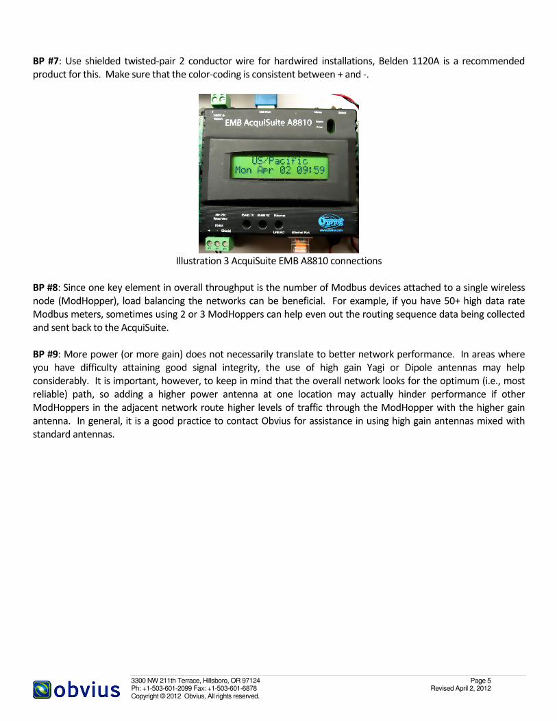
Illustration 3 AcquiSuite EMB A8810 connections
BP #8: Since one key element in overall throughput is the number of Modbus devices attached to a single wireless
node (ModHopper), load balancing the networks can be beneficial. For example, if you have 50+ high data rate
Modbus meters, sometimes using 2 or 3 ModHoppers can help even out the routing sequence data being collected
and sent back to the AcquiSuite.
BP #9: More power (or more gain) does not necessarily translate to better network performance. In areas where
you have difficulty attaining good signal integrity, the use of high gain Yagi or Dipole antennas may help
considerably. It is important, however, to keep in mind that the overall network looks for the optimum (i.e., most
reliable) path, so adding a higher power antenna at one location may actually hinder performance if other
ModHoppers in the adjacent network route higher levels of traffic through the ModHopper with the higher gain
antenna. In general, it is a good practice to contact Obvius for assistance in using high gain antennas mixed with
standard antennas.
3300 NW 211th Terrace, Hillsboro, OR 97124 Page 6 Ph: +1-503-601-2099 Fax: +1-503-601-6878 Revised April 2, 2012 Copyright © 2012 Obvius, All rights reserved.
Part III: Site survey best practices
Note: This section deals primarily with issues related to surveying sites for wireless networks, but it assumes that the
user is familiar with the following:
• Part I: Background/general information of this guide
• Part II: General best practices of this guide
• AcquiSuite installation manual
• ModHopper installation manual
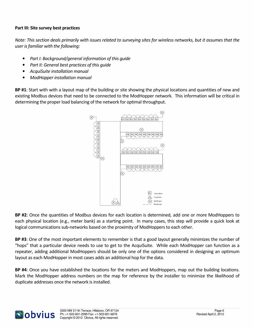
BP #1: Start with with a layout map of the building or site showing the physical locations and quantities of new and
existing Modbus devices that need to be connected to the ModHopper network. This information will be critical in
determining the proper load balancing of the network for optimal throughput.
BP #2: Once the quantities of Modbus devices for each location is determined, add one or more ModHoppers to
each physical location (e.g., meter bank) as a starting point. In many cases, this step will provide a quick look at
logical communications sub-networks based on the proximity of ModHoppers to each other.
BP #3: One of the most important elements to remember is that a good layout generally minimizes the number of
“hops” that a particular device needs to use to get to the AcquiSuite. While each ModHopper can function as a
repeater, adding additional ModHoppers should be only one of the options considered in designing an optimum
layout as each ModHopper in most cases adds an additional hop for the data.
BP #4: Once you have established the locations for the meters and ModHoppers, map out the building locations.
Mark the ModHopper address numbers on the map for reference by the installer to minimize the likelihood of
duplicate addresses once the network is installed.

3300 NW 211th Terrace, Hillsboro, OR 97124 Page 7 Ph: +1-503-601-2099 Fax: +1-503-601-6878 Revised April 2, 2012 Copyright © 2012 Obvius, All rights reserved.
BP #5: Try to arrange the modbus Master unit in the center of the network, to minimize the average number of hops
to any node location. In many applications, it will be advantageous to have ModHoppers that are hardwired to an
AcquiSuite in areas where radio comms may be difficult. Balance the cost of running a twisted pair RS 485 loop with
the number of additional ModHoppers required to get the data back to the AcquiSuite.
BP #6: Arrange units in a star or cluster, and not in a linear configuration. Place the Modbus master device near the
center of the cluster if possible.
BP # 7: Radio traffic is hindered by metal, including metal studs located on interior walls. Locations near outdoor
walls are usually best.
BP #8: Large clusters of modbus devices will require lots of modbus traffic. Keep the number of hops to these
locations at 3 or fewer.
BP #9: Since the ModHopper operates on a 900 MHz FHSS radio, its performance is very similar to a cell phone
operating in the same range. If your cell phone does not work inside the building, it is a good indication that you are
in a challenging environment and you should look carefully at the design in areas where cell coverage is marginal.
This includes transformer vaults, concrete lined basements, below grade parking garages, etc.
3300 NW 211th Terrace, Hillsboro, OR 97124 Page 8 Ph: +1-503-601-2099 Fax: +1-503-601-6878 Revised April 2, 2012 Copyright © 2012 Obvius, All rights reserved.
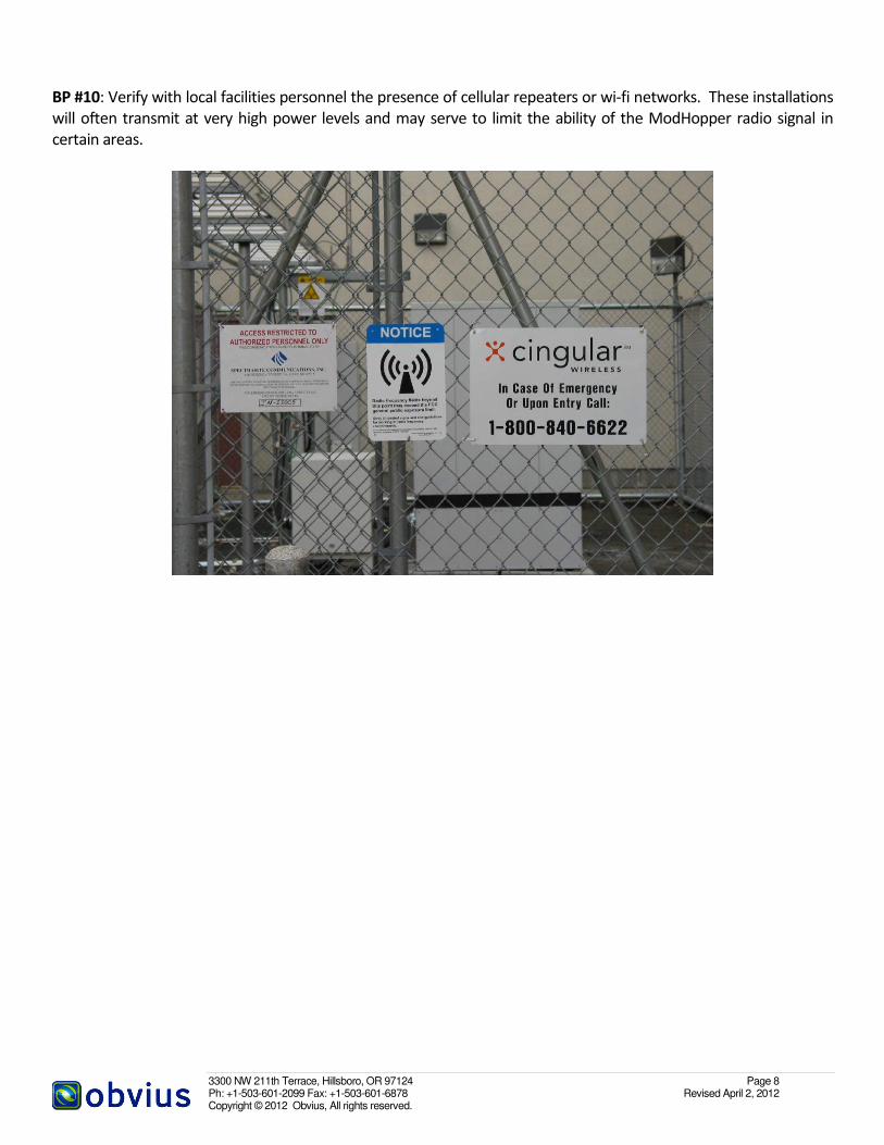
BP #10: Verify with local facilities personnel the presence of cellular repeaters or wi-fi networks. These installations
will often transmit at very high power levels and may serve to limit the ability of the ModHopper radio signal in
certain areas.

3300 NW 211th Terrace, Hillsboro, OR 97124 Page 9 Ph: +1-503-601-2099 Fax: +1-503-601-6878 Revised April 2, 2012 Copyright © 2012 Obvius, All rights reserved.
Part IV: Installation best practices
Note: This section deals primarily with issues related to installation of wireless networks, but it assumes that the user
is familiar with the following:
• Part I: Background/general information of this guide
• Part II: General best practices of this guide
• AcquiSuite installation manual
• ModHopper installation manual
BP #1: Mount the ModHopper a minimum of 10 feet away from any other radio device including other
ModHoppers, cordless phones, and wifi access points. Cellular transmitters and grid arrays require a greater
distance depending on their transmission power.
BP # 2: Do not mount the ModHopper on metal objects. The antenna of the ModHopper must be free and clear of
metal beams, conduit, pipe, ducts, etc.
BP #3: Be aware of what is located on the opposite side of the wall the ModHopper is mounted on. The
ModHopper with the standard antenna broadcasts equally in all directions. If the other side of the wall has, for
example, a large metal enclosure, that metal will severely limit the range of the ModHopper.
3300 NW 211th Terrace, Hillsboro, OR 97124 Page 10 Ph: +1-503-601-2099 Fax: +1-503-601-6878 Revised April 2, 2012 Copyright © 2012 Obvius, All rights reserved.
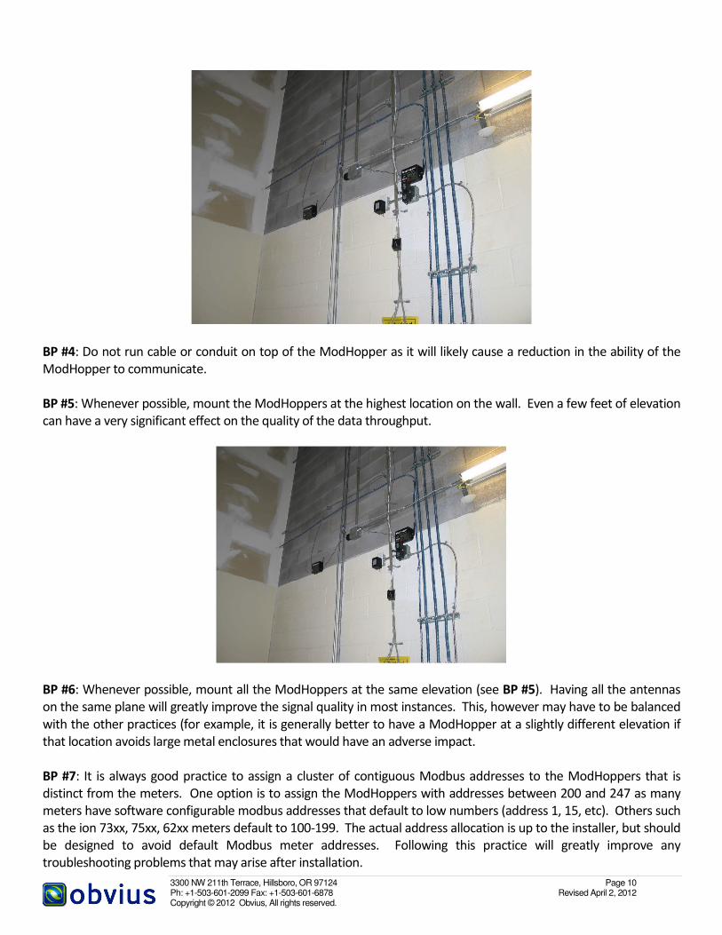
BP #4: Do not run cable or conduit on top of the ModHopper as it will likely cause a reduction in the ability of the
ModHopper to communicate.
BP #5: Whenever possible, mount the ModHoppers at the highest location on the wall. Even a few feet of elevation
can have a very significant effect on the quality of the data throughput.
BP #6: Whenever possible, mount all the ModHoppers at the same elevation (see BP #5). Having all the antennas
on the same plane will greatly improve the signal quality in most instances. This, however may have to be balanced
with the other practices (for example, it is generally better to have a ModHopper at a slightly different elevation if
that location avoids large metal enclosures that would have an adverse impact.
BP #7: It is always good practice to assign a cluster of contiguous Modbus addresses to the ModHoppers that is
distinct from the meters. One option is to assign the ModHoppers with addresses between 200 and 247 as many
meters have software configurable modbus addresses that default to low numbers (address 1, 15, etc). Others such
as the ion 73xx, 75xx, 62xx meters default to 100-199. The actual address allocation is up to the installer, but should
be designed to avoid default Modbus meter addresses. Following this practice will greatly improve any
troubleshooting problems that may arise after installation.

3300 NW 211th Terrace, Hillsboro, OR 97124 Page 11 Ph: +1-503-601-2099 Fax: +1-503-601-6878 Revised April 2, 2012 Copyright © 2012 Obvius, All rights reserved.
Part V: Commissioning best practices
Note: This section deals primarily with issues related to commissioning sites for wireless networks, but it assumes
that the user is familiar with the following:
• Part I: Background/general information of this guide;
• Part II: General best practices of this guide;
• AcquiSuite installation manual;
• ModHopper installation manual;
BP #1: The biggest single mistake in commissioning and troubleshooting is to attempt to bring the entire network
online all at once. This practice makes it extremely difficult to isolate different issues and will virtually insure a
significant amount of wasted time and effort trying to isolate problems. Bringing the overall network up one piece
at a time will provide a solid foundation for wringing out problems as they arise.
BP #2: It is strongly recommended that the AcquiSuite and ModHopper network be established prior to connecting
any devices. This allows the comms network to “settle out” and also provides a much simpler troubleshooting
protocol. Use the AcquiSuite to review the routing information for the ModHoppers. If the AcquiSuite is not
available on VPN, one option is to use a GSM AcquiSuite that does not require network comms to troubleshoot the
initial installation.
BP #3: Once the comms and data acquisition network functionality is established (see BP #2 above), audit your
Modbus addresses. Make absolutely certain that there are no duplicate addresses. It is particularly important that
there is no duplication of addresses between ModHoppers and meters as this will greatly hinder troubleshooting of
the network once everything is brought on line.
BP #4: Bring the meter banks on line one at a time by connecting the RS 485 wire to the comms port on the
ModHopper. Bringing the banks on one at a time will provide an indication of wiring problems, malfunctioning
meters or duplicate addresses that can be isolated to a single location. Allow several minutes for the network to
“settle out” and resolve all the routing for the designated bank before moving on to other locations.
BP #5: As each new bank comes on line, the network will require time to “settle out” and adjust to the additional
devices on the network. After each new meter location is brought on line, use a laptop connected to the AcquiSuite
to verify signal quality of the node and to verify that the appropriate number of devices can be “seen” by the
network as a whole.

3300 NW 211th Terrace, Hillsboro, OR 97124 Page 12 Ph: +1-503-601-2099 Fax: +1-503-601-6878 Revised April 2, 2012 Copyright © 2012 Obvius, All rights reserved.
BP #6: If link quality drops dramatically when a meter bank is brought on line, review the Modbus addresses and
wiring to confirm that the installation and setup of the devices is correct. If this is all correct and there are a large
number of meters on the loop, it may be necessary to add an additional ModHopper to balance the load on the
system.