
BEST PRACTICE IN REHABILITATION OF PELTON TURBINES AS ...
20
- 463 - BEST PRACTICE IN REHABILITATION OF PELTON TURBINES AS APPLIED AT VERMUNTWERK M5 A. Karakolcu, J. Erhard, B. Wittwer Abstract: In the course of rehabilitation of the horizontal two jet turbine Vermuntwerk M5 the runner was replaced and the nozzles as well as the casing internals were modified. Structural analysis including vibration measurements on the mechanical side and numerical flow analysis and model tests on the hydraulic side were performed. The resulting better comprehension of the flow and mechanical features, including loss and fluid-structure mechanisms, made it possible to design optimized new components and define proper modifications of the existing parts. Thanks to a systematic approach to the rehabilitation project and proper use of available analysis tools all requirements of this demanding project were met. Beyond that and in spite of the fact that optimizations in hydraulic and structural design had to be made in order to solve the existing vibration problems of the unit and to ensure smooth operation within the full control range, an important improvement of the performance could be achieved. 1 Introduction / Hydropower Plant Vermuntwerk The hydro power plant of Vermuntwerk, owned by the Vorarlberger Illwerke AG, is located in the central Alps in Partenen in Vorarlberg / Austria. The water is supplied from the lake Vermunt with a gross head of approximately 725 m. The power plant went into operation in 1930 with four one-jet horizontal Pelton turbines, which have been later replaced by four two-jet horizontal machines in 1953 with an output of 30 MW each. The fifth turbine Vermuntwerk M5, whose modernization is discussed and presented in this paper, was installed in 1939. The main data of the turbine Fig. 1. Turbine hall of the HPP Vermuntwerk 17th Intern. Seminar on Hydropower Plants – Pumped Storage in the Context of Renewable Energy Supply Copyright: Institute for Energy Systems and Thermodynamics – Vienna 2012
Transcript of BEST PRACTICE IN REHABILITATION OF PELTON TURBINES AS ...

- 463 -
BEST PRACTICE IN REHABILITATION OF PELTON TURBINES AS APPLIED AT VERMUNTWERK M5
A. Karakolcu, J. Erhard, B. Wittwer
Abstract: In the course of rehabilitation of the horizontal two jet turbine Vermuntwerk M5 the runner was replaced and the nozzles as well as the casing internals were modified. Structural analysis including vibration measurements on the mechanical side and numerical flow analysis and model tests on the hydraulic side were performed. The resulting better comprehension of the flow and mechanical features, including loss and fluid-structure mechanisms, made it possible to design optimized new components and define proper modifications of the existing parts. Thanks to a systematic approach to the rehabilitation project and proper use of available analysis tools all requirements of this demanding project were met. Beyond that and in spite of the fact that optimizations in hydraulic and structural design had to be made in order to solve the existing vibration problems of the unit and to ensure smooth operation within the full control range, an important improvement of the performance could be achieved.
1 Introduction / Hydropower Plant Vermuntwerk The hydro power plant of Vermuntwerk, owned by the Vorarlberger Illwerke AG, is located in the central Alps in Partenen in Vorarlberg / Austria. The water is supplied from the lake Vermunt with a gross head of approximately 725 m. The power plant went into operation in 1930 with four one-jet horizontal Pelton turbines, which have been later replaced by four two-jet horizontal machines in 1953 with an output of 30 MW each. The fifth turbine Vermuntwerk M5, whose modernization is discussed and presented in this paper, was installed in 1939. The main data of the turbine Fig. 1. Turbine hall of the HPP Vermuntwerk
17th Intern. Seminar on Hydropower Plants – Pumped Storage in the Context of Renewable Energy Supply Copyright: Institute for Energy Systems and Thermodynamics – Vienna 2012

- 464 -
Vermuntwerk M5 is shown in the following table:
Turbine M1 – M4 M5 Type horizontal horizontal Number of nozzles 2 2 Rated discharge [m3/s] ≈ 5 6.36 Rated Head [m] 700 700 Power [MW] 30 38 Runner speed [min-1] 500 500 Runner diameter [mm] 2050 2030
Table 1. Main data of the turbines of HPP Vermuntwerk The main targets of the rehabilitation of the turbine M5 was to prevent vibrations which were occurring at loads beyond 30 MW of output, to increase the turbine efficiency, to increase the availability with less maintenance and inspections and to provide the safe usability for the next decades. The power restriction due to the vibrations should be repealed.
2 Systematic approach of rehabilitation projects The potential of constructing new power plants is restricted in many countries of the world, since the economically exploitable water resources are quite exhausted. However, the potential of further optimization and better utilization of existing plants became more and more interesting, which lead to an increasing market for rehabilitation and modernization projects of hydraulic turbines in the last two decades. Rehabilitation projects are mainly launched to increase performance or to improve the safety and maintenance situation. In most cases as also in Vermuntwerk M5, a combination of more than one reason exists and the rehabilitation is not reduced to a sole simple runner replacement. Different new turbine components need to be embedded in old machines, which is a much more challenging task than the construction of a complete new turbine. A systematic approach is therefore essential in any rehabilitation project to properly identify the need, the extend and the most effective way of execution of the rehabilitation of a hydropower plant. Several international guidelines as the IEC 62256 [1] or the EPRI “Hydro Life Extension Modernization Guide” [2] have been introduced providing procedures for utilities, consultants and suppliers in different manner supporting the process of modernization.
2.1 ANDRITZ Hydro Approach Since the nineties ANDRITZ Hydro is proposing to structure rehabilitation projects in three phases [3] as shown in Fig. 2.
17th Intern. Seminar on Hydropower Plants – Pumped Storage in the Context of Renewable Energy Supply Copyright: Institute for Energy Systems and Thermodynamics – Vienna 2012

- 465 -
Feasibility studies are required and are refined iteratively till a first base scenario is established in the Diagnosis phase. The quality of the turbine assessment is here critical and influences directly the performance of the further progress in the complete project. The analysis phase can start once the feasibility of a rehabilitation project is confirmed. Solutions can be iterated and evaluated. Analysis tools such as CFD and model testing as well as experiences from previous projects are of high value to assess these alternatives and select the optimal solution. After completion of both diagnosis and analysis phases the final step Therapy, that means execution of the rehabilitation contract, is started. The rehabilitation project of the turbine Vermuntwerk M5 as shown in the following was performed according to the above described three phase approach, which was one of the key factors for the successful and smooth execution of the rehabilitation.
3 Project development Dependent from different factors as the size of the projects or wishes and capabilities of the owners various options are available to structure a rehabilitation project from a contractual point of view. Contractual schemes can strongly vary, ranging from developed projects with a single supplier to competitive model or even field testing between several suppliers. In the case of Vermuntwerk M5, the initial feasibility studies and preliminary evaluations were performed by the Vorarlberger Illwerke AG before the open tendering process for the rehabilitation of Vermuntwerk was launched. As a potential supplier ANDRITZ Hydro made a first assessment of the turbine characteristic based on a turbine inspection and the information supplied within the specification. Hydraulic and mechanical guarantees were based on this assessment. After establishing the contractual frame deeper analysis were performed to define all details of the chosen alternative.
Fig. 2. Phases of the rehabilitation process
17th Intern. Seminar on Hydropower Plants – Pumped Storage in the Context of Renewable Energy Supply Copyright: Institute for Energy Systems and Thermodynamics – Vienna 2012

- 466 -
3.1 Assessment of existing turbine 3.1.1 Mechanical assessment
3.1.1.1 Vibration measurements The original design of the Vermuntwerk M5 machine set according Fig. 3 has a three radial bearings concept (from left to right the combined radial and axial thrust bearing of the Pelton turbine, the coupling bearing and the exciter end bearing of the generator). The turbine bearing rests on the cast lower casing part of the 2 jet Pelton turbine and directly underneath in its foundation there is an access pit for inspection and maintenance of the bottom part of the turbine. All radial bearings were monitored by two relative shaft vibration sensors each and the turbine bearing additionally was equipped with two absolute bearing vibration sensors in horizontal and axial direction. There is also a keyphasor, a mechanical and an electronic overspeed detection system mounted in between the combined bearing and the shaft coupled bearing oil pump. An additional axial relative shaft vibration sensor was implemented between the axial bearing and the first shaft shoulder. For the refurbishment ANDRITZ Hydro had to optimize the hydraulic design maintaining the existing boundaries. This results in new shaft and Pelton runner design, new nozzle inserts, a new turbine cover and flow guiding casing inserts, which all had to fit into the existing environment without major changes.
Fig. 3. Vermuntwerk M5 Original turbine longitudinal section
17th Intern. Seminar on Hydropower Plants – Pumped Storage in the Context of Renewable Energy Supply Copyright: Institute for Energy Systems and Thermodynamics – Vienna 2012

- 467 -
The Vermuntwerk M5 turbine set had a severe vibration problem at power outputs above 30MW and therefore was limited in automatic operation in the past years although rated for an output of 38MW. Characteristic vibration data from previous measurements on the turbine bearing performed by the operator are shown in Fig. 4 with significant vibration at 150Hz of the axial bearing casing and in Fig. 5 with relative shaft vibration bearing readings in 1X, 2X and 3X together with considerable 50Hz, 125Hz and low 150Hz components.
First fingerprint measurements taken by ANDRITZ Hydro in November 2009 (see Fig. 6 and Fig. 7) showed a first significant increase in turbine bearing absolute vibration in axial direction at 30MW and a huge step up to heavy vibration in axial and horizontal direction above 35MW followed by stochastic rumbling in both turbine bearing directions with v_rms > 20mm/s and noise pressure levels LAeq = 95dB(A) in front of the turbine cover at 37MW two jets operation. Single jet operations of the lower and the upper nozzle in manual serial testing showed still increased but stable turbine bearing absolute vibration in axial and horizontal directions.
Fig. 4. Original turbine bearing axial casing absolute vibration spectra
Fig. 5. Original turbine horizontal relative shaft vibration spectra
150Hz
Fig. 6. Original turbine bearing absolute vibration v_rms [mm/s] - two jets operation
17th Intern. Seminar on Hydropower Plants – Pumped Storage in the Context of Renewable Energy Supply Copyright: Institute for Energy Systems and Thermodynamics – Vienna 2012

- 468 -
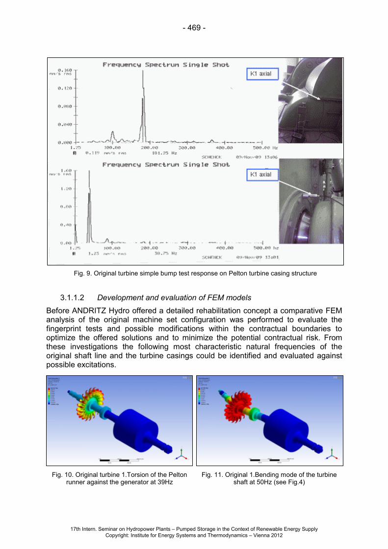
Simple bump tests on a Pelton bucket of the old runner shown in Fig. 8 showed characteristic vibration modes in 125Hz, 150Hz, 181Hz and 236Hz and above. Another bump tests on the Pelton turbine casing structure according Fig. 9 showed characteristic vibration modes at 181Hz at the casing flange, the lower casing shell and the adjacent combined bearing support. A significant response point on 39Hz at the upper shaft cover connection of the turbine cover could also be verified, which later on served for FEM calculation models check for comparison of real vibration behavior.
Fig. 7. Original turbine bearing absolute vibration v_rms [mm/s] - single jet operation
Fig. 8. Original turbine simple bump test response on Pelton bucket
17th Intern. Seminar on Hydropower Plants – Pumped Storage in the Context of Renewable Energy Supply Copyright: Institute for Energy Systems and Thermodynamics – Vienna 2012
- 469 -
Fig. 10. Original turbine 1.Torsion of the Pelton runner against the generator at 39Hz
Fig. 11. Original 1.Bending mode of the turbine shaft at 50Hz (see Fig.4)
3.1.1.2 Development and evaluation of FEM models
Before ANDRITZ Hydro offered a detailed rehabilitation concept a comparative FEM analysis of the original machine set configuration was performed to evaluate the fingerprint tests and possible modifications within the contractual boundaries to optimize the offered solutions and to minimize the potential contractual risk. From these investigations the following most characteristic natural frequencies of the original shaft line and the turbine casings could be identified and evaluated against possible excitations.
Fig. 9. Original turbine simple bump test response on Pelton turbine casing structure
17th Intern. Seminar on Hydropower Plants – Pumped Storage in the Context of Renewable Energy Supply Copyright: Institute for Energy Systems and Thermodynamics – Vienna 2012

- 470 -
Fig. 12. Original 2.Bending mode of the turbine shaft at 126Hz (see Fig.4 and 7)
Fig. 13. Original turbine axial mode of the turbine disc and shaft against generator at 159Hz
The comparison of the vibration data and the simple bump test measurement results showed overall good correlation. The simulation of the axial Eigen mode of the turbine disc and shaft against the heavy generator rotor at 159Hz connected not easily to the forced axial vibration on 150Hz at higher power output. This mode furthermore could not be shifted significantly, as mass proportions and shaft diameters were nearly the same for all new optimized solutions and this mode was less sensitive to bearing stiffness.
However as the FEM simulation model showed proper correlation to all the other measurement results, it was decided to develop and evaluate the new solution from this base after a deeper analysis with a refined model according more detailed measurement results on the 183Hz mode (see Fig. 15).
Fig. 14. Original turbine bending mode of the shaft cover at 40Hz (see Fig.8)
Fig. 15. Original turbine bending mode of the lower casing shell and bearing
17th Intern. Seminar on Hydropower Plants – Pumped Storage in the Context of Renewable Energy Supply Copyright: Institute for Energy Systems and Thermodynamics – Vienna 2012

- 471 -
3.1.2 Hydraulic assessment In every modernization of an existing turbine a hydraulic assessment needs to be done. The main purpose is to identify the best rehab solution from performance point of view and to predict the expected turbine efficiency after installation of new components into an existing environment, which itself is a challenging task [6]. The influence on efficiency of each turbine component of Vermuntwerk M5 starting from the spherical valve over the distributor, nozzles, runner and casing till the tail water channel was analysed. The different hydraulic losses within a component as well as interactions between components and cascade effects were assessed. The excessive vibrations at the existing turbine of Vermuntwerk M5 made it further necessary to analyse already in a very preliminary phase, if any hydraulic excitations could be the source of those vibrations. The effects of following aspects were thereby analysed: • Number of buckets versus angle between the nozzles • Number of buckets with respect to measured vibration frequencies • Number of buckets with respect to jet overlapping • Asymmetric jets due to bends in the inlet piping resulting in axial forces on the
runner The rehabilitation scenario derived from the initial assessment and the analysis included beside a runner replacement casing inserts and optimization of the hydraulic profile of the nozzle in order to further improve the efficiency. In addition flow straighteners in the nozzles were foreseen to eliminate secondary flow structures coming from the upstream bends. Together with optimized number of buckets and improved jet quality any vibrational excitation from a hydraulic source should be eliminated and the turbine efficiency maximized. All analyses and evaluation done in this phase were to be done in a very short time frame, which would not allow any model tests or even CFD simulations. Therefore tools and methods were used which allow a fast and precise assessment, which are especially developed for this purpose and continuously improved by ANDRITZ Hydro.
Fig. 16. Main drawings of Vermuntwerk M5
17th Intern. Seminar on Hydropower Plants – Pumped Storage in the Context of Renewable Energy Supply Copyright: Institute for Energy Systems and Thermodynamics – Vienna 2012

- 472 -
3.2 Development of modernized turbine Vermuntwerk M5 The development of the chosen rehabilitation option of Vermuntwerk M5 can be roughly divided into the hydraulic and mechanical development. It is to be mentioned, that even, if the hydraulic development comes first in the global timeline of the project, all mechanical requirements have to be respected as well. That requires a firm analysis of all fluid structure interactions and hence iterations or parallel work between the hydraulic and mechanical engineering.
3.2.1 Hydraulic development A deeper analysis of all components and options for improvements are done in the hydraulic engineering of the project. Considering the project plan and model time table the hydraulic development concentrated on following components: • Optimization of nozzle geometry and defining optimal hydraulic profile of nozzle
inserts • Modifications on the existing casing and definition of the profiles of additional
casing inserts • Optimal runner design that fits into the existing machine
3.2.1.1 Nozzles
In this phase where the focus is on profile optimization by minimizing hydraulic losses numerical simulation tools gain more importance. The classical mesh based Computational Fluid Dynamics (CFD) methods are well suited for distributor, nozzle and jet analysis. The simulations of Vermuntwerk M5 (Fig. 17) have once again shown that not only the distributor itself but also the upstream piping configuration is of importance. Indeed the bend in the penstock before the inlet valve has influence on the flow pattern in the distributor hence effects also the jet. Several scenarios with nozzle optimizations have been simulated.
Fig. 17. Distributor simulation including upstream piping and jets
17th Intern. Seminar on Hydropower Plants – Pumped Storage in the Context of Renewable Energy Supply Copyright: Institute for Energy Systems and Thermodynamics – Vienna 2012

- 473 -
The finally chosen solution with grids in the nozzle (19) optimally positioned and rotated gives the best jet quality considering secondary flows, jet shape and jet deviation (Fig. 18).
The increased head losses due to the grids in the nozzles are offset by several benefits of the improved jet quality:
• An improved jet without any serious streaks leads to a more precise flow in the bucket and hence reduced losses.
• A jet with decreased dispersion and deviation gives the opportunity to optimize the runner design for a smaller jet diameter. Adaptations on the runner design, which reduce efficiency, in order to allow a smooth operation with a bad jet quality are not anymore needed or can at least be reduced.
• Any axial excitations due to asymmetric jets, which could be a source of the extensive vibrations on the existing unit, are eliminated.
Besides of the numerical analysis comparative tests of the optimized nozzles with grid versus the original design were performed on the model, which also confirmed the results of the theoretical evaluation.
3.2.1.2 Casing
ANDRITZ Hydro has various but complementary methods and tool for assessing and optimizing casings, which are used in different phases of the project. A quick tool based on cinematic methods to predict the water patterns is used for an initial assessment and for the predefinition of casing inserts in the diagnosis phase of the
Fig. 19. Nozzles with grid
Fig. 18. Jet deviations
17th Intern. Seminar on Hydropower Plants – Pumped Storage in the Context of Renewable Energy Supply Copyright: Institute for Energy Systems and Thermodynamics – Vienna 2012

- 474 -
project as well as in the later detail development. The limits of this cinematic method is reached when water sheets exiting from the runner bounce back from the casing or water sheets coming from two jets intersecting each other.
A more sophisticated numerical simulation tool based on the Smoothed Particle Hydrodynamics (SPH) which has been developed and improved since 2004 [8] allows a deeper analysis of the casing. The mesh-less simulation method is perfectly suited to the accurate tracking of water sheets in Pelton casings and to the study of their interaction with casing walls, inserts and the runner. In the frame of the rehabilitation project of Vermuntwerk M5 the output of both tools, with the classic cinematic method and with the novel SPH method (Fig. 20), combined with the experience from previous model and prototypes allowed a precise definition of the casing modifications and inserts. Further optimization loops for the casing were not required during the model tests.
3.2.1.3 Runner
The added value of model tests revealed in the case of Vermuntwerk M5 mainly with the runner development. Thanks to above described engineering methods optimal designs of nozzles and casing modifications were possible. Together with a runner design for the turbine Vermuntwerk M5 based on ANDRITZ Hydro’s patented concave bucket profile the efficiency guarantees were already proven with the initial model setting. However the model tests were not stopped but on the contrary the opportunity to go deeper in analysis of the flow based on measured efficiency results as well as visual flow observations was taken. Hence further optimizations of the flow straighteners and the casing inserts were done. Thanks to a sufficient time frame for the model tests of Vermuntwerk M5 extended runner developments with several alternatives could be performed. Neither classical mesh-based CFD methods nor novel mesh-less SPH methods are currently accurate enough to evaluate efficiencies of different bucket profiles. Nevertheless the support of both CFD methods is useful for bucket profile developments, especially for the understanding and assessment of the flow behaviour in specific local areas of the bucket. The results of such flow simulations together with stress assessments based
Fig. 20. SPH simulation of Vermuntwerk M5 with two jets in operation
17th Intern. Seminar on Hydropower Plants – Pumped Storage in the Context of Renewable Energy Supply Copyright: Institute for Energy Systems and Thermodynamics – Vienna 2012

- 475 -
one Finite Elemente methods give good hints for proper profile modifications in order to increase the efficiency on one side but also to harmonize stresses in the bucket on the other side. With the achieved improvements in the bucket design of Vermuntwerk M5 an important increase of the efficiency compared to the initial model setting could be reached and the guaranteed efficiencies could be clearly surpassed in the model tests as shown in Fig. 27.
3.2.2 Mechanical development Axial excitation from a first view in a Pelton turbine theoretically should not exist. However, at increased flow rates the water jets from the nozzles can deviate enough from the ideal design form and position because of the previous 3D bends of the piping to generate big enough axial force components in the Pelton buckets. So at high flow rates the shaft system of the original machine set was excited also axially on the original 150Hz bucket passing frequency (8,33Hz shaft running frequency times 18 buckets original design, see Fig. 4, Fig. 5 and Fig. 6). Why this effect at single jet operations (see Fig.7) reached not its full amplification could not be proofed in detail. As there were still questions, if the heavy stochastic vibration above 35MW was also partly due to flow problems in the original casing configuration, all possibilities for flow optimization were implemented in the new turbine casing and additional flow improvement devices were installed.
With the new Vermuntwerk M5 runner development the number of buckets was increased from 18 to 22. In that way, the axial excitation through the bucket passing
Fig. 21. Final design of the shaft system vibration Eigen values
17th Intern. Seminar on Hydropower Plants – Pumped Storage in the Context of Renewable Energy Supply Copyright: Institute for Energy Systems and Thermodynamics – Vienna 2012

- 476 -
frequency was increased from 150 to 183,3Hz. Final design of the shaft system vibration Eigen values are presented with considerable margins against the excitation frequencies in Fig.21. This obviously solved the forced axial vibration problem, but as the 183,3Hz excitation was also nearby the original 181Hz casing mode of the lower casing shell and bearing support (see Fig. 8, Fig. 9 and Fig. 13) there was still a risk to face forced turbine casing vibrations at 183,3Hz after the rehabilitation. This Eigen value respectively bending mode was not changed much by enhancing the thickness of the upper turbine casing. Therefore, some provisions for handling eventually increased local turbine casing vibrations and noise emissions were checked as well. A stiffening of the old lower casing out of grey cast iron in order to shift the frequency with some welded outer ribs was not possible but locally bolted heavy steel plates would have helped in this case.
4 Site tests 4.1 Commissioning tests 4.1.1 Final design vibration values From the first start and at all possible operation conditions in steady and also transient conditions the newly refurbished Vermuntwerk M5 Pelton turbine showed excellent absolute bearing and relative shaft vibration conditions, which were recorded on the customers own vibration monitoring system and also cross checked by ANDRITZ Hydro with absolute bearing vibration measurements on the combined turbine bearing in radial and axial direction. In the following figures 22 to 25 the most interesting values of the absolute bearing vibration behaviour are presented, which show maximum radial absolute bearing vibration of v_rms=0,9mm/s at 42MW overload. This is well below the ISO 108016-5:2000 Zone A limit of v_rms=1,6mm/s for nominal design conditions.
Fig. 22. Final design turbine bearing absolute vibration - two jets operation
17th Intern. Seminar on Hydropower Plants – Pumped Storage in the Context of Renewable Energy Supply Copyright: Institute for Energy Systems and Thermodynamics – Vienna 2012

- 477 -
Fig. 24. Final design turbine bearing absolute vibration - overload 42MW
Fig. 25. Final design turbine bearing absolute vibration - 38MW emergency shutdown test
Fig. 23. Final design turbine bearing absolute vibration - single jet operation
17th Intern. Seminar on Hydropower Plants – Pumped Storage in the Context of Renewable Energy Supply Copyright: Institute for Energy Systems and Thermodynamics – Vienna 2012

- 478 -
4.1.2 Final design noise pressure level The excellent vibration characteristic of the “NEW” status also connects to a considerable decrease in the noise pressure level. Due to the optimized hydraulic design, the improved water guidance measures and the new 30 mm thick turbine upper casing ANDRITZ Hydro was able to reach the contractual goals. For an improved aeration of the turbine two openings at the upper casing were provided, which were covered with simple noise dampers. Before final measurements, these two devices had to be modified to reduce their local tonal noise emission on running bucket frequency. Compared with the old turbine the average noise pressure level of the newly refurbished Vermuntwerk M5 turbine was reduced significantly. As shown in Fig. 26, the increase of the noise level from part load to full load was also reduced significantly. As the generator has an average noise pressure level of 84 db(A) at 38 MW the average noise pressure level of the whole Vermuntwerk M5 turbine group is now 85 db(A) at 38 MW.
4.2 Efficiency tests Beside of model tests in accordance to IEC 60193 thermodynamic efficiency tests according to IEC 60041 were performed on the prototype turbine of Vermuntwerk M5 for the final acceptance and verification of the guarantees. As guaranteed an important efficiency increase compared to the original unit could be achieved over the full operation range. The guaranteed efficiency itself was also clearly exceeded as already expected from the model developments. Particularly noticeable is the higher efficiency on the prototype compared to the model results. Of course there are measurement uncertainties but differences of that magnitude cannot be assigned only to uncertainties. One plausible explanation based on flow physics is the difference of head losses between model and prototype in the flow straightener which leads to a higher Reynolds step-up. Another explanation may be found in the different relative importance of jet quality between the model and the high head prototype.
Fig. 26. Comparison of original and final design noise pressure levels
17th Intern. Seminar on Hydropower Plants – Pumped Storage in the Context of Renewable Energy Supply Copyright: Institute for Energy Systems and Thermodynamics – Vienna 2012

- 479 -
Besides all technical aspects the achieved higher efficiency leads also to an important increase of revenue. An increased annual energy production of approximately 712’000 kWh can be derived from the 1.37% efficiency increase compared to the guarantees. In comparison to the efficiency before rehabilitaion the increased annual energy is about 3’100 MWh.
5 Conclusion After rehabilitation of the turbine Vermuntwerk M5 all vibration problems of the existing turbine were solved and an important efficiency increase could be achieved. This horizontal Pelton turbine now offers excellent vibration conditions and hydraulic performance up to 42MW in double jet operation and also single jet operation up to 21MW each. The excellent overall vibration characteristic also supports a considerable decrease in noise pressure level, which was mainly achieved through the optimized hydraulic design, the improved water guidance measures and the new 30mm thick turbine upper casing. Such improvements do not come alone by technological progress that has been made in the meantime after installation of the original unit in 1939. A systematic approach of the rehabilitation project in combination with the proper use of all available analysis tools as numerical simulations in FEM and CFD and appropriate model testing is important but still not fully sufficient. An optimal application of the reasonable measures to a specific turbine requires a comprehensive understanding of all aspects in Pelton technology. To gain and maintain such know-how the large experience accumulated along years from previous prototype and model turbines needs to be consolidated in a practical way as well. Only all these facets together allowed a successful rehabilitation of the turbine Vermuntwerk M5, which was thanks to the good collaboration between Vorarlberger Illwerke AG and ANDRITZ Hydro
Fig. 27. Efficiency measurements of Vermuntwerk M5
17th Intern. Seminar on Hydropower Plants – Pumped Storage in the Context of Renewable Energy Supply Copyright: Institute for Energy Systems and Thermodynamics – Vienna 2012

- 480 -
effectively executed and where all targets of the modernization were met or exceeded. References
[1] IEC 62256, Hydraulic turbines, storage pumps and pump-turbines - Rehabilitation and performance improvement, IEC, 2008
[2] Hydro Life Extension and Modernization Guides: Volume 1 to 7, EPRI, Palo Alto, CA: 1999
[3] Parkinson E., Heimann A., Hauser H.P., Vullioud G., Keck H., Keiser W., Richerd P., Rothenfluh M.: “Systematic Approach of Pelton Rehabilitation Projects: Practical Experience from Case Studies”, HydroVision 2008
[4] Karakolcu A., Geppert L., Marongiu J.-C.: “Performance prediction in Pelton rehabilitation projects”, Seminar on Hydropower Plants, Vienna 2010
[5] Schedelberger J., Karl L.: “Bericht über die thermodynamische Wirkungsgradmessung an der Peltonturbine M5 des KW Vermunt der VIW im März 2012”, Vienna 2012
[6] Karakolcu A., Geppert L., Marongiu J.-C.: “Performance prediction in Pelton rehabilitation projects”, Seminar on Hydropower Plants, Vienna 2010
[7] Parkinson E., Marongiu J.-C., Garcin H., Bissel C.: “From classical to novel flow simulation methods applied to Pelton rehabilitation projects”, Hydro 2010, Lisbon
[8] Marongiu J.-C., Leboeuf F., Caro J., Parkinson E.: “Numerical simulation of the flow in a Pelton turbine using the meshless mehod SPH”, Hydro 2006, Porto Carras, Greece, 2006
Author(s)
Adem KARAKOLCU ANDRITZ HYDRO AG Hardstrasse 319/Postfach 2602 8021 Zuerich, Switzerland Phone: +41 (44) 275 8021 Fax: +41 (44) 275 8081 E-Mail: [email protected] Adem Karakolcu graduated in Mechanical Engineering from Vienna University of Technology. He joined Andritz Hydro in 2006 as development and project engineer for Pelton turbines focusing on cavitation prediction, loss analysis, hydraulic layout and hydraulic engineering. Since 2010 he is responsible for hydraulic engineering within the R&D department for Pelton turbines.
17th Intern. Seminar on Hydropower Plants – Pumped Storage in the Context of Renewable Energy Supply Copyright: Institute for Energy Systems and Thermodynamics – Vienna 2012

- 481 -
Dr. Johannes ERHARD ANDRITZ HYDRO AG Statteggerstraße 18 8045 Graz, Austria Phone: +43 (316) 6902 1348 Fax: +43 (316) 6902 406 E-Mail: [email protected] Johannes Erhard graduated in Mechanical Engineering from Graz University of Technology in 1994. He earned his PhD on the Institute for Thermal Turbomachinery and Machine Dynamics in 2000 on the “Design, Construction and Commissioning of a Transonic Test-Turbine Facility”. Afterwards he worked for ELIN generators in Weiz on R&D, several mechanical measurement and design topics for seven years, before he joined Andritz Hydro in 2007 in the large pumps division, first focusing on FEM calculations and since 2009 in mechanical design as project engineer. There he supported the Andritz Hydro Service as project engineer for Vermuntwerk M5 in design and calculation, vibration optimization and commissioning. Bernhard WITTWER Vorarlberger Illwerke AG Batloggstraße 36 6780 Schruns, Austria Telefon: +43 5556 701-86261 Fax: +43 5556 701-86223 E-mail: [email protected] Bernhard Wittwer graduated in Mechanical Engineering from Graz University of Technology in 2009. He is employed by Vorarlberger Illwerke AG since 2010. In his function as project engineer for Vermuntwerk M5 he supervised the rehabilitation of the existing machine parts and he was responsible for the supplier support.
17th Intern. Seminar on Hydropower Plants – Pumped Storage in the Context of Renewable Energy Supply Copyright: Institute for Energy Systems and Thermodynamics – Vienna 2012

- 482 -
17th Intern. Seminar on Hydropower Plants – Pumped Storage in the Context of Renewable Energy Supply Copyright: Institute for Energy Systems and Thermodynamics – Vienna 2012


![Pelton Turbines [Compatibility Mode]](https://static.fdocuments.us/doc/165x107/55cf92f8550346f57b9ab6bd/pelton-turbines-compatibility-mode.jpg)