
Best Practice Human Factors Guidance for Control...
75
Highways Consultancy Group - Highways Research Group Best Practice Human Factors Guidance for Control Room/HMI Design Contract Reference: 2/1308 Task Reference: 166(1308)MOTT Project Sponsor: Stuart White Date: November 2010
Transcript of Best Practice Human Factors Guidance for Control...

Highways Consultancy Group - Highways Research Group
Best Practice Human Factors Guidance for
Control Room/HMI Design
Contract Reference: 2/1308
Task Reference: 166(1308)MOTT
Project Sponsor: Stuart White
Date: November 2010

Task Reference 166(1308)MOTT Page i
Report Title: HF Guidance
Executive Summary
Control room, plant and equipment design can have a huge impact on human performance.
Designing tasks, equipment and work stations to suit the user can reduce human error, accidents and
ill-health. Failure to observe human factors principles can have serious consequences for individuals
and for the whole organisation. Effective consideration of human factors will make work safer,
healthier and more productive.
The fundamental and consistent philosophy of human factors is to ensure that the human element, or
user, is of principle concern within the design process. This approach promotes the inclusion of user
(and operator) needs, capabilities, limitations and goals into the design process.
This document contains guidance to summarise the best practice human factors approach to
system/product design and development, within the general project lifecycle, in order to provide
support to Highways Agency in creating more cost effective and usable designs. This guidance
should prove useful to both Highways Agency project sponsors/managers and human factors
specialists involved in Highways Agency system/product design and development projects.
This document also contains a simple flowchart and checklist to allow the reader to determine
whether the guidance is relevant to their project, and if so, which parts of the guidance should be
focused on.
The guidance presented in this document provides some simple steps that you can include within the
project plan and supports the reader in this through raising a number of questions for consideration.
The guidance can be read as a whole, or the reader can focus on the sections of particular relevance
to their situation.
A number of case studies and tips have been presented within this document. These have been
collected during the course of this work and are used to provide examples and context for the best
practice/methods that are described.

Task Reference 166(1308)MOTT Page ii
Report Title: HF Guidance
List of Contents
Section 1 - Introduction .............................................................................................. 7
1.1 Human Factors......................................................................................................................7
1.2 Benefits of Human Factors ...................................................................................................8
1.3 Purpose of this document .....................................................................................................9
1.4 Using this document ...........................................................................................................10
Section 2 - Is This Guidance Relevant To Your Project? ......................................... 11
Section 3 - Human Factors Guidance ...................................................................... 16
Step 1 - Clarify goals and requirements ................................................................... 17
Step 2 - Define operator tasks.................................................................................. 20
Step 3 - Allocate tasks to the people or the technology/system ............................... 22
Step 4 - Define the task requirements ...................................................................... 24
Step 5 - Design the job and work organisation ......................................................... 28
Step 6 - Test the early design ideas ......................................................................... 31
Step 7 - Develop conceptual design......................................................................... 35
Step 8 - Test the conceptual design ......................................................................... 36
Step 9 - Develop detailed design ............................................................................. 37
Step 10 - Test the detailed design............................................................................ 42
Step 11 – Gather operational feedback.................................................................... 44
References............................................................................................................... 45
Appendix A – Best Practice Design and Development Process ............................ 46
A1 The human factors approach to design ...........................................................................................46
A2 The ‘rules’ of human factors ............................................................................................................47
A3 The design of control centres ..........................................................................................................50
Appendix B – How do I seek specialist Human Factors advice? ........................... 52
Appendix C – Justification for not seeking advice from a Human Factors Specialist .
........................................................................................................... 53
Appendix D – Justification for seeking advice from a Human Factors Specialist... 54

Task Reference 166(1308)MOTT Page 3
Report Title: HF Guidance
Appendix E – No requirement to seek advice from a Human Factors
Specialist/review Human Factors Guidance............................................................. 55
Appendix F – Justification for reviewing Human Factors Guidance....................... 56
Appendix G – Justification for not reviewing the Human Factors Guidance .......... 57
Appendix H – Attributes of a ‘context of use description’ ....................................... 58
Appendix I – Example of an Issues Log ................................................................ 59
Appendix J – Where to find further Human Factors information: standards and
associated areas of application ................................................................................ 61
Appendix K – Guidance on the design of displays and controls ............................ 67
HMI Design Guidelines (Controls) ........................................................................................................67
HMI control panel layout .......................................................................................................................67
Control devices .....................................................................................................................................67
HMI Design Guidelines (Displays and Alarms).....................................................................................70
Displaying HMI information ...................................................................................................................70
Design to support task requirements ....................................................................................................71
Display Screen Visual Access...............................................................................................................71
Display Information Presentation Requirements ..................................................................................71
VDU/Computer Screens........................................................................................................................72
CCTV.....................................................................................................................................................73
Status indicators/Indicator lamps ..........................................................................................................73
Alarms/Warnings...................................................................................................................................73
Communication Systems ......................................................................................................................74
Software ................................................................................................................................................74
HMI Design Guidelines (Coding and Labelling) ....................................................................................74
Control device coding and labelling guidelines .....................................................................................75
Labelling ................................................................................................................................................75

Task Reference 166(1308)MOTT Page 4
Report Title: HF Guidance
List of Tables
Table 1 The 6 stages of the general lifecycle process with human factors inputs (after ISO 15288
(2002)). ..........................................................................................................................................47
List of Figures
Figure 1 Definition of Human Factors (after HSE, 2005). .......................................................................7
Figure 2 Example of a basic task list and issues to be defined. ...........................................................21
Figure 3 Example of a basic hierarchical task analysis. ......................................................................25
Figure 4 Example of a tabular task analysis structure. ........................................................................26
Figure 5 ISO 13407 System Lifecycle Processes (from ISO 13407 (1999)) that should be followed in
design. ...........................................................................................................................................46
Figure 6 Ergonomic design process for control centres (after ISO 11064-1). ......................................51

Task Reference 166(1308)MOTT Page 5
Report Title: HF Guidance
Section 1 - Introduction
1.1 Human Factors
Any system that has a human interface will have human factors (or ergonomics) issues associated
with it. Both these terms are used to describe the environmental, organisational and job factors, and
human and individual characteristics which influence behaviour at work.
Figure 1 Definition of Human Factors (after HSE, 2005).
Human factors is also a process: human factors assessments look at the whole life cycle of an
organisation, system or product, from design through to normal operation, maintenance, fault
diagnosis and recovery, as well as emergency scenarios. A human factors assessment can result in
recommendations for change that have the potential to reduce human error.
CASE STUDY: A report by the European Agency for Air Traffic Control (EuroControl) studied
accidents across aviation and nuclear industries and concluded that 50% of all accidents have a root
cause in design (e.g. some aspect of the design of equipment, system or process). It was established
that central design problems leading to accidents are caused by:
- designers’ misconceptions about the operators, operators’ intentions and the operating environment
- operators’ misconceptions about the design, its rationale and boundaries of safe operation Source: Roelen et al 2004.
Organisation
Culture, leadership,
resources, work
patterns,
communications…
Job
Task, workload,
environment, displays
and controls,
procedures…
Individual
Competence, skills,
personality, attitudes,
risk perception,
anthropometry…
Task Reference 166(1308)MOTT Page 6
Report Title: HF Guidance
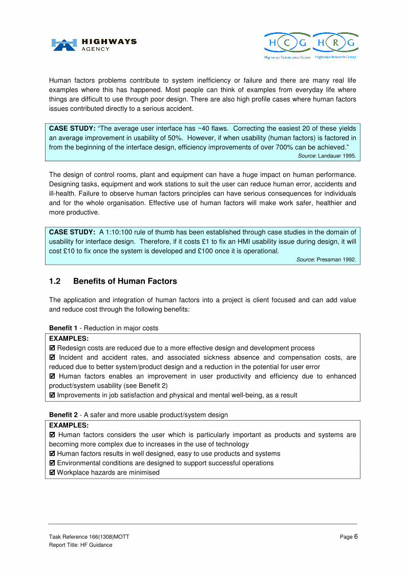
Human factors problems contribute to system inefficiency or failure and there are many real life
examples where this has happened. Most people can think of examples from everyday life where
things are difficult to use through poor design. There are also high profile cases where human factors
issues contributed directly to a serious accident.
CASE STUDY: “The average user interface has ~40 flaws. Correcting the easiest 20 of these yields
an average improvement in usability of 50%. However, if when usability (human factors) is factored in
from the beginning of the interface design, efficiency improvements of over 700% can be achieved.” Source: Landauer 1995.
The design of control rooms, plant and equipment can have a huge impact on human performance.
Designing tasks, equipment and work stations to suit the user can reduce human error, accidents and
ill-health. Failure to observe human factors principles can have serious consequences for individuals
and for the whole organisation. Effective use of human factors will make work safer, healthier and
more productive.
CASE STUDY: A 1:10:100 rule of thumb has been established through case studies in the domain of
usability for interface design. Therefore, if it costs £1 to fix an HMI usability issue during design, it will
cost £10 to fix once the system is developed and £100 once it is operational. Source: Pressman 1992.
1.2 Benefits of Human Factors
The application and integration of human factors into a project is client focused and can add value
and reduce cost through the following benefits:
Benefit 1 - Reduction in major costs
EXAMPLES:
���� Redesign costs are reduced due to a more effective design and development process
���� Incident and accident rates, and associated sickness absence and compensation costs, are
reduced due to better system/product design and a reduction in the potential for user error
���� Human factors enables an improvement in user productivity and efficiency due to enhanced
product/system usability (see Benefit 2)
���� Improvements in job satisfaction and physical and mental well-being, as a result
Benefit 2 - A safer and more usable product/system design
EXAMPLES:
���� Human factors considers the user which is particularly important as products and systems are
becoming more complex due to increases in the use of technology
���� Human factors results in well designed, easy to use products and systems
���� Environmental conditions are designed to support successful operations
���� Workplace hazards are minimised

Task Reference 166(1308)MOTT Page 7
Report Title: HF Guidance
Benefit 3 - Exploitation of established theories and methods that complement existing good project
management approaches
EXAMPLES:
���� Human factors ensures that tasks are within the physical and cognitive capabilities of operators
and maintainers
���� Human factors creates a systematic training and competency assurance process
���� Human factors creates information systems that ensure that communications are understood
1.3 Purpose of this document
The purpose of this guidance document is to summarise the best practice human factors approach to
system/product design and development, within the general project lifecycle, in order to provide
support to the Highways Agency in creating more cost effective and usable designs. The emphasis of
this document is specifically on Highways Agency control room design and development. However, it
should be noted that the underlying principles can be applied to the general design and development
context of any product or system.
This guidance should prove useful to both Highways Agency project sponsors/managers and human
factors specialists involved in Highways Agency system/product design and development projects:
• This guidance should provide Highways Agency project sponsors/managers with a good
introduction to the human factors considerations of a design and development project and allow
for the planning of such a project:
o At the very least, it should result in the Highways Agency project sponsor/manager having
a questioning attitude about the human factors on the project, and in the process,
creating a better designed system/product and a more cost effective design process
o If, upon reviewing the questions in Section 2, the project sponsor/manager decides to
engage a human factors specialist on the project, then this guidance can be used by the
project sponsor/manager as a checklist to ensure that the required human factors
activities are undertaken by the specialist and as a communication tool between the
project sponsor/manager and the human factors specialist in demonstrating Highways
Agency requirements for human factors input
• This guidance should prove to be a valuable reference to human factors specialists also, as it
can be used as a communication tool between the project sponsor/manager and the human
factors specialist in demonstrating Highways Agency requirements for human factors input
This guidance gives examples of the techniques and tools used to address human factors issues. It
should be noted that, depending on the level of competence and experience of the reader, many of
these techniques may require the skills of a human factors specialist to be carried out correctly. The
procedures in this document are also highly abbreviated and will only serve as an introduction to that
technique. The reader can find references at the end of each section if they require further
information. In addition, Appendix A summarises the best practice design and development
processes, including the general human factors approach to system design and the approach specific
to the design of control centres and control centre HMI.

Task Reference 166(1308)MOTT Page 8
Report Title: HF Guidance
1.4 Using this document
This document is structured in the following way:
Section 2 Provides a checklist to establish whether the guidance in this document is relevant to
the project
Section 3 Describes the essential steps that need to be followed to apply human factors to your
design and development process
A number of case studies and tips have been presented within the document. These have been
collected during the course of this work and are used to provide examples and context for the best
practice/methods that are described.

Task Reference 166(1308)MOTT Page 9
Report Title: HF Guidance
Section 2 - Is This Guidance Relevant To Your Project?
The flowchart below will help you to decide if the guidance in this document is relevant to your design
and development project and whether you may benefit from specialist human factors advice.
Consider the project that you are involved with and the outcome (e.g. design) that you are aiming to
achieve:
NB. This checklist will take you approx 5 minutes to
complete and its application could help you save costs
on the project via a more efficient design process and
through the creation of an enhanced end product.
START

Task Reference 166(1308)MOTT Page 10
Report Title: HF Guidance
• If you are at the very start of a project, it is appreciated that there may be a number of
questions where your answer is ‘unknown’; however, you are invited to review the relevant
sections of the guidance as prompted and revisit this checklist (and the associated guidance) at
each stage boundary/gateway on your project, to ensure that human factors are being managed
and included in your project as it develops
• If your project is well underway, e.g. you are at the detailed design stage or even more
advanced, it is not too late to apply this checklist and review the relevant guidance to improve the
human factors in your design
NB: The purpose of the questions presented in this checklist is to highlight the type of human factors
issues you should be considering on your project and the questions are in no way exhaustive. Each
design issue should be discussed with respect to the uniqueness of the task/project in order that
suitable trade offs and compromises can be made.
• Key question summary: Can this person …. With this training … Do these tasks … To
these standards … Under these conditions?
TIP: Definitions
User = a person who will be interacting with the product/equipment that you are designing, e.g.
an operator in an RCC using an interface.
Task = operational task conducted in RCC, etc.
System = computer based system that has a user interface in the RCC
Particular responses to the different questions in the checklist will refer you to different steps in the
guidance (presented in Section 3). To summarise, the guidance contains the following elements:
Step 1 - Clarify goals and requirements See page 17
Step 2 - Define operator tasks See page 20
Step 3 - Allocate tasks to the people or the technology/system See page 22
Step 4 - Define the task requirements See page 24
Step 5 - Design the job and work organisation See page 28
Step 6 - Test the initial design See page 31
Step 7 - Develop conceptual design See page 35
Step 8 - Test the conceptual design See page 36
Step 9 - Develop detailed design See page 37
Step 10 - Test the detailed design See page 42
Step 11 - Gather operational feedback See page 44
HUMAN FACTORS CHECKLIST: Have you considered these issues?

Task Reference 166(1308)MOTT Page 11
Report Title: HF Guidance
Response
Topic Area and Questions Yes No Unsure N/A
Pink Box = Action: see
relevant Step in
Section 3…
Staffing and Personnel Topics: Staffing levels, workload, team, organisation, job specifications, team
organisation, selection, recruitment and career development, qualifications and experience required, competence requirements, physical characteristics (body size, strength, eyesight, etc).
Will you define who your users are going to be?
1
Will the task require more than one person to complete it?
1, 2, 4
Will the task demand either a particularly high or a particularly low workload?
4
Will the users’ skill sets be considered?
1, 3, 5
Could the system have a negative impact on staff job satisfaction?
5
Will the system be designed to match the mental and physical abilities of users and maintainers?
1 - 5, 7, 9
Will the project outcome result in any changes to existing operational teams?
5
Training Topics: Developing and maintaining the required knowledge, skills and abilities to operate and maintain
the system, training documents and courses, training facilities, specialist training, etc. Will there be clear job descriptions that illustrate the tasks that will be undertaken?
5
Will users require specific training to use the product/outcome of your project?
1, 5
Will different competency levels be required? 5
Are you automating any part of the system? 4
Will there be a plan in place to effectively manage the transfer of skills? 4, 5
1. Review the checklist
questions below with respect to your project and the
product/equipment and/or operational task you are
developing
2. Any question that results in a pink box response requires the review and application of
at least one Step of the guidance
3. Refer to the guidance
(Section 4). The guidance can be read as a whole, or you can
focus on the sections of relevance as noted in this
column

Task Reference 166(1308)MOTT Page 12
Report Title: HF Guidance
Response
Topic Area and Questions Yes No Unsure N/A
Pink Box = Action: see
relevant Step in
Section 3…
Task Design Topics: Organisation changes, communication, task support, working arrangement, operator
tasks, automation and shifts. Will the impact of the new operational task be considered in relation to existing tasks and workload?
2, 3, 4
Will there be any tasks that are required to be performed in parallel? 2, 4
Will there be any time pressure put on the operators? 2, 4
Will there be any cumbersome or monotonous tasks? 2, 4
On completion, will the task require a review, e.g. by a peer, supervisor? 2, 4
Will the impact of the new operational task be considered in relation to existing tasks and workload?
2, 3, 4
Human Factors Engineering Topics: Equipment design, workstation design, workspace layout,
maintenance access, human characteristics, user interface design, allocation of function. Will it be clearly understood how the new product/equipment that you are developing in your project will be integrated with existing systems/equipment/operational tasks?
3, 4, 7, 9
Will the maintenance requirements be defined, and will they be examined to ensure they are they feasible?
2, 5
Will the design ideas of the displays, controls, software interfaces etc. be considered at an early stage of the design process?
4, 7
Will the operating environment change as a result of the implementation of this new system/product?
7, 9
Will best practice for the layout of the operating environment be identified and considered, e.g. to manage communications, tasks, etc.?
7, 9
Will the impact of the operator’s and team’s situational awareness, decision making and communication be assessed?
4, 5, 7, 9
Health and Safety Hazards Topics: Short or long term hazards to health resulting from normal operation,
of the system, e.g. exposure to toxic materials, electric shock, physical injury, musculoskeletal injury, working environments (e.g. climate, lighting, noise). Will the relevant health and safety standards be identified and considered?
1, 5
Will the range of environmental issues be considered in relation to task performance, e.g. temperature, lighting and noise levels?
5, 7, 9
Could there be risk of injury through use or maintenance of the system? 2, 5, 7, 9
Will any tasks require repetitive movements or heavy lifting? 2, 4, 7, 9
Will criteria be defined to manage the trade offs between health and performance?
4, 7, 9

Task Reference 166(1308)MOTT Page 13
Report Title: HF Guidance
Response
Topic Area and Questions Yes No Unsure N/A
Pink Box = Action: see
relevant Step in
Section 3…
System Safety Topics: How to avoid the safety risks which humans might cause by operating or maintaining
the system abnormally, sources of human error, effects of misuse or abuse and decision making. Will you consider how the system can support operator decision making activities?
4, 7, 9
In the event of an error will the system provide clear feedback to the operator?
4 - 10
Will the operator easily be able to correct the system if any errors are made?
4 - 10
Will the operator be required to respond to system alarms? 4 - 10
Could the safety of the related operating environments (e.g. motorway) be negatively affected as a result of this project?
4
Will you think about maintenance processes for the system and how the system will be safety returned back to service?
2, 4, 5
Organisation Topics: Organisational structure, team working, leadership, job description, communication and
training. Will the new system impact on how separate groups/teams of people interact with one another?
2, 4, 5
Will the system change be communicated to all levels of the organisation?
5, 7, 9
Will contractors be used to do any of the operational tasks? 5, 7, 9
Will changes to existing personnel plans and performance management systems be required?
5, 7, 9
Will the commissioning of your project outcome affect existing systems? 2, 4, 5
Thank you for completing the checklist.
If your response to any of the questions has resulted in the ticking of a ‘pink’ box, it is
recommended that you now review the relevant Step(s) in Section 3: Human Factors Guidance.
Are you going to review the relevant Step(s) of the Human Factors Guidance at this time?
If yes, please complete the form in Appendix F
If no, please complete this form in Appendix G
If none of your response to any of the questions has resulted in the ticking of a ‘pink’ box,
there is no requirement, at this stage, for you to review the Human Factors guidance. However, if you
feel it would assist your project you can review the Guidance steps in Section 3: Human Factors
Guidance.
Please complete the form in Appendix E
It is recommended that you revisit this checklist at each project stage boundary to reconsider the
need for human factors input and complete an additional form for the project file.

Task Reference 166(1308)MOTT Page 14
Report Title: HF Guidance
Section 3 - Human Factors Guidance
The best practice guidance is presented in 11 steps. The purpose of the guidance is to summarise
the best practice human factors approach to system/product design and development, within the
general project lifecycle, in order to provide support to the Highways Agency in creating more cost
effective and usable designs.
The guidance provides some simple steps that you can include within your project plan and supports
you in this through raising a number of questions for you to consider. The guidance can be read as a
whole, or you can focus on the sections of relevance.
• If you are at the very start of a project, it is appreciated that there may be a number of
questions where your answer is ‘unknown’; however, you are invited to review the relevant
sections of the guidance at each stage boundary/gateway on your project to ensure that human
factors are being managed and included in your project as it develops
• If your project is well underway, e.g. you are at the detailed design stage or even more
advanced, it is not too late to apply this guidance to improve the human factors in your design
Disclaimers:
• It is assumed that members of your project design team have some knowledge or
understanding of ergonomics/ human factors
• The guidance presented is high level and therefore significant human factors issues should
be discussed with the wider project teams
• There is no single way to tackle human factors issues; it always depends on the task and its
context, therefore this guidance should be used with caution
Each step within the guidance is presented in terms of what, why and how it can be undertaken and
the output that results from following the approach. Further sources of information are also provided.

Task Reference 166(1308)MOTT Page 15
Report Title: HF Guidance
Step 1 - Clarify goals and requirements
Step 1.1 - What? The purpose of this first step is to clarify operational goals, relevant requirements
and constraints associated with the design of control centre(s) and operational system interfaces.
The purpose and role of the control centre (e.g. descriptions and functions of the sub-systems, for
example process units, power systems, communications systems etc.), the control room and the
human machine interface (HMI) (e.g. control panel/interface purpose and functions) and their
relationships with other relevant sub-systems should be identified and documented.
TIP: Experience from existing or similar control centres can make a valuable contribution to
refurbishment or new projects and this experience should be given appropriate consideration at the
start of project.
Step 1.2 - Why? Clarifying the goals and requirements at the earliest stage in the design and
development process allows them to be used as a driver and to be constantly referred back to, to
ensure the project, and ensuing design, is on track to fulfil its purpose.
CASE STUDY: Regional Information Display Demonstrator (RIDD)
(This Highways Agency system was trialled in 2008 and remains available for use in certain areas)
Summary Description - The RIDD is a service for RCC operators that provides speed and journey-
time information across the South West and neighbouring RCC areas. The system also has the
capability to display details of incidents, road works and VMS settings on a graphical display of the
network. There are two ways of viewing information on the RIDD, these are, a regional view which
provides an overview of journey times, and a detailed view which shows actual speeds, local events
and Variable Message Sign settings. Although the system was only intended as a trial demonstrator,
the system proved so useful to RCC operators that they requested that the system remain installed
for continued use.
Human Factors Issues - Development of the RIDD involved input from Human Factors specialists.
The initial concept considered user requirements and the process followed involved an iterative
development approach which resulted in continuous design enhancements.
Step 1.3 - How? In order to fully understand and explore the purpose and the role of the control
centre/HMI, the project team will need to examine a range of human factors.
The characteristics of the users, tasks/activities and the organisational and physical environment
define the circumstances in which the system is (to be) used. Therefore, it is important to identify and
understand the details of the circumstances so as to guide early design decisions, and to supply a
basis for evaluation. Information should be gathered about the context of use of new products and
systems. The context in which the system is to be used should be identified in terms of:
• The intended users
o Knowledge, skill, experience, education, training, physical attributes, habits,
preferences and capabilities (for different user groups or different roles)
• The tasks/activities the users are to perform

Task Reference 166(1308)MOTT Page 16
Report Title: HF Guidance
o Frequency and duration of performance, implications for health and safety (use of
personal protective equipment etc.) – this process should consider normal, unusual
and emergency conditions/tasks
• The environment in which the users are to use the system
o Hardware, software, materials to be used, relevant standards1, regulatory guides,
attributes of the wider technical environment, the physical environment, the ambient
environment, the legislative environment, and the social and cultural environment.
What feedback is available from existing similar contexts/control rooms so that you
can learn from previous mistakes?
TIP: A range of stakeholders, e.g. potential/current operators, managers, maintenance teams, should
be involved to ensure that as much relevant information is captured as possible.
Several techniques can be employed to elicit the requirements from stakeholders, e.g. contextual
interviews, focus groups (requirements workshops), and checklists. Where necessary, a combination
of these methods can be employed to establish the exact requirements of the stakeholders, so that a
system that meets the user and organisational needs is produced.
The product of this activity should be a ‘context of use description’, a working document that contains
a description of the relevant characteristics of the users, tasks and environment which identifies what
aspects have an important impact on the system design. Additionally, any requirements or
constraints to be taken into account in the design of control centres should be identified and
documented. The description should:
• Specify the range of intended users, tasks and environments in sufficient detail to support
design activity
• Be derived from suitable sources
• Be confirmed by the users or, if they are not available, by those representing their interests in
the process
• Be adequately documented
• Be made available to the design team at appropriate times and in appropriate forms to
support design activities
An example of attributes of a ‘context of use description’ is provided in Appendix H.
Operational feedback from other projects should be incorporated (Step 11 - Gather operational
feedback) and any conflicting requirements (there are usually several!) should be documented,
evaluated and resolved. Those issues that cannot be resolved should be placed on an Issues Log
(see Appendix I for an example) and monitored to ensure that they are dealt with at a suitable point in
the design lifecycle before they have chance to cause a bigger (and more expensive) problem later
down the line in the design process.
1 See Appendix J for a list of relevant human factors and ergonomics standards that might be
relevant to your design.

Task Reference 166(1308)MOTT Page 17
Report Title: HF Guidance
Step 1.4 - Outputs? The outputs for this task include a common set of user and organisational
requirements (context of use description) that incorporates:
• A statement of operational goals (e.g. what the system’s functions should be);
• Relevant requirements and constraints;
• Conflicting requirements and solutions of compromise.
…PLUS - any issues/uncertainties/problems should be documented in the Issues Log.
This common set of user and organisational requirements can thereafter be used to validate that a
design fulfils its needs.
Step 1.5 - Want more information? Review the following:
ISO 13407 (1999). Human-centred design processes for interactive systems. International Standard,
International Organization for Standardization. Available at: http://www.bsigroup.com/
Context of use analysis. Available at: http://www.usabilitybok.org/methods/context-of-use-analysis
Usability context analysis: a practical guide. Available at:
http://www.usabilitynet.org/papers/UCA_V4.04.doc

Task Reference 166(1308)MOTT Page 18
Report Title: HF Guidance
Step 2 - Define operator tasks
Step 2.1 - What? Based on the findings of Step 1, a high level task analysis should be carried out
and documented. This means considering what the key, high level tasks are that need to be
undertaken to achieve the goals and requirements documented in Step 1.
Step 2.2 - Why? This step is conducted as a first action in understanding what key tasks are
required to achieve the objectives defined in Step 1, before these tasks can be appropriately designed
to be conducted as efficiently and safely as possible.
CASE STUDY: Adaptive CCTV (being trialled across parts of the network)
Summary Description - The Highways Agency has been trialling ACCTV to assist operators in the
WMRCC to monitor a stretch of motorway. The ACCTV system is a computer algorithm that operates
with the CCTV system to automatically detect incidents and abnormalities on the road. The system is
capable of detecting abnormalities such as, debris, pedestrians and broken down vehicles. It is
intended that the system provides an early warning notice to operators, and highlights suggested
CCTV images that the system has detected an incident in.
Human Factors Issues - Operators face many screens and are expected to interact with many
systems – human factors consideration should be given to the way in which alarms and early warning
notices are presented to operators. There may be a reduction in vigilance amongst CCTV operators
as a result of reliance on the system. The operator needs confirmation that the ACCTV is active –
even when no incidents are detected – so that they are confident that the system is operational.
Step 2.3 - How? The analysis may be undertaken by several methods, e.g. functional breakdown,
flow charts, simulations and operational walk-throughs (if you have this level of detail at this early
stage). The scope of the analysis shall include all anticipated operational modes of the controlled
system, e.g. what tasks need to occur during:
• Normal state of operation, from start up, usual operation, to shut down
• Emergency/abnormal operation
o E.g. what happens after an emergency/abnormal operation, because such operations
may impose temporary function/task allocation changes, special safety
considerations, job redefinition and environmental changes?
• Maintenance (scheduled as well as unscheduled)
o E.g. what happens when some or all of the systems’ process equipment, machinery,
displays and controls, utilities, etc. are unavailable due to maintenance activity?
The tasks should be documented in a simple list format, see Figure 2. Anything that is uncertain at
this early stage should also be noted on the list to ensure that it is not forgotten later down the line in
the design and development process.

Task Reference 166(1308)MOTT Page 19
Report Title: HF Guidance
Operator task: Responding to a call from an ERT (emergency roadside telephone)
1. Telephone rings at operator workstation
2. Operator answers call – via touch screen and headset?
3. Operator obtains details of incident – specific protocol for this needs to be defined
4. Operator logs details of incident – need to make sure software allows easy interaction
5. Operator checks location on map – define how this can be done through automation of the system
6. Operator actions the response
Figure 2 Example of a basic task list and issues to be defined.
Step 2.4 - Outputs? A list of high level tasks associated with the overall operational goals and sub-
goals.
…PLUS - any issues/uncertainties/problems should be documented in the Issues Log.

Task Reference 166(1308)MOTT Page 20
Report Title: HF Guidance
Step 3 - Allocate tasks to the people or the technology/system
Step 3.1 - What? The high level tasks identified in Step 2 should now be allocated to people
(operators) and/or machines (system/technology).
Step 3.2 - Why? This step is conducted so that a preliminary decision can be made about which
tasks are going to be undertaken by people and which by the machine/system (or a combination of
the two), in order to work to the strengths and characteristics of these two different system
components. For example, machines are far more suitable for routine monitoring tasks and for high
accuracy/repetitive tasks. However, people are much better suited to tasks that require adaptation,
strategy and planning.
CASE STUDY: NASS - Network Active Traffic Management Supervisory Subsystem
(Highways Agency system in development)
Summary Description - This system aids operators to make tactical decisions for controlling the
motorway. It works by collecting real time traffic flow data detected by roadside sensors, and
compares it to previously modelled data of traffic patterns. The NASS analyses the comparison of the
two sets of data and attempts to predict when flow breakdown, i.e. congestion is likely to occur. The
system prompts an RCC operator that it senses congestion building, and offers a number of solutions
to the operator to take action to alleviate the current situation. The system provides options on the
best course of action for a defined traffic management tactic, based on past data.
Human Factors Issues - The system is designed to perform much of the ‘donkey work’ (e.g.
monitoring traffic flow against modelled data), alerting the operator when decisions need to made.
Therefore, the strengths of the person and the machine (system) have been taken into consideration;
this design enables the operator to focus on more tactical tasks whilst the system performs the
mundane, repetitive tasks.
Step 3.3 - How? Initial allocation of function between equipment and humans or a combination of
these, should be carried out taking into account the respective capabilities of humans and machines
for given task requirements. This initial allocation of function should then be reviewed and confirmed
using detailed task analysis (see Step 4) as the design progresses. This will ensure that a systematic
approach is adopted that will enable the identification of impacts of allocating a function or task to a
human, machine or both and at both the single and complete system level.
TIP: It should be noted that these function allocations are subject to change as more detail is
developed during the design and a greater understanding is subsequently provided about the
allocated tasks.
The most suitable allocation of functions between the operator and machine should be decided after
considering the requirements of the task and environment and the strengths and limitations of both
the human and machine in this context. Preliminary allocation of function by designers should be
based upon the relative strengths and weaknesses of human and machine including:
• Physical workload
• Strength
• Repetition and duration

Task Reference 166(1308)MOTT Page 21
Report Title: HF Guidance
• Precision and vigilance requirements
• Environmental conditions
• Commercial and any other pressures
Overall co-ordination of tasks will also be required and each operator should have clearly defined
roles and responsibilities where functions are allocated to them.
Step 3.4 - Outputs? These should include:
• Sets of functions (tasks) that are anticipated to be performed by people (operators)
• Sets of functions (tasks) that are anticipated to be performed by the technology/machines,
and associated requirements for error-tolerant technology/machine design
• The interactions between humans and technology/machines
…PLUS - any issues/uncertainties/problems should be documented in the issues log.
Step 3.5 - Want more information? Review the following:
Dearden, A., Harrison, M & Wright, P (2002). Allocation of function: scenarios, context and the
economics of effort. International Journal of Human-Computer Studies,
Volume 52, Issue 2, February 2000, Pages 289-318. Available at:
http://homepages.cs.ncl.ac.uk/michael.harrison/papers/deardenhw99.pdf
Function allocation. Available at: http://www.usabilitybok.org/methods/function-allocation

Task Reference 166(1308)MOTT Page 22
Report Title: HF Guidance
Step 4 - Define the task requirements
Step 4.1 - What? A task analysis should be conducted to examine the basic elements of the tasks
that have been allocated to people during Step 3. The task analysis can include notes on
(preliminary) design/engineering solutions based on prior experience or on opportunities for
innovation and invention that may be identified.
TIP: It is acknowledged that only limited information about these task elements may be available at
this early stage in the design and development process. Therefore, the project team should
document what they can and add to the task analysis as more information becomes available.
Step 4.2 - Why? The process will capture information relating to what people will do when carrying
out their tasks/jobs to enable the project team to consider any design issues that might need rectifying
at an early stage. This step is conducted to ensure, very early on in the design and development
lifecycle, that the basic, early ideas about the tasks are achievable by the users and that any
fundamental problems are captured so that they can be managed appropriately. The outcomes of
task analysis can help to:
• Define selection criteria for operators (e.g. operator skills and abilities)
• Identify training requirements
• Develop good procedures
• Determine the best layout for equipment
• Estimate the number of staff required for a job
• Estimate workload
• Investigate human error
• Make recommendations for improvement
TIP: Applying task analysis methods can be complex. You may need some specialist help to carry
out the analyses.
Step 4.3 - How? There are two widely used methods of task analysis. The section illustrates when it
would be appropriate to follow these techniques by referring to a control room case study scenario:
SCENARIO: The project team want to design a new control room interface that enables
operators to open the hard shoulder for use as a running lane. They want to know the best
way of integrating this with existing systems and to find out whether the task is achievable or
not with the time, personnel and resources available.

Task Reference 166(1308)MOTT Page 23
Report Title: HF Guidance
At the concept stage (and earlier) in the project, it is likely that very little detail will be available about
what the interface will look like or how the task will be undertaken, which is appropriate as the task
design should be driven by the requirements and not ‘set in stone’. Therefore, a hierarchical task
analysis is appropriate, see Figure 3. This sets out in a clear structure, what each step of the task
involves. Starting at the top, the first box specifies the overall task goal i.e. in the example provided –
opening the hard shoulder. The next layer of boxes break down the goal into discrete steps, or sub-
goals.
Figure 3 Example of a basic hierarchical task analysis.
In this example scenario, as it is a new concept and since this particular task has not been attempted
before, there is no ‘system expert’ to take the team through the specific steps. However, lessons can
be learnt from similar tasks and experiences. Therefore, it is appropriate for the team to discuss the
proposed task with some experienced control room operators, and from this put together a basic
procedure. They can then draw up a basic list of actions and ‘walk through’ the task.
TIP: This section provides you with an introduction to some of the basic skills needed to conduct an
analysis, but you are strongly recommended to read further about the techniques you intend to use,
and to attend a training course in this subject.
Breaking down task descriptions into increasing levels of detail should continue until the project team
are satisfied that they understand the task completely (which may not be possible early on in the
design process, more details should be added as they become available). Notes are usually added to
clarify the information, for example, to indicate sequences of operation. The ‘tree’ format can get very
wide and difficult to fit on one page. An extract from the same task analysis is shown in the
alternative, ‘tabular’ format below, Figure 4. Note that more task details can be included in this format.
1.2 Activate
opening
1.1.2 Review
images
1.1.1 Locate
CCTV
1.1.3 Set
signs
1.1 Prepare
for opening
1. Open hard
shoulder
1.1.5 Press
button Y
1.1.4 Press
button X
1.1.6 Press
button Z
[P
2.5.1.1.2 2.5.1.1.3 2.5.1.2.1 2.5.1.2.2 2.5.1.2.3

Task Reference 166(1308)MOTT Page 24
Report Title: HF Guidance
Task
Step
Potential
errors
Consequence
of error
Task
support
Recovery
opportunities
Recommendations/
Solutions
1.1 Prepare for opening.
1.1.1
Locate
CCTV.
Identify the
incorrect CCTV
image.
Operator unable
to view the
appropriate
hard shoulder.
Operator may
think hard
shoulder is clear
when the
incorrect CCTV
is being viewed.
Procedures /
manuals.
Training.
Camera
location and
ID on video
image
Operator
realises that
CCTV needs to
be viewed.
Operator
realises that
wrong CCTV
image has
been selected.
Ensure feedback is
provided to the
operator for CCTV
image selection (e.g.
onscreen identifiers).
Ensure an additional
task step is included so
that the operator has to
confirm the location of
the CCTV image
against the hard
shoulder location.
Figure 4 Example of a tabular task analysis structure.
As a minimum the following should be recorded in columns in a tabular task analysis:
• Potential errors and violations
• Consequence of human failure
• Task support, e.g. interfaces & equipment; environment; procedures; training; supervision
• Recovery opportunities (if an error is made)
• Recommendations/solutions for the design
You may also want to consider the following elements of the task steps:
• Manual and cognitive activities
• Task frequency, duration and complexity
• Communication requirements
• Environmental conditions
When a task is time dependent, the following columns may be added to the tabular task analysis:
• Time available
• Estimated time required to successfully complete the task
Where there are potential concerns about organisational and management issues then the following
should also be considered. These are likely to be considered at the task goal level rather than in
relation to individual task steps, as management and organisation features tend not to vary at the sub
task level, but influence the task as a whole:
• Allocation of function
• Task Characteristics (frequency, duration, repetition, physical & cognitive demand)
• Type of supervision

Task Reference 166(1308)MOTT Page 25
Report Title: HF Guidance
• Task planning and workload
• Competency assurance and training
• Safety Management Arrangements
Conducting a task analysis gives the project team invaluable insight into the proposed task. Further
task analysis techniques can be applied to gather more information on aspects of a task:
• Timeline analysis - used to estimate the time taken to complete a task
• Link analysis - used to show the number of links (communications links or movements
between different parts of a plant) required to achieve a task
Step 4.4 - Outputs? The output will include a flow diagram or a table (See Step 4.3 above) that
presents a clear summary of peoples' task goals, the order in which they must take place, and an
indication of any constraints relevant to the different sub-tasks.
…PLUS - any issues/uncertainties/problems should be documented in the Issues Log.
Step 4.5 - Want more information? Review the following:
Kirwan B and Ainsworth L K (Eds), 1992, 'A Guide to Task Analysis'. Taylor and Francis: London.
Available at: http://www.taylorandfrancis.com/books/details/9780748400584/
Stanton, N. A., Salmon, P. M., Walker, G. H., Baber, C. & Jenkins, D. P (2005). Human Factors
Methods: A Practical Guide for Engineering and Design. Ashgate: Aldershot. Available from:
http://www.ashgate.com/default.aspx?page=637&calcTitle=1&title_id=8082&edition_id=9199
Hierarchical task analysis. Available at: http://www.uxmatters.com/mt/archives/2010/02/hierarchical-
task-analysis.php
Task analysis. Available at: http://www.usabilitynet.org/tools/taskanalysis.htm
Contextual task analysis. Available at: http://www.usabilityfirst.com/usability-methods/contextual-task-
analysis/

Task Reference 166(1308)MOTT Page 26
Report Title: HF Guidance
Step 5 - Design the job and work organisation
Step 5.1 - What? After the tasks have been examined, job design is then undertaken. This means
that the tasks that have been allocated to people during Step 3 are examined alongside the user
requirements (e.g. policy for work organisation) and any regulatory requirements (e.g. requirements
for work organisation, i.e. hours of operation), identified during Step 1. This enables tasks to be
assigned to particular roles according to the planned work organisation.
Step 5.2 - Why? In order to reduce the opportunity for error and retain a motivated workforce, the job
design process should enable the operators’ physical characteristics, cognitive and analytical abilities,
and the organisational context, to be considered so that the job design can be modified accordingly.
CASE STUDY: On-off button for lighting - Midnight switch-off
(in operation across parts of the Highways Agency network)
Summary Description - This is an initiative by the Highways Agency to reduce carbon emissions and
light pollution by turning off selected road lighting after midnight. During times of low volume traffic,
some motorways deemed to be suitable are selected to operate with illumination turned off in the
early hours of the morning. The switching off of motorway lighting is carried out by timing devices at
the road side, however RCC operators are provided with a push-twist type override button to enable
them to turn the lights on if required. During the trial, the decision about which lights to switch off and
where this would be managed from was governed by time of day and current traffic flow rates. A
push-twist type switch was mounted on an operator desk in a local RCC, and used to turn off the
selected lighting.
Human Factors Issues - Some human factors considerations to prevent accidental activation of the
switch had been given due to the multiple actions required to depress the switch. However no
feedback was provided to the operator to confirm if the action of pushing the switch had actually
resulted in the intended outcome. The only way verification could be achieved was to carry out a
check using the CCTV system. Applying best practice human factors principles would highlight the
benefits of providing feedback to an operator.
Step 5.3 - How? The first thing to do is to prepare a preliminary work organisation structure that
satisfies user and regulatory requirements. Consider:
• Team structure (number of people and skills/abilities)
• Lines of responsibility (line management)
• Workplace culture
• Union/management arrangements
• Communication requirements
After documenting a preliminary work organisation structure, conduct a job design assessment:
• Define a set of job assignment criteria; this should include criteria/job features that can be
considered when assigning tasks to particular roles (people), e.g. workload, job sharing,
information and data requirements, required tools/facilities/desk space etc.
• Determine jobs that are going to be carried out by each operator

Task Reference 166(1308)MOTT Page 27
Report Title: HF Guidance
The types of questions to consider whilst designing the work organisation structure and job/s include:
• What are the Highways Agency policies, and UK/EU rules, regulations and best practice that
you need to abide by when designing the job roles? These should have been identified
during the user requirements step (Step 1)
• What operational tasks need to be conducted by operators? These should have been
identified during Step 4
o Which tasks are related and might be appropriate to be undertaken by a particular
individual?
o Which tasks will be conducted most frequently?
o What skills, abilities (physical and mental) and knowledge are required to do the
tasks?
o What are the requirements for training?
o What are the requirements for operating procedures?
o What information/task support is needed to conduct the tasks?
• What work organisational structure suits the policies/rules/regulations/best practice and the
tasks?
o What are the operators’ individual needs for job satisfaction?
o Will there be scope for personal growth/career progression?
• What are the communication requirements (e.g. between operators, control rooms and control
centres)?
o Which people need to communicate?
o How frequently do they need to communicate?
o What’s the best method for communicating?
o If you are introducing new communication methods/equipment…
� …how are users going to be trained?
� …what are the maintenance issues?
TIP: Job design is an iterative process which may require several iterations as the design develops to
manage all the human and organisational issues that need considering.
5.4 - Outputs? These should include:
• The work organisation (structure and number of operators, lines of reporting)
• The jobs that are assigned to each operator
• Requirements for communications between operators, between control room and local control
centres
• Requirements for operating procedures
• Requirements for training
• Requirements for information and control

Task Reference 166(1308)MOTT Page 28
Report Title: HF Guidance
Step 5.5 - Want more information? Review the following:
Parker, S.K & Wall T.D (1998). Job and Work Design: Organizing Work to Promote Well-Being and
Effectiveness (Advanced Topics in Organizational Behavior). Sage Publications.
Reason, J & Hobbs, A (2003). Managing Maintenance Error: A Practical Guide. Ashgate, Aldershot.
Available from:
http://www.ashgate.com/default.aspx?page=637&calctitle=1&pageSubject=451&pagecount=4&title_id
=70&edition_id=160
Smart working: the impact of work organisation and job design. Available at:
http://www.cipd.co.uk/subjects/corpstrtgy/orgdevelmt/_smrtwrkgri.htm
The process & content of job & work organisation (re)design. Available at:
http://www.moderntimesworkplace.com/Work_Redesign_Guide.pdf

Task Reference 166(1308)MOTT Page 29
Report Title: HF Guidance
Step 6 - Test the early design ideas
Step 6.1 - What? Early and regular testing of the design ideas/design concepts that have been
developed to date, against the goals and requirements, is key to ensuring that the user is provided
with usable interfaces and a suitable working environment.
• Verification exercises should show whether something is designed to meet the requirements
and answer the question – “Does it meet the original system specification?”
• Validation exercises should show whether something is effective and answer the question –
“Does the system work?”
TIP: The verification and validation activities should be an integral and continuous part of the design
process, done as early as possible to allow modifications to be made, and conducted prior to each
project gateway.
Step 6.2 - Why? This step is conducted to ensure that the user is provided with usable interfaces
and a suitable working environment and that any ‘hidden’ or unanticipated problems can be realised
and managed at a very early stage in the design process. If conducted appropriately and at an early
stage, this process can save significant time and effort (and money) over the lifetime of the project.
Step 6.3 - How? There are a number of ways of testing a design, depending on how advanced the
design is (e.g. concept, detailed design), what aspects of the design you wish to evaluate or verify,
how much time/money you have, and how detailed you want to be, e.g.:
• Check (verify) design features against the original design criteria to ensure compliance
• Evaluate (validate) functions and usability through the application of heuristic (“rule of thumb”)
evaluation
• Conduct link analysis and/or time-line analysis to evaluate:
o Traffic patterns and communication links (i.e. for control suite design)
o Communication and coordination tasks (i.e. for control room design)
• Conduct walk throughs of scenarios or task sequences to ensure designs are suitable for
tasks
• Use basic representations of the new design and involve users to test them out, e.g.:
o Drawings
o Photographs
o Mock ups
o Virtual reality
Whatever method is chosen, a number of steps need to be followed to evaluate a design:
NB. This section focuses on the perspective of evaluating the usability of a computer interface.

Task Reference 166(1308)MOTT Page 30
Report Title: HF Guidance
TIP: The design of the HMI is probably the stage of development where human factors specialists
work most closely with engineers and designers. The role of human factors in relation to HMI design
is to provide information regarding the human performance implications of the various design
alternatives. This involves the process of human performance testing, analysing and interpreting the
human performance data, and conducting in-depth evaluations of suggested designs.
A. Determine the test statements(s)
The test statement(s) determines the focus for testing, the required participants, the test tasks
and the measures that will be taken. Test statements can be informed by:
• Characteristics of the intended user group or groups;
• Usability or design goals defined as outputs of the requirements review (Step 1);
• Business or corporate objectives, e.g. product comparisons.
Usability can also be defined by three dimensions which include effectiveness (the accuracy
and completeness with which users achieve specified goals as measured by the number or
proportion of tasks successfully completed); efficiency (the resources expended in relation to
the accuracy and completeness with which users achieve goals as measured in time, money,
or effort e.g. key strokes) and satisfaction (the comfort and acceptability of use as measured
by attitude scales, perception in relation to enjoyment, fun, frustration and other indicators
such as health problems). Once the test statements have been defined in general terms they
are redefined in ways that can be measured. The following examples are typical of
measurable usability statements2:
Example test statements associated with user characteristics
• 80% of users with a high-school (GCSE equivalent) education, 90% of users who have completed
high school (A Level equivalent) and 95% of users with a higher education degree will be able to
complete task A within ‘x’ minutes after no more than three attempts (efficiency);
• 90% of all users will be able to complete all tasks with no more than three errors on their first
attempt (effectiveness);
• 90% of all users will rate their level of frustration using the interface at less than 3 on a 5-point
Likert scale (satisfaction).
Example test statements associated with design goals
• All users will be able to find Y information within 1 minute on 90% of occasions (efficiency);
• All users will be able to complete task B without training. (effectiveness);
• 90% of users indicate that they would recommend interface A as opposed to its competitor to a
friend (satisfaction).
Example test statements associated with the Highways Agency’s objectives
• All users will be able to complete task C without error using either product (one is more expensive
than another, for example) (effectiveness). 2 It should be noted that these statements will be relevant only when there is some aspect of
the HMI that has been designed and communicated, which could be as basic as a sketch or as
detailed as a prototype.

Task Reference 166(1308)MOTT Page 31
Report Title: HF Guidance
• All users will be able to complete task D at least 5 seconds faster using the new product
compared to the old (efficiency).
• 70% of users indicate that they would be prepared to pay £xxxx.xx to own this software given
their current salary (satisfaction).
B. Choose the task scenarios
Task scenarios are based on the purposes for which the application is to be implemented in relation
to the relevant user group(s), the context of its use and with reference to design or usability goals. In
addition, three criteria can be used to select test tasks: typicality or representativeness; criticality or
risk; and the potentially problematic. Typical tasks are those that a majority of users will execute for
the majority of their time. Critical tasks are those for which the consequence of error may be
catastrophic. Potentially problematic tasks are those that may be associated with idiosyncratic
interface design. For all selected tasks the ‘ideal’ or optimal task completion sequence should be
defined in advance.
C. Select test participants
Test participants should represent the group or groups for whom the application is intended. The
objective in participant selection is to reduce variation associated with user characteristics so that
results can be interpreted with respect to the user interface rather than being confounded by
participant differences, for example, by age, education level, computer experience. Results from the
requirements stage (Step 1) can assist in defining important user groups.
D. Test context and materials
Ideally, usability testing should occur in a setting where extraneous variables associated with
environmental factors can be controlled, e.g. in a laboratory. Within this environment data collection
ranges on a continuum from observer-based manual data collection to data collection via highly
instrumented simulators.
E. Data collation and analysis
The purpose of usability testing is:
a) To assess the usability of a product
b) To identify and classify design defects
Thus data is typically collated at two levels of analysis for each scenario or across all scenarios if they
are of comparable complexity. At the first level, global indicators of usability are calculated in terms of
efficiency (task time), effectiveness (errors, task completion) and satisfaction (results of post-test
interviews or surveys). Where research questions specify targets, mean indicators facilitate an
assessment of how ‘far’ the application is from its ideal usability state.

Task Reference 166(1308)MOTT Page 32
Report Title: HF Guidance
TIP: If you are engaging a supplier/contractor to build a product you may wish to consider
implementing the following suggestions to ensure the supplier’s design meets the project’s human
factors requirements:
- Ensure the supplier has an integrated project team that understands and applies human factors
principles, e.g. specify human factors best practice standards that the supplier must adhere to (see
Appendix J for suggestions);
- Ensure that gateway reviews/fail-gates/system readiness checks include human factors verification
and validation activities;
- Consider having a human factors specialist involved on a call-off basis to check that the design is
appropriate from a human factors perspective.
Step 6.4 - Outputs? Approved initial design specifications and an improved design.
Step 6.5 - Want more information? Review the following:
Stanton, N. A., Salmon, P. M., Walker, G. H., Baber, C. & Jenkins, D. P (2005). Human Factors
Methods: A Practical Guide for Engineering and Design. Ashgate: Aldershot. Available from:
http://www.ashgate.com/default.aspx?page=637&calcTitle=1&title_id=8082&edition_id=9199
Rating scales for usability problems. Available at:
http://www.useit.com/papers/heuristic/severityrating.html
First principles of interaction design. Available at: http://www.asktog.com/basics/firstPrinciples.html
How to conduct a heuristic evaluation. Available at:
http://www.useit.com/papers/heuristic/heuristic_evaluation.html
Formative evaluation. Available at: http://www.usabilitybok.org/methods/formative-evaluation
Heuristic evaluation. Available at:
http://www.usabilitybok.org/methods/p275

Task Reference 166(1308)MOTT Page 33
Report Title: HF Guidance
Step 7 - Develop conceptual design
Step 7.1 - What? The purpose of this step is to develop and compare some concept design ideas,
taking on board the human factors and requirements explored so far. The features of the conceptual
design of a control room environment that are particularly important to consider from a human factors
perspective include:
• Layout of the control room
• Individual workstation layout and dimensions
• Choice of displays and controls
• Information and data flows
• Special security and access controls
• Environmental conditions and control
• Operation and management systems
• Communications and information links
The conceptual design phase is characterised by comparative evaluation of numerous alternative
design concepts potentially reaching the design requirements.
Step 7.2 - Why? The development (and evaluation) of concept designs is a key part of the design
process and is essential to enable good decisions to be made about the final design specifications.
CASE STUDY: Co-operative Vehicle Highway Systems (current research)
Summary Description - The future of motorway driving is expected to see an increase in
communication, e.g. electronically between the road and the vehicle. The Highways Agency is
researching technology to enable this communication to happen. The ultimate vision is for road signs
and information signs to no longer exist in a physical form, and instead be presented to the driver by
means of an electronic in-vehicle device.
Human Factors Issues - Human factors play a significant role in the way in which the information is
presented to the driver, e.g. text type, size, font, menu structures, quantity of information, alarm
format, to reduce distraction and enhance usability. The way in which the RCC operators’ tasks or
interfaces may change as a result of this proposed change in technology need to be considered, e.g.
the different human machine interfaces that might be used to set the message signs, the frequency of
the message setting, the way in which the information is presented within the vehicle etc.
Step 7.3 - How? Design specifications should be developed by reviewing the human factors
requirements and system requirements explored so far. In addition, design policy, e.g. Highways
Agency device selection policy, should be considered.
Step 7.4 - Outputs? These include several design ideas that can be taken forward for evaluation
and review to ensure they meet the design needs.
Step 7.5 - Want more information? Review the following:
What is design? Available at: http://www.usabilitybok.org/design/p286

Task Reference 166(1308)MOTT Page 34
Report Title: HF Guidance
Step 8 - Test the conceptual design
Step 8.1 - What? The conceptual design phase is iterative in nature, therefore several design
concepts can be developed and tested against the requirements, then revised, reevaluated, etc. until
one or more satisfactory concepts is achieved.
TIP: Lots of compromises will be made during the design and development process. Many aspects
need to be considered in the design and each major design decision and compromise should be
documented to enable verification and validation.
Step 8.2 - Why? This step is conducted to ensure the design achieves its ambitions. For further
explanation, see Step 6.
Step 8.3 - How? There are a number of ways of testing a conceptual design depending on what
aspects of the design you wish to evaluate or verify, please see Step 6 for details.
Common methods used to test the concept design ideas include:
• Scenario “talk-throughs”
• Scenario “walk-throughs”
• Interface simulations, for example team working, mock-ups
• Computer visualisation and animation studies
• Standards compliance audit
Step 8.4 - Outputs? Approved concept design specifications and an improved design.
Step 8.5 - Want more information? Review the following:
Stanton, N. A., Salmon, P. M., Walker, G. H., Baber, C. & Jenkins, D. P (2005). Human Factors
Methods: A Practical Guide for Engineering and Design. Ashgate: Aldershot. Available from:
http://www.ashgate.com/default.aspx?page=637&calcTitle=1&title_id=8082&edition_id=9199
Rating scales for usability problems. Available at:
http://www.useit.com/papers/heuristic/severityrating.html
First principles of interaction design. Available at: http://www.asktog.com/basics/firstPrinciples.html
How to conduct a heuristic evaluation. Available at:
http://www.useit.com/papers/heuristic/heuristic_evaluation.html
Formative evaluation. Available at: http://www.usabilitybok.org/methods/formative-evaluation
Heuristic evaluation. Available at:
http://www.usabilitybok.org/methods/p275

Task Reference 166(1308)MOTT Page 35
Report Title: HF Guidance
Step 9 - Develop detailed design
Step 9.1 - What? This step enables the development of detailed design specifications that are of
sufficient detail to be used to plan the construction of the control centre, and initiate requests for
tenders from suppliers. The features of the detailed design of a control room environment that are
particularly important to consider from a human factors perspective include:
• Control suite arrangement
• Control room layout
• Workstation layout and dimensions
• Design of displays and controls
• Environmental design
• Operational and managerial requirements
NB. The focus of this part of the guidance is on the detailed design of displays and controls.
TIP: HMI is an essential element contributing to users’ performance. Both standardisation and
legislation play an important role in the design of HMI at national, European and at international level.
However the constant proliferation of new functions and new devices may jeopardise the user
performance and system safety when devices are misused intentionally or unintentionally due to their
poor HMI.
Step 9.2 - Why? This step is conducted to enable detailed design specifications that are of sufficient
detail to be used to plan the control centre’s construction and initiate requests for tenders from
suppliers.
CASE STUDY: Autonomous VMS Switching from Positional Information of Gritters
(Highways Agency proof of concept completed)
Summary Description - When gritting vehicles were deployed, RCC operators would manually set
Variable Message Signs to display a warning to road users that gritting vehicles were in operation.
RCC operators tended to blanket cover a large area with the warning when the gritters were
operating. Due to the widespread warning, this proved to be a nuisance to drivers who observed the
warning signs but saw no gritters. In addition, the drivers would lose trust in the VMS display
information and begin to ignore them, the opposite of what is desired by the Highways Agency. The
display of “Gritting in progress” messages has now been automated by the use of GPS units attached
to each gritting vehicle. The on board GPS unit communicates with the Variable Message Signs so
that the signs only display the gritting message when appropriate, i.e. the gritting vehicle is within a
predetermined distance of the message sign.
Human Factors Issues - The public’s opinion of the reliability of information provided by message
signs will increase, therefore, it is likely that road users will modify their behaviour in accordance with
the message information displayed. In addition, due to the automation of the messaging, there is no
requirement for the RCC operators to spend time on the mundane task of creating “Gritting in
progress” messages and subsequently monitoring gritter location and removing messages as
necessary, reducing the scope for error.

Task Reference 166(1308)MOTT Page 36
Report Title: HF Guidance
Step 9.3 - How? The following aspects of the control room design need to be developed in detail,
based on the information gathered during the earlier steps, plus additional human factors questions,
knowledge and standards:
• Control suite arrangements - reconsider the system functions, operator tasks and job roles
and use this information to specify the workplaces and other areas within the control suite:
o What zones/areas are required in the control suite e.g. control rooms, equipment
rooms, rest areas, training rooms, offices, maintenance areas etc.?
o What tasks and jobs are going to be conducted in the different areas of the control
suite?
� How many people will be in each area/room?
� How many workstations will be required?
� Where will handovers and team briefings occur?
� What about filing and storage facilities for frequently required
documents/equipment?
� What space allowances do you need to make for future growth/modification?
o What interaction/communication/accessibility is required between the different areas
of the control suite?
� Consider who needs to access different areas (e.g. police, RCC staff) and
what their needs might be
� Consider location of the different areas in proximity to each other – would it
be useful to co-locate areas? E.g. frequently accessed materials are stored
in close proximity to their users
� Consider how you can reduce travel distances to aid communications and
efficiency within the control suite?
� Is visual contact required between certain areas, e.g. between a control room
and a training room?
o What are the environmental requirements for the control suite?
� Consider noise levels, lighting, temperature, hazards etc. – what are the
requirements and how are these requirements going to be controlled by the
design (e.g. floor surface materials used to dampen noise etc.), and by the
users (e.g. blinds, accessible thermostats etc.)?
o What are the security and safety requirements for the control suite?
� Will special entrance doors/gates/passes be required for access to certain
areas?
� What about other stakeholder groups, e.g. visitors and maintainers – how will
their visits/tasks be conducted with maximum security management but
minimum disturbance to operations?
• Control room layout - review the user characteristics, task requirements and job design
features previously considered:
o What are the primary tasks to be conducted in the control room?
� What equipment do these tasks require, e.g. workstations, sightlines to wall
displays etc.?
� What are the communication requirements between the different team
members in the control room, e.g. how can you best facilitate interactions
between operators, which team members should be seated close together?

Task Reference 166(1308)MOTT Page 37
Report Title: HF Guidance
o What are the other tasks to be conducted in the control room?
� What equipment do these tasks require, e.g. workstations, sightlines to wall
displays etc.?
� What are the communication requirements between the different team
members in the control room, e.g. how can you best facilitate interactions
between operators, which team members should be seated close together?
o What are the requirements for circulation of staff within/around the control room and
where are the entry and exit points - how can the design be planned to minimise
distraction for the control room operators?
o What are the requirements for maintenance access within/around the control room
and how can this be done in the least distracting way for the control room operators?
o What storage will be required in the control room and where should this be located?
o Think about emergency scenarios and back up plans as well as normal working
arrangements, e.g. will additional equipment be required to be used in the control
room?
o How much usable space is there in the control room?
� How much space is required (ideal world)? A rule of thumb for planning floor-
space allocation is to allow 9m2 - 15m
2 per individual working position,
although precise requirements should be based on a task analysis.
� Ensure that any planned structural features do not interfere with the control
room layout
� Consider the requirement for any additional facilities, e.g. changing rooms
and relaxation facilities
• Workstation layout and dimensions - reconsider the work tasks and characteristics and the
equipment/technologies that are required to perform the tasks at the workstation:
o What are the tasks to be performed at the workstation and which are to be performed
most frequently?
o What equipment technologies are required to perform the tasks? E.g. displays, input
devices, communication equipment
o What other facilities might the operator need access to, e.g. paperwork, hard copy
procedures, and therefore space requirements?
o What are the working postures of the users (e.g. standing, sitting)?
o What is the anthropometry of the expected user population (e.g. gender, height,
physical abilities, reach envelopes, etc.)? Workstation dimensions should
accommodate at least 5th to 95
th percentile of the user population
o Design for good viewing of displays etc. first, then check for control activities.
� Displays requiring frequent or critical monitoring should be positioned in front
of the operator in the primary display zone
� Off-workstations displays (e.g. wall mounted dynamic display screens) should
be fully visible from all working positions
TIP: The physical layout of systems/equipments within the facility workspaces is an important factor in
safety, operational and maintenance effectiveness. The aim of the equipment layout process is to
ensure that personnel are afforded with optimised and sufficient space and appropriate positioning in
working arrangements.

Task Reference 166(1308)MOTT Page 38
Report Title: HF Guidance
• Design of displays and controls - reconsider the individual task components, as broken
down in the earlier task analysis:
o What information is needed to be able to undertake each task step?
o What is the best way of presenting information to the operator?
o How should this information be organised?
o How should the information be controlled/input?
See Appendix K for detailed guidance on the design of displays and controls.
• Environmental design - reconsider the working environment of the control room and wider
control suite and the tasks being conducted:
o Temperature and humidity should be comfortable for the tasks being carried out in
the area
� Is the general room temperature and temperature in control room
environments between 19° – 22 °C?
� Is the relative humidity designed to be between 30-70%?
o Consider ventilation requirements – do not place air conditioning vents where they
will provide discomfort to operators e.g. from being in the direct air stream
o Consider the sound levels in the environment
� Does the design ensure that noise levels from plant, equipment, etc. are
below the statutory levels of daily/weekly exposure and peak sound pressure
values?
� Are noise levels set so that they do not mask voice communication or
auditory alarm signals?
� Is task design and organisation and the environment such that operators are
not regularly exposed to intermittent noise?
o Think about lighting levels – is enough light provided to make details of any task easy
to see and to ensure high levels of accuracy?
� If use is to be made of daylight via windows, consider variations in natural
light due to poor weather and if shift-work is required?
� Are window blinds/louvers required to reduce glare?
TIP: Operators working in a control room environment with a number of illuminated controls and VDU
screens may prefer to work at a lower lighting level. This will create a greater contrast between
illuminated controls and their background; this will also help to reduce the effect of glare from artificial
lights.
• Operational and managerial requirements – think about the organisation and support that
is needed to be able to perform operations in the control room:
o What are the working hours and will shift work be required? What shift patterns can
be applied to optimise worker wellbeing and performance?
o What will be the process for recruiting and selecting team members?
o What training is required, how is training going to be delivered and when?
o What are the maintenance requirements and how is maintenance going to be
conducted efficiently without disturbing operations?
Step 9.4 - Outputs? Detailed design specification that are of sufficient detail to be used to plan the
control centre’s construction and initiate requests for tenders from suppliers.

Task Reference 166(1308)MOTT Page 39
Report Title: HF Guidance
Step 9.5 - Want more information? Review the following:
Principles for user centred design. Available at: http://www.usabilitybok.org/design/p287
Where should you put the "Submit" button? Gestalt laws and interface design? Available at:
http://www.ixda.org/resources/michael-salamon-where-should-you-put-submit-button-gestalt-laws-
and-interface-design

Task Reference 166(1308)MOTT Page 40
Report Title: HF Guidance
Step 10 - Test the detailed design
Step 10.1 - What? Prior to being used to plan the control centre’s construction and initiate requests
for tenders from suppliers, the detailed design(s) need to be tested against the requirements, and
suitably revised, reevaluated, etc. until a satisfactory detailed design is achieved.
TIP: Test and evaluation are critical features of system design, providing a means for continual
refinement during the systems development life-cycle spiral. Simply put, human factors has a key role
in assessing the impact of system design features on human performance outputs. These outputs can
be objective indicators related to the speed and accuracy of primary and secondary tasks and
workload, and subjective outputs related to user satisfaction, acceptance and comfort. Human
performance must also be considered in terms of the impact it has on overall system performance
and efficiency.
Step 10.2 - Why? This step is conducted to ensure the design achieves its ambitions. For further
explanation, see Step 6.
Step 10.3 - How? There are a number of ways of testing a detailed design depending on what
aspects of the design you wish to evaluate or verify, please see Step 6 for details.
Common methods used to test the detailed design ideas (specifications) include:
• Scenario “talk-throughs” and “walk-throughs” to conduct task analysis
• Interface simulations, e.g. team working, mock-ups (the further advanced in the design
process, the higher the level of fidelity)
• Computer visualisation and animation studies
• Standards compliance audit
When the design is at a detailed stage, human performance testing can typically involve more
expensive testing methods. For example, it may be appropriate to build mock-ups and prototypes
and test these with representative samples of users to gather useful data for analysis and
comparison. While this type of testing is usually expensive and time-consuming, the development of
rapid prototyping tools and methodologies have provided some advantage, particularly in human
computer interaction. Interface design includes the design of both the physical and cognitive
components of the interface. The design, positioning and specification of controls and displays are
important issues in relation to the physical design of the interface. Similarly, the cognitive components
including information processing aspects, including information content, layout and the modality
through which information is conveyed, are important issues related to human task performance.
A primary objective in HMI development is how to design and allocate functionality in order to support
the user in the best possible way with regard to the primary and secondary tasks he or she must
perform.
Step 10.4 - Outputs? Approved detailed design specifications and an improved design.

Task Reference 166(1308)MOTT Page 41
Report Title: HF Guidance
Step 10.5 - Want more information? Review the following:
Stanton, N. A., Salmon, P. M., Walker, G. H., Baber, C. & Jenkins, D. P (2005). Human Factors
Methods: A Practical Guide for Engineering and Design. Ashgate: Aldershot. Available from:
http://www.ashgate.com/default.aspx?page=637&calcTitle=1&title_id=8082&edition_id=9199
Rapid prototyping. Available at: http://www.usabilitybok.org/methods/p312
Rating scales. Available at: http://www.usabilitybok.org/methods/rating-scales

Task Reference 166(1308)MOTT Page 42
Report Title: HF Guidance
Step 11 – Gather operational feedback
Step 11.1 - What? The purpose of this step is to conduct a post commissioning review to identify
successes and shortcomings in the finished design to continue to improve the commissioned design
(if possible at this stage) and in order to positively influence subsequent designs.
TIP: Collection of operational experiences from earlier projects or systems is very worthwhile at the
start of your project (see Step 1).
Step 11.2 - Why? Despite following best practice and including human factors principles in the
design process, there will always be something that can be improved (albeit something smaller and
far less costly to fix if you have followed human factors best practice!). Therefore, it is worth
identifying and documenting any further improvements that could be made to the design post
implementation to ensure that these issues are managed better in future design.
Step 11.3 - How? There are a number of ways of gaining operational feedback, including the
application of the methods indentified in the test and evaluation sections, please see Step 6 for
details.
Common methods used for obtaining operational feedback include:
• Field observations
• Interviews with users
• Reviewing error trends/operational logs
• Questionnaires with users
• Task analysis
The lessons learnt from this feedback process should be clearly documented so that they can be
applied to future projects so that the same mistakes cannot made again.
Step 11.4 - Outputs? An improved operational design (where possible to implement any further
changes) and valuable lessons learnt are captured for future projects (including user interface issues,
ergonomics problems).
Step 11.5 - Want more information? Review the following:
Stanton, N. A., Salmon, P. M., Walker, G. H., Baber, C. & Jenkins, D. P (2005). Human Factors
Methods: A Practical Guide for Engineering and Design. Ashgate: Aldershot. Available from:
http://www.ashgate.com/default.aspx?page=637&calcTitle=1&title_id=8082&edition_id=9199
Stanton, N. A., Salmon, P. M., Jenkins, D. P., Walker, G. H. (2010). Human factors in the design and
evaluation of control room operations. Taylor & Francis, Boca Raton, USA. Available from:
http://www.taylorandfrancis.com/books/details/9781439809914/

Task Reference 166(1308)MOTT Page 43
Report Title: HF Guidance
References
All business (2010). www.allbusiness.com/manufacturing/computer-electronic-product-
manufacturing/4059182-1
Dreamliner (2010). http://www.fea.ru/pictures/boeing_787_Dreamliner_inside.jpg
HSE (2005). Inspectors Toolkit, Human Factors in the Management of Major Accident Hazards, Draft.
ISO 11064-1 (2001). Ergonomic design of control centres – Part 1: Principles for the design of control centres. International Standard, International Organization for Standardization. ISO 13407 (1999). Human-centred design processes for interactive systems. International Standard, International Organization for Standardization.
ISO 15288 (2002). Systems engineering - System life cycle processes. International Standard, International Organization for Standardization. Landauer TK (1995). Usefulness and Usability. In Landauer TK: The trouble with computers. The MIT
Press, Cambridge, MA, pp 141-168.
Pressman RS (1992). Software Engineering: A Practitioner's Approach. McGraw Hill, New York.
Roelen A, Kinnersly S, Drogoul F (2004). Review of Root Causes of Accidents due to Design.
Eurocontrol Experimental Centre, Project Safbuild, EEC Note No. 14/04. Available at:
http://www.eurocontrol.int/eec/gallery/content/public/document/eec/report/2004/027_Root_Causes_of
_Accidents_Due_to_Design.pdf

Task Reference 166(1308)MOTT Page 44
Report Title: HF Guidance
Appendix A – Best Practice Design and Development Process
A1 The human factors approach to design
There are a number of approaches to system development. Traditionally the approach has been
technology centred and gives only secondary consideration to human needs. Issues pertaining
please change pertaining for another word to the task or environmental factors that might affect
performance are largely overlooked. Development of technological capabilities and computer
automation has created the need for new approaches to system design. The systems development
lifecycle should be an iterative, continuous improvement process, which includes the principles of
human-centred design, illustrated in Figure 5. The systems development lifecycle fits into the wider
lifecycle process, particularly the concept and development stages, but with additional further input
into the earlier and subsequent stages of design and development, as documented in Table 1.
Figure 5 ISO 13407 System Lifecycle Processes (from ISO 13407 (1999)) that should be
followed in design.
Identify need for
design
Understand and
specify context
of use
Evaluate designs
against
requirements
Specify user and
organisational
requirements
Produce design
solutions
System satisfies
specified user and
organisation
requirements
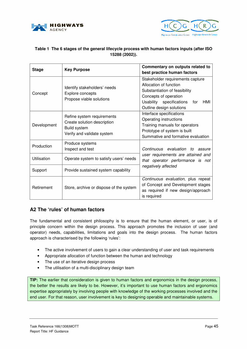
Task Reference 166(1308)MOTT Page 45
Report Title: HF Guidance
Table 1 The 6 stages of the general lifecycle process with human factors inputs (after ISO
15288 (2002)).
Stage Key Purpose Commentary on outputs related to
best practice human factors
Concept
Identify stakeholders’ needs
Explore concepts
Propose viable solutions
Stakeholder requirements capture
Allocation of function
Substantiation of feasibility
Concepts of operation
Usability specifications for HMI
Outline design solutions
Development
Refine system requirements
Create solution description
Build system
Verify and validate system
Interface specifications
Operating instructions
Training manuals for operators
Prototype of system is built
Summative and formative evaluation
Production Produce systems
Inspect and test
Utilisation Operate system to satisfy users’ needs
Support Provide sustained system capability
Continuous evaluation to assure
user requirements are attained and
that operator performance is not
negatively affected
Retirement Store, archive or dispose of the system
Continuous evaluation, plus repeat
of Concept and Development stages
as required if new design/approach
is required
A2 The ‘rules’ of human factors
The fundamental and consistent philosophy is to ensure that the human element, or user, is of
principle concern within the design process. This approach promotes the inclusion of user (and
operator) needs, capabilities, limitations and goals into the design process. The human factors
approach is characterised by the following ‘rules’:
• The active involvement of users to gain a clear understanding of user and task requirements
• Appropriate allocation of function between the human and technology
• The use of an iterative design process
• The utilisation of a multi-disciplinary design team
TIP: The earlier that consideration is given to human factors and ergonomics in the design process,
the better the results are likely to be. However, it’s important to use human factors and ergonomics
expertise appropriately by involving people with knowledge of the working processes involved and the
end user. For that reason, user involvement is key to designing operable and maintainable systems.

Task Reference 166(1308)MOTT Page 46
Report Title: HF Guidance
TIP: Poor design contributes to work-related ill-health and has been found to be a root cause of
accidents – well known examples include:.the Herald of Free Enterprise, Chernobyl and Ladbroke
Grove disasters.
It must be emphasised that the human factors approach has many wider benefits (in addition to those
documented in Section 1.2) including:
• Improved user engagement and uptake, central to project success
• Marketing and branding success
• Improved efficiency in development and implementation processes
• Reduced personnel costs (training and recruitment)

Task Reference 166(1308)MOTT Page 47
Report Title: HF Guidance
CASE STUDY: To date the launch of the 787 Dreamliner is the most successful commercial airplane
launch the world has ever witnessed. This example demonstrates the application of several
components of a human factors approach.
Since the launch, orders and commitments have been placed for more than 400 airplanes from five
continents. Firm orders are valued at $59 billion at current price lists. The creative alliance formed by
Teague and Boeing effectively demonstrates the benefits of fully collaborative, open-source design
processes.
Source: Dreamliner 2010
The design team comprised designers, engineers, sales and marketing, differentiation and
manufacturing representatives as well as partners and vendors. To ensure that all areas were
represented in tandem, the team held meetings over a period of five years. The team was bought
together to forge new ideas, to perfect existing concepts, to discuss findings and to engage in
discussions. The Dreamliner was inspired by the preceding design, the Sonic Cruiser which was
unveiled by Boeing in 2001.
The team were compelled to consider passengers and their needs, requirements of pilots, flight
attendants, mechanics, modifications engineers, leasing companies and almost anyone who would
come into regular contact with the new airplane. The researchers asked consumers to design their
vision of an ideal travel experience and enumerate elements of an aircraft interior that would best
allow that experience. Empirical and qualitative research performance at the Passenger Experience
Research Centre (PERC) offered a scale model of the airplane’s interior cabin to test and rapidly
iterate new ideas with the public in regard to passenger preference for cabin width, seat arrangement
and stowage, etc. The team developed concepts around individual travellers, anticipating what their
needs and wants would be. For the first time ever the unarticulated needs of the flying public were
embodied in the interior design. Source: All business 2010

Task Reference 166(1308)MOTT Page 48
Report Title: HF Guidance
A3 The design of control centres
The role of the operator in a control centre can be very demanding. The consequences resulting from
inappropriate operator action in control rooms, such as acts of omission, commission, timing,
sequencing and so on, can be potentially disastrous.
The design of a control centre is generally complex, involving multiple clients, conflicting objectives,
diversity of new technologies and possible solutions, ambitious schedules, first time applications and
inexperienced personnel.
TIP: For many project teams designing control rooms, human factors have been considered only
towards the end of the program, a delay that can cause problems that are not easy to resolve.
Therefore, the earlier you consider human factors, the greater the cost saving.
Similarly to other aspects of control room development, human factors need to be considered
systematically if unproductive work is to be avoided, and the initial approach needs to think about the
general requirements followed by specific, detailed needs.
ISO 11064 (Ergonomic Design of Control Centres) was developed specifically to describe the best
practice human factors process for the design of control centres and the detailed requirements
associated with specific elements of a control centre (e.g. layout/dimensions of workstations, displays
and controls, environmental requirements). Part 1 of ISO 11064 has been prepared to set up a
generic framework for applying requirements and recommendations relating to ergonomic and human
factors in designing and evaluating control centres with the view to eliminating or minimizing the
potential for human errors. Part 1 of ISO 11064 lists principles for the ergonomic design of control
centres, which are to be conducted across the different phases of the project lifecycle. This best
practice framework for design and development is summarised in Figure 6 and is the basis for the
Section 3 guidance.
In order to understand the characteristics of human performance for the purposes of interface design
there are many sources of information including: handbooks, best practice manuals, standards and
guidelines; and also a great many scientific theories, methods and models of human performance that
can be used to predict the effects of designs in terms of human performance variables. Therefore, it
is not possible to document all of these in this guidance document. However, relevant information
sources have been identified and key approaches and best practice summarised.

Task Reference 166(1308)MOTT Page 49
Report Title: HF Guidance
Figure 6 Ergonomic design process for control centres (after ISO 11064-1).
User characteristics and requirements
System features and requirements
1. Clarify goals and requirements
2. Define operator tasks
11. Gather operational feedback
POST-COMMISSIONING
DEVELOPMENT OF INITIAL DESIGN
6. Test initial design
DEVELOPMENT OF CONCEPT DESIGN
DEVELOPMENT OF DETAILED DESIGN
5. Define job and
work context
4. Define task requirements
3. Allocate function
7. Develop conceptual design
10. Test detailed design
9. Develop detailed design
8. Test conceptual design

Task Reference 166(1308)MOTT Page 50
Report Title: HF Guidance
Appendix B – How do I seek specialist Human Factors advice?
• Contact the Highways Agency HUMAN FACTORS CHAMPIONS via email:
o Provide a summary of your project and its intended outcome
o Provide a copy of the completed Human Factors Checklist to demonstrate the
specific areas where you may require support
• The human factors champions will be able to advise you on the Human Factors
Specialists that are available to support you via Highways Agency framework
agreements.

Task Reference 166(1308)MOTT Page 51
Report Title: HF Guidance
Appendix C – Justification for not seeking advice from a Human
Factors Specialist
If your responses to the questions in the flow chart on page 11 result in the recommendation that you
should seek advice from a human factors specialist and you do not follow this recommended course
of action, you need to provide a reason why and lodge this intention as per the instructions below:
• Review the checklist (on page 13-15) and review the relevant sections of the guidance as
suggested in the checklist;
• Complete the form below;
• Lodge a copy of the completed form with the project ICF, for audit purposes;
• Revisit this flow chart (and associated checklist) at each project stage boundary to reconsider
need for specialist human factors input and complete an additional form for the project file.
JUSTIFICATION FOR NOT SEEKING ADVICE FROM A HUMAN FACTORS SPECIALIST:
Your name
Your role on project
Name of project manager
(if different)
Name/ID of project
Stage boundary/gateway
Please justify why your
project does not require
expert input from a
Human Factors
Specialist
Your signature: Date:

Task Reference 166(1308)MOTT Page 52
Report Title: HF Guidance
Appendix D – Justification for seeking advice from a Human
Factors Specialist
If your responses in the flow chart on page 11 result in the recommendation that you should seek
advice from a human factors specialist and you follow this recommended course of action, you need
to lodge this confirmation as per the instructions below:
• Review the checklist (on page 13-15) and review the relevant sections of the guidance as
suggested in the checklist;
• Complete the form below;
• Lodge a copy of the completed form with the project ICF, for audit purposes;
• Revisit this flow chart (and associated checklist) at each project stage boundary to reconsider
need for specialist human factors input and complete an additional form for the project file.
JUSTIFCATION FOR SEEKING ADVICE FROM A HUMAN FACTORS SPECIALIST:
Your name
Your role on project
Name of project manager
(if different)
Name/ID of project
Stage boundary/gateway
Please comment on
why/which parts of your
project require expert
input from a Human
Factors Specialist
[insert step numbers of the guidance that were deemed to be relevant
based on your responses to the checklist questions]
Your signature: Date:

Task Reference 166(1308)MOTT Page 53
Report Title: HF Guidance
Appendix E – No requirement to seek advice from a Human
Factors Specialist/review Human Factors Guidance
If your responses to the questions in the flow chart on page 11 result in no requirement to seek advice
from a human factors specialist (and you follow this course of action), please lodge this intention as
per the instructions below:
• Review the checklist (on page 13-15) and review the relevant sections of the guidance as
suggested in the checklist;
• Complete the form below;
• Lodge a copy of the completed form with the project ICF, for audit purposes;
• Revisit this flow chart (and associated checklist) at each project stage boundary to reconsider
need for specialist human factors input and complete an additional form for the project file.
NO REQUIREMENT TO SEEK ADVICE FROM A HUMAN FACTORS SPECIALIST/REVIEW HUMAN
FACTORS GUIDANCE:
Your name
Your role on project
Name of project manager
(if different)
Name/ID of project
Stage boundary/gateway
Justification
The human factors checklist was completed on [INSERT DATE] and the
responses provided suggest that there is no requirement, at this stage,
to review the Human Factors Guidance or to seek specialist Human
Factors advice for the project.
Your signature: Date:

Task Reference 166(1308)MOTT Page 54
Report Title: HF Guidance
Appendix F – Justification for reviewing Human Factors Guidance
If your responses in the flow chart on page 11 result in the recommendation that you should review
the Human Factors Guidance and you follow this recommended course of action, you need to lodge
this confirmation as per the instructions below:
• Review the checklist (on page 13-15) and review the relevant sections of the guidance as
suggested in the checklist;
• Complete the form below;
• Lodge a copy of the completed form with the project ICF, for audit purposes;
• Revisit this flow chart (and associated checklist) at each project stage boundary to reconsider
need for specialist human factors input and complete an additional form for the project file.
JUSTIFCATION FOR REVIEWING THE HUMAN FACTORS GUIDANCE:
Your name
Your role on project
Name of project manager
(if different)
Name/ID of project
Stage boundary/gateway
Please comment on
why/which parts of the
Human Factors Guidance
were relevant to your
project at this stage
[insert step numbers of the guidance that were deemed to be relevant
based on your responses to the checklist questions]
Your signature: Date:

Task Reference 166(1308)MOTT Page 55
Report Title: HF Guidance
Appendix G – Justification for not reviewing the Human Factors
Guidance
If your responses in the flow chart on page 11 result in the recommendation that you should review
the Human Factors Guidance and you do not follow this recommended course of action, you need to
provide a reason why and lodge this intention as per the instructions below:
• Review the checklist (on page 13-15) and review the relevant sections of the guidance as
suggested in the checklist;
• Complete the form below;
• Lodge a copy of the completed form with the project ICF, for audit purposes;
• Revisit this flow chart (and associated checklist) at each project stage boundary to reconsider
need for specialist human factors input and complete an additional form for the project file.
JUSTIFICATION FOR NOT REVIEWING THE HUMAN FACTORS GUIDANCE:
Your name
Your role on project
Name of project manager
(if different)
Name/ID of project
Stage boundary/gateway
Please justify why you
do not need to review the
Human Factors Guidance
for your project
Your signature: Date:

Task Reference 166(1308)MOTT Page 56
Report Title: HF Guidance
Appendix H – Attributes of a ‘context of use description’
A context of use description needs to contain details about the following aspects of use, when known
(NB. This list is not exhaustive and may not be relevant to all situations):
Statement of operational goals
Purpose/objectives of system
Users Tasks Equipment
User types
- Primary
- Secondary and indirect users
Skills and knowledge
- Product skill/knowledge
- System skill/knowledge
- Task experience
- Organisational experience
- Level of training
- Qualifications
- Language skills
Personal attributes
- Age
- Gender
- Physical capabilities
- Physical limitations and disabilities
- Intellectual abilities
- Attitude
- Motivation
Task breakdown
Task name
Task frequency of use
Task duration
Frequency of events
Task flexibility
Physical and mental demands
Task dependencies
Task output
Risk resulting from error
Safety critical demands
Basic description
- Product identification
- Product description
- Main application areas
- Major functions
Specification
- Hardware
- Software
- Materials
- Services
Environment
Organisational environment Technical environment Physical environment
Structure
- Hours of work
- Group working
- Job function
- Work practices
- Assistance
- Interruptions
- Management structure
- Communications structure
Attitudes and culture
- Organisational aims
- Industrial relations
Job design
- Job flexibility
- Performance monitoring
- Performance feedback
- Pacing
- Autonomy
- Discretion
Configuration
- Hardware
- Software
- Reference materials
Workplace conditions
- Atmospheric conditions
- Auditory environment
- Thermal environment
- Visual environment
- Environmental instability
Workplace design
- Space and furniture
- User posture
- Location
Workplace safety
- Health hazards
- Protective clothing and equipment

Task Reference 166(1308)MOTT Page 57
Report Title: HF Guidance
Appendix I – Example of an Issues Log
The human factors Issues Log should be used to track all human factors issues/actions for the project. Each of the issues identified below, and those that
emerge as the design matures, should be addressed through appropriate and commensurate human factors activities and ergonomic input to the design
process. Below is an example Issues Log for the design of a new control room interface that enables operators to open the hard shoulder for use as a running
lane:
ID
Date /
step
identified
Date/
step last
updated
Issue
owner Issue Mitigation/ actions Status of action
Date/ step for issue
revisit
1 1 Jan
2010
Step 1
1 Feb
2010
Step 2
A. Person It is currently assumed that the
RCC operators will be
responsible for managing all
hard shoulder monitoring
activities. However the
number of staff required for
each task has not yet been
defined.
Task analysis needs to be undertaken to define the
tasks and so that the roles and responsibilities for the
different control room tasks need to be carefully
defined, substantiated through the task analysis and
user requirements and ultimately reflected in
procedures and training and the plant safety
management arrangements.
Ongoing issue 1 March 2010
Step 3
and
1 April 2010
Step 4
2 1 Jan
2010
Step 1
1 Jan
2010
Step 1
A. Person There needs to be a general
ergonomic consistency of all
user-interface, control and
display design and information
presentation.
Design in accordance with best practice standards
and appropriate task analysis output to ensure a
consistency across all user interfaces, controls and
displays is achieved throughout the control room to
minimise potential for operator errors to occur.
Ongoing issue 1 April 2010
Step 4
and
1 July 2010
Step 7
3 1 Jan
2010
Step 1
1 Jan
2010
Step 1
A. Person Displays should present cues
for operator actions as readily
interpretable signs and also
Design displays in accordance with best practice
standards and based on task analysis output to
ensure they are simple and easy to understand and
Ongoing issue 1 April 2010
Step 4

Task Reference 166(1308)MOTT Page 58
Report Title: HF Guidance
indicate any precondition for
their validity and feedback
success.
diagnose. and
1 July 2010
Step 7
4 1 Jan
2010
Step 1
1 Jan
2010
Step 1
A. Person Design of control room
workstations must ensure that
operation of a control does not
obscure any corresponding
display and visual field of the
operator over the controlled
equipment and that
simultaneous control activation
and viewing is possible without
awkward postures.
Design control stations and consoles in accordance
with human factors best practice to ensure adequate
viewing is provided over operations.
human factors review of technical specifications to
ensure adequate visual access to process.
Open issue 1 July 2010
Step 7
5 1 Jan
2010
Step 1
1 Jan
2010
Step 1
A. Person Software displays and controls
should enable operators to be
able to select and maintain
safety information, specific
alarms and critical parameters
without having to select
different windows or such
information being
obscured/marked or ‘flooded’
with other information.
Alarm/safety information
should always be on display to
ensure operator has
immediate access to safety
significant system information.
Human factors review of design technical
specifications.
Review of procedures to ensure the ability to select
and maintain safety information is adequately defined
and supported.
Design will follow requirements of project human
factors style guide and ISO standards.
Task analysis to inform specific requirements and any
trade offs for control room operations.
Ongoing issue 1 April 2010
Step 4
and
1 July 2010
Step 7

Task Reference 166(1308)MOTT Page 59
Report Title: HF Guidance
Appendix J – Where to find further Human Factors information: standards and associated areas of
application
Reference Year
Standard
or
Guidance
Work
pla
ce
Work
space
Enviro
nm
ent
Dis
pla
ys
Contro
ls
Input D
evic
es
Com
mun
icatio
n
Ala
rms
HM
I
Labe
lling
Colo
ur
Genera
l hu
man
facto
rs
BS EN 614 – Safety of Machinery -
Ergonomic Design Principles
Part 1 – Terminology and General
Principles
1995 Standard � � � � � � �
BS EN 614 – Safety of Machinery –
Ergonomic Design Principles
Part 2: Interactions between the
design of machinery and work tasks
2000 Standard �
BS EN 981 – Safety of Machinery –
System of auditory and visual danger
and information signals
1997 Standard � � �
BS 7517 – Nuclear Power Plants –
Control Rooms – Operator Controls 1995 Standard � � � � � � �
EN ISO 11064 - Ergonomic design of
control centres – Part 1: Principles for
the design of control centres
2001 Standard �
EN ISO 11064 - Ergonomic design of
control centres – Part 2: Principles for
the arrangement of control suites
2001 Standard � � � � �

Task Reference 166(1308)MOTT Page 60
Report Title: HF Guidance
Reference Year
Standard
or
Guidance
Work
pla
ce
Work
space
Enviro
nm
ent
Dis
pla
ys
Contro
ls
Input D
evic
es
Com
mun
icatio
n
Ala
rms
HM
I
Labe
lling
Colo
ur
Genera
l hu
man
facto
rs
EN ISO 11064 – Ergonomic design of
control centres – Part 3: Control room
layout
2000 Standard � � � � �
EN ISO 11064 – Ergonomic design of
control centres – Part 4: Layout and
dimensions of workstations
2004 Standard � � �
EN ISO 11064 – Ergonomic design of
control centres – Part 5: Displays and
controls
2008 Standard � �
EN ISO 11064 – Ergonomic design of
control centres – Part 6:
Environmental requirements for
control centres
2005 Standard �
EN ISO 11064 – Ergonomic design of
control centres – Part 7: Principles for
the evaluation of control centres
2006 Standard � � � � � � � � � � � �
BS EN 894 – Safety of machinery –
Ergonomics requirements for the
design of displays and control
actuators – Part 1: General principles
for human interactions with displays
and control actuators
1997 Standard �
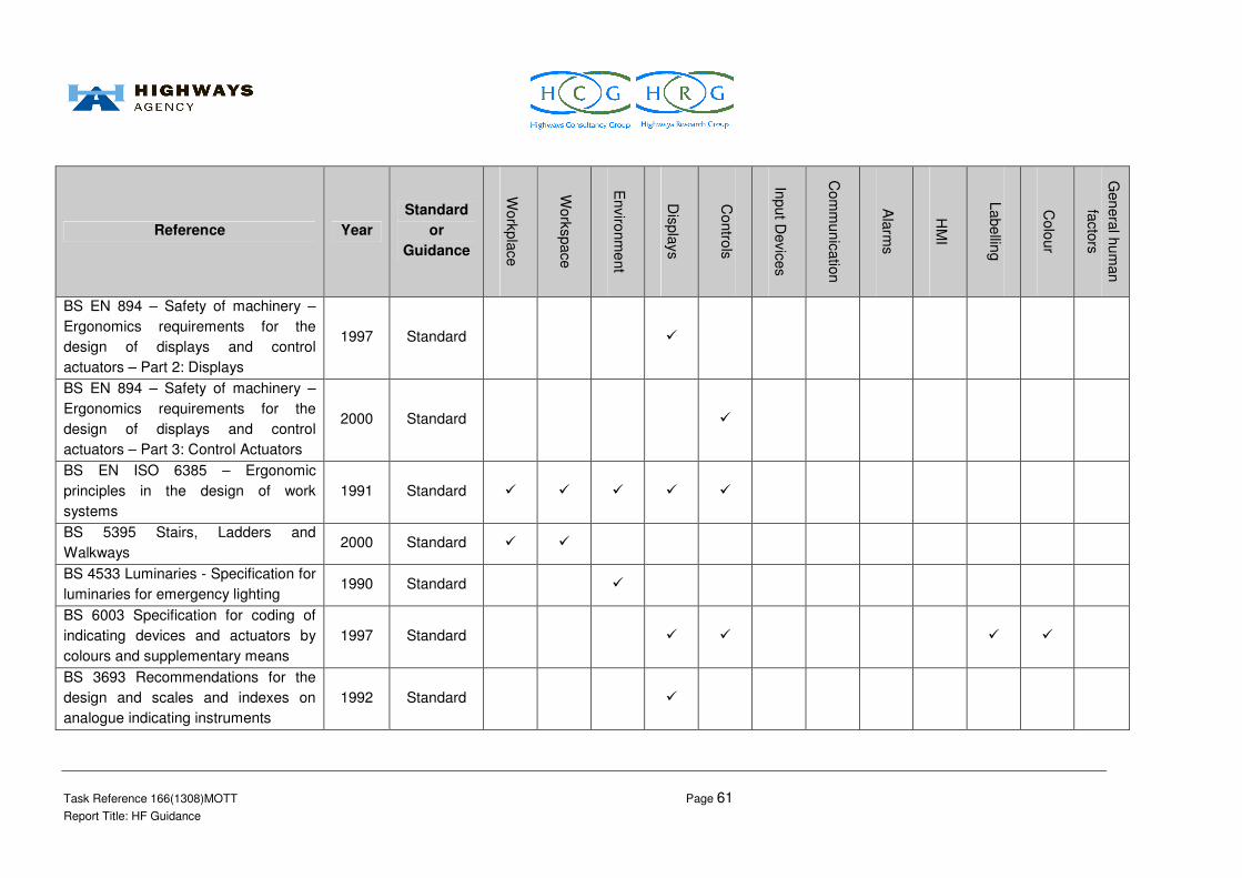
Task Reference 166(1308)MOTT Page 61
Report Title: HF Guidance
Reference Year
Standard
or
Guidance
Work
pla
ce
Work
space
Enviro
nm
ent
Dis
pla
ys
Contro
ls
Input D
evic
es
Com
mun
icatio
n
Ala
rms
HM
I
Labe
lling
Colo
ur
Genera
l hu
man
facto
rs
BS EN 894 – Safety of machinery –
Ergonomics requirements for the
design of displays and control
actuators – Part 2: Displays
1997 Standard �
BS EN 894 – Safety of machinery –
Ergonomics requirements for the
design of displays and control
actuators – Part 3: Control Actuators
2000 Standard �
BS EN ISO 6385 – Ergonomic
principles in the design of work
systems
1991 Standard � � � � �
BS 5395 Stairs, Ladders and
Walkways 2000 Standard � �
BS 4533 Luminaries - Specification for
luminaries for emergency lighting 1990 Standard �
BS 6003 Specification for coding of
indicating devices and actuators by
colours and supplementary means
1997 Standard � � � �
BS 3693 Recommendations for the
design and scales and indexes on
analogue indicating instruments
1992 Standard �

Task Reference 166(1308)MOTT Page 62
Report Title: HF Guidance
Reference Year
Standard
or
Guidance
Work
pla
ce
Work
space
Enviro
nm
ent
Dis
pla
ys
Contro
ls
Input D
evic
es
Com
mun
icatio
n
Ala
rms
HM
I
Labe
lling
Colo
ur
Genera
l hu
man
facto
rs
BS 10075 Ergonomic principles
related to mental workload 2000 Standard � �
BS 9921 Ergonomic assessment of
speech communication 1996 Standard �
BS 60447 Man-Machine Interface
Actuating principles 1994 Standard � � �
BS 7179 Ergonomics of design and
use of visual display terminals in
offices
1990 Standard �
BS EN ISO 8995 Pt 1 Lighting of
indoor work places 2002 Standard �
BS 13407 Human-centred design
processed for interactive systems 1999 Standard �
ISO 11428 Ergonomics Visual Danger
signals 1996 Standard � � �
ISO 11429 Ergonomics System of
auditory and visual danger and
information signals
1996 Standard � � � �
NUREG-0700, Revision 2, - Human-
System Interface Guidelines
U.S. Nuclear Regulatory Commission
2002 Guidelines � � � � � � � � � � � �

Task Reference 166(1308)MOTT Page 63
Report Title: HF Guidance
Reference Year
Standard
or
Guidance
Work
pla
ce
Work
space
Enviro
nm
ent
Dis
pla
ys
Contro
ls
Input D
evic
es
Com
mun
icatio
n
Ala
rms
HM
I
Labe
lling
Colo
ur
Genera
l hu
man
facto
rs
Human Factors in the Design and
Evaluation of Air Traffic Control
Systems (Cardosi and Murphy)
1996 Guidelines � � � � � � � � � � � �
DEF STAN 00-250 Part 0 (2008) –
Human Factors Integration 2008 Guidelines �
DEF STAN 00-250 Part 1 (2008) –
Overarching People-Related
Requirements
2008 Guidelines �
DEF STAN 00-250 Part 2 (2008) –
Particular People-Related
Requirements
2008 Guidelines �
DEF STAN 00-250 Part 3 (2008) –
Technical Guidance 2008 Guidelines � � � � � � � � � � � �
DEF STAN 00-250 Part 4 (2008) –
Human Factors Integration Methods,
Tools and Techniques
2008 Guidelines � � � � � � � � � � � �
Human Factors in Engineering and
Design (Sanders and McCormick) 1992 Guidelines � � � � � � � � � � � �
The Ergonomics of Workspaces and
Machines (Corlett and Clark) 1995 Guidelines � � � � � � � � � � � �

Task Reference 166(1308)MOTT Page 64
Report Title: HF Guidance
Reference Year
Standard
or
Guidance
Work
pla
ce
Work
space
Enviro
nm
ent
Dis
pla
ys
Contro
ls
Input D
evic
es
Com
mun
icatio
n
Ala
rms
HM
I
Labe
lling
Colo
ur
Genera
l hu
man
facto
rs
People in Control – Human Factors in
Control Room Design (Noyes and
Bransby)
2001 Guidelines � �
Bodyspace – Anthropometry,
Ergonomics and the Design of Work
(Pheasant)
1986 Guidelines � � � � � �
Ergonomics at Work – Human Factors
in Design and Development (Oborne) 1995 Guidelines � � � � � � � � � �
Human Factors in Alarm Design
(Stanton) 1994 Guidelines �
Human Factors in Auditory Warnings
(Stanton and Edworthy) 1999 Guidelines �
HS(G)48 Reducing Error and
Influencing Behaviour (HSE) 1999 Guidance �

Task Reference 166(1308)MOTT Page 65
Report Title: HF Guidance
Appendix K – Guidance on the design of displays and controls
HMI Design Guidelines (Controls)
• The HMI should be designed to be ‘error tolerant’. Single errors made by operators (e.g.
operation of wrong control/push-button, the misreading of a display and subsequent action
following this) should, as far as possible, not lead to a major error consequence
• Feedback should be provided when a control has been successfully actuated (audible, tactile,
visual) with minimal perceivable delay unless a time delay is avoidable where intermittent
feedback should be provided
• The process of designing the layout of HMI workstations and control panels should involve
the definition of control actions required, information requirements, control and instrument
types, and arrangements of these on the available panel surfaces, applying labels,
demarcations and coding techniques to support operator task performance. This information,
at least in part, is best delineated from task analysis
HMI control panel layout
Panel layout design relies heavily upon information generated from task analysis as this will affect
how panels are structured in terms of display/control relationships, information presentation and
feedback, grouping etc.
• The basic criteria that need to be considered when situating controls and displays are:
o Duration
o Importance
o Frequency
o Visibility and feedback
o Clear associations between a control action and corresponding equipment and/or
display response
o Response time
• HMI/control panels should be located for easy access within the workspace. Panels should
be easily accessible but of out main circulation routes to reduce the possibility of inadvertent
operation of controls
• The design and position of panels should support maintenance as well as normal operation
and allow sufficient space around HMI/control panels for maintenance activities
Control devices
• Task analysis should be used to inform the selection of control devices, the decision should
be made balancing the following:
o Function of control
o Requirements of the control task – safety significant, coarse, fine control, precision
required
o Information required to guide the operator
o Requirements imposed by the workspace
o Consequences of error

Task Reference 166(1308)MOTT Page 66
Report Title: HF Guidance
Once this information has been obtained, the following guidelines should be applied:
Control Arrangements and Grouping
• Control devices should be designed so that they can be operated by the 5th through to 95
th
percentile of the target population in comfort, without requiring adoption of forced postures
• Control heights should be suitable (940mm -1500mm for general use; 940mm - 1270mm for
precise/frequent use)
• There should be sufficient space in front of equipment for crouching, for any controls that are
required to be located below this height
• Controls should take into account clothing limitations and operating environments
• Controls should be designed so that they do not place unacceptable demands on operators in
terms of speed and accuracy of operation and forces required to operate them. They should
be able to be operated with the least possible movement relative to function and operating
resistance
• Most controls can be operated equally well with both hands. However, controls that demand
accurate, and/or fast, operation should either be capable of being operated by either hand
• Consider the position of the operator – seated, standing; squatting needed to operate control
devices, consider need for adjustability of controls. For accurate operation, prefer seated.
The body movements required to operate controls (or displays) should not cause discomfort
• Foot pedals should be considered only if no other means for control is applicable
• Controls essential for system safety and critical tasks should be centrally mounted within easy
reach
• Controls that attain high assessment scores for frequency, duration and importance should be
centrally mounted
• Emergency stops shall be clearly visible and identifiable
• Emergency stops should be consistent in location, easily accessed/reached, and located in
front of the operators' normal positions to ensure easy and non-hazardous operation
• The emergency stop function shall be available at all times
• When the emergency stop function is actuated, the system shall remain in that state until it is
reset manually
• The space between controls (and displays) needs to be optimal in order to ensure efficient
operation. Too much space may demand unnecessary movements, while too little space may
cause accidental operation. Individual controls should be adequately separated to prevent
confusion/inadvertent initiation, and be easily and accurately operated (13mm edge to edge,
increased if gloves are worn). This distance may need to be increased or use other means of
ensuring the correct control/pushbutton is identified before it is operated if the inadvertent
operation would have a significant consequence. The operator may fail to notice the error in
selecting a control, particularly if he/she is hurrying or stressed by an abnormal situation
Other means of preventing inadvertent operation are as follows:
• Control/push-button operation may be interlocked by software to disable it and thus prevent
operation at the wrong time (beware implications of software reliability claims and its use in
safety-related systems)

Task Reference 166(1308)MOTT Page 67
Report Title: HF Guidance
• Push-buttons can be recessed or have a covering flap (when the flap is in the open position it
should interfere with other controls or displays). Ideally, the cover should return to its start
position if not manually held open
• Use of another type of control may be necessary if it proves to be very important to prevent
operation at the wrong time e.g. ‘pull and twist’ action; or the push-button/control may need to
be physically locked (key-switch) or ‘dead-mans handle’ design
Control Devices – Direction of Movement
• How a human-machine operates and its controls should utilise the natural relationships of
control movement habit patterns, which are consistent from person to person without special
training
• As far as possible, the necessary action of a control should be correlated to the required final
effect, according to the operating direction (movement) of a control, user expectations or to
the relative location of controls
• Under stress operators can be expected to revert to population stereotypes even of they have
been trained to act in a different way
• The function, movement and position of controls and display elements should correspond to
what the operator expects
Control and Display Association
• Layout of HMI/control panels should support human performance to reduce confusion
between different controls/displays. Devices can be grouped by importance, frequency of
function, or sequence of use
• Associated sets of controls should be arranged according to their priority e.g. highest priority
– top/left; lowest priority – bottom/right. The grouping principles shall be consistent across the
facility and with the user’s mental model of the system established by task analysis and
training. The association between controls and displays is important and the general
guidelines that should be followed are:
o Locate all controls and push-buttons for easy access by operators
o Controls that are functionally related should be grouped together unless task analysis
indicates that a more task-oriented grouping would better reflect and support control
usage
o Control devices shall be logically grouped according to their operational of functional
correlation, for controlling a process, machine or equipment. Grouping principles
shall be consistently applied throughout the facility. The arrangement and grouping
of controls should be structured to minimise the probability of incorrect actuation
arising from human errors
o Where controls are grouped, ensure good separation between individual
controls/push-buttons and good labelling/coding, to prevent inadvertent operation.
Functionally related controls and displays should be grouped together, with groups
separated by minimum 50mm
o Sequentially used controls/displays should be positioned in order/sequence (use the
following sequence – left to right, or top to bottom (consider the nature of the use, e.g.
if they are only used for maintenance, lay out appropriately for this and not normal
operations). This reduces errors and increase speed of performance

Task Reference 166(1308)MOTT Page 68
Report Title: HF Guidance
o All controls having sequential relations, or associated with a particular function or
operation, or which are operated together, should be grouped together along with
their associated displays/indications
o If a control is adjacent to the instrument it controls or other displays, it should be
located so that the operator’s control hand/arm normally used for setting does not
obscure the indicator or other displayed information
o Warning lights should be integral with levers, switches or other control devices by
which the operator is to take action
o It should be ensured that there is clear line of sight between a control and
corresponding display which is intended to provide indication of the correct control
action (if actual direct visual access over the task/equipment being controlled is not
possible)
o Place controls and their associated displays so that they are near each other and it is
clear which relate to each other
o The operation of a control should produce a corresponding display response, which
should be consistent, predictable and compatible with operator expectations and the
direction of associated system responses. Ensure that the results of control actions
are as the operator expects e.g. the operator would expect an alarm light to
extinguish following reset operation
o Verification that an operator action has been accepted by the system should be
presented to the operator without unnecessary delay. If execution is prolonged, the
operator should be informed of this or preliminary feedback provided
o The feedback provides to the operator should confirm that the control action has
achieved its desired system/equipment response/end state and not simply that it has
been demanded
HMI Design Guidelines (Displays and Alarms)
• A display is a device that presents information to the operator. Examples of HMI displays
include: indicators, enunciators, gauges, digital counters, computer monitors, video display
units, CCTV, etc.
• Display devices may have single or multiple display functions. A single function device
presents information in a fixed format e.g. an indicator that presents a single variable and a
VDU that presents a single page containing a set of variables. A multiple-function device
contains a set of display pages through which the user navigates to access desired
information
Displaying HMI information
• The organisation (e.g. grouping) of displayed information is important for supporting prompt
recognition and comprehension of plant status to operators. Related information may be
organised by the physical arrangement of single and multiple-function display devices. For
example, functionally related individual display devices may be grouped together in the same
portion of a console or panel. Within a multiple-function device, the information is also
organised by its placement within a display page and by the arrangement of display pages

Task Reference 166(1308)MOTT Page 69
Report Title: HF Guidance
Design to support task requirements
• Positioning of displays should consider the context of use:
o Importance of displayed information, in terms of safety, overall objective and relative
to other displays
o The sequence in which information may be required during normal and
fault/emergency conditions
o Frequency with which information should and can be viewed
o The information provided should be appropriate and sufficient to perform the task and
make unambiguous diagnosis
Display Screen Visual Access
• The minimum viewing distance for displays should be 500mm. The maximum viewing
distance should be appropriate for the size, contrast, lighting, and task precision required.
Precise requirements should be obtained from task analysis
• Surfaces/screens should be free from disabling and discomfort glare or reflections that may
reduce luminance contrast and interfere with the task
• Display heights should be 940mm - 1800mm for general use, 1150mm-1530mm for
precise/frequent use
Display Information Presentation Requirements
• Displays are rarely used in isolation and therefore the design of appropriate layouts for groups
of displays can be as important as the design of each separate display. There may be
grounds for integrating more than one display or even integrating information from several
displays
• Displays and information they present should be arranged so that they are easy to use in
combination by grouping items:
o Where displays (or corresponding controls) are used in a fixed sequence, they should
be arranged in that sequence. This arrangement helps the operator to remember the
sequence and it decreases the response time and leads to fewer errors
o Where displays (and control) are not operated in a fixed sequence the following
arrangements for grouping should be applied:
� Displays (and controls) used for safety functions and emergencies should be
designed and positioned so that they can be used quickly, easily and
accurately. The safety important and frequently used items should be
located/displayed in the most accessible positions
� Items in sub-sequences are placed together
� Functionally related items are placed in groups with visual and spatial
separation from other items
� Displays for monitoring safety parameters should continuously display this
information
� Information should be presented on a single display or display page unless
this is very cluttered, (if trade off is required err towards completeness of
information)
• Special consideration needs to be given to the type and amount of information presented to
and processed by the operator:

Task Reference 166(1308)MOTT Page 70
Report Title: HF Guidance
o Information should be presented so that it consistent across all interfaces and can be
recognised (rather than trusting to recall)
o Information presentation should be offered to reduce complexity
• In check reading, the accuracy of such readings may be enhanced if the pointers of the
displays are arranged into a pattern so that it is easy to determine if one or several pointers
deviate from the normal patterns
• Safety significant parameters that may be indicated by small changes in display status should
be avoided as these place excessive vigilance requirements on operators
• Safety function displays should allow operators to comprehend a change in safety status in a
matter of seconds
• The sampling rate for displayed safety functional information should be consistent with the
operator’s needs for performing tasks. There should be no meaningful loss of information in
the presented data
• Information and data should be displayed in a consistent and concise format and this should
be segregated from other information
• The display’s response to fault conditions and transients should keep the operator informed of
current plant status
• Where appropriate, magnitudes and trends in safety related variables should be displayed to
aid diagnosis. Sufficient resolution in time and magnitude should be provided to ensure that
rapidly changing variables can be observed and accurately interpreted
• Displayed information should be reliable and failure indications should be used to inform the
user of the presence of failures or malfunctions
• Narrow spatial location between displays or integral displays may help parallel processing
(performance of several operations simultaneously). If a system requires parallel processing,
the designer should consider the use of displays made for different senses
• Displays should be placed within the operator’s field of vision (ideally +/- 30 ° of horizontal line
of sight)
• Important information in terms of safety and frequently consulted information should be
located in the central areas most frequently scanned by the eye and presented in a clear,
convenient and accessible way
• Information should be presented in the necessary form and so that it does not require further
transposing, calculation or analysis
VDU/Computer Screens
• VDU displays should be designed such that they are adjustable in position, contrast,
brightness, with no perceivable flicker and good colour combinations
• Flashing alerts should be synchronous and at a single rate, 2-3Hz, and reserved for important
information
• The overall screen (menu) structure should be hierarchical where possible, and broad rather
than deep (maximum 5 levels), with a simple means to move up, down and across
• Each display should contain complete information for an operator decision
• Each screen should have a unique and informative title to aid user navigation
• Screen formats should be consistent, with irrelevant detail avoided
• Where relevant, process overview displays should be provided to operators to avoid
attentional capture and to maintain situational awareness

Task Reference 166(1308)MOTT Page 71
Report Title: HF Guidance
• Important information and alarm information should not be lost when navigating between
screen levels
CCTV
• Viewers should be able to adjust the image (focus, brightness, contrast, screen position and
angle) to present adequate detail for the task (the image should be stable and upright)
• Positioning of CCTVs should be examined to ensure all required information is obtainable
• An adequate view of the task should be presented
• Access for regular cleaning and maintenance is required to maintain image quality
• If simultaneous views are required, sufficient monitors or split screen viewing should be
provided
• Each view should be adequately labelled or distinguished (to avoid confusion)
Status indicators/Indicator lamps
• Position valves and other equipment status indicators such that operators can see status of
valve/equipment from all operating positions relevant to the task and irrespective of current
lighting conditions
• Ensure stray lighting in the workplace does not make any local or control panel indicator
appear illuminated when it is not. Similarly, ensure that the illuminated indicator is sufficiently
bright to ensure that it is clear when on
• Use standard colours. Avoid red or yellow as these are typically ‘alarm’ colours. White is
good as a status indicator (refer to section of Coding and Labelling)
• Ensure operators understand the meaning of status indication. If indicator lights are used to
indicate that a particular control action has been carried out ensure that they positively
indicate the final status of the equipment e.g. equipment end state linked to indicator not the
request of demand
Alarms/Warnings
• Alarms and warnings are status indicators designed to attract attention to a condition
requiring timely and urgent operator intervention. They should assist the operator in
diagnosing the problem through conveyance a special message to an operator that requires
some action or indicates an immediate event. Most alarms must serve two purposes:
o To direct attention to the message that indicates a condition/fault/deviation has
occurred
o Convey the meaning of the message
• Alarms systems should be developed in accordance with a defined philosophy for
prioritisation of alarms, their processing and presentation, control and management
• Consistency of alarm and interface design must be maintained throughout the plant, this
includes any alarms that may exist as part of any Commercial-of-the-Shelf items, as different
manufacturers tend to have their own agendas and philosophies for alarms which may be
wholly inconsistent with the overall project’s design conventions. This could lead to confusing
signals to operators and sensory overload, increasing the likelihood of misdiagnosis and
incorrect response to alarms

Task Reference 166(1308)MOTT Page 72
Report Title: HF Guidance
• The design and alarm philosophy should consider the overall demands on operators and
ideally be based on task analysis
Communication Systems
• Adequate communication facilities should be provided at all major operating locations
• There should be an adequate number of communication facilities provided around the control
suite, particularly for emergency response and control
• The communication systems should consider requirements for emergencies, not just normal
operations
• Appropriate communication devices and requirements should be selected and used having
regard to the tasks, physical and cognitive demands, prevailing hazards and environment e.g.
clarity of sound/usability of headsets/radios
Software
• Software design should be appropriate for the task and enable users to complete the task
efficiently without presenting unnecessary problems or obstacles
• Operators should be able to feel that they can master the system and use it effectively
following appropriate training
• Dialogue between the user and software should be appropriate for the user’s ability
• The software should protect users from the consequences of error, for example by providing
appropriate warnings and information and by enabling ‘lost’ data to be recovered
• The software system should provide appropriate feedback, which may include error
messages, suitable assistance to users and messages about changes in the system status,
malfunctions etc.
• Speed of response to commands and instructions should be appropriate to the task and the
user’s abilities
• Characters, cursor movements and position changes should be shown on screen as soon as
they are input
• Operators should be kept informed about the introduction, operation, functions and limitations
of software/software based systems
HMI Design Guidelines (Coding and Labelling)
• Coding can help operators to identify the correct controls, displays and alarms
• Coding and labelling of control devices (and displays) increases operating reliability, reduces
operating time and accelerates training and learning by improved visual and /or tactile
differentiation
• All control actuators, displays and alarms should be readily identifiable
• Coding can generally take the following forms:
o Visual/Colour
o Labels/Text
o Size/Shape
o Position
o Auditory

Task Reference 166(1308)MOTT Page 73
Report Title: HF Guidance
• The selection of the appropriate coding technique requires the designer to take into account
the safety significance and demands imposed by the nature and conditions of the operator’s
task. For example, colour coding and label coding will not be useful if the operator must
constantly maintain attention to a visual display or piece of work while selecting a control
Control device coding and labelling guidelines
As a guide, designers should consider the following factors before selecting a coding method:
• Space available for certain coding techniques (e.g. labels)
• Maintaining a balance between coding techniques and other human factors aspects. For
example, the ideal coding solution may entail a series of large colour coded dials or push
buttons, however, the sizes required conflict with optimum viewing angle of the operator
• Illumination of the workplace will affect the usefulness of some visual codes
• Speed and accuracy with which controls must be identified, touch is slower and usually less
accurate than vision
• Number of controls to be coded; labels are infinitely variable, three or four colours only should
be used throughout the facility
• Standardisation of coding of control devices, displays and alarms within the workplace is
essential to ensure consistency of interface design and that operators do not confuse coding
and control actions around the facility
• Colour used to associate meaning should be unambiguous, not contradictory and applied
consistently across the control room interfaces and not be the sole means of coding.
Generally, colour coding should be used as a ‘redundant’ code e.g. use stripes as well to
account for colour-blindness and different lighting conditions. Shape coding is also possible
e.g. rectangular vs. circular push-buttons
• Controls and push-buttons can also be coded by size
• Colour code controls/push-buttons for one function different to those associated with other
functions
• Whichever coding convention is to be adopted, it must be ensured that it is consistent with
user expectations and stereotypes and the meaning of coding is translated in procedures and
training. If unsure of the coding to be used, suitable prototyping and trials can be performed
to ensure controls are readily distinguishable under the expected conditions of use
Labelling
• All equipment, controls and displays should be clearly, legibly and consistently labelled, so
that they can be viewed from the operating position
• Use negative contrast for text on labels (e.g. dark letters on light/white background)
• Characters should be upright, uppercase (unless several lines of text are used where mixed
cases is more legible and recognisable); text wording, size, colour and typeface effect
readability
• Physical construction of labels effects long term durability/wear. Labels should therefore be
durable and permanent (adhesive labels are only acceptable for small components)
• Correct positioning of labels in relation to the control/push-button/displays/alarms will aid
identification

Task Reference 166(1308)MOTT Page 74
Report Title: HF Guidance
o Labels should be nearer to the corresponding pieces of equipment, display or control
than any other
o Labels, signs and informative text or symbols should be located on or adjacent to
their associated controls and displays in such a position that they are visible when the
controls are operated
• Labels should be consistently positioned
• Any nomenclature, symbols and abbreviations used in the labels should be standard,
conventional and compatible across the plant (punctuation should not be included) and
accurately repeated in operating procedures
• Names on equipment labels should be consistent with names used in procedures


![Human Factors and Usability Engineering – Guidance on the … · 2021. 2. 11. · guidance on human factors related to medical devices [2]; the MHRA guidance is intended to be consistent](https://static.fdocuments.us/doc/165x107/60f04ecfca9f8a0c3b1becb3/human-factors-and-usability-engineering-a-guidance-on-the-2021-2-11-guidance.jpg)

