Best Practice Cable · PDF fileSubsea Cables •Installation of cables in the marine...
35
Best Practice Cable Installation March 2012
Transcript of Best Practice Cable · PDF fileSubsea Cables •Installation of cables in the marine...

Best Practice Cable Installation
March 2012
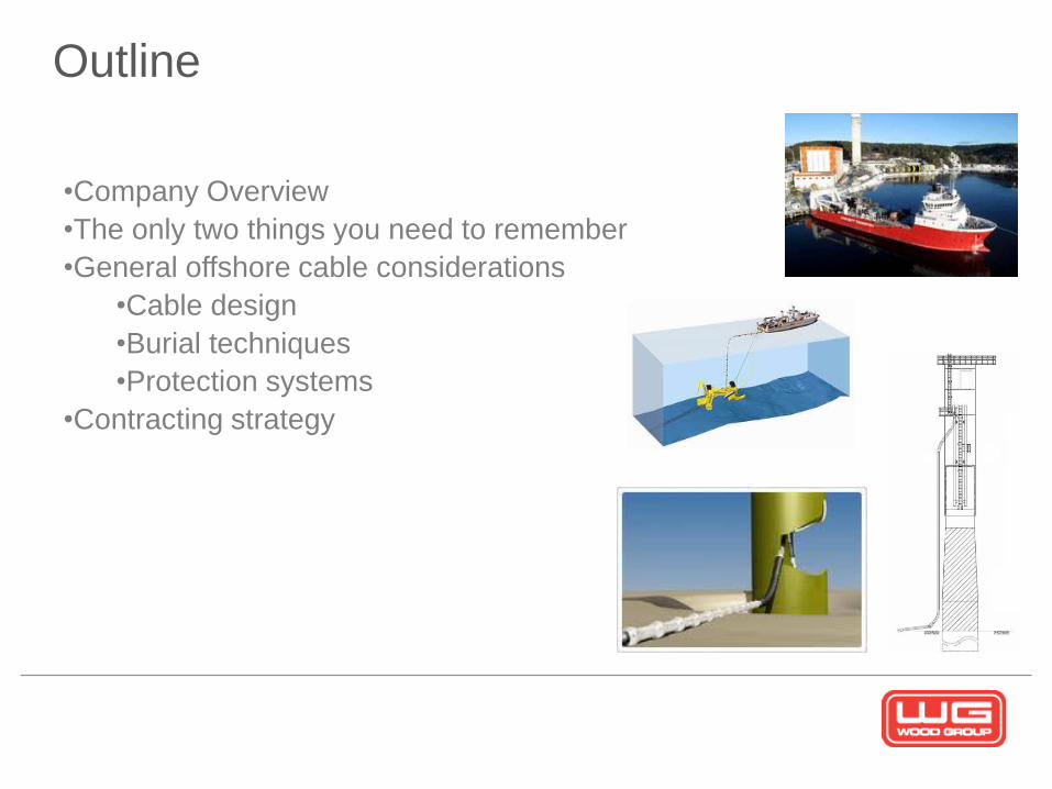
Outline
•Company Overview
•The only two things you need to remember
•General offshore cable considerations
•Cable design
•Burial techniques
•Protection systems
•Contracting strategy

Introduction to the Group
38,000
employees
Operations in
50 countries $6.1bn sales
John Wood Group PLC Servicing Energy Industries Worldwide
A Global Market Leader in:
• Engineering and Project Management for
Oil and Gas and Renewable Energy
Developments
• Field Operation and Maintenance
• Industrial Turbines

Wood Group Renewables
Engineering – Market Leading Positions
• 40 years of unrivalled offshore expertise
• We have worked on
– 75% of GOM deepwater facilities
– 30% of deepwater facilities worldwide
• We have engineered the WORLD’S DEEPEST
– TLP - Magnolia 4,744’
– SPAR – Perdido 7,800’
– Production platform – Independence Hub
Semi 7,920’
• LARGEST independent SUBSEA technology
group of its kind in the world
• Engineered more than 500,000km of cables &
pipelines
• Engineered, managed or appraised OVER
HALF of all subsea development worldwide
• We have DESIGNED and PROJECT MANAGED
subsea developments in water depths up to
3,000 METRES
• Experienced working in HIGH ENERGY areas –
large waves, currents, cyclones, etc
Structures & topsides Subsea solutions
• Involvement in access of 800 RENEWABLE
ENERGY projects to date
• Assessed OVER 60,000 MW of renewable
energy development internationally

Health, Safety & Environment
“Maintaining the highest standards in safety across
all of our operations worldwide at all times is of paramount importance”
As expressed in our Vision for HSE Excellence,
as an integral part of our business we will
Maintain a healthy workplace
Prevent accidents
Minimise adverse environmental impact
* Total Recordable Case Frequency per million man hours
7.1 5.8
4.6 4.2 3.9 3.33 3.26 2.94 2.49
2003 2004 2005 2006 2007 2008 2009 2010 2011Oct
Safety Cases*
5
Wood Group Renewables
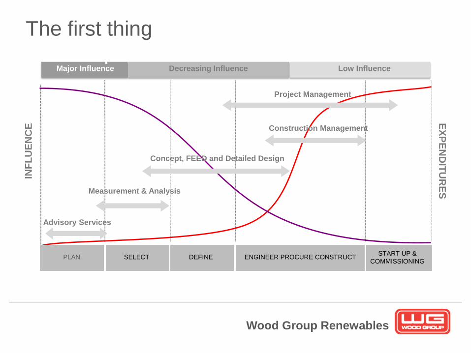
Project Lifecycle – Influence on Expenditure
& Concepts
Advisory Services
INF
LU
EN
CE
EX
PE
ND
ITU
RE
S
Major Influence Decreasing Influence
Project Management
Measurement & Analysis
Construction Management
Concept, FEED and Detailed Design
Low Influence
ENGINEER PROCURE CONSTRUCT START UP &
COMMISSIONING PLAN SELECT DEFINE
The first thing
Wood Group Renewables
Project Lifecycle – Influence on Expenditure
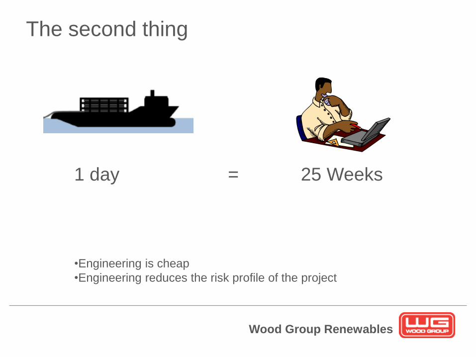
& Concepts The second thing
1 day = 25 Weeks
•Engineering is cheap
•Engineering reduces the risk profile of the project
Wood Group Renewables
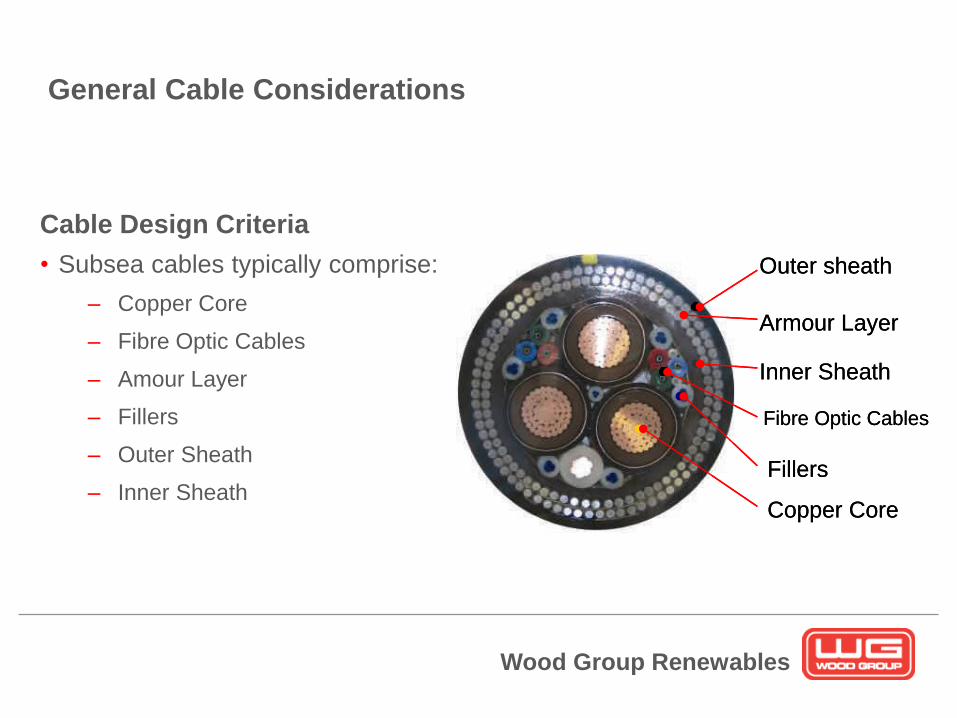
Subsea Cables
Cable Design Criteria
• Subsea cables typically comprise:
– Copper Core
– Fibre Optic Cables
– Amour Layer
– Fillers
– Outer Sheath
– Inner Sheath
Outer sheath
Armour Layer
Inner Sheath
Fillers
Copper Core
Fibre Optic Cables
Outer sheath
Armour Layer
Inner Sheath
Fillers
Copper Core
Fibre Optic Cables
General Cable Considerations

Wood Group Renewables
Subsea Cables
Cable Design Criteria
• For all subsea cables, the following aspects are considered during the
design process:
– Power requirements
– Resistance to anticipated in-service loads
• Free spanning
• Vortex Induced Vibration (VIV)
• On-bottom stability
• Hydrostatic pressure
• Exposure to trawl gear
– Resistance to anticipated transportation and installations loads
• Dynamic loads and curvature during installation
• Establish need for secondary protection
Wood Group Renewables
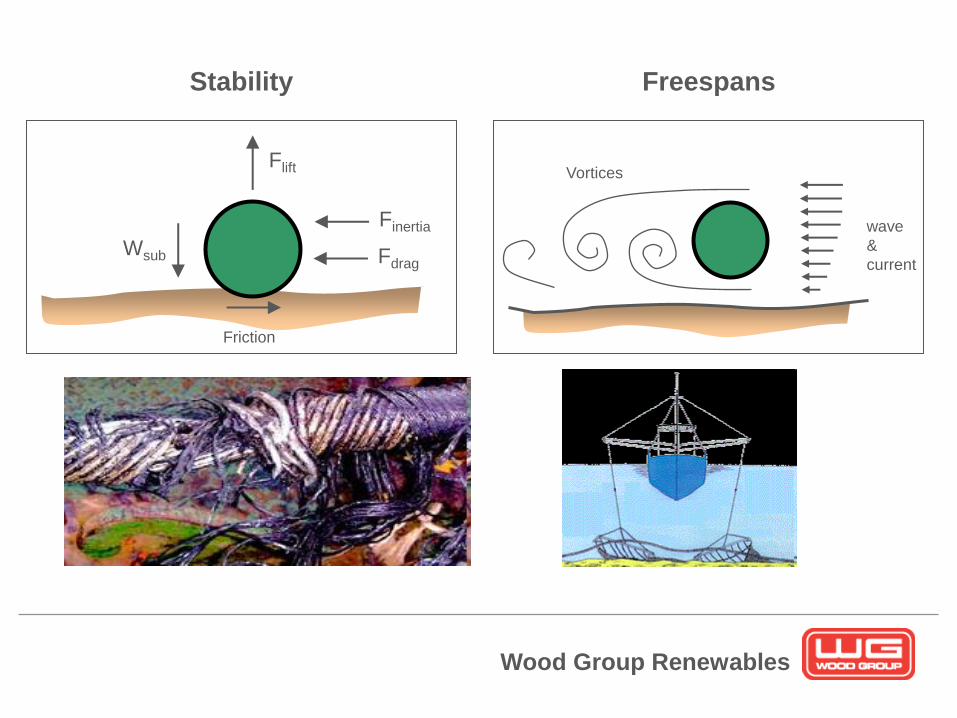
Reasons for Rock Dumping
Finertia
Fdrag
Flift
Wsub
Friction
Stability
wave
&
current
Vortices
Freespans
Wood Group Renewables
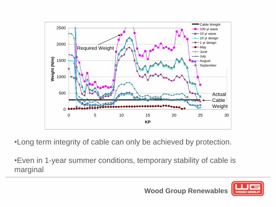
Cable Stability
0
500
1000
1500
2000
2500
0 5 10 15 20 25 30
KP
We
igh
t (N
/m)
Cable Weight
100 yr wave
10 yr wave
10 yr design
1 yr design
May
June
July
August
September
Required Weight
Actual
Cable
Weight
•Long term integrity of cable can only be achieved by protection.
•Even in 1-year summer conditions, temporary stability of cable is
marginal
Wood Group Renewables
Cable design
12
•Cannot be performed in isolation
•Need to consider on-bottom conditions as well as installation
constraints
•Vessel size
•Cost – additional armour or secondary protection?
•Joints
•Landfall
Wood Group Renewables
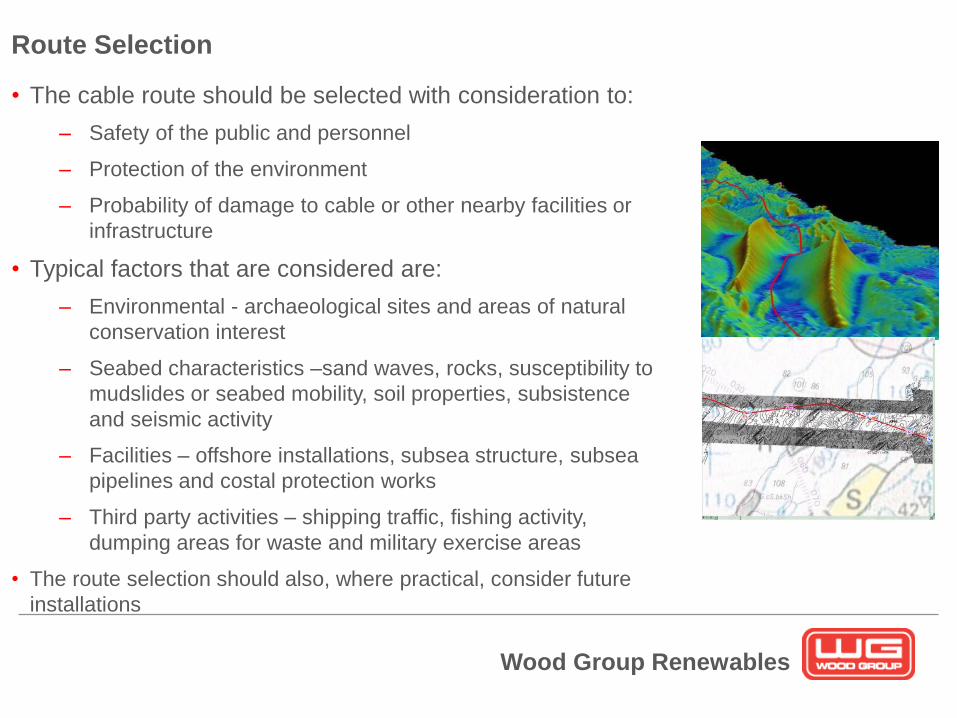
Subsea Cables • The cable route should be selected with consideration to:
– Safety of the public and personnel
– Protection of the environment
– Probability of damage to cable or other nearby facilities or
infrastructure
• Typical factors that are considered are:
– Environmental - archaeological sites and areas of natural
conservation interest
– Seabed characteristics –sand waves, rocks, susceptibility to
mudslides or seabed mobility, soil properties, subsistence
and seismic activity
– Facilities – offshore installations, subsea structure, subsea
pipelines and costal protection works
– Third party activities – shipping traffic, fishing activity,
dumping areas for waste and military exercise areas
• The route selection should also, where practical, consider future
installations
Route Selection

Wood Group Renewables
Subsea Cables
• Route selection is typically undertaken in the following stages:
– Desk Top Study
• Naval charts
• Similar projects in the region
• Seismic data
• Environmental constraints
• Block ownership
• Any other data available
– Route Surveying
• Seabed topography
• Seabed features and obstructions
• Sub-bottom profiling
• Magnetometry used to detect buried cables and other metallic obstructions
– Route Selection and Optimisation
• The preliminary routes are then refined again bearing in mind the Cost, Risk and Impact
Route Selection

Wood Group Renewables
Subsea Cables
• There are fundamentally four different aspects of interest during the cable
installation for an offshore wind farm:
– 1st end pull-in at wind turbine or substation
– Landfall/Shore Approach (export cables)
– Normal cable lay along cable route
– 2nd end pull-in at wind turbine or substation
• Cable lay is undertaken using specialist cable installation vessels with
ROV used to monitor operation subsea
• Installation procedures are typically developed using dynamic analysis to
assess cable integrity throughout proposed operation
Cable Installation

Wood Group Renewables
Subsea Cables
• Installation of cables in the marine environment is significantly more
complex than for onshore cables
– Limited visibility of operation, particularly at regions of interest
– Environmental challenges – depth, waves and current can all restrict
operations
• The cost of cable installation is likely to be more than the cost of cable
itself
– Vessel cost and availability can be highly volatile
Cable Installation
Wood Group Renewables
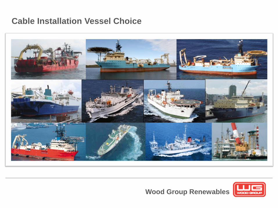
Cable Installation Vessel Choice

Wood Group Renewables
Cable Installation Vessel Choice
Wood Group Renewables
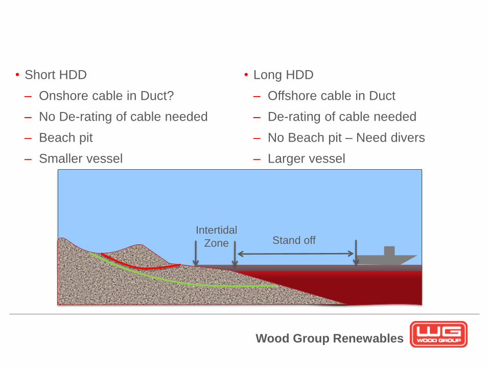
Landfall Construction – HDD
• Short HDD
– Onshore cable in Duct?
– No De-rating of cable needed
– Beach pit
– Smaller vessel
Intertidal
Zone Stand off
• Long HDD
– Offshore cable in Duct
– De-rating of cable needed
– No Beach pit – Need divers
– Larger vessel

Wood Group Renewables
Subsea Cables
• Normal lay of cables is generally well optimised and can be performed with
relative efficiency
• The cable installation is controlled by adjusting the vessel stand-off to alter
the cable tension
– Large stand-off distance - large bend-radius but high tension
– Small stand-off distance – small bend radius but low tension
– High residual tension can minimise potential for compression in cable (from
vessel motion) and provide better touchdown control (prevent loop formation)
– Tension restricted by cable design
• Where seabed condition permit, the cable may be buried simultaneously
using trencher system
Cable Installation – Normal Lay

Wood Group Renewables
Subsea Cables
• For cable trenching, cable is laid within a trench below
the natural seabed
• There are three distinct methods of trenching:
– Ploughing – virtually all soil including friable chalk and
loose rock although efficiency is dependent on
conditions
– Jetting – primarily for granular soil conditions although
also effective in clays
– Cutting – suitable for most conditions although boulder
or flint can significantly increase wear of teeth
Cable Burial - Trenching
Wood Group Renewables
Subsea Cables
• Trenches can be either:
– Pre-formed before the cable is installed
• Allowed to back fill naturally
• Backfilled with imported soil/material
– Formed simultaneously during the cable lay
– Post-formed after the cable is installed
Cable Protection - Trenching
Wood Group Renewables
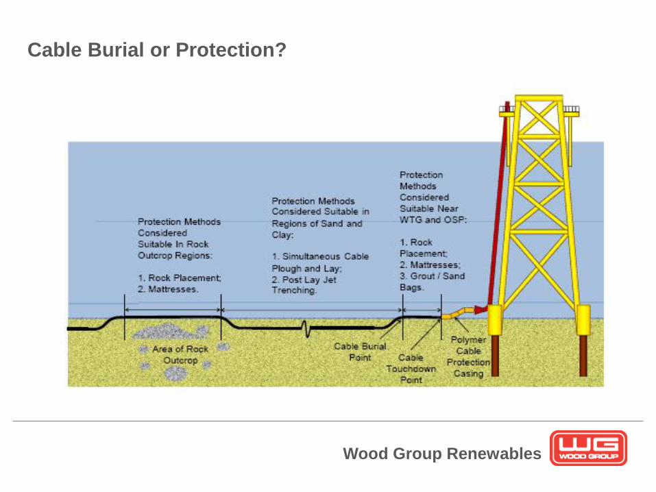
Cable Burial or Protection?
Wood Group Renewables

Wood Group Renewables
Cable Protection
• Rock dump may be needed for
– On-bottom stability
– Freespan correction
– Cable protection
– Scour protection
– Protection/stabilisation
of structures
• Alternatives?
– Mattresses
– Uraduct
– Cast Iron Pipe
– Cable trenching

Wood Group Renewables
Subsea Cables
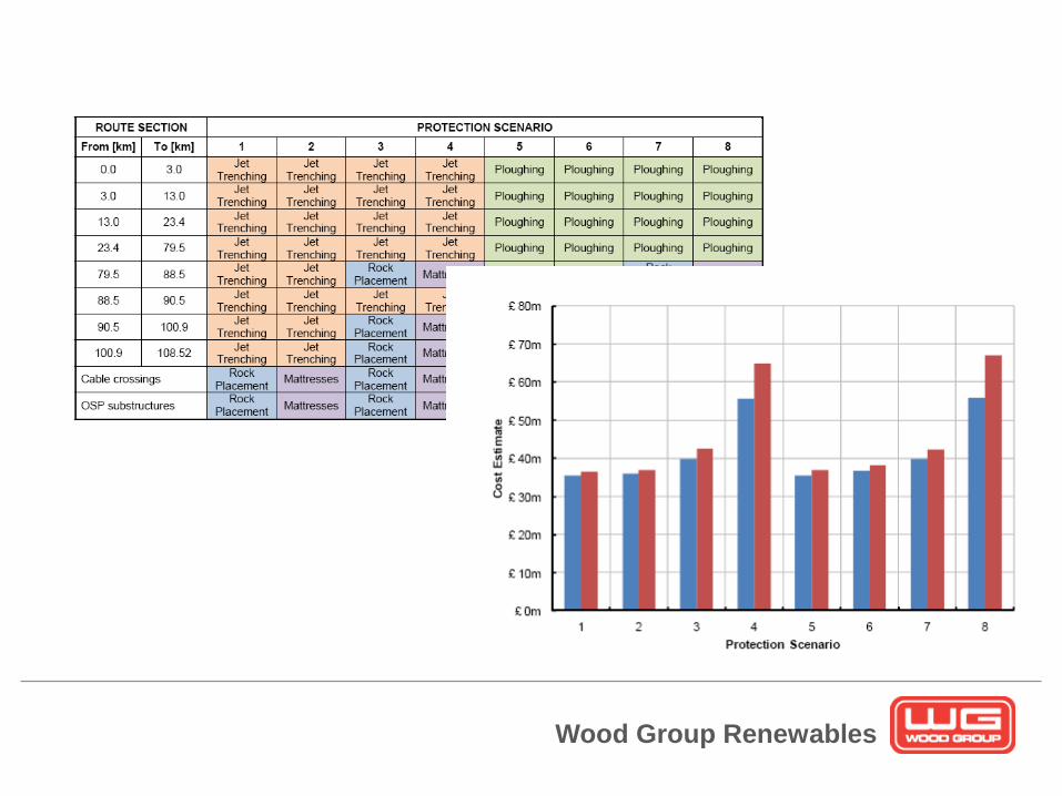
• The main considerations to made when specifying and quantifying rock
dump are as follows:
– Rock size
– Berm size
– Berm weight
• Rock is deployed using specialist rock dumping vessels that either tip rock
directly over the side of the vessel or via a fall pipe
Cable Protection – Rock Dumping
Wood Group Renewables
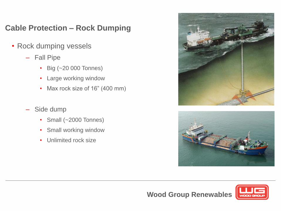
Subsea Cables
• Rock dumping vessels
– Fall Pipe
• Big (~20 000 Tonnes)
• Large working window
• Max rock size of 16” (400 mm)
– Side dump
• Small (~2000 Tonnes)
• Small working window
• Unlimited rock size
Cable Protection – Rock Dumping
Wood Group Renewables
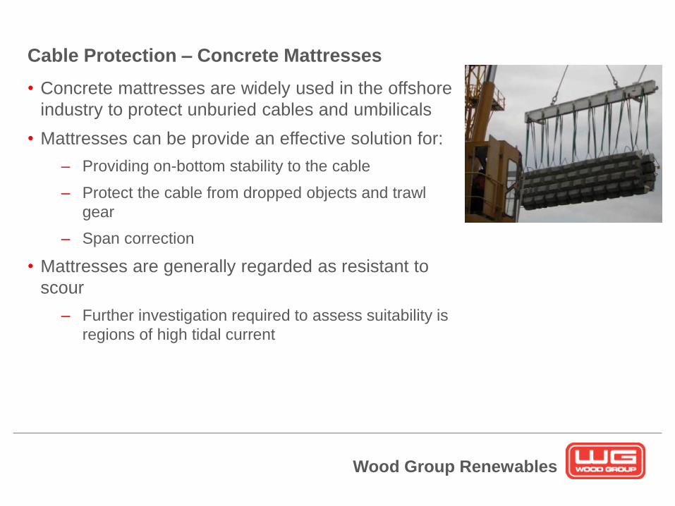
Subsea Cables
• Concrete mattresses are widely used in the offshore
industry to protect unburied cables and umbilicals
• Mattresses can be provide an effective solution for:
– Providing on-bottom stability to the cable
– Protect the cable from dropped objects and trawl
gear
– Span correction
• Mattresses are generally regarded as resistant to
scour
– Further investigation required to assess suitability is
regions of high tidal current
Cable Protection – Concrete Mattresses
Wood Group Renewables
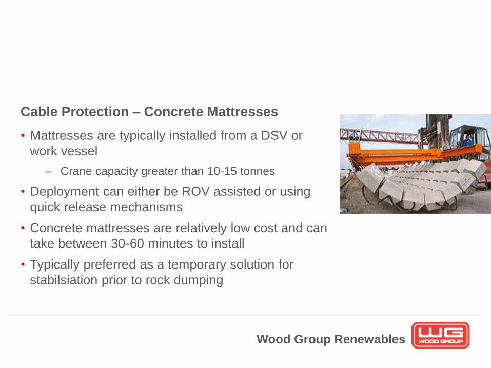
Subsea Cables
• Mattresses are typically installed from a DSV or
work vessel
– Crane capacity greater than 10-15 tonnes
• Deployment can either be ROV assisted or using
quick release mechanisms
• Concrete mattresses are relatively low cost and can
take between 30-60 minutes to install
• Typically preferred as a temporary solution for
stabilsiation prior to rock dumping
Cable Protection – Concrete Mattresses

Wood Group Renewables
Subsea Cables
• Bend stiffeners are used to support cables
connected to rigid structures to prevent over
bending and sometimes fatigue
• Bend stiffeners are conically shaped
mouldings (polyurethane) which increase the
bending stiffness towards the point of fixity
• They are well suited to dynamic applications
such as light cable exposed to the
environment
Cable Protection – Bend Stiffener
• They are not designed to provide protection against dropped object or trawl
gear interaction
Wood Group Renewables
Subsea Cables
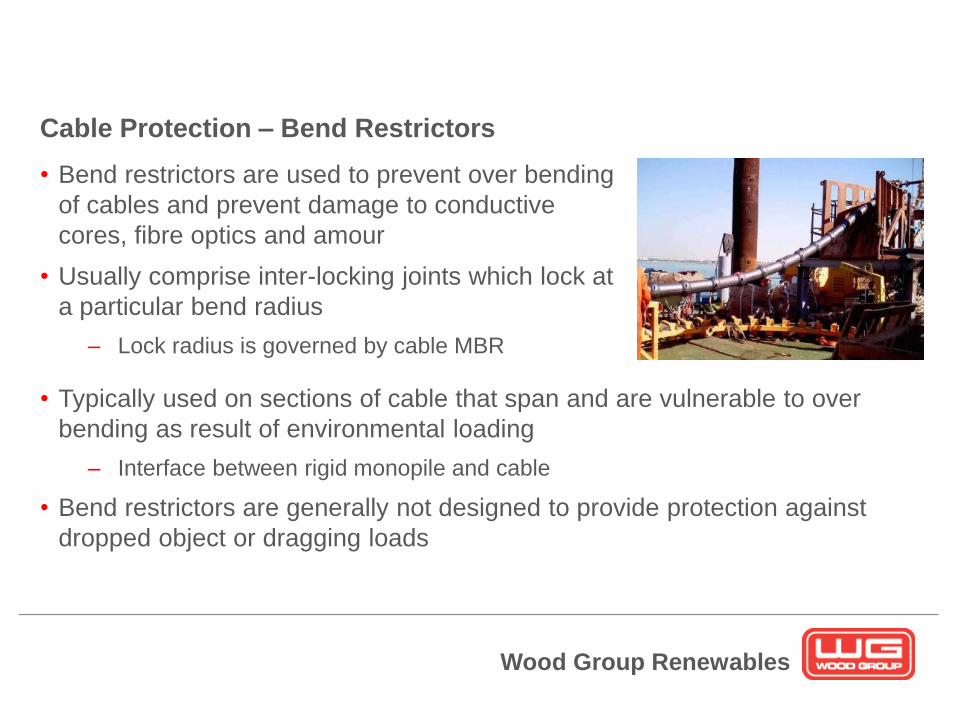
• Bend restrictors are used to prevent over bending
of cables and prevent damage to conductive
cores, fibre optics and amour
• Usually comprise inter-locking joints which lock at
a particular bend radius
– Lock radius is governed by cable MBR
Cable Protection – Bend Restrictors
• Typically used on sections of cable that span and are vulnerable to over
bending as result of environmental loading
– Interface between rigid monopile and cable
• Bend restrictors are generally not designed to provide protection against
dropped object or dragging loads
Wood Group Renewables
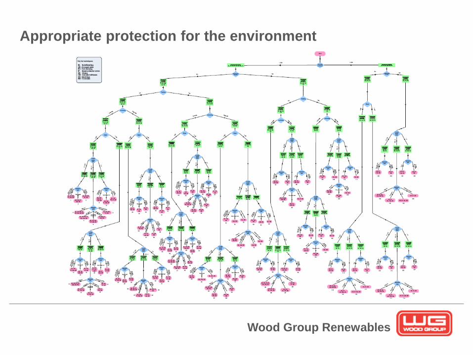
Appropriate protection for the environment

Wood Group Renewables
• Which protection is most suitable?
• What are the residual risks from each type of protection?
• How will this affect installation time?
• What other vessels do you already have on site?
• What is the cost of maintaining the protection?
• Total project cost?
Wood Group Renewables
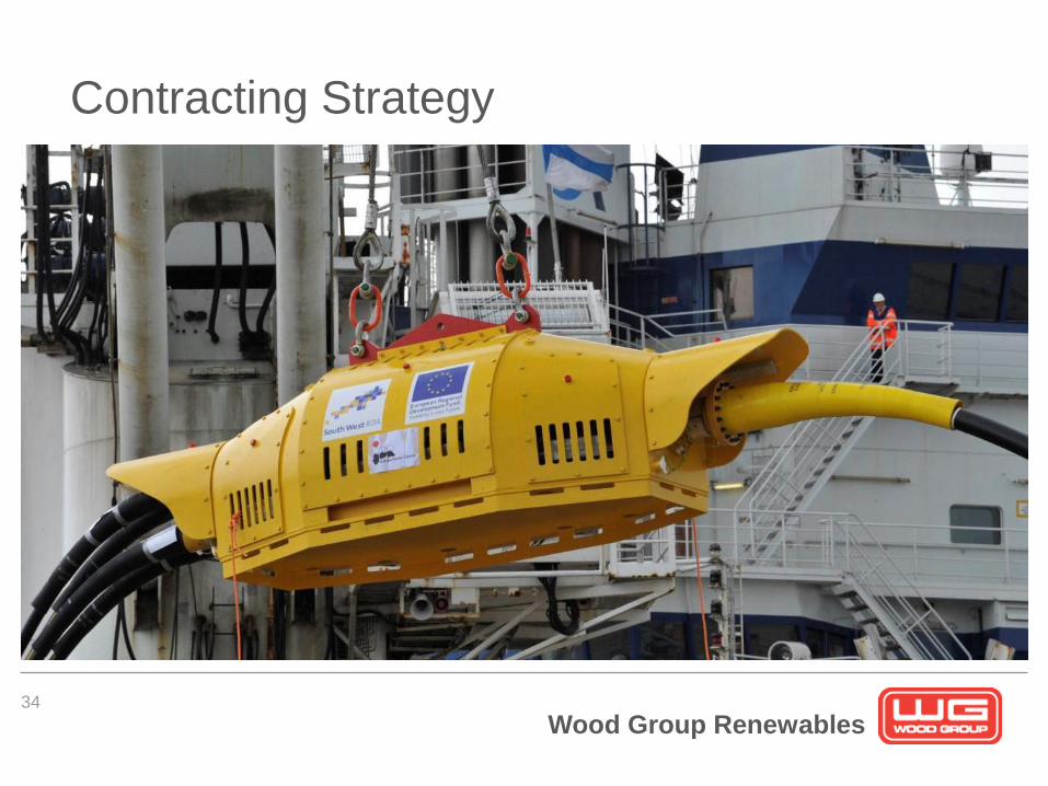
Contracting Strategy
34
Wood Group Renewables
Conclusion
35
•Project risks & costs can be lowered with increased
engineering
•There is no “one size fits all” solution
•Get the right people involved as early as possible in a
project.