Best Operational Practices Manual For Materials Recovery Facilities ...
108
Prepared for: Illinois Recycling Association Funded By: Illinois Department of Commerce and Economic Opportunity November 2010 Best Operational Practices Manual For Materials Recovery Facilities and Recycling Drop-off Facilities WBE/DBE Printedgreen ®
Transcript of Best Operational Practices Manual For Materials Recovery Facilities ...
PPrreeppaarreedd ffoorr:: IIlllliinnooiiss RReeccyycclliinngg AAssssoocciiaattiioonn
FFuunnddeedd BByy:: IIlllliinnooiiss DDeeppaarrttmmeenntt ooff CCoommmmeerrccee
aanndd EEccoonnoommiicc OOppppoorrttuunniittyy
November 2010
BBeesstt OOppeerraattiioonnaall PPrraaccttiicceess MMaannuuaall FFoorr MMaatteerriiaallss RReeccoovveerryy FFaacciilliittiieess aanndd
RReeccyycclliinngg DDrroopp--ooffff FFaacciilliittiieess
WBE/DBE Printedgreen®

PPrreeppaarreedd bbyy:: PPaattrriicckk EEnnggiinneeeerriinngg 330000 WW.. EEddwwaarrddss SStt..,, SSttee.. 220000,, SSpprriinnggffiieelldd,, IILL 6622770044 wwwwww..ppaattrriicckkeennggiinneeeerriinngg..ccoomm AAzzuurree TTeecchhnnoollooggiieess,, IInncc.. 66555577 WW.. NNoorrhhtt AAvvee.. OOaakk PPaarrkk IILL 6600330022 wwwwww..aazzuurree--tteecchh..nneett AAssssuurraannccee SSaaffeettyy CCoonnssuullttiinngg 11775500 EEaasstt GGoollff RRooaadd SScchhaauummbbuurrgg,, IILL 6600117733 wwwwww..aassssuurraanncceessaaffeettyyccoonnssuullttiinngg..ccoomm
November 2010
BBeesstt OOppeerraattiioonnaall PPrraaccttiicceess MMaannuuaall FFoorr MMaatteerriiaallss RReeccoovveerryy FFaacciilliittiieess aanndd
RReeccyycclliinngg DDrroopp--ooffff FFaacciilliittiieess
WBE/DBE Printedgreen®
i
Best Operational Practices Manual
for
Materials Recovery Facilities and Recycling Drop-Off Facilities
TABLE OF CONTENTS
Table of Figures ............................................................................................................................. iii
Acknowledgments ............................................................................................................................ v
1.0 INTRODUCTION ................................................................................................................... 1
2.0 RECYCLING OPERATION INTERVIEWS.......................................................................... 3
3.0 OPTIMIZING EFFICIENCIES IN MRF DESIGN AND OPERATIONS ............................ 11
3.1 LOCATION, SITE CHARACTERISTICS, AND DESIGN EFFICIENCY
CONSIDERATIONS ................................................................................................................ 13
3.2 MATERIALS RECEIVING AND STAGING .................................................................. 18
3.3 MATERIALS SORTING CONSIDERATIONS .............................................................. 21
3.3.1 MANUAL SORTING OF MATERIALS ................................................................... 22
3.3.2 MECHANICAL SORTING OF MATERIALS.......................................................... 27
3.3.3 OPTICAL SORTING OF MATERIALS ....................................................................... 34
3.4 SPECIAL MATERIALS CONSIDERATIONS ................................................................ 37
3.4.1 GLASS RECOVERY AND PROCESSING .............................................................. 37
3.4.2 PLASTICS RECOVERY AND PROCESSING ........................................................ 40
3.4.3 ALUMINUM RECOVERY AND PROCESSING .................................................... 43
3.5 BALING MATERIALS..................................................................................................... 43
3.5.1 PRE-BALING STORAGE ......................................................................................... 43
3.5.2 BALER SELECTION AND OPERATION ............................................................... 44
3.6 PRODUCT STORAGE ..................................................................................................... 47
3.6.1 BALE HANDLING AND STORAGE ....................................................................... 48
3.7 RESIDUALS MANAGEMENT ........................................................................................ 51
3.8 MAINTENANCE .............................................................................................................. 52
3.9 TRANSPORTATION ........................................................................................................ 53
4.0 MARKETING....................................................................................................................... 55
5.0 HEALTH AND SAFETY CONSIDERATIONS ................................................................... 57
6.0 POLLUTION CONTROL AND GOOD NEIGHBOR PRACTICES ................................... 74
7.0 OPTIMIZING DROP-OFF OPERATIONS .......................................................................... 78
8.0 CONCLUSION ....................................................................................................................... 82
APPENDIX A: HEALTH AND SAFETY SELF-ASSESSMENT QUESTIONNAIRE............ 84
APPENDIX B: GLOSSARY OF TERMS .................................................................................. 94
REFERENCES ........................................................................................................................... 100

ii

iii
Table of Figures
TABLE 2.0. FACILITY COMPARISON .................................................................................................................... 3
TABLE 3.1. MRF LOCATION, SITE CHARACTERISTICS AND DESIGN EFFICIENCY Error! Bookmark not
defined. TABLE 3.2. MATERIALS RECEIVING AND STAGING EFFICIENCY CONSIDERATIONS Error! Bookmark
not defined. TABLE 3.3.1.1 MANUAL SORTING EFFICIENCY CONSIDERATIONS ........... Error! Bookmark not defined.
TABLE 3.3.1.2 MANUAL SORTING BENCHMARK SORTING RATES ............. Error! Bookmark not defined.
TABLE 3.3.2. MECHANICAL SORTING OF METALS EFFICIENCYCONSIDERATIONS……………….…..27
TABLE 3.4.1. GLASS RECOVERY AND PROCESSING EFFICIENCY CONSIDERATIONS Error! Bookmark
not defined. TABLE 3.4.2. PLASTICS RECOVERY AND PROCESSING EFFICIENCY CONSIDERATIONS ............. Error!
Bookmark not defined. TABLE 3.5. BALING EFFICIENCY CONSIDERATIONS ..................................... Error! Bookmark not defined.
TABLE 3.6. PRODUCT STORAGE CONSIDERATIONS ...................................... Error! Bookmark not defined.
TABLE 3.9. TRANSPORTATION CONSIDERATIONS ........................................ Error! Bookmark not defined.
TABLE 4.0. MARKETING CONSIDERATIONS .................................................................................................... 55
TABLE 6.0. POTENTIAL IMPACTS ON NEIGHBORS AND MITIGATION MEASURES ................................ 76

iv

v
Acknowledgments
The Illinois Recycling Association and Patrick Engineering would like to thank the following
persons for their assistance in providing review, comments and input on early drafts of this
document (in alphabetical order).
Steve Apotheker, Metro
Chad Braatz, Tri-Co. Resource & Waste Mgmt. Council
Bart Hagston, Jackson County Health Department
Paul Jaquet, Eagle Enterprises Recycling Inc.
David Kramer, Illinois Department of Commerce and Economic Opportunity (OSHA)
Greg Maxwell, Resource Management
David Smith, Illinois Department of Commerce and Economic Opportunity (Recycling)
We would also like to thank the recycling facility operators who participated in this study by
taking time out of their busy days to fill out a lengthy survey, conduct tours of their facilities, and
answer our endless questions.

vi

1
1.0 INTRODUCTION
The Illinois Recycling Association (IRA) is pleased to provide this Best Operational
Practices Manual (BOPM) as a tool to further advance professional recycling in Illinois. IRA
gratefully acknowledges the Illinois Department of Commerce and Economic Opportunity who
provided funding for the development of this manual and their continuing support for recycling
in Illinois
Over the last two decades contemporary recycling has witnessed many changes in
collection, processing and marketing of commodities. There are different processing systems
that operate as a function of the differing collection systems that are in place or being considered.
Furthermore, increases in the types and quantities of commodities recovered in existing or new
programs may require facility technology and equipment retrofits. The purpose and intent of this
manual is to assist those Illinois counties, cities and businesses that own/operate materials
recovery facilities (MRFs) and recycling drop-offs to evaluate their operations in accordance
with Best Operational Practices (BOPs) to reduce negative environmental impacts, advance
safety consciousness, improve processing efficiencies, reduce operating costs, and increase the
potential to improve revenues for the materials recovered. This manual describes systems and
procedures that can be employed by recycling facilities to operate as successful commodities
businesses without the need for any special or environmental protection permits.
The guide addresses operations of facilities that accept materials intentionally separated
from the commodity/waste stream by the generators for the purpose of recycling. Although there
are some commonalities in their operations, it does not include transfer stations, resource
recovery facilities or so-called ―dirty‖ MRFs, which may separate recyclable materials from
mixed waste.
Eleven recycling facility operators
across the state of Illinois were
interviewed to bring practical
experience and practicable
recommendations to this manual.
Section 2 summarizes the results of
these interviews.
Section 3 takes the findings
of the individual interviews, as well
as other documented BOPs from
other MRFs and industry sources,
and lays out the concepts and practices that contribute to improved processing efficiencies,
reduced operating costs, and increased revenues from the sale of recovered materials. Though
not applicable to all situations, most MRFs using this guide should find useful ideas and
practices that will help improve their overall operations. Section 4 discusses maintenance issues.
Section 5 reviews the health and safety issues that a recycling facility operator may encounter
and a self-assessment checklist is provided as an appendix to help evaluate compliance with
safety and health standards. Section 6 discusses good neighbor practices and environmental
considerations. Section 7 discusses drop-off operations.

2

3
2.0 RECYCLING OPERATION INTERVIEWS
TABLE 2.0. FACILITY COMPARISON
Facility
# Type Ownership
Approx.
size
(Tons/Mo.)
Input Stream Comm./
Resid.
Employees
(full/part/vol)
Began
Operation
1 MRF Private 14,000
90% single
stream, 10%
separated
15% /
85% 69/0/0 1997
2 MRF Private 7000
99% single
stream, 1%
separated.
0% /
100% 60/0/0
3 MRF Private 9900
81.5% single
stream/ 14%
dual/ 4.5%
separated
18.5% /
81.5% 90/0/0 1997
4 MRF/Drop-
off Private 125
Source
separated
80% /
20% 6/4/2 1995
5 MRF Private 2000
6 MRF Private 400
Approx equal
single, dual and
separated
5% /
95% 11/3/0 1973
7 MRF Private 220
45% single
stream/ 55%
separated
55% /
45% 3/1
8 MRF/Drop-
off
Not-for-
Profit 1000
Source
separated
60% /
40% 3/2/4 1988
9 MRF/Drop-
off Public 90
3% single
stream / 97%
separated
60% /
40% 4/1/0
10 MRF/Drop
off Private Dual stream 13/4/0
11 Drop-off Public/
private 12-17 Single stream
75% /
25% 1/0/0 1992
(Notes: vol = volunteers)
Facility 1. Facility 1 was the largest and most fully automated of the MRFs visited.
Located in Northeastern Illinois, it processes primarily single-stream recyclables from residential
curbside programs and operate two shifts daily. The facility is still expanding and is in the
process of installing additional sorting lines.
Incoming materials are dumped on a large tip floor where a wheel loader is used to move
the mixed recyclables to an inclined conveyor which feeds a presort conveyor. The loader also
mixes incoming loads in order to help provide a consistent feed down the line. Four sorters then
remove bulky items, garbage and other throw-outs and open and remove plastic bags. From
there, materials pass over a disk screen which separates OCC and then over a series of three
finger-disk screens which separate out the containers and direct two streams of paper to an upper
4
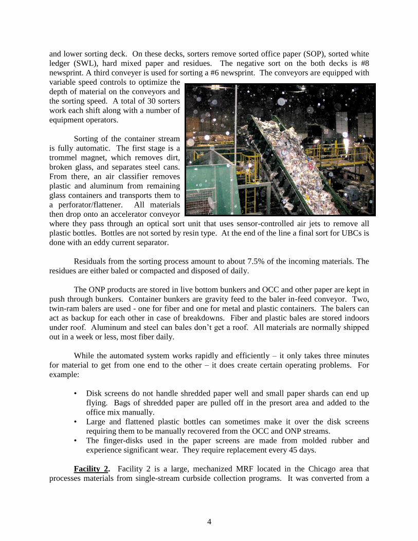
and lower sorting deck. On these decks, sorters remove sorted office paper (SOP), sorted white
ledger (SWL), hard mixed paper and residues. The negative sort on the both decks is #8
newsprint. A third conveyer is used for sorting a #6 newsprint. The conveyors are equipped with
variable speed controls to optimize the
depth of material on the conveyors and
the sorting speed. A total of 30 sorters
work each shift along with a number of
equipment operators.
Sorting of the container stream
is fully automatic. The first stage is a
trommel magnet, which removes dirt,
broken glass, and separates steel cans.
From there, an air classifier removes
plastic and aluminum from remaining
glass containers and transports them to
a perforator/flattener. All materials
then drop onto an accelerator conveyor
where they pass through an optical sort unit that uses sensor-controlled air jets to remove all
plastic bottles. Bottles are not sorted by resin type. At the end of the line a final sort for UBCs is
done with an eddy current separator.
Residuals from the sorting process amount to about 7.5% of the incoming materials. The
residues are either baled or compacted and disposed of daily.
The ONP products are stored in live bottom bunkers and OCC and other paper are kept in
push through bunkers. Container bunkers are gravity feed to the baler in-feed conveyor. Two,
twin-ram balers are used - one for fiber and one for metal and plastic containers. The balers can
act as backup for each other in case of breakdowns. Fiber and plastic bales are stored indoors
under roof. Aluminum and steel can bales don‘t get a roof. All materials are normally shipped
out in a week or less, most fiber daily.
While the automated system works rapidly and efficiently – it only takes three minutes
for material to get from one end to the other – it does create certain operating problems. For
example:
• Disk screens do not handle shredded paper well and small paper shards can end up
flying. Bags of shredded paper are pulled off in the presort area and added to the
office mix manually.
• Large and flattened plastic bottles can sometimes make it over the disk screens
requiring them to be manually recovered from the OCC and ONP streams.
• The finger-disks used in the paper screens are made from molded rubber and
experience significant wear. They require replacement every 45 days.
Facility 2. Facility 2 is a large, mechanized MRF located in the Chicago area that
processes materials from single-stream curbside collection programs. It was converted from a
5
dual-stream system in the year 2000, and went to a double-shift to handle the extra processing
and materials.
From the tip floor, a wheel-loader moves incoming material to an inclined conveyor,
which feeds a presort line. The loader tries to keep material spread out so it isn‘t mounded on
the presort line. On the presort line, eight sorters open bags and remove refuse and OCC.
Two star-disk screens then separate ONP from the mixed paper and containers, which is
then positively sorted manually for quality control to produce a #8 newsprint. A third disk
screen, angled and inclined, sends mixed paper over the top and containers off one side while
glass falls through. The mixed paper is also positively sorted. A total of 11 sorters work the
three paper lines.
The container stream passes through one more disk screen to remove fines and any
remaining glass. Four sorters then separate plastics by type, followed by a magnetic cross belt to
remove steel cans. An eddy current separator does a final positive sort for aluminum.
The burden depth on the sorting conveyors is controlled by variable speed drives. The
bunkers under the paper lines have in-bottom conveyors, which directly feed the baler in-feed
conveyor. The container bunkers have sloped bottoms that allow them to gravity-feed the baler
conveyor. A single, fully automatic, high volume baler is used for all materials.
All baled materials are stored indoors. Glass is stored loose in an outdoor bunker.
Residues from the sorting lines are stored in two compactors, which are dumped once or twice a
shift. Residual rates run about six percent.
The operator finds labor costs to be high for this facility and would like to add additional,
technologically advanced equipment to reduce labor and processing costs.
Facility 3. Facility 3 is another large MRF located in the greater Chicago area and is co-
located with a transfer station, though the operations are separate. The facility processes
materials that the company collects by providing single-stream, curbside collection services to 20
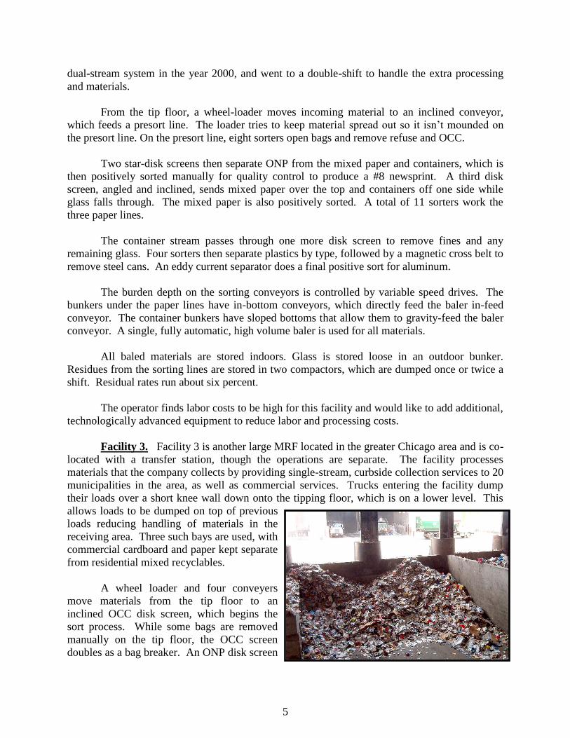
municipalities in the area, as well as commercial services. Trucks entering the facility dump
their loads over a short knee wall down onto the tipping floor, which is on a lower level. This
allows loads to be dumped on top of previous
loads reducing handling of materials in the
receiving area. Three such bays are used, with
commercial cardboard and paper kept separate
from residential mixed recyclables.
A wheel loader and four conveyers
move materials from the tip floor to an
inclined OCC disk screen, which begins the
sort process. While some bags are removed
manually on the tip floor, the OCC screen
doubles as a bag breaker. An ONP disk screen

6
follows the OCC screen. A final, tilted and inclined disk screen separates the remaining paper
over the top, cans and plastic bottles off the side and glass and other residues through the bottom.
All the feed conveyers, screens and sorting conveyers are variable speed. The three paper
streams (OCC, ONP and other) are negatively sorted manually for quality control to produce
clean OCC, #8 and #6 Newsprint, sorted office paper, and mixed paper. Eleven to twelve sorters
work the paper lines. Shredded paper is not processed through the sorting line but is kept
separate and added to the office paper before baling.
The glass is sent through a final trommel and is sold as mixed broken glass. The
commingled metal and plastic containers are not sorted on-site, but are transferred to another
MRF where they are processed under contract for $140/ton (April 2005) minus the market value
of the sorted materials.
A redundant pair of two-ram balers is used to bale paper. Paper storage bunkers feed
directly to the balers through chutes that are controlled remotely from a central location. All
bales are stored indoors and are shipped to market within 1-3 days.
Residue rates for Facility 3 vary from 7 to 12 percent and are a concern for the facility
manager. Even with the transfer station on-site, the cost of disposing of residues is high in this
area. If too many recyclables are observed in the residuals, they are reprocessed. If commercial
loads contain too many contaminants, the customer receives a charge for trash disposal.
Facility 4. Facility 4 is located in a small town in western Illinois and provides all the
recycling services for the town and some of the surrounding areas. It operates a source-separated
curbside collection program for about 3500 households and a drop-off at the main location. A
mobile drop-off is also staffed at a nearby community two Saturdays a month. The main drop-
off is open 7a.m.-5p.m. on weekdays and 8a.m- noon on Saturdays. Users drive up to the main
entrance and staff will unload their vehicles and hand sort the recyclables inside the building.
Unacceptable materials remain in the vehicles. They claim their users have become very good
about knowing what they can and cannot drop off.
However, the bulk of their business is commercial materials, with cardboard from a local
food packing plant their biggest account. They also handle used clothing from a charitable reuse
operation in town. It is interesting to note, that since they were storing bales of clothing for long
periods to get shippable quantities, there was concern about mice nesting in the bales. Adding a
cat to the staff solved the problem.
Most of the pre-baling storage is done in gaylords or similar containers. Glass is sorted
by color and crushed. Plastic bottles are sorted into natural and colored HDPE and PET and
baled using dedicated vertical balers for each. Final contamination control is done as the balers
are loaded.
Paper, OCC and metals are baled in a large horizontal baler. In a somewhat unique
situation, this position was formerly held by an agricultural hay baler with hay chopper and fed
by a manure spreader acting as a conveyor. The chopper and manure spreader are still in use
feeding the in-feed conveyor to the baler. Magazines, steel and aluminum cans get a final
7
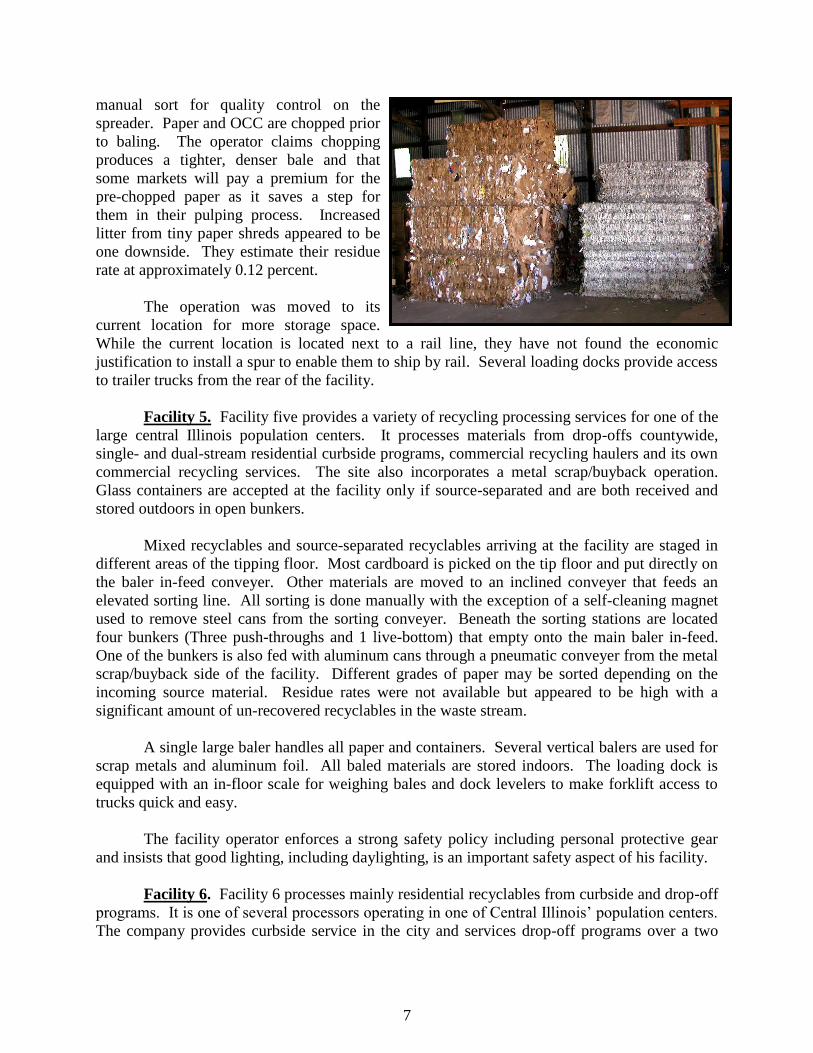
manual sort for quality control on the
spreader. Paper and OCC are chopped prior
to baling. The operator claims chopping
produces a tighter, denser bale and that
some markets will pay a premium for the
pre-chopped paper as it saves a step for
them in their pulping process. Increased
litter from tiny paper shreds appeared to be
one downside. They estimate their residue
rate at approximately 0.12 percent.
The operation was moved to its
current location for more storage space.
While the current location is located next to a rail line, they have not found the economic
justification to install a spur to enable them to ship by rail. Several loading docks provide access
to trailer trucks from the rear of the facility.
Facility 5. Facility five provides a variety of recycling processing services for one of the
large central Illinois population centers. It processes materials from drop-offs countywide,
single- and dual-stream residential curbside programs, commercial recycling haulers and its own
commercial recycling services. The site also incorporates a metal scrap/buyback operation.
Glass containers are accepted at the facility only if source-separated and are both received and
stored outdoors in open bunkers.
Mixed recyclables and source-separated recyclables arriving at the facility are staged in
different areas of the tipping floor. Most cardboard is picked on the tip floor and put directly on
the baler in-feed conveyer. Other materials are moved to an inclined conveyer that feeds an
elevated sorting line. All sorting is done manually with the exception of a self-cleaning magnet
used to remove steel cans from the sorting conveyer. Beneath the sorting stations are located
four bunkers (Three push-throughs and 1 live-bottom) that empty onto the main baler in-feed.
One of the bunkers is also fed with aluminum cans through a pneumatic conveyer from the metal
scrap/buyback side of the facility. Different grades of paper may be sorted depending on the
incoming source material. Residue rates were not available but appeared to be high with a
significant amount of un-recovered recyclables in the waste stream.
A single large baler handles all paper and containers. Several vertical balers are used for
scrap metals and aluminum foil. All baled materials are stored indoors. The loading dock is
equipped with an in-floor scale for weighing bales and dock levelers to make forklift access to
trucks quick and easy.
The facility operator enforces a strong safety policy including personal protective gear
and insists that good lighting, including daylighting, is an important safety aspect of his facility.
Facility 6. Facility 6 processes mainly residential recyclables from curbside and drop-off
programs. It is one of several processors operating in one of Central Illinois‘ population centers.
The company provides curbside service in the city and services drop-off programs over a two

8
county area. They also accept materials from other private haulers. Recyclables are received
both sorted and unsorted. The materials acceptance policy is especially broad in that all fiber, all
metals, all plastics and three colors of glass are accepted.
All materials are hand sorted starting with OCC and bundled ONP, which are picked off
the tip floor into three cubic yard dumpsters. A skid steer is used to load the remaining materials
into a hopper, which feeds a short sorting line. The sorters start and stop the belt to load it in
batches and positively sort all recyclables into containers. Residuals amount to about 5 percent
of the materials received.
Prior to baling, plastic bottles are stored in six cubic yard nylon bags and other materials
in dumpsters. All materials except glass are baled. Sorted glass is stored in gaylord boxes but is
not crushed. Sorters were observed throwing bottles into sorting containers to manually break
glass. Since the facility suffers from a lack of indoor space, all sorted materials are stored
outdoors, with fiber and plastic bales and gaylord boxes under tarps. There is no loading dock at
the facility.
The operator is in the planning stage of a major expansion of Facility 6 to include a large
increase in floor space and storage bunkers or silos for sorted materials to help eliminate double
handling and lean-to structures for covered storage. With these improvements he plans to
significantly increase his throughput with no increase in labor.
Facility 7. Facility 7 operates and receives materials from a single-stream curbside
collection program in one of the middle-sized population centers in central Illinois. They also
receive materials from commercial accounts and from drop-off boxes from surrounding
communities.
Facility 7 has recently mothballed its sorting line in favor of an agreement with a much
larger MRF in Northeastern Illinois. All commingled recyclables, including glass, from the
curbside and drop-off programs are loaded, loose and unprocessed, into a transfer trailer for
shipment to the larger MRF. They are paid at a rate averaging about $33 a ton (March 2005).
Materials from their commercial
accounts consist primarily of paper, OCC, and
chipboard and bookbindery cuttings, which are
source separated. The commercial paper is
stored and shipped in gaylords. OCC is baled
in a horizontal baler and the cuttings are baled
in a high-density vertical baler. OCC bales are
stored outdoors.
The operator wishes to eventually
remove the sorting line and a compactor that
was previously used for residues, and install a
pit and loading dock to make loading the transfer trailer easier and more efficient. A loading
dock is currently in use but it is not attached to the building, making loading weather-dependent.
9
Facility 7 is located alongside a rail line, but it does not have the volumes that would make rail
shipment practical.
Facility 8. Facility 8 is a not-for-profit operation located in a large, mostly rural county
in southwestern Illinois. The facility operates both as the recycling drop-off for the largest city
in the county and as a processing center, accepting recycling trailers from other communities.
They also operate a subscription (fee) residential curbside collection program, collect from
commercial accounts and provide several surrounding communities with ―Drop-off Saturday‖
collections. The curbside program serves 170 households and represents about 10% of their
incoming material. The organization also operates drop-off and processing operations in two
other towns in the county. They collect and process cardboard, magazines, newspaper, office
paper, aluminum and steel cans, glass and plastic containers and scrap aluminum at each
location.
The drop-off is staffed 8-5 on weekdays but is open to the public 24/7. Two cubic-yard,
self-dumping hoppers are the primary collection containers. Dumping of trash has not been a
severe problem but they do occasionally receive unwanted materials. Since all the material the
MRF receives is source-separated, there is no sorting line, however employees routinely monitor
drop-off bins and the conveyor to the horizontal baler and remove unwanted materials. Their
residual rate is estimated at less than 5 percent.
All materials except glass are baled. Glass is sorted into clear and mixed, and crushed.
Their market for clear glass requires no caps or rings, but manually removing caps and rings
proved too labor intensive. So clear bottles with caps or rings are added to the mixed glass
stream.
With the exception of OCC and steel cans, baled materials are stored indoors. OCC and
steel cans are moved to market rapidly enough to avoid weather-related degradation. Though the
facility achieves a good throughput for its size, they have had to hold some materials for an
extended time to achieve transportable quantities. For example, they can go over a year between
shipments of mixed plastic bales.
Improvements that are planned for Facility 8 include expanding the storage building,
improving the drainage and surfaces of the driveways, parking and shipping areas, and
establishing a regular schedule of operations. The facility has a portable loading dock and has
just recently added a second permanent dock.
Facility 9. Facility 9 is a county-owned and operated MRF and drop-off that provides
recycling services to a large rural county in southwestern Illinois. The facility is subsidized by
landfill tipping fee surcharge funds. In addition to drop-off collection at the facility, they also
provide commercial collection in two cities and service drop-off locations in five other
communities. The drop-off is open to the public at all times but staff is only available during the
MRF operating hours. They accept a variety of fiber products, metals and #1 and #2 plastics, but
no glass. Gaylords are used as drop-off containers and for storage of materials prior to baling.
Some commercial customers have their own small balers and some paper and OCC arrives pre-

10
baled. They do not often re-bale these
materials. The operator has made personal
visits to customers if contamination levels
get too high. Residuals are estimated at
about two percent.
They do very little sorting, except
for contamination control on the baler in-
feed, but do bale several different grades of
paper. Plastics are baled mixed. Sorting
HDPE from PET manually did not prove
economical. All materials are stored inside
the building, where a ramp leads to a single loading dock. Like most, this operator wanted more
storage space.
Facility 10. Facility 10 is a regional processing facility in southern Illinois that handles
materials from dual-stream residential collection programs, drop-off facilities and commercial
collection programs. This facility incorporates an indoor drop-off and electronics waste drop-off
and was the smallest visited that had its own truck scales.
Paper and commingled containers are received on different tip floors. There is no sorting
line for paper except to separate cardboard on the tip floor, but different grades of paper may be
baled depending on incoming material. Commingled containers are moved to an elevated sorting
line where all containers are positively sorted. First, plastics are sorted manually, after which a
cross-belt magnet removes steel cans. Sorters then remove glass containers, and finally
aluminum is removed with an eddy current separator. Residue rates were not available but they
appeared to be high with a significant amount of un-recovered recyclables in the waste stream.
Containers are stored in inclined bottom cages, which are moved to the baler when full.
One baler is used for all containers and paper and a second is reserved for OCC. A small vertical
baler, located near the drop-off, is used to recover plastic film and bags.
All materials are stored indoors or in staged trailers. The facility has five loading docks
available. The facility also has a rail spur available but it is not currently in use.
Facility 11. Facility 11 is a staffed drop-off located in a large urban community in
northeast Illinois. A curbside collection program already services the community, but the drop-
off is provided to service apartment dwellers and small businesses. While located on public
property, a private recycler manages all operations. An area MRF operator sites two, 30 cubic
yard roll-offs for paper and containers and provides the attendant, and a local scrap dealer spots a
dumpster for bulky scrap metal. The MRF operator also provided site improvements including
concrete paving. The location is fenced and is open Tuesday, Thursday and Saturday from 8
a.m. to 4 p.m. The attendant helps people unload their vehicles, watches for unwanted materials
and litter, and answers questions and hands out flyers to those who bring material. Residue rates
from the drop-off are estimated at less than two percent.

11
3.0 OPTIMIZING EFFICIENCIES IN MRF DESIGN AND OPERATIONS
One of the goals of this manual is to take the knowledge gained in the facility assessments,
combine it with other ―best management practices‖ from within the industry, and develop a
guide that other facilities, both public and private, can consider to improve operations.
It is important that recycling facilities accept only materials that have been specifically separated
from the waste stream by the generators for recycling. Facilities that accept commodities that
contain a ―high‖ level of contaminants could be subject to extensive regulatory permits and
oversight. Therefore facilities should work cooperatively with haulers and/or local governments
to maintain an acceptable level of public education so that participants are aware of what
commodities are acceptable and which are not. This section presents systems, procedures and
practices that should be considered to optimize efficiencies in design and operations. (In this
instance ―source-separated‖ is not used to distinguish between recycled material collection
methods, as in the previous section, but means commodities that have been intentionally
separated from the waste by generators.) Essential best practices include the following:
1. Have systems and procedures in place to identify and confirm that only source-separated
commodities are delivered to the MRF.
2. Incorporate operational efficiencies to achieve processing of commodities in the most
economical manner.
3. Maintain operational effectiveness to ensure that commodities are recovered to meet
market specifications.
4. Have operational adaptability to adjust processing systems and procedures to process and
market commodities to sustain operational efficiencies and effectiveness.
Operational efficiency centers on the use of resources (labor and capital) in sorting and
processing materials delivered to the MRF. Operational efficiency focuses on reducing sorting
and processing costs while still maintaining (or increasing) the desired throughput of materials.
Improved efficiencies can be implemented with a short-term return on investment in mind
(removing plastic film at the beginning of a sort line to aid in seeing and capturing more
recoverable materials down the line) or with a more long-term return on investment in mind
(purchasing a baler to achieve a higher revenue for the materials sold and to reduce
transportation costs for getting materials to market).
Producing the desired result and meeting customer expectations is an example of
operational effectiveness. As it applies to a MRF, this can be equated to maintaining or
improving the product quality of commodities sold to markets. Often this translates to higher
revenues, positive long-term relationships with markets, and a decreased potential for a reduction
in market revenues or having commodities rejected. Operational effectiveness can also be
applied on a micro level within an operation. For example, training line workers to do a good job
in sorting will improve the quality of the materials sent to the baler. This in turn will help
improve the efficiencies in the baling operation with less time spent sorting contaminants out of
commodities being baled or having to re-bale commodities to meet market specifications.
12
Operational adaptability refers to the ability to adapt to changing customer or business
needs.
One example is the changing on the structure of recycled fibers at the MRF. On its
January 2010 issue, Resource Recycling editorialized about the decline of the printed media,
both in advertising and number of pages in newspapers and magazines.
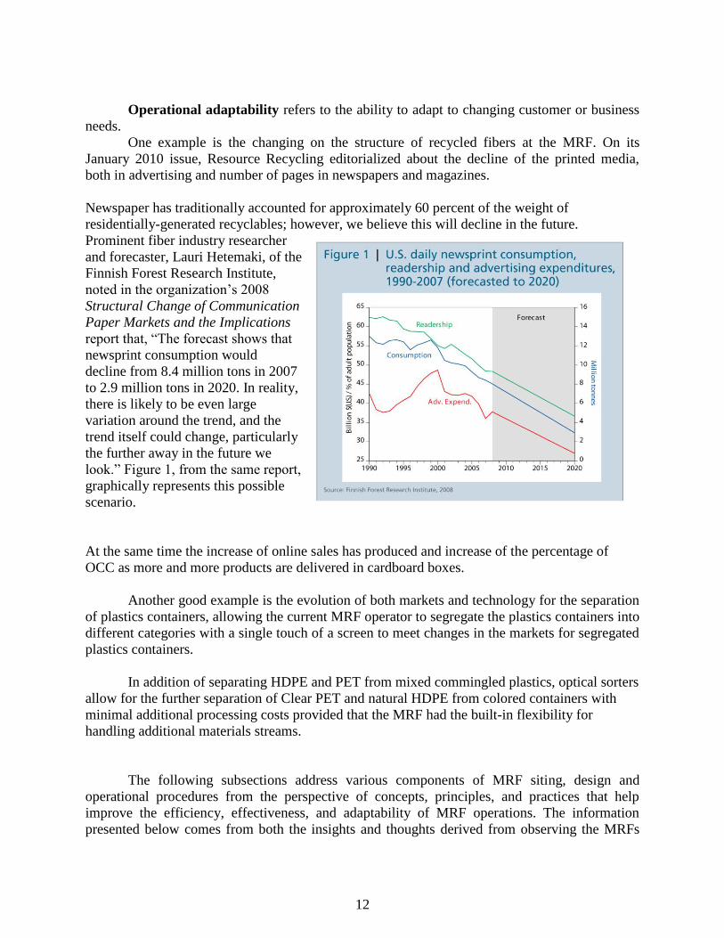
Newspaper has traditionally accounted for approximately 60 percent of the weight of
residentially-generated recyclables; however, we believe this will decline in the future.
Prominent fiber industry researcher
and forecaster, Lauri Hetemaki, of the
Finnish Forest Research Institute,
noted in the organization‘s 2008
Structural Change of Communication
Paper Markets and the Implications
report that, ―The forecast shows that
newsprint consumption would
decline from 8.4 million tons in 2007
to 2.9 million tons in 2020. In reality,
there is likely to be even large
variation around the trend, and the
trend itself could change, particularly
the further away in the future we
look.‖ Figure 1, from the same report,
graphically represents this possible
scenario.
At the same time the increase of online sales has produced and increase of the percentage of
OCC as more and more products are delivered in cardboard boxes.
Another good example is the evolution of both markets and technology for the separation
of plastics containers, allowing the current MRF operator to segregate the plastics containers into
different categories with a single touch of a screen to meet changes in the markets for segregated
plastics containers.
In addition of separating HDPE and PET from mixed commingled plastics, optical sorters
allow for the further separation of Clear PET and natural HDPE from colored containers with
minimal additional processing costs provided that the MRF had the built-in flexibility for
handling additional materials streams.
The following subsections address various components of MRF siting, design and
operational procedures from the perspective of concepts, principles, and practices that help
improve the efficiency, effectiveness, and adaptability of MRF operations. The information
presented below comes from both the insights and thoughts derived from observing the MRFs

13
participating in this study as well as other best management practices from within the industry.
Not every item discussed below will be applicable in all situations. The intent of the IRA is that
all facilities receiving this guide will find some useful suggestions or validation of methods that
improve operations.
3.1 LOCATION, SITE CHARACTERISTICS, AND DESIGN EFFICIENCY
CONSIDERATIONS
Siting and designing a materials recovery
facility should be undertaken with efficiency
and operational safety considerations in mind.
This means addressing such issues as
location, site characteristics, local zoning and
permitting requirements, facility design and
layout, process/operational flow,
employee/visitor safety; and - if a MRF is going to be placed into an existing structure or added
onto a transfer station or WTE facility - the characteristics of existing buildings.
Incorporating these items into the planning process will provide both short-term and
long-term economic and safety benefits. The location, site characteristics and design efficiency
considerations discussed below are not all inclusive nor will they be applicable in all situations.
However, the considerations outlined in Table 3.1 will provide some guidelines in the upfront
planning process when a MRF is being considered.

14
TABLE 3.1. MRF LOCATION, SITE CHARACTERISTICS AND DESIGN EFFICIENCY
Considerations Concepts/Principles/Practices Potential Benefits/Comments
Location-Materials: The facility should be located in
close proximity to population centers and the collection
sources.
Minimizes transportation distances to and from the
collection sources. This leads to less time spent servicing
routes, a reduction in vehicle fuel consumption in getting
materials from generation sources to the processing
facility, and less wear and tear on collection vehicles.
This concept is particularly valid when the same entity
that owns the facility provides for collection services but
is also valid for merchant facilities that want to attract
the business of others providing the collection service.
However, some larger facilities can receive materials
from long distances away via transfer trailers.
Location-Roads: The facility or site for a proposed
facility should be located near major highways or other
transportation arterials, and provide for easy
access/egress to the facility.
Location on major transportation routes and easy
access/egress to the site will add to convenience and
efficient delivery of materials to the site as well as
shipment of process materials to market. Additional
benefits may include less road weight and vehicle
restrictions, and easier access for emergency vehicles in
case of fire, police, or health emergencies.
On-site Traffic: On-site roadway system should
minimize the number of traffic intersections and merges.
To the extent possible keep personal vehicle traffic,
material delivery traffic, and tractor-trailer traffic
separate.
Efficiently moves traffic on and off site and will add to
safety of site personnel, customers, and visitors.
Codes: The site and/or building should meet local
zoning requirements and fit in with surrounding land
uses.
Less time and cost involved in obtaining local permits
and approvals.
Site acreage should be large enough to accommodate
the physical structure, outside storage space for
materials and/or equipment, sufficient space for safe and
orderly vehicle movement (including vehicles delivering
materials, tractor-trailers moving materials to markets,
and employee/visitor parking), potential expansion area,
and buffer areas (either natural or manmade) to adjacent
properties.
Sufficient space for all the activities occurring at a MRF
is crucial. A site that is too small will add to safety
concerns, inefficient processing and movement
activities, potential environmental and aesthetic
concerns with neighbors, and limited space for
processing and storage Limited processing space will
impact not only the quantities of materials processed but
also the adaptability of the facility. Insufficient storage
space will limit how long finished product can be stored
before marketing and could lead to product quality
issues and diminished revenues.
Utilities: If not already present, the site should have
close access to utilities (water, sewer, power, phone). If
utilities are already on-site determine the adequacy and
potential upgrades to those utilities.
Is the wastewater collection and treatment system (on-
site and off site) capable of handling and permitted to
handle the wastewater coming from this type of
operation? Is the electrical service at the facility
appropriately sized for the type and size of equipment
that will be used in the operation?
Controlled Access: If the site does not have restricted
access from neighboring properties or frontage roads,
security fencing or other barriers should be placed
around the property perimeter.
Controlling access to the site is important for both
operational and liability issues.
15
TABLE 3.1. MRF LOCATION, SITE CHARACTERISTICS AND DESIGN EFFICIENCY
(CONT’D)
Considerations Concepts/Principles/Practices Potential Benefits/Comments
Rail: If available, consider a site with rail access. Rail access will give added flexibility for receiving
materials for processing from more distant sources and
also provides added marketing flexibility. Both of these
considerations (increasing materials input and product
output) could provide operational economies of scale
and increased revenues that would improve the overall
operation. The economic benefits of rail access and
loading mechanisms need to be carefully evaluated.
Scales: Consider installing a vehicle scale to weigh both
incoming delivery vehicles and outgoing shipments.
As with rail access, a site with a vehicle scale already in
place or adding a vehicle scale to the development of a
facility will add to the initial upfront cost. Most
contracts with suppliers and markets require weight-
bases accounting and scales are thus required, not
optional. On-site scales have the ability to accurately
track input of materials, recovered materials, residue,
quantities of final product marketed, and individual
truck/customer accounts.
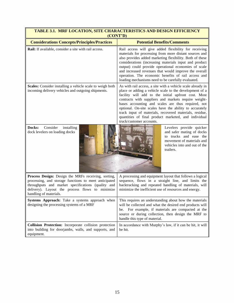
Docks: Consider installing
dock levelers on loading docks
Levelers provide quicker
and safer mating of docks
to trucks and ease the
movement of materials and
vehicles into and out of the
trailers.
Process Design: Design the MRFs receiving, sorting,
processing, and storage functions to meet anticipated
throughputs and market specifications (quality and
delivery). Layout the process flows to minimize
handling of materials.
A processing and equipment layout that follows a logical
sequence, flows in a straight line, and limits the
backtracking and repeated handling of materials, will
minimize the inefficient use of resources and energy.
Systems Approach: Take a systems approach when
designing the processing systems of a MRF
This requires an understanding about how the materials
will be collected and what the desired end products will
be. For example, if materials are compacted at the
source or during collection, then design the MRF to
handle this type of material.
Collision Protection: Incorporate collision protection
into building for doorjambs, walls, and supports, and
equipment.
In accordance with Murphy‘s law, if it can be hit, it will
be hit.
16
TABLE 3.1. MRF LOCATION, SITE CHARACTERISTICS AND DESIGN EFFICIENCY
(CONT’D)
Considerations Concepts/Principles/Practices Potential Benefits/Comments
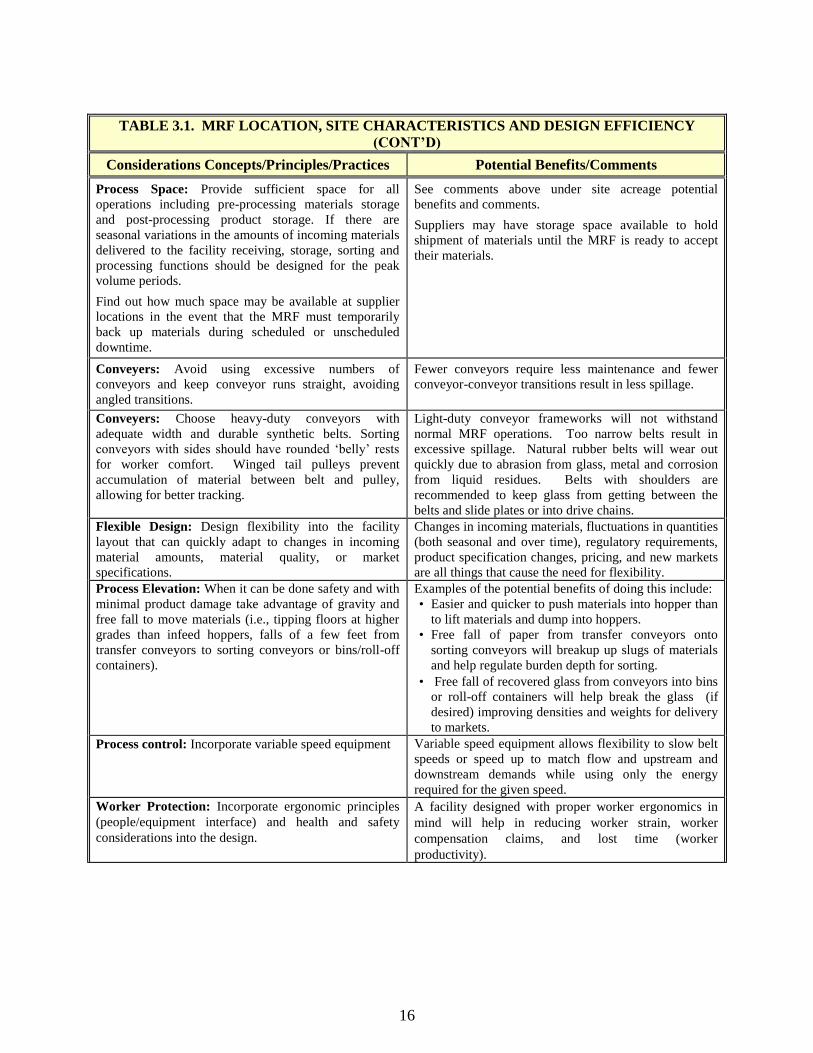
Process Space: Provide sufficient space for all
operations including pre-processing materials storage
and post-processing product storage. If there are
seasonal variations in the amounts of incoming materials
delivered to the facility receiving, storage, sorting and
processing functions should be designed for the peak
volume periods.
Find out how much space may be available at supplier
locations in the event that the MRF must temporarily
back up materials during scheduled or unscheduled
downtime.
See comments above under site acreage potential
benefits and comments.
Suppliers may have storage space available to hold
shipment of materials until the MRF is ready to accept
their materials.
Conveyers: Avoid using excessive numbers of
conveyors and keep conveyor runs straight, avoiding
angled transitions.
Fewer conveyors require less maintenance and fewer
conveyor-conveyor transitions result in less spillage.
Conveyers: Choose heavy-duty conveyors with
adequate width and durable synthetic belts. Sorting
conveyors with sides should have rounded ‗belly‘ rests
for worker comfort. Winged tail pulleys prevent
accumulation of material between belt and pulley,
allowing for better tracking.
Light-duty conveyor frameworks will not withstand
normal MRF operations. Too narrow belts result in
excessive spillage. Natural rubber belts will wear out
quickly due to abrasion from glass, metal and corrosion
from liquid residues. Belts with shoulders are
recommended to keep glass from getting between the
belts and slide plates or into drive chains.
Flexible Design: Design flexibility into the facility
layout that can quickly adapt to changes in incoming
material amounts, material quality, or market
specifications.
Changes in incoming materials, fluctuations in quantities
(both seasonal and over time), regulatory requirements,
product specification changes, pricing, and new markets
are all things that cause the need for flexibility.
Process Elevation: When it can be done safety and with
minimal product damage take advantage of gravity and
free fall to move materials (i.e., tipping floors at higher
grades than infeed hoppers, falls of a few feet from
transfer conveyors to sorting conveyors or bins/roll-off
containers).
Examples of the potential benefits of doing this include:
• Easier and quicker to push materials into hopper than
to lift materials and dump into hoppers.
• Free fall of paper from transfer conveyors onto
sorting conveyors will breakup up slugs of materials
and help regulate burden depth for sorting.
• Free fall of recovered glass from conveyors into bins
or roll-off containers will help break the glass (if
desired) improving densities and weights for delivery
to markets.
Process control: Incorporate variable speed equipment Variable speed equipment allows flexibility to slow belt
speeds or speed up to match flow and upstream and
downstream demands while using only the energy
required for the given speed.
Worker Protection: Incorporate ergonomic principles
(people/equipment interface) and health and safety
considerations into the design.
A facility designed with proper worker ergonomics in
mind will help in reducing worker strain, worker
compensation claims, and lost time (worker
productivity).

17
TABLE 3.1. MRF LOCATION, SITE CHARACTERISTICS AND DESIGN EFFICIENCY
(CONT’D)
Considerations Concepts/Principles/Practices Potential Benefits/Comments
Energy Use: Incorporate energy conservation principles
into the design, layout and equipment specifications for the
MRF. This includes building and site considerations such as
building orientation on site as well as procuring high-
quality, energy efficient equipment.
Over a 15, 20 or more years operating life, the cost of
energy in facility operations can be a significant cost.
It is likely that this will be even more so in the future.
Some of the concepts, principles and practices under
this category include:
• Utilize site geography and building placement to
minimize heat loss in winter by avoiding doors (or
minimizing their usage) on the north side of
buildings or in the direction of prevailing winds.
This is especially relevant if a drive through
concept is used for the tipping floor (design to
avoid wind tunnel effects).
• Utilize natural barriers (pine trees, hills, berms,
etc.) to protect facility from prevailing winds.
• If possible, enclose sorting areas (modular shells)
to minimize the amount of heat or air conditioning
needed to maintain a comfortable and safe
working environment for sorters.
• As an alternative to this last point, isolate areas
where doors leading to the outside environment
may be open much of the time (receiving areas
and shipping areas) from areas where workers are
sorting materials or operating other processing
equipment.
• Specify and purchase equipment that has a high-
energy efficiency rating. The capital cost may be
more but the long term operating costs should be
less.
• Purchase equipment that is properly sized for the
peak throughputs of materials. A higher rated
capacity baler will likely have a higher energy
efficiency rating, a quicker cycling time, and will
not be operating as much as a baler that is
undersized for the facility's throughput.
• Take advantage of natural daylighting. Design or
choose buildings with skylights and windows.
• Ensure materials being baled are of a consistent
quality and have little or no contamination, and
use baling wire strong enough to hold the bales
together for whatever material is being baled. This
will reduce the amount of material that needs to be
re-baled. An added benefit is the improved
marketability of the finished product.
This and following tables edited and adapted from: ―Materials Recovery Facilities Operational Assessment Final Report and Optimization
Guide”, Minnesota Office of Environmental Assistance, St. Paul, MN, August, 2003.

18
Many small to medium size MRFs utilize retrofitted existing structures. Finding an
existing facility that fits all the desirable criteria is difficult, however, the capital cost could be
substantially less than a ―greenfield‖ facility. Site-specific analyses are required to determine
costs of new versus retrofit costs.
If an existing building is used to house the MRF, items to consider include:
• Building shell type. Pre-engineered steel buildings are desirable as apposed to
wood frame. Typical types of former building uses suitable for conversion into a
MRF include warehouses and distribution centers, maintenance shops, and light
industrial manufacturing facilities.
• Clear span buildings are preferred for flexibility. Equipment, conveyors, storage
etc. can be more easily repositioned for operational flexibility and there are no
support pillars for vehicles to run into.
• Eave heights should be a minimum of 25 feet to accommodate the tipping of roll-
of containers and other self-dumping vehicles.
• Overhead doors providing access and egress to the facility should be of sufficient
height and width to accommodate the types of vehicles and equipment anticipated
to use them.
• Sufficient loading dock space should be available to accommodate delivery of
supplies as well as the staging/loading of several tractor-trailers. Four to six
loading docks are ideal.
• HVAC, lighting, and electrical service adequate for the building and equipment
used.
• Adequate space within the building should be available to incorporate a process
layout/materials flow that is logical, efficient, minimizes backtracking or multiple
handling of materials, and accommodates all operations efficiently and safely.
3.2 MATERIALS RECEIVING AND STAGING
The materials receiving and staging area
(tipping floor) design, layout and operations are
dependent on the type and quantity of materials
received at the facility and how those materials are
delivered to the facility.
The receiving and staging area for a MRF
may include as few as one tipping area for mixed
fibers and rigid containers (single-stream collection
and delivery), two separate tipping areas on the
tipping floor – one for fibers and one for rigid
containers (dual-stream collection and delivery), or
up to five or more separate tipping areas/bunkers for various combinations of commingled or
source separated collection and delivery.
19
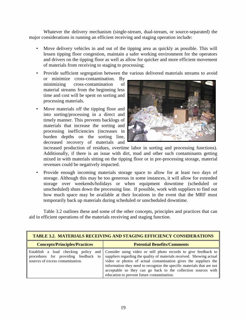
Whatever the delivery mechanism (single-stream, dual-stream, or source-separated) the
major considerations in running an efficient receiving and staging operation include:
• Move delivery vehicles in and out of the tipping area as quickly as possible. This will
lessen tipping floor congestion, maintain a safer working environment for the operators
and drivers on the tipping floor as well as allow for quicker and more efficient movement
of materials from receiving to staging to processing;
• Provide sufficient segregation between the various delivered materials streams to avoid
or minimize cross-contamination. By
minimizing cross-contamination of
material streams from the beginning less
time and cost will be spent on sorting and
processing materials.
• Move materials off the tipping floor and
into sorting/processing in a direct and
timely manner. This prevents backlogs of
materials that increase the sorting and
processing inefficiencies (increases in
burden depths on the sorting line,
decreased recovery of materials and
increased production of residues, overtime labor in sorting and processing functions).
Additionally, if there is an issue with dirt, mud and other such contaminants getting
mixed in with materials sitting on the tipping floor or in pre-processing storage, material
revenues could be negatively impacted.
• Provide enough incoming materials storage space to allow for at least two days of
storage. Although this may be too generous in some instances, it will allow for extended
storage over weekends/holidays or when equipment downtime (scheduled or
unscheduled) shuts down the processing line. If possible, work with suppliers to find out
how much space may be available at their locations in the event that the MRF must
temporarily back up materials during scheduled or unscheduled downtime.
Table 3.2 outlines these and some of the other concepts, principles and practices that can
aid in efficient operations of the materials receiving and staging function.
TABLE 3.2. MATERIALS RECEIVING AND STAGING EFFICIENCY CONSIDERATIONS
Concepts/Principles/Practices Potential Benefits/Comments
Establish a load checking policy and
procedures for providing feedback to
sources of excess contamination.
Consider using video or still photo records to give feedback to
suppliers regarding the quality of materials received. Showing actual
video or photos of actual contamination gives the suppliers the
information they need to recognize the specific materials that are not
acceptable so they can go back to the collection sources with
education to prevent future contamination.
20
TABLE 3.2: MATERIALS RECEIVING AND STAGING EFFICIENCY CONSIDERATIONS
(CONT’D)
Concepts/Principles/Practices Potential Benefits/Comments
Move materials off the tipping floor and to
sorting/processing in a timely and consistent manner.
Aim for processing all materials the same day they are
received.
Storing materials means double handling, reducing
efficiencies. Slugs of material often lead to inefficient
sorting, and times when workers are waiting for
materials. Processing efficiencies in both manual and
mechanical sorting will be improved with consistent
material flows, resulting in fewer residues generated.
Provide for two days of incoming materials storage at
peak flows. This storage can be on-site or possibly at
supplier sites.
Allows for storage over extended weekends or when
processing is halted due to equipment repair or
maintenance.
Provide for segregation of incoming materials by the
use of material bunkers or specified areas where certain
types of materials are dumped.
Minimizes cross-contamination of materials making it
easier to sort by material types and grades (i.e., metal
food and beverage containers, plastic containers, OCC,
other fibers, etc.)
If necessary, contain separation of incoming materials
at peak flows by using portable traffic barriers.
Potential benefits include:
• Minimizes interference with vehicles maneuvering
around the tipping floor and unloading their contents.
• Minimizes cross-contamination of incoming materials,
which could add to the time and effort involved in
sorting operations.
Provide for safe, quick and easy traffic control to move
vehicles on to and off of the tipping floor. This could
include a one-way drive through concept with traffic
entering through one door and exiting through another.
A good traffic flow and control plan will keep vehicles
and materials moving in a safe and efficient manner. If
considering the one-way drive through concept, take into
account such things as the potential for wind tunnel
effects and the ability of vehicles to maneuver on the
tipping floor.
If the facility will serve the general public as well as
commercial and public haulers, consider a separate
drop-off area for the public.
The benefit in doing this is to minimize congestion on the
tipping floor by designating it for larger volume
deliveries as well as to provide for a safe tipping area for
the general public.
Provide for safe, quick and easy unloading of vehicles
on the tipping floor.
The goal is to minimize the time vehicles are on the
tipping floor and to provide for an unloading plan that
will quickly and safely move materials from vehicle to
pre-processing storage.
Keep tipping floors and receiving areas away from
other facility functions such as materials sorting,
materials baling, and product storage.
When a variety of facility operational components share
the same space or are adjacent to each other without
sufficient barriers or buffer areas there is a loss of
efficiency due to operational congestion and potential
cross contamination. Additionally, with more cross traffic
and greater points of interface between vehicles,
equipment, and pedestrians, facility safety is
compromised.
Utilize gravity and free fall to move materials from
staging to processing.
The use of below-grade conveyor systems minimizes the
handling of materials and makes it easier to move
materials out to processing.

21
TABLE 3.2: MATERIALS RECEIVING AND STAGING EFFICIENCY CONSIDERATIONS
(CONT’D)
Concepts/Principles/Practices Potential Benefits/Comments
If utilizing gravity and free fall to move materials from
staging to processing, take steps to minimize glass
breakage if glass is to be color sorted.
Minimizing glass breakage will result in safer, more
efficient sorting operations, increase glass recovery, and
decrease residue amounts requiring disposal. Ways to do
this include:
• If sorting mixed containers, collect and dump glass
along with plastics to help cushion the glass during
dumping.
• Adding deflection ramps and rubber baffles at impact
points.
• Utilizing drop chutes that reduce drop distances and
encourage glass containers to roll rather than break.
3.3 MATERIALS SORTING CONSIDERATIONS
The sorting of materials at a MRF is the heart of the MRF. Whether the sorting process
is accomplished manually, mechanically, or a combination of the two, it is usually the
operational component of the MRF that is the largest cost center and offers the greatest potential
for both short-term and long-term savings. These savings include increased revenue for higher
quality material, cost savings from reduced residue disposal costs and decreased labor costs. The
sorting process is also the component where quality control becomes an important consideration.
The following subsections provide ideas into improving efficiencies in both manual and
mechanical sorting functions. Smaller MRFs, many of which are located in rural or small town
areas, typically rely mainly on manual sorting techniques. Though there are opportunities in
these types of operations to add equipment that will improve overall sorting efficiencies and
offer long-term savings, due to the lower throughput of materials at small MRFs, the application
of mechanical sorting techniques is limited and cost prohibitive for some facilities. As the
throughput of a MRF increases, adding mechanical sorting equipment becomes more cost-
effective. When designing a new MRF, plan for increased material rates and oversize
equipment by some % of what you expect to receive to accommodate market changes and new
suppliers .

22
3.3.1 MANUAL SORTING OF MATERIALS
Improving the efficiencies of manual sorting is more than just proper training of the
workforce and providing a safe and comfortable work environment for the sorters. It also
involves providing the right equipment and procedures to make the sorting process more
effective. Productivity levels can be significantly enhanced with the right combination of
personnel training, procedures, and equipment.
Some of the factors that will contribute to increased efficiencies in manual sorting
include such items as:
• Design and operation of conveyance systems;
• Control of the burden depth and uniformity of the materials crossing the sorting belt;
• Sorter experience and training;
• The level of mechanical sorting supplementing manual sorting; and
• Policies, procedures, and practices employed in the sorting operation.
The concepts, principles and practices that can impact the efficiencies and effectiveness of
manual sorting are listed in Table 3.3.1. It should be noted that the extent to which these ideas
can be applied to a specific operation is dependent on local factors such as the types of materials
collected and delivered, the method of collection and delivery, the design and layout of the MRF,
23
the level of manual sorting versus mechanical sorting, and the level of processing required to
meet market specifications.
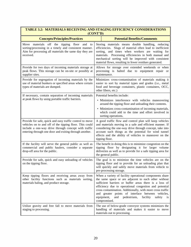
TABLE 3.3.1. MANUAL SORTING EFFICIENCY CONSIDERATIONS
Concepts/Principles/Practices Potential Benefits/Comments
Provide appropriate training and instruction to sorters. Training materials should include pictures and words in
English, Spanish or other native languages as necessary
describing targeted recyclables and prohibitives. Have
posters showing the flow of materials through the plant
and pictures of targeted materials in the appropriate
sorting stalls. For new or temporary workers provide
immediate feedback in the first 2-3 hours of work.
Provide an environmentally comfortable and safe
working environment. This includes:
• Space that is heated in the winter, cooled in the
summer, and has good air exchange (ventilation).
• Anti-fatigue mats to reduce the physical discomfort
of standing in one place for long periods of time.
• Sufficient lighting to reduce eyestrain.
• Gloves, safety glasses, hearing protection, steel-toed
boots, and, if applicable, hardhats and facemasks.
Potential benefits include increased productivity as
tiredness and strain are reduced, and overall physical
comfort is maintained or increased. Additionally, the use
of personal protective equipment (PPE) reduces the risk
of injury, which in turn reduces the potential of worker
compensation claims, lost time on the job, and increased
insurance rates.
Sorting conveyors should be less than 36‖ wide if
sorting from one side of the conveyor.
Being able to comfortably reach across the width of the
conveyor to remove items will increase the amount of
materials recovered while reducing ―missed items‖ that
end up in the residue stream. If sorting from one side of
the conveyor a 36‖ stretch is about the furthest one can
reach without causing undo physical strain. If sorters are
working both sides of the conveyor belt widths of up to
60‖ are acceptable. Wider belts can be acceptable if
sorting large materials such as OCC.
Sorting stations and conveyors should be ergonomically
designed and worker friendly. For example: Conveyor
belts should be between 36"and 42" in height as
measured from the floor to top of belt.
Conveyor belts below 36" in height may put excessive
back strain on sorters. Belts greater than 42" in height
will limit the extent to which an average person can lean
over while reaching for an object, thus causing strain
while stretching to sort materials. Proper surface height
for an average worker sorting large materials such as
OCC should be 36‖-38‖. Sorting of smaller items
should be done at a height of 40‖-42‖. Make safe risers
available to sorters below average height or they may
improvise unsafe platforms to reach a comfortable
position.
While at a presort conveyor a vertical sidewall extension
is recommended to protect sorters from moving
conveyor belt and provide a barrier so that materials
don't falloff, the trend for newer sorting conveyors is a
troughed design without sides to reduce lifting motion
for sorters. Both cases should provide a rounded ―belly
rest‖ edge.
Workers will come into contact with the sidewall
extension during the course of the sorting operation.
This contact (between hips and waist) can cause a
physical strain on the body. Rubber or foam padding
will minimize the strain.
24
TABLE 3.3.1. MANUAL SORTING EFFICIENCY CONSIDERATIONS (CONT’D)
Concepts/Principles/Practices Potential Benefits/Comments
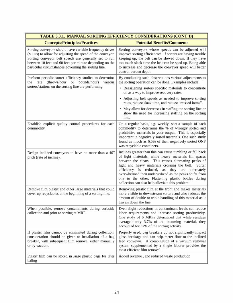
Sorting conveyors should have variable frequency drives
(VFDs) to allow for adjusting the speed of the conveyor.
Sorting conveyor belt speeds are generally set to run
between 10 feet and 60 feet per minute depending on the
particular circumstances governing the sorting line.
Sorting conveyors whose speeds can be adjusted will
improve sorting efficiencies. If sorters are having trouble
keeping up, the belt can be slowed down. If they have
too much slack time the belt can be sped up. Being able
to increase and decrease the conveyor speed will better
control burden depth.
Perform periodic sorter efficiency studies to determine
the rate (throws/hour or pounds/hour) various
sorters/stations on the sorting line are performing.
By conducting such observations various adjustments to
the sorting operation can be done. Examples include:
• Reassigning sorters specific materials to concentrate
on as a way to improve recovery rates.
• Adjusting belt speeds as needed to improve sorting
rates, reduce slack time, and reduce ―missed items‖.
• May allow for decreases in staffing the sorting line or
show the need for increasing staffing on the sorting
line.
Establish explicit quality control procedures for each
commodity
On a regular basis, e.g. weekly, sort a sample of each
commodity to determine the % of wrongly sorted and
prohibitive materials in your output. This is especially
important in negatively sorted materials. One such study
found as much as 6.5% of their negatively sorted ONP
was recyclable containers.
Design inclined conveyors to have no more than a 40º pitch (rate of incline).
Inclines greater than this can cause tumbling or fall back
of light materials, while heavy materials fill spaces
between the cleats. This causes alternating peaks of
light and heavy materials crossing the belt. Sorter
efficiency is reduced, as they are alternately
overwhelmed then underutilized as the peaks shifts from
one to the other. Flattening plastic bottles during
collection can also help alleviate this problem.
Remove film plastic and other large materials that could
cover up recyclables at the beginning of a sorting line.
Removing plastic film at the front end makes materials
more visible to downstream sorters and also reduces the
amount of double or triple handling of this material as it
travels down the line.
When possible, remove contaminants during curbside
collection and prior to sorting at MRF.
Even slight reductions in contaminant levels can reduce
labor requirements and increase sorting productivity.
One study of 6 MRFs determined that while residues
averaged only 3.7% of the incoming material, they
accounted for 37% of the sorting activity.
If plastic film cannot be eliminated during collection,
consideration should be given to installation of a bag
breaker, with subsequent film removal either manually
or by vacuum.
Properly used, bag breakers do not significantly impact
glass breakage and can help meter flow to the inclined
feed conveyor. A combination of a vacuum removal
system supplemented by a single laborer provides the
most efficient film removal.
Plastic film can be stored in large plastic bags for later
baling
Added revenue , and reduced waste production

25
TABLE 3.3.1. MANUAL SORTING EFFICIENCY CONSIDERATIONS (CONT’D)
Concepts/Principles/Practices Potential Benefits/Comments
Control burden depth of materials crossing the sorting
belt. The burden depth of fibers, as an example, should
be less than 12‖ deep. A variety of methods can be used
to control burden depth and the amount of materials
presented to sorters for sorting. These include such
things as:
• Slow down or speed up the rate at which materials
are fed into hoppers or onto inclined conveyors.
• On fiber lines allow for a drop from one conveyor to
the next of two to three feet. This helps break up
clumps of materials.
• Adjust speed of conveyor belts to either increase the
amount of materials presented to a sorter or
decrease the amount of materials presented to a
sorter. To decrease burden depth, a sorting conveyor
should run at a higher speed than the conveyor
feeding it.
• Utilize other physical or mechanical means such as
hanging chains or rotating cleated drums to help
knockdown or breakup large slugs of materials
traveling up the feed conveyor.
Problems with controlling burden depth have been an
issue in several MRF studies. Without adequate controls
for monitoring and adjusting burden depth a variety of
efficiency issues can occur including:
• Overwhelming workers to the point where they need
to push materials back up the line or stop the line
altogether in order to catch up.
• Decreasing the amount of recoverable materials
captured while increasing the amount of process
residue requiring disposal.
• Allowing contaminant levels to increase in recovered
products resulting in lower revenues for recovered
products or rejection of recovered products.
• Resorting of materials in order to capture more
product or clean product up.
• Periods of very low levels of materials passing by
sorters, which have them sorting at very low rates, or
not sorting at all, due to the lack of anything on the
sorting belt (sometimes referred to as ―black belt‖).
Items to the left are all methods that have been
employed to adjust burden depths and equalize the flow
of materials across the sorting belt. Implementing these
methods help achieve peak efficiencies in the sorting
operation.
On a mixed fibers line (excluding OCC) negative sort
the highest volume of materials (usually ONP or a mixed
paper grade).
With fibers especially, allowing the highest volume of
material to flow off the end as a negative sort will
minimize the amount and effort of trying to sort this
material. Sorting efficiencies will be improved.
Sorters should be throwing forward into a
bunker/bin/gaylord and not pulling materials back off
the belt.
Sorters that must twist or reach behind them to deposit
materials in a chute or bin are subject to more strain and
tire quicker. In addition to being more ergonomically
correct, one study that compared sorting rates
determined that a sorter throwing forward could
maintain a sorting rate up to three times the sorter
pulling the material back.
Install backsplashes on openings to chutes or bins. The
top of the chutes should be level or below height of
sorting belt so sorters do not need to lift material any
higher than necessary
Less time is wasted in retrieving mis-thrown materials
from the wrong bin or from the floor and sorters can
move faster if less time is spent targeting the opening.
Assign sorters specific items to sort, rather than
assigning all sorters on a line to sort all materials.
Sorting efficiencies and recovery rates will improve if
sorters have fewer materials they have to concentrate on
sorting. Additionally, fewer bins or gaylords will be
required thus easing congestion and improving overall
operation of the sorting line.
Remove broken glass before sorting line. A screen or trommel to remove broken glass can
improve sorting efficiency, by allowing sorters to move
rapidly without as much danger of being cut.

26
TABLE 3.3.1. MANUAL SORTING EFFICIENCY CONSIDERATIONS (CONT’D)
Concepts/Principles/Practices Potential Benefits/Comments
Discontinue activities on the sorting line that provide
little to no value and aren‘t directly related to materials
sorting (e.g., removing caps from plastic bottles).
Sorting rates will be improved and the amount of
materials recovered may increase if less time is spent on
―no value added‖ activities such as this. In this example,
if the goal of removing the plastic caps is to prevent
trapped air from reducing baling densities, purchasing a
plastics perforator and perforating the plastics prior to
baling will likely be more cost effective in the long-term.
If quantities of some recovered materials are very low
(even with relatively high prices), the economics of
sorting these materials should be reviewed and
consideration given to continuing sorting these items.
The incremental cost of recovering smaller volumes of
some recyclable materials is negligible. It is always
better to recover the materials for recycling than to throw
recyclable materials away. For example, aseptic
packaging may represent a small percentage of recyclable
materials compared to other recyclable commodities;
however, the cost to recover these materials is small since
most MRFs are already presenting these materials on a
conveyor sorting line where the material can be easily
picked along with other commodities. However, the cost
of sorting, preparing, storing and marketing a material
needs to be balanced with the additional revenues
received for recovery or upgrading of that material. If the
quantities received are too small, it may be more cost
effective to handle some marketable materials as residues.
A joint American/Canadian Study of MRF operations (See references 4. and 10.) established
benchmark manual sorting rates. These benchmarks were defined as the highest, continuously
sustainable sorting rate by a single sorter under optimum conditions. It should be noted that the
highest rates for plastic were seen where air classifiers were used to separate ―lights‖ from
―heavies.
Since the study, performed in 2000, several changes have led to lower sorting rates for plastics.
Bottle manufacturers are now using less material per bottle, and also there are more single
serving containers thus reducing the net sorting rate in pounds per hour. Single serving PET
water bottles are now manufactured using 16 to 18 grams of resin as compared to 25 grams just a
couple of years ago.
Given that no other rate study has been conducted, Table 3.3.2 below, includes our estimate of
current sorting rates in addition to the Study benchmark rates.
TABLE 3.3.2. MANUAL SORTING BENCHMARK SORTING RATES
Material Benchmark (lbs/hr/sorter) Adjusted (lbs/hr/sorter)
HDPE (natural) 990 (lbs/hr/sorter) 300-500 (lbs/hr/sorter)
HDPE (colored) 925 (lbs/hr/sorter) 300-600 (lbs/hr/sorter)
HDPE (mixed) 990 (lbs/hr/sorter) 300-550 (lbs/hr/sorter)
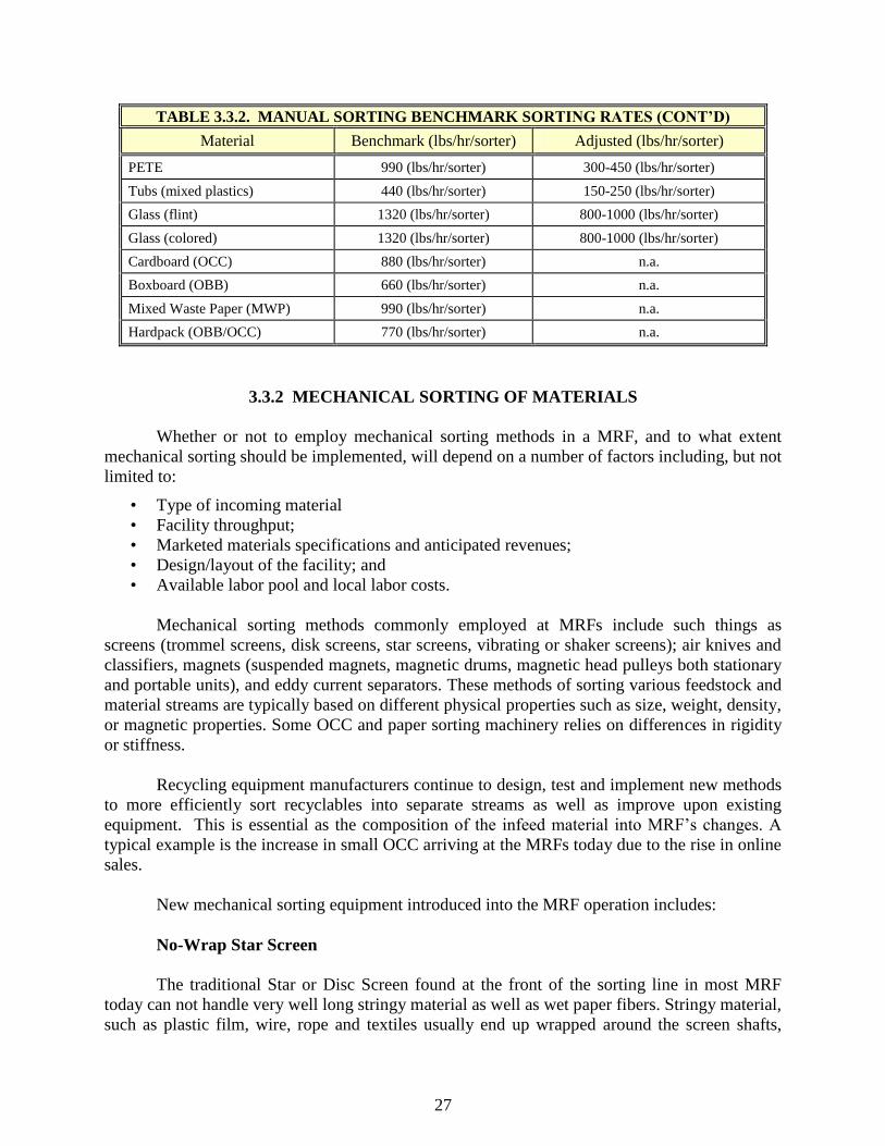
27
TABLE 3.3.2. MANUAL SORTING BENCHMARK SORTING RATES (CONT’D)
Material Benchmark (lbs/hr/sorter) Adjusted (lbs/hr/sorter)
PETE 990 (lbs/hr/sorter) 300-450 (lbs/hr/sorter)
Tubs (mixed plastics) 440 (lbs/hr/sorter) 150-250 (lbs/hr/sorter)
Glass (flint) 1320 (lbs/hr/sorter) 800-1000 (lbs/hr/sorter)
Glass (colored) 1320 (lbs/hr/sorter) 800-1000 (lbs/hr/sorter)
Cardboard (OCC) 880 (lbs/hr/sorter) n.a.
Boxboard (OBB) 660 (lbs/hr/sorter) n.a.
Mixed Waste Paper (MWP) 990 (lbs/hr/sorter) n.a.
Hardpack (OBB/OCC) 770 (lbs/hr/sorter) n.a.
3.3.2 MECHANICAL SORTING OF MATERIALS
Whether or not to employ mechanical sorting methods in a MRF, and to what extent
mechanical sorting should be implemented, will depend on a number of factors including, but not
limited to:
• Type of incoming material
• Facility throughput;
• Marketed materials specifications and anticipated revenues;
• Design/layout of the facility; and
• Available labor pool and local labor costs.
Mechanical sorting methods commonly employed at MRFs include such things as
screens (trommel screens, disk screens, star screens, vibrating or shaker screens); air knives and
classifiers, magnets (suspended magnets, magnetic drums, magnetic head pulleys both stationary
and portable units), and eddy current separators. These methods of sorting various feedstock and
material streams are typically based on different physical properties such as size, weight, density,
or magnetic properties. Some OCC and paper sorting machinery relies on differences in rigidity
or stiffness.
Recycling equipment manufacturers continue to design, test and implement new methods
to more efficiently sort recyclables into separate streams as well as improve upon existing
equipment. This is essential as the composition of the infeed material into MRF‘s changes. A
typical example is the increase in small OCC arriving at the MRFs today due to the rise in online
sales.
New mechanical sorting equipment introduced into the MRF operation includes:
No-Wrap Star Screen
The traditional Star or Disc Screen found at the front of the sorting line in most MRF
today can not handle very well long stringy material as well as wet paper fibers. Stringy material,
such as plastic film, wire, rope and textiles usually end up wrapped around the screen shafts,

28
creating reduced sorting efficiency and downtime for maintenance.
A No-Wrap star screen has been designed, tested and patented, by a leading equipment
manufacturer that greatly reduces the problem of associated with stringy material being wrapped
on the screen.
Ballistic Separator
Ballistic separators which were originally designed for MSW have been modified and are
being incorporated into MRF‘s
The basic principle of the Ballistic Separator is based upon 6 rotating paddles arranged
parallel to each other, with dual transmission.
Each set of paddles is constructed with the
possibility of angle adjustments, which allows
the separator to adapt to the input material.
Depending on application the paddle surfaces are
designed with perforations to screen out smaller
materials.
The ballistic separator allows the
classification of one input material stream into
two or more fractions. In comparison with
traditional screener specialized on the separation
of materials by size, the ballistic separator
manages to combine classification in size and form.
The single-stage core machine is
separating one material stream
into two main fractions, as there
are:
―rolling heavy fraction‖ (wood,
tins, selected steel, massive
plastic parts etc.) and ―flat light
fraction‖ (foils, textile, paper,
cardboard).
. This equipment effectively
screens fiber from containers
while also removing fines from
the material stream. As with
disc screens, by changing the
screen size, different fractions
can be easily removed.

29
Bouncing Belt
Another sorting machine with a similar principle to the ballistic separator consists of a
conveyor belt fitted with shafts with cams that ‗bounce‘ the belt as it travels. This action allows
the flat material to travel up the belt while the three dimensional containers fall off the bottom of
the belt.
Drum Air Classifiers
MRF‘s have used air classifiers to sort materials by density. Original models were
limited in their flexibility to accommodate to changing material stream composition. Basically
changes were limited to air flow and material settings.
A Drum Air Classifier developed to effectively remove ONP from mixed paper and rigid
containers offers greater flexibility to process different feedstock composition.
The infeed conveyor belt speed, incline angle and proximity to the air chamber can easily be
adjusted. The internal drum speed is adjustable as well as the air flow quantity and shape of air
stream.
Polishing Equipment
An additional class of sorting equipment, designated broadly as Polishing Equipment, has been
developed to improve the quality of single material streams produced at the MRF.

30
Paper Spike
In order to provide a less contaminated
ONP bale, the Paper Spike removes all
remaining OCC from News, Mixed Paper and
magazines.
The principle is simple and effective. The
material is fed in a single layer into the Paper
Spike. The belt spikes then pierce the Paper and Cardboard. Due to the various properties of
rigidity, paper immediately drop off the spikes, whereas cardboard stick onto the spikes and is
transported to the end of the line, where they are removed and sent to a separate bin. .
Paper Vacuum Magnet
The Paper Magnet is designed to separate paper from containers. The machine consists of
a perforated belt with vacuum applied to its underside. Fiber sticks to the belt and is carried up
and over the head pulley, while containers tumble down the back of the conveyor.
Film Grabber
The implementation of Single-Stream processing has resulted in an increase of plastics
film delivered to the MRF, since the commingled recyclable materials are stored in plastics bags
by the homeowners prior to set them a the curbside for collection.
The bags are opened at the MRF by a bag breaker, however the plastic film creates a
problem for the subsequent sorting operation, requiring additional labor to hand remove it from
the commingled feedstock.
The patented film grabber, consists of a revolving drum with movable spikes. The flow of
recyclable materials is led uniformly to the film grabber by a conveyor belt. The spikes of the
film grabber grab the film from the material flow and delivers it to a separate bin. The rest of the
material flow drops under the film grabber onto another belt. This equipment is currently in use
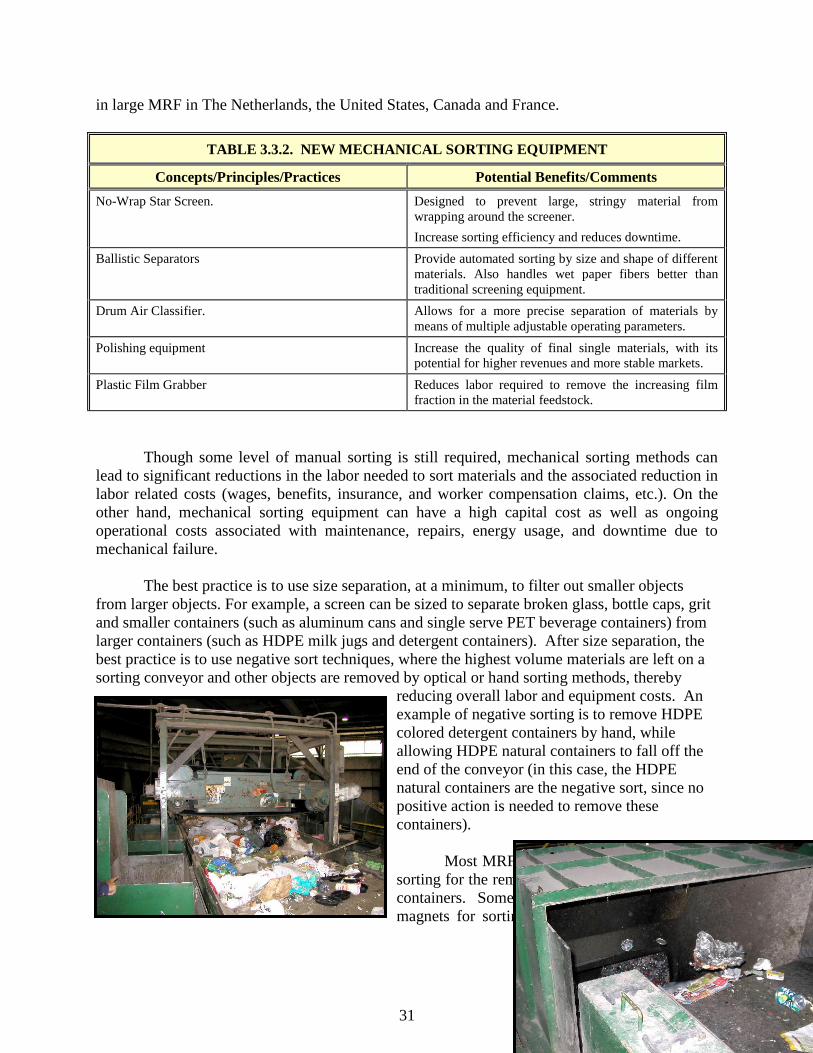
31
in large MRF in The Netherlands, the United States, Canada and France.
TABLE 3.3.2. NEW MECHANICAL SORTING EQUIPMENT
Concepts/Principles/Practices Potential Benefits/Comments
No-Wrap Star Screen. Designed to prevent large, stringy material from
wrapping around the screener.
Increase sorting efficiency and reduces downtime.
Ballistic Separators Provide automated sorting by size and shape of different
materials. Also handles wet paper fibers better than
traditional screening equipment.
Drum Air Classifier. Allows for a more precise separation of materials by
means of multiple adjustable operating parameters.
Polishing equipment Increase the quality of final single materials, with its
potential for higher revenues and more stable markets.
Plastic Film Grabber Reduces labor required to remove the increasing film
fraction in the material feedstock.
Though some level of manual sorting is still required, mechanical sorting methods can
lead to significant reductions in the labor needed to sort materials and the associated reduction in
labor related costs (wages, benefits, insurance, and worker compensation claims, etc.). On the
other hand, mechanical sorting equipment can have a high capital cost as well as ongoing
operational costs associated with maintenance, repairs, energy usage, and downtime due to
mechanical failure.
The best practice is to use size separation, at a minimum, to filter out smaller objects
from larger objects. For example, a screen can be sized to separate broken glass, bottle caps, grit
and smaller containers (such as aluminum cans and single serve PET beverage containers) from
larger containers (such as HDPE milk jugs and detergent containers). After size separation, the
best practice is to use negative sort techniques, where the highest volume materials are left on a
sorting conveyor and other objects are removed by optical or hand sorting methods, thereby
reducing overall labor and equipment costs. An
example of negative sorting is to remove HDPE
colored detergent containers by hand, while
allowing HDPE natural containers to fall off the
end of the conveyor (in this case, the HDPE
natural containers are the negative sort, since no
positive action is needed to remove these
containers).
Most MRFs use some form of mechanical
sorting for the removal and or separation of metal
containers. Some use self-cleaning suspended
magnets for sorting ferrous directly off the line

32
while others use portable magnetic head pulleys as a supplement to hand sorting of ferrous and
aluminum. In this latter case the facilities run the hand-sorted aluminum fraction through
portable units to remove any ferrous containers that may have been mis-sorted. Because the
payback for utilizing an eddy current separator is not very long, many smaller MRF‘s have
incorporated eddy currents into their line. Savings is also seen in the aluminum quality as well.
Some of the things to consider when looking at the use of mechanical methods for the sorting of
metals are summarized in Table 3.3.2
TABLE 3.3.3. MECHANICAL SORTING OF METALS EFFICIENCY CONSIDERATIONS
Concepts/Principles/Practices Potential Benefits/Comments
When using a self-cleaning suspended magnet to pull
ferrous metals from mixed containers flowing across a
sorting belt, remove large items (plastic film, bagged
materials, bulky HDPE plastic containers) prior to the
magnet.
This will prevent larger materials from jamming the
conveyor under the magnet‘s head, expose more metal
for recovery by the suspended magnet, and increase the
ferrous recovery rate.
Take extra care to remove plastic film bags before
magnetic or eddy current separation.
Entangled film can prevent separation of materials and
drag unwanted contamination along with separated
materials. Film also wraps around rotating machine
parts.
The ideal installation of a suspended magnet is over the
trajectory of material discharged from a conveyor belt.
In this position the material is moving directly toward
the magnetic face and its momentum increases the
recovery of the ferrous.
This assumes a rapid belt speed. As the belt speed
decreases the trajectory of the material becomes more
nearly vertical. This requires the repositioning of the
magnet back over the head pulley in a vertical position.
Providing a clearance height of 12 inches to 15 inches
from magnet head to top of belt should allow nonferrous
items such as aluminum, glass and residue to pass under
the unit without interfering with the recovery of ferrous
containers.
The pulling strength of many suspended magnets can be
adjusted to compensate for various clearance heights.
Doing so will allow for the effective recovery of ferrous
containers passing under the magnet. The frame of the
sorting conveyor beneath the magnet should be made of
non-magnetic material to prevent magnetization of the
frame.
When using a suspended magnet, the effective magnetic
width of the device should provide full coverage of the
sorting belt.
If the effective magnetic width of the magnet doesn‘t
cover the entire width of the sorting belt, recovery rates
will be less.
TABLE 3.3.3. MECHANICAL SORTING OF METALS EFFICIENCY CONSIDERATIONS
(CONT’D)
Concepts/Principles/Practices Potential Benefits/Comments
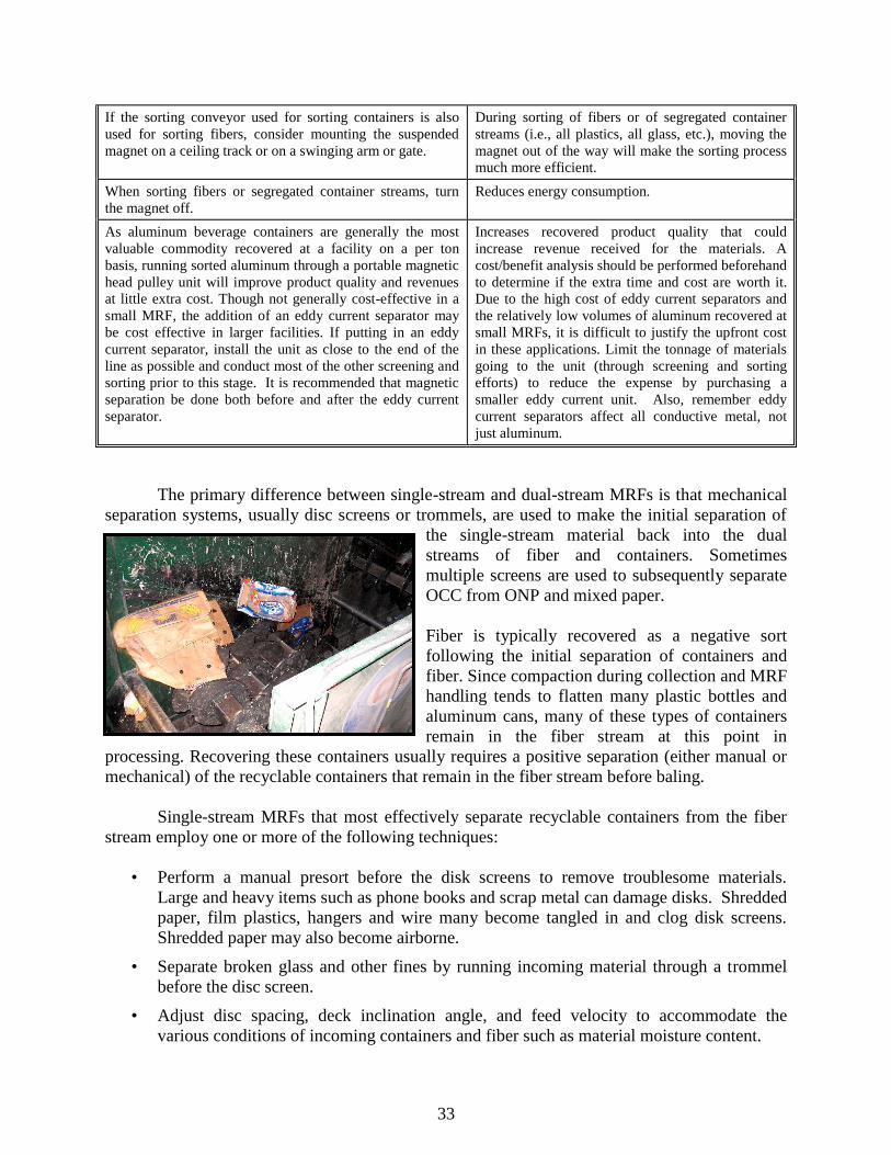
33
If the sorting conveyor used for sorting containers is also
used for sorting fibers, consider mounting the suspended
magnet on a ceiling track or on a swinging arm or gate.
During sorting of fibers or of segregated container
streams (i.e., all plastics, all glass, etc.), moving the
magnet out of the way will make the sorting process
much more efficient.
When sorting fibers or segregated container streams, turn
the magnet off.
Reduces energy consumption.
As aluminum beverage containers are generally the most
valuable commodity recovered at a facility on a per ton
basis, running sorted aluminum through a portable magnetic
head pulley unit will improve product quality and revenues
at little extra cost. Though not generally cost-effective in a
small MRF, the addition of an eddy current separator may
be cost effective in larger facilities. If putting in an eddy
current separator, install the unit as close to the end of the
line as possible and conduct most of the other screening and
sorting prior to this stage. It is recommended that magnetic
separation be done both before and after the eddy current
separator.
Increases recovered product quality that could
increase revenue received for the materials. A
cost/benefit analysis should be performed beforehand
to determine if the extra time and cost are worth it.
Due to the high cost of eddy current separators and
the relatively low volumes of aluminum recovered at
small MRFs, it is difficult to justify the upfront cost
in these applications. Limit the tonnage of materials
going to the unit (through screening and sorting
efforts) to reduce the expense by purchasing a
smaller eddy current unit. Also, remember eddy
current separators affect all conductive metal, not
just aluminum.
The primary difference between single-stream and dual-stream MRFs is that mechanical
separation systems, usually disc screens or trommels, are used to make the initial separation of
the single-stream material back into the dual
streams of fiber and containers. Sometimes
multiple screens are used to subsequently separate
OCC from ONP and mixed paper.
Fiber is typically recovered as a negative sort
following the initial separation of containers and
fiber. Since compaction during collection and MRF
handling tends to flatten many plastic bottles and
aluminum cans, many of these types of containers
remain in the fiber stream at this point in
processing. Recovering these containers usually requires a positive separation (either manual or
mechanical) of the recyclable containers that remain in the fiber stream before baling.
Single-stream MRFs that most effectively separate recyclable containers from the fiber
stream employ one or more of the following techniques:
• Perform a manual presort before the disk screens to remove troublesome materials.
Large and heavy items such as phone books and scrap metal can damage disks. Shredded
paper, film plastics, hangers and wire many become tangled in and clog disk screens.
Shredded paper may also become airborne.
• Separate broken glass and other fines by running incoming material through a trommel
before the disc screen.
• Adjust disc spacing, deck inclination angle, and feed velocity to accommodate the
various conditions of incoming containers and fiber such as material moisture content.
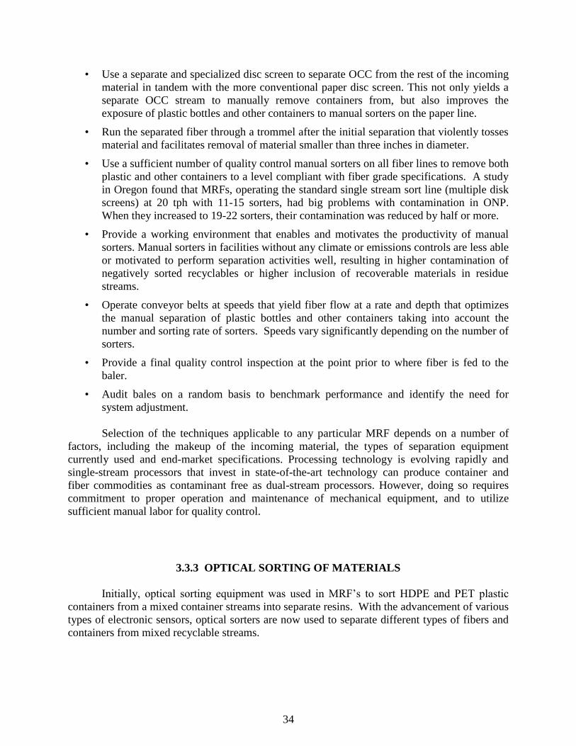
34
• Use a separate and specialized disc screen to separate OCC from the rest of the incoming
material in tandem with the more conventional paper disc screen. This not only yields a
separate OCC stream to manually remove containers from, but also improves the
exposure of plastic bottles and other containers to manual sorters on the paper line.
• Run the separated fiber through a trommel after the initial separation that violently tosses
material and facilitates removal of material smaller than three inches in diameter.
• Use a sufficient number of quality control manual sorters on all fiber lines to remove both
plastic and other containers to a level compliant with fiber grade specifications. A study
in Oregon found that MRFs, operating the standard single stream sort line (multiple disk
screens) at 20 tph with 11-15 sorters, had big problems with contamination in ONP.
When they increased to 19-22 sorters, their contamination was reduced by half or more.
• Provide a working environment that enables and motivates the productivity of manual
sorters. Manual sorters in facilities without any climate or emissions controls are less able
or motivated to perform separation activities well, resulting in higher contamination of
negatively sorted recyclables or higher inclusion of recoverable materials in residue
streams.
• Operate conveyor belts at speeds that yield fiber flow at a rate and depth that optimizes
the manual separation of plastic bottles and other containers taking into account the
number and sorting rate of sorters. Speeds vary significantly depending on the number of
sorters.
• Provide a final quality control inspection at the point prior to where fiber is fed to the
baler.
• Audit bales on a random basis to benchmark performance and identify the need for
system adjustment.
Selection of the techniques applicable to any particular MRF depends on a number of
factors, including the makeup of the incoming material, the types of separation equipment
currently used and end-market specifications. Processing technology is evolving rapidly and
single-stream processors that invest in state-of-the-art technology can produce container and
fiber commodities as contaminant free as dual-stream processors. However, doing so requires
commitment to proper operation and maintenance of mechanical equipment, and to utilize
sufficient manual labor for quality control.
3.3.3 OPTICAL SORTING OF MATERIALS
Initially, optical sorting equipment was used in MRF‘s to sort HDPE and PET plastic
containers from a mixed container streams into separate resins. With the advancement of various
types of electronic sensors, optical sorters are now used to separate different types of fibers and
containers from mixed recyclable streams.
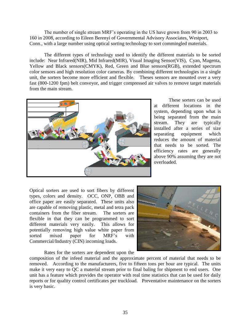
35
The number of single stream MRF‘s operating in the US have grown from 90 in 2003 to
160 in 2008, according to Eileen Berenyi of Governmental Advisory Associates, Westport,
Conn., with a large number using optical sorting technology to sort commingled materials.
The different types of technology used to identify the different materials to be sorted
include: Near Infrared(NIR), Mid Infrared(MIR), Visual Imaging Sensor(VIS), Cyan, Magenta,
Yellow and Black sensors(CMYK), Red, Green and Blue sensors(RGB), extended spectrum
color sensors and high resolution color cameras. By combining different technologies in a single
unit, the sorters become more efficient and flexible. Theses sensors are mounted over a very
fast (800-1200 fpm) belt conveyor, and trigger compressed air valves to remove target materials
from the main stream.
These sorters can be used
at different locations in the
system, depending upon what is
being separated from the main
stream. They are typically
installed after a series of size
separating equipment which
reduces the amount of material
that needs to be sorted. The
efficiency rates are generally
above 90% assuming they are not
overloaded.
Optical sorters are used to sort fibers by different
types, colors and density. OCC, ONP, OBB and
office paper are easily separated. These units also
are capable of removing plastic, metal and tetra pack
containers from the fiber stream. The sorters are
flexible in that they can be programmed to sort
different materials very easily. This allows for
potentially removing high value white paper from
sorted mixed paper for MRF‘s with
Commercial/Industry (CIN) incoming loads.
Rates for the sorters are dependent upon the
composition of the infeed material and the approximate percent of material that needs to be
removed. According to the manufacturers, five to fifteen tons per hour are typical. The units
make it very easy to QC a material stream prior to final baling for shipment to end users. One
unit has a feature which provides the operator with real time statistics that can be used for daily
reports or for quality control certificates per truckload. Preventative maintenance on the sorters
is very basic.
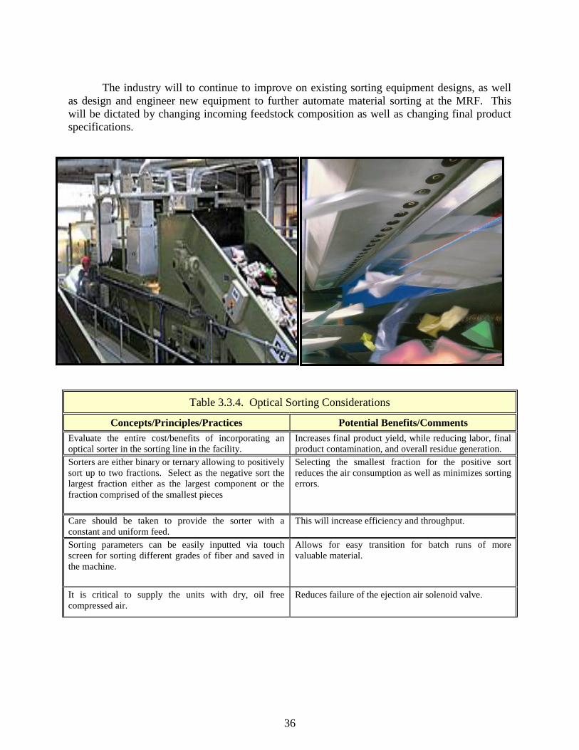
36
The industry will to continue to improve on existing sorting equipment designs, as well
as design and engineer new equipment to further automate material sorting at the MRF. This
will be dictated by changing incoming feedstock composition as well as changing final product
specifications.
Table 3.3.4. Optical Sorting Considerations
Concepts/Principles/Practices Potential Benefits/Comments
Evaluate the entire cost/benefits of incorporating an
optical sorter in the sorting line in the facility.
Increases final product yield, while reducing labor, final
product contamination, and overall residue generation.
Sorters are either binary or ternary allowing to positively
sort up to two fractions. Select as the negative sort the
largest fraction either as the largest component or the
fraction comprised of the smallest pieces
Selecting the smallest fraction for the positive sort
reduces the air consumption as well as minimizes sorting
errors.
Care should be taken to provide the sorter with a
constant and uniform feed.
This will increase efficiency and throughput.
Sorting parameters can be easily inputted via touch
screen for sorting different grades of fiber and saved in
the machine.
Allows for easy transition for batch runs of more
valuable material.
It is critical to supply the units with dry, oil free
compressed air.
Reduces failure of the ejection air solenoid valve.

37
3.4 SPECIAL MATERIALS CONSIDERATIONS
The following subsections discuss processing issues relating to glass, plastic and
aluminum.
3.4.1 GLASS RECOVERY AND PROCESSING
Glass breakage during handling at material recovery facilities (MRFs) decreases the
ability to effectively identify and remove contaminants and to sort for color. Reduction in
breakage means lower production of unsortable mixed color glass. This residual material cannot
be sorted and must be removed in processing and handled for disposal, or channeled to lower
value applications. Inexpensive design and procedure modifications can boost program revenues
(or reduce the loss) from the sale of cullet to manufacturers.
With the advance of specialized glass recycling(Beneficiation) facilities, most MRF‘s
will purposely break and screen the glass early in the sorting process. Multi deck glass breaking
screens can provide a higher quality product then a single screen. The screened glass (along with
small contaminants) is then mechanically and optically sorted at the glass recycling facilities.
Major points of breakage after collection include ―tipping‖ activity, where glass
containers are unloaded at the MRF, at feeding and conveying points within processing lines, and
whenever containers are handled with heavy equipment.
Studies have shown that modifications in glass
handling at recovery facilities can reduce breakage rates,
lowering production of mixed residuals. The
modifications include changes in design such as lowered
tipping heights, the addition of deflection ramps, and the
installation of rubber baffles at impact points. Procedural
changes include reducing tipping and handling speeds,
collection vehicle compaction strategies, and tipping floor
loader operation. Minimizing handling steps is the key
strategy for achieving efficient recovery of glass containers.
Deflection ramps placed below tipping points effectively reduce drop distances and can
be faced with abrasive-resistant, shock-absorbent plastic to further reduce impact. Drop chutes
also reduce drop distances and encourage containers to ―roll‖ rather than break on each other,
and can be implemented at in-feed hoppers or conveyor ends. Ramps and chutes should be
angled between 30 and 45 degrees to achieve impact reduction with enough slope to prevent
hang-ups.
Rubber or synthetic baffles represent one of the most effective and least expensive
methods of reducing glass breakage. Baffles reduce impact speed and deflect drop angles, and
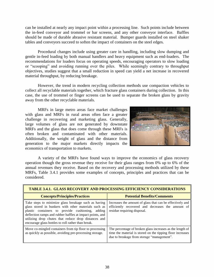
38
can be installed at nearly any impact point within a processing line. Such points include between
the in-feed conveyor and trommel or bar screens, and any other conveyor interface. Baffles
should be made of durable abrasive resistant material. Bumper guards installed on steel shaker
tables and conveyors succeed to soften the impact of containers on the steel edges.
Procedural changes include using greater care in handling, including slow dumping and
gentle in-feed loading by both manual handlers and heavy equipment such as end-loaders. The
recommendations for loaders focus on operating speeds, encouraging operators to slow loading
or ―scooping‖ and avoiding running over the piles. While seemingly contrary to throughput
objectives, studies suggest that a small reduction in speed can yield a net increase in recovered
material throughput, by reducing breakage.
However, the trend in modern recycling collection methods use compaction vehicles to
collect all recyclable materials together, which fracture glass containers during collection. In this
case, the use of trommel or finger screens can be used to separate the broken glass by gravity
away from the other recyclable materials.
MRFs in large metro areas face market challenges
with glass and MRFs in rural areas often face a greater
challenge in recovering and marketing glass. Generally,
large volumes of glass are not generated by downstate
MRFs and the glass that does come through these MRFs is
often broken and contaminated with other materials.
Additionally, the weight of glass and the distance from
generation to the major markets directly impacts the
economics of transportation to markets.
A variety of the MRFs have found ways to improve the economics of glass recovery
operation though the gross revenue they receive for their glass ranges from 0% up to 6% of the
annual revenues they receive. Based on the recovery and processing methods utilized by these
MRFs, Table 3.4.1 provides some examples of concepts, principles and practices that can be
considered.
TABLE 3.4.1. GLASS RECOVERY AND PROCESSING EFFICIENCY CONSIDERATIONS
Concepts/Principles/Practices Potential Benefits/Comments
Take steps to minimize glass breakage such as having
glass stored in bunkers with other materials such as
plastic containers to provide cushioning, adding
deflection ramps and rubber baffles at impact points, and
utilizing drop chutes that reduce drop distances and
encourage glass bottles to roll rather than break.
Increases the amount of glass that can be effectively and
efficiently recovered and decreases the amount of
residue requiring disposal.
Move co-mingled containers from tip floor to processing
as quickly as possible, avoiding pre-processing storage.
The percentage of broken glass increases as the length of
time the material is stored on the tipping floor increases
due to breakage from storage ―management‖.

39
TABLE 3.4.1. GLASS RECOVERY AND PROCESSING EFFICIENCY CONSIDERATIONS
(CONT’D)
Concepts/Principles/Practices Potential Benefits/Comments
If distances to major glass markets are too great,
consider alternative local markets such as municipal
highway departments, gravel pit operations, and
sandblasting companies.
May not have to color sort glass or remove all
contaminants. Transportation costs may also be reduced.
Glass crushing may or may not be necessary depending
on the local market.
Conduct an analysis to determine if crushing the glass
prior to shipment to market could reduce long-term
transportation costs.
In one example, a community is not crushing its glass
prior to delivery to market. Revenues received for the
glass do not cover the cost of transportation. Crushing
improves over-the-road weights and transportation costs
resulting in net revenue for materials. The investment
payback period for purchase and operation of a glass
crusher was estimated at approximately one year.
If there is little to no difference in the price received for
color sorted glass (green and amber) and mixed glass, do
not color sort.
Improves sorting efficiencies and materials handling in
moving containers of sorted glass around.
If no markets are available for certain categories of glass
(i.e., green glass, mixed glass), minimize its handling by
negatively sorting it off the end of the conveyor with
other residues going to disposal.
Reduces handling costs.
Additional glass containers can be recovered using a bin
nearby while sorting other materials (i.e., fibers, metals,
plastics) and throwing the occasional glass container in
the bin.
Utilize a specially fabricated chute toward the front of
the sorting line. When sorting other materials the first
sorter will pull out the occasional glass container and
throw it down the chute, which empties into a designated
bin for glass just below the elevated sorting line.
If the identified glass markets do not require color
sorting or crushing, eliminate these activities to
minimize the handling of glass as much as possible.
For example, the glass stream, which comes into the
facility as a separate stream, is pushed into a bunker that
empties into an inclined conveyor hopper. The material
travels up the conveyor and out the sidewall of the
facility. From there it drops 10 feet into a roll-off box,
which is delivered to the local highway department for
use as roadbed aggregate. In this case the drop of 10 feet
into the roll-off box breaks up the glass and helps
improve the transportation costs by increasing the over-
the-road weight of the load.
If glass is crushed prior to marketing, consider a feed
system that will automatically feed the glass to the
crusher with minimal labor involvement. An example is
a specially designed holding container that the glass is
thrown into during the sorting process. The holding
container is designed so that it fits in the hopper of the
glass crusher and has a manually operated trap door
toward the bottom of the holding container. Using a
forklift, the container is positioned in the crusher hopper
and the operator pulls a cord to lift the trap door. The
glass self-feeds into the hopper.
Quicker, safer, and more efficient than hand feeding
glass containers into the glass crusher.

40
3.4.2 PLASTICS RECOVERY AND PROCESSING
Most purchasers of recycled plastic understand the difficulty for suppliers to produce
bales that are 100 percent pure, particularly HDPE and
PET bottles generated from curbside collection programs
where different recyclable materials are commingled.
Most allow some flexibility in the types and levels of
contaminants they accept. While some contaminants may
be allowable, every reasonable effort should be made to
remove contaminants prior to baling. Adhering to the
following guidelines will improve the likelihood of
producing bales of plastic bottles that meet the majority of
buyer specifications:
• Design educational materials to help minimize the inclusion of non-acceptable resin
types.
• Make reasonable efforts to have generators remove caps, closures, rings and safety seals.
• Determine if oil and other automotive fluid bottles are acceptable.
• Containers should be completely free of contents before baling.
• Train sorters to recognize specific contaminant items such as PVC bottles.
• Produce bales with densities between 15 and 20 pounds per cubic foot.
• Produce bales with dimensions of 30‖x42‖x48‖ or 30‖x48‖x60‖ to optimize truckload
shipping weights.
• Use non-corrosive galvanized metal wire for baling.
• Use the minimum number of bale wires required to maintain bale integrity.
• Apply single wires wrapped in one direction to facilitate debaling.
Automated Systems Technology
Why is automated sorting necessary? According to the American Chemistry Council
(ACC), the total pounds of plastic bottles recycled reached a record high 2.410 billion pounds in
2008. NAPCOR reported 1.4515 billion pounds of PET bottles collected for recycling in 2008,
while ACC reported 936.7 million pounds of HDPE bottles were collected for recycling in 2008.
In addition, Moore Recycling Associates reported that
325.44 million lbs. of non-bottle rigid plastics were
collected for recycling. In the same study, Moore
indicated 1/3 of the 100 largest communities collect
non-bottle rigid.
Optical sorters manufacturers offer machines of
scalable width to meet the capacity of even the largest
capacity MRF‘s. Up to 20 tons/hr of plastics containers,
with accuracies ranging from 92 to 99.9% as per
manufacturer specifications. In the actual field applications the accuracy is lower due mainly to
round bottles rolling away from the expected rejection point, contaminants attached to bottles
and labels that can result in sensor misreadings.

41
The evolution of the technology in the last five years has resulted in equipment with
better electronics, increased sensitivity and ternary sorts,
which allows a MRF operator to positively sort HDPE and
PET while the rest of commingled material are negatively
sorted.
The number of manufacturers of optical sorting
equipment for plastics has grown from 8 reported by Ron
Perkins in 2006, to 18 identified by Kim Holmes in her
presentation at the 2010 Plastics Recycling Conference in
Austin, TX.
The typical optical sorting system consists of an
accelerating belt conveyor running at speeds
close to 500 feet per minute, a sensing unit and a
pneumatic ejection system.
The majority of the automated system
sort different plastics containers according to resin identification and color. The resin
identification is based on NIR (near Infra Red), Laser or X-rays technology, while color is
identified using Vision Technology (CCD linear cameras, CCPD) and Spectroscopy.
Ternary systems reject two
positively sorted streams either by
resin or color type.

42
TABLE 3.4.2. PLASTICS RECOVERY AND PROCESSING EFFICIENCY CONSIDERATIONS
Concepts/Principles/Practices Potential Benefits/Comments
Run plastic containers thru an aggressive size
screener prior to any manual or automated sorting.
Eliminates smaller plastic pieces, dirt and especially broken
glass which have a negative effect on manual sorting,
equipment wear and plastics bale quality.
Forced air separation of plastic and glass containers
is preferable to mechanical separation.
Properly designed air classifiers can separate plastics from
glass with limited crossover of glass to the light line or
plastic to the heavy line.
In general, it may not be possible to achieve size and weight
based separation in one step for materials that have similar
size and weight. For example, a screen may be used to
screen out smaller containers (such as UBCs and single
serve PET containers) from larger containers; but then a
second process device (such as an Eddy Current) may be
needed to separate the UBCs from the single serve
containers.
Use two levels of sorting on plastics before
considering granulating.
The average measured contamination levels after manual
sorting are generally too high to meet minimum
specifications for sale of flake or pellets to most reclaimers
or end users. Evaluation of granulating plastics at a MRF
should include secondary sorting (either manual or
automated) to further reduce contamination levels.
When sorting other resins beyond the 1 (PET) and 2
(HPDE) bottles, consider the use of a smaller
dedicated baler.
For small and medium size MRFs this represents a
considerable saving of space by eliminating the need of
storage bunkers to hold a sufficient amount of plastic
containers to make a bale
Optical sorters are user friendly and provide great
flexibility to modify the sorting parameters.
Adaptability to changing market conditions.
Consider a split operation in a single , enabling the
sorting of different streams at each half of the
machine instead of two individual units.
Cost saving can be realized by installing a large unit and
running either four different positive sorts or a double pass
for higher material quality.
The installation of the Optical sorter should allow for
easy maintenance access to inspect and clean the unit
optical components
The optical sorter loses effectiveness due to accumulation
of dust on the sensors and requires periodic cleaning..
The processing units are enclosed in a controlled
atmosphere where air temperature and humidity are kept
within close values for proper operation. Air filters need to
be serviced often in dusty environments.
Provide either a phone line or internet connection to
the machine.
Most Optical Sorters conduct automated periodic updates
and calibration directly with its factory.
For a more extensive and technically detailed discussion of best practices in recycling
HDPE and PET, the reader is referred to the guides prepared by the Clean Washington Center.
The full text of these guides is available on-line at http://www.cwc.org/.

43
3.4.3 ALUMINUM RECOVERY AND PROCESSING
Due to the high value of recovered aluminum, buyers are not interested in paying UBC
prices for broken glass and chips of plastic. Buyers wish to purchase only contaminant-free
aluminum cans and have stringent quality expectations that include quantification of levels of
moisture, heavy metal, dirt and ferrous metal concentrations in UBC shipments.
When mechanically separating UBCs, there are seven essential processing elements
needed to generate high-quality UBCs from a residential commingled container stream:
• Agitation and tumbling action for dirt and moisture reduction and drying of the UBCs
• Screening of UBCs prior to manual quality control to remove remaining non-UBC
fragments,
• Size classification and screening, upstream of the eddy-current separator, to optimize the
eddy-current process.
• High-strength electromagnetic separation upstream and downstream of the eddy-current
separator.
• A manual (visual) quality control inspection prior to baling or flattening, and
• Visual inspection after baling and if required reprocessing.
• Quality control checkpoints established throughout the line with trained workers.
3.5 BALING MATERIALS
If a recycling facility is going to own only one piece of stationary machinery, a baler will
likely be the equipment of choice. Baling of sorted fibers, metals, and plastics offers a wide
variety of advantages in the operation of a MRF. Among these are improved on-site storage,
improved efficiencies in getting materials to market, and, in most cases, wider marketability and
higher pricing.
3.5.1 PRE-BALING STORAGE
Sorted materials are often stored temporarily to accumulate sufficient quantities of
individual materials prior to conveying materials to the baler. Having adequate pre-baling
storage is essential to maximizing baler productivity and reducing the labor costs associated with
emptying bunkers and cages. It is at this stage that inefficiencies in double-handling materials
are often encountered as materials are moved from sorting areas to storage, then from storage to
baling operations. This is frequently seen at smaller MRFs that sort into gaylords, and then stack
them for storage until baleable quantities are accumulated.
Some MRFs have employed dedicated balers with hoppers for each
baleable container commodity. However this system suffers from lack
of sufficient storage in the hoppers, extra maintenance associated with
the balers, and low bale densities associated with the smaller balers
used.
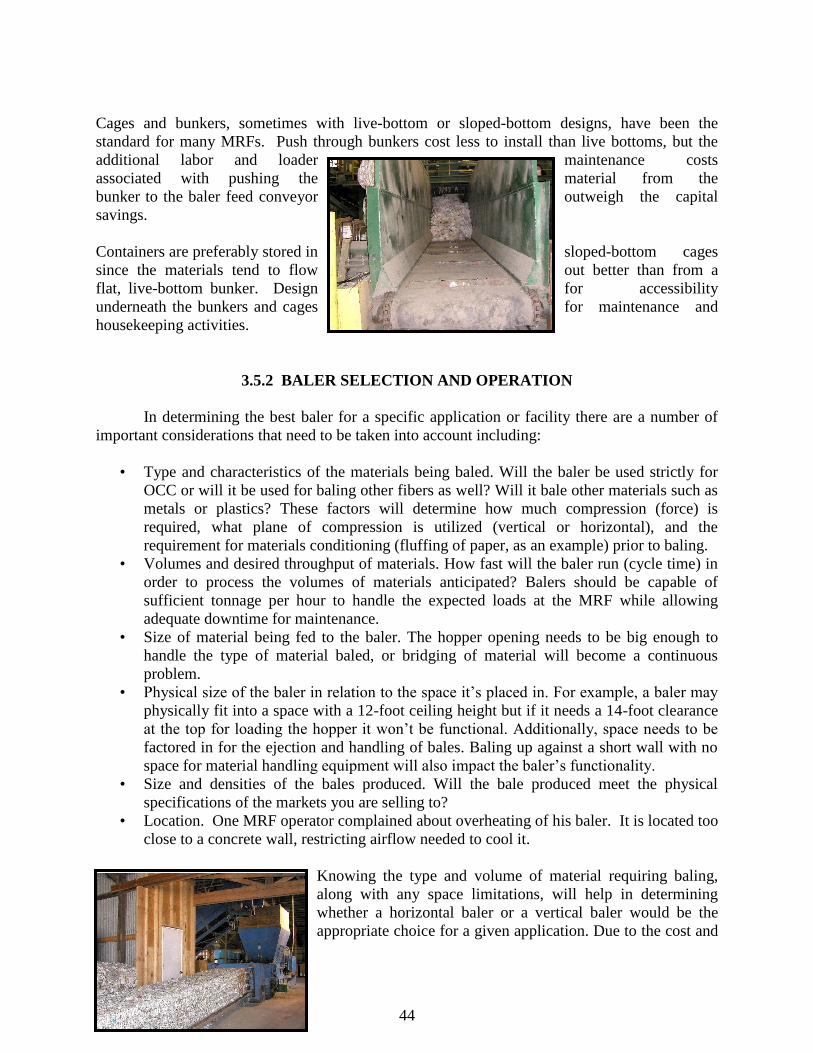
44
Cages and bunkers, sometimes with live-bottom or sloped-bottom designs, have been the
standard for many MRFs. Push through bunkers cost less to install than live bottoms, but the
additional labor and loader maintenance costs
associated with pushing the material from the
bunker to the baler feed conveyor outweigh the capital
savings.
Containers are preferably stored in sloped-bottom cages
since the materials tend to flow out better than from a
flat, live-bottom bunker. Design for accessibility
underneath the bunkers and cages for maintenance and
housekeeping activities.
3.5.2 BALER SELECTION AND OPERATION
In determining the best baler for a specific application or facility there are a number of
important considerations that need to be taken into account including:
• Type and characteristics of the materials being baled. Will the baler be used strictly for
OCC or will it be used for baling other fibers as well? Will it bale other materials such as
metals or plastics? These factors will determine how much compression (force) is
required, what plane of compression is utilized (vertical or horizontal), and the
requirement for materials conditioning (fluffing of paper, as an example) prior to baling.
• Volumes and desired throughput of materials. How fast will the baler run (cycle time) in
order to process the volumes of materials anticipated? Balers should be capable of
sufficient tonnage per hour to handle the expected loads at the MRF while allowing
adequate downtime for maintenance.
• Size of material being fed to the baler. The hopper opening needs to be big enough to
handle the type of material baled, or bridging of material will become a continuous
problem.
• Physical size of the baler in relation to the space it‘s placed in. For example, a baler may
physically fit into a space with a 12-foot ceiling height but if it needs a 14-foot clearance
at the top for loading the hopper it won‘t be functional. Additionally, space needs to be
factored in for the ejection and handling of bales. Baling up against a short wall with no
space for material handling equipment will also impact the baler‘s functionality.
• Size and densities of the bales produced. Will the bale produced meet the physical
specifications of the markets you are selling to?
• Location. One MRF operator complained about overheating of his baler. It is located too
close to a concrete wall, restricting airflow needed to cool it.
Knowing the type and volume of material requiring baling,
along with any space limitations, will help in determining
whether a horizontal baler or a vertical baler would be the
appropriate choice for a given application. Due to the cost and
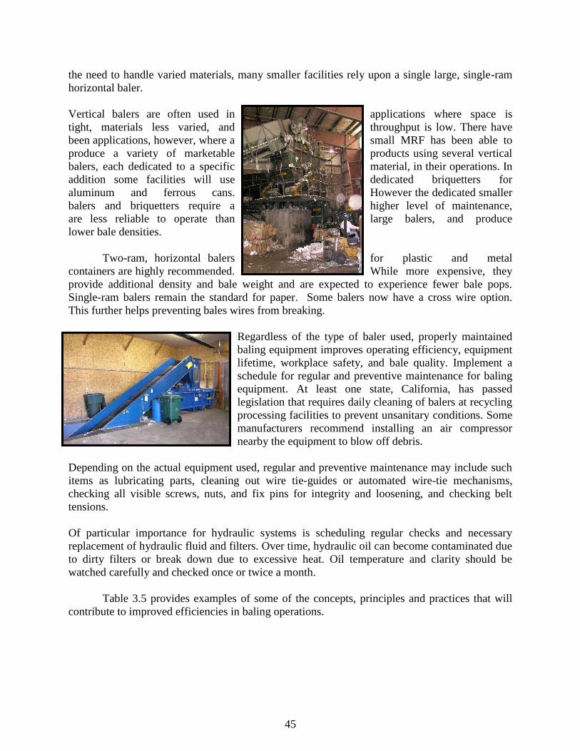
45
the need to handle varied materials, many smaller facilities rely upon a single large, single-ram
horizontal baler.
Vertical balers are often used in applications where space is
tight, materials less varied, and throughput is low. There have
been applications, however, where a small MRF has been able to
produce a variety of marketable products using several vertical
balers, each dedicated to a specific material, in their operations. In
addition some facilities will use dedicated briquetters for
aluminum and ferrous cans. However the dedicated smaller
balers and briquetters require a higher level of maintenance,
are less reliable to operate than large balers, and produce
lower bale densities.
Two-ram, horizontal balers for plastic and metal
containers are highly recommended. While more expensive, they
provide additional density and bale weight and are expected to experience fewer bale pops.
Single-ram balers remain the standard for paper. Some balers now have a cross wire option.
This further helps preventing bales wires from breaking.
Regardless of the type of baler used, properly maintained
baling equipment improves operating efficiency, equipment
lifetime, workplace safety, and bale quality. Implement a
schedule for regular and preventive maintenance for baling
equipment. At least one state, California, has passed
legislation that requires daily cleaning of balers at recycling
processing facilities to prevent unsanitary conditions. Some
manufacturers recommend installing an air compressor
nearby the equipment to blow off debris.
Depending on the actual equipment used, regular and preventive maintenance may include such
items as lubricating parts, cleaning out wire tie-guides or automated wire-tie mechanisms,
checking all visible screws, nuts, and fix pins for integrity and loosening, and checking belt
tensions.
Of particular importance for hydraulic systems is scheduling regular checks and necessary
replacement of hydraulic fluid and filters. Over time, hydraulic oil can become contaminated due
to dirty filters or break down due to excessive heat. Oil temperature and clarity should be
watched carefully and checked once or twice a month.
Table 3.5 provides examples of some of the concepts, principles and practices that will
contribute to improved efficiencies in baling operations.
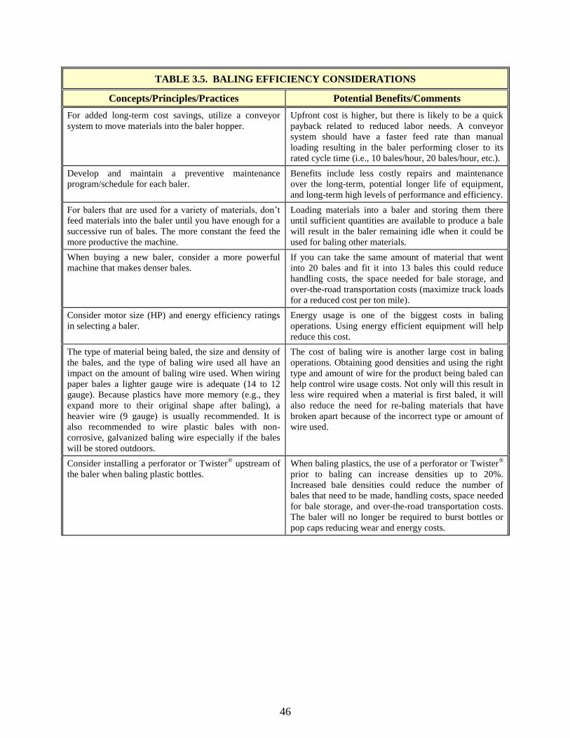
46
TABLE 3.5. BALING EFFICIENCY CONSIDERATIONS
Concepts/Principles/Practices Potential Benefits/Comments
For added long-term cost savings, utilize a conveyor
system to move materials into the baler hopper.
Upfront cost is higher, but there is likely to be a quick
payback related to reduced labor needs. A conveyor
system should have a faster feed rate than manual
loading resulting in the baler performing closer to its
rated cycle time (i.e., 10 bales/hour, 20 bales/hour, etc.).
Develop and maintain a preventive maintenance
program/schedule for each baler.
Benefits include less costly repairs and maintenance
over the long-term, potential longer life of equipment,
and long-term high levels of performance and efficiency.
For balers that are used for a variety of materials, don‘t
feed materials into the baler until you have enough for a
successive run of bales. The more constant the feed the
more productive the machine.
Loading materials into a baler and storing them there
until sufficient quantities are available to produce a bale
will result in the baler remaining idle when it could be
used for baling other materials.
When buying a new baler, consider a more powerful
machine that makes denser bales.
If you can take the same amount of material that went
into 20 bales and fit it into 13 bales this could reduce
handling costs, the space needed for bale storage, and
over-the-road transportation costs (maximize truck loads
for a reduced cost per ton mile).
Consider motor size (HP) and energy efficiency ratings
in selecting a baler.
Energy usage is one of the biggest costs in baling
operations. Using energy efficient equipment will help
reduce this cost.
The type of material being baled, the size and density of
the bales, and the type of baling wire used all have an
impact on the amount of baling wire used. When wiring
paper bales a lighter gauge wire is adequate (14 to 12
gauge). Because plastics have more memory (e.g., they
expand more to their original shape after baling), a
heavier wire (9 gauge) is usually recommended. It is
also recommended to wire plastic bales with non-
corrosive, galvanized baling wire especially if the bales
will be stored outdoors.
The cost of baling wire is another large cost in baling
operations. Obtaining good densities and using the right
type and amount of wire for the product being baled can
help control wire usage costs. Not only will this result in
less wire required when a material is first baled, it will
also reduce the need for re-baling materials that have
broken apart because of the incorrect type or amount of
wire used.
Consider installing a perforator or Twister® upstream of
the baler when baling plastic bottles.
When baling plastics, the use of a perforator or Twister®
prior to baling can increase densities up to 20%.
Increased bale densities could reduce the number of
bales that need to be made, handling costs, space needed
for bale storage, and over-the-road transportation costs.
The baler will no longer be required to burst bottles or
pop caps reducing wear and energy costs.

47
Table 3.5 Baling Efficiency Considerations (con’t.)
Concepts/Principles/Practices Potential Benefits/Comments
For in-feed quality control checks, instead of stationing
pickers adjacent to below-grade conveyor hoppers or
standing on above grade hopper frames, construct safe
and secure elevated platforms along the inclined
conveyors for retrieval/removal of contaminants or for
breaking up bulky slugs that could cause bridging.
An elevated platform will eliminate the need for
excessive bending, stretching, and balancing on
structures being used for purposes other than what they
were designed for. This in turn should lead to an
improved efficiency and effectiveness in the quality
control operation.
Maintain proper clearances for door swing on closed-end
hydraulic balers. A best practice is to outline the door
swing area with paint on the floor of the facility to
identify the area in which to stay clear.
Baler doors are under pressure and they open with
tremendous force. Operating personnel must maintain a
safe distance from the door swing area when ejecting
bales.
Following these simple rules will assist in providing uniform bales that will improve de-
baling operations and reduce processing wastes at the end-user's mill. In addition, proper mainte-
nance will maximize the performance, economics and safety of baling operations.
Safety Issues. There are a number of safety issues related to operating a baling system.
All employees feeding or operating baling equipment should be trained in proper equipment
operation. Equip all balers and feed mechanisms with emergency shut-off switches that will cut
power to the system in the event of an emergency or safety hazard, or when maintenance is
needed.
Operating personnel should never climb into or place any portion of their body into the
baler chamber, unless the operator is absolutely certain that power to the system has been cut and
locked out. Serious and sometimes fatal accidents have occurred as a result of an operator
entering the baling chamber or trying to clear blocked material during a compaction cycle. There
are proper procedures for clearing jammed materials, and all operators should be thoroughly
trained in those procedures.
Due to the number of injuries and deaths involving balers and other compaction
equipment, the National Institute of Occupational Safety and Health (NIOSH) has prepared a
report that illustrates the safety risks of operating baling equipment and provides
recommendations for preventing injury: ―NIOSH Alert: Preventing Deaths and Injuries While
Compacting or Baling Refuse Material,‖ DHHS (NIOSH) Publication No. 2003-124. This
publication is available from 1-800-35-NIOSH or from the NIOSH web page at
http://www.cdc.gov/niosh/docs/2003-124/ .
3.6 PRODUCT STORAGE
Once incoming materials have been received and processed they go into product storage
to await delivery to markets. Having adequate storage space for final product that will also
protect the product from degradation while awaiting delivery to market is crucial. If such storage
space is not provided, a variety of problems can occur including selling product prematurely

48
(when not enough has accumulated to provide a full load or to take advantage of rising
commodity prices) and receiving low prices or having loads rejected due to poor quality and
product contamination. This last issue can lead to further problems with markets not wanting to
purchase products from a particular MRF or purchasing materials only on a spot market basis.
Preferably all materials awaiting marketing should be stored inside or at least under
cover. This is especially true of fibers, which will absorb moisture when wet resulting in a
degraded product. Excessive moisture can skew material weights or lead to the formation of ice,
making baled material more difficult to handle and process.
Materials that are stored outside should be stored in such a way as to minimize
contamination (i.e., away from other materials that could contaminate the stored product, on
concrete pads to minimize the accumulation of dirt and mud, etc.) and should be delivered to
market in as short a time period as possible. If a product will be in storage for an extended period
of time it should not be stored outside. Ferrous will rust over time when wet and HDPE plastics
will be degraded when exposed to ultra-violet light for several weeks. Commodities such as
glass are more weather resistant but even then the outside storage of uncovered bins or roll-off
containers of glass will be prone to collection of dirt and other contaminants.
3.6.1 BALE HANDLING AND STORAGE
Properly handled and stored bales help maintain
the quality of prepared commodities prior to sale and help
improve workplace safety. In general, baled materials
should be stored in a fashion that keeps them clean and
dry with limited exposure to sunlight (sunlight can cause
ultraviolet degradation of fiber and plastics). Bales should
preferably be stored indoors. If they must be stored
outdoors, they should be covered to limit exposure to
moisture or sunlight. Bales should be stored on pallets or
on clean, dry surfaces to avoid introduction of
contaminants. This is particularly true in materials
recovery facilities where many different types of materials are processed.
Bales should always be transported in a fashion that keeps them elevated off the floor
surface. When transporting bales throughout a facility, take caution not to push bales directly
across the floor surface, as this may embed unwanted contaminants into the bale. Do not store
bales in close proximity to granulators or other processing equipment to prevent the introduction
of airborne contaminants.
Minimizing the number of times a bale is handled is the best practice for maintaining bale
integrity through storage, loading and shipping. Excessive handling increases the probability of
bale breakage and introduction of contaminants. For these reasons, when stacking bales of
recyclable materials, each commodity must be stacked independently from the other, so that
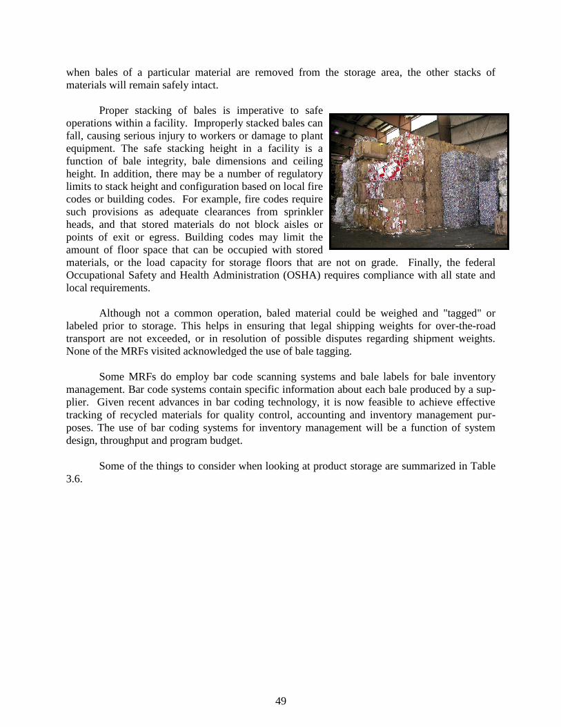
49
when bales of a particular material are removed from the storage area, the other stacks of
materials will remain safely intact.
Proper stacking of bales is imperative to safe
operations within a facility. Improperly stacked bales can
fall, causing serious injury to workers or damage to plant
equipment. The safe stacking height in a facility is a
function of bale integrity, bale dimensions and ceiling
height. In addition, there may be a number of regulatory
limits to stack height and configuration based on local fire
codes or building codes. For example, fire codes require
such provisions as adequate clearances from sprinkler
heads, and that stored materials do not block aisles or
points of exit or egress. Building codes may limit the
amount of floor space that can be occupied with stored
materials, or the load capacity for storage floors that are not on grade. Finally, the federal
Occupational Safety and Health Administration (OSHA) requires compliance with all state and
local requirements.
Although not a common operation, baled material could be weighed and "tagged" or
labeled prior to storage. This helps in ensuring that legal shipping weights for over-the-road
transport are not exceeded, or in resolution of possible disputes regarding shipment weights.
None of the MRFs visited acknowledged the use of bale tagging.
Some MRFs do employ bar code scanning systems and bale labels for bale inventory
management. Bar code systems contain specific information about each bale produced by a sup-
plier. Given recent advances in bar coding technology, it is now feasible to achieve effective
tracking of recycled materials for quality control, accounting and inventory management pur-
poses. The use of bar coding systems for inventory management will be a function of system
design, throughput and program budget.
Some of the things to consider when looking at product storage are summarized in Table
3.6.
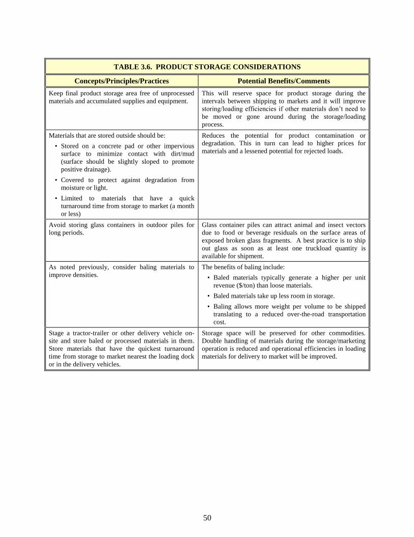
50
TABLE 3.6. PRODUCT STORAGE CONSIDERATIONS
Concepts/Principles/Practices Potential Benefits/Comments
Keep final product storage area free of unprocessed
materials and accumulated supplies and equipment.
This will reserve space for product storage during the
intervals between shipping to markets and it will improve
storing/loading efficiencies if other materials don‘t need to
be moved or gone around during the storage/loading
process.
Materials that are stored outside should be:
• Stored on a concrete pad or other impervious
surface to minimize contact with dirt/mud
(surface should be slightly sloped to promote
positive drainage).
• Covered to protect against degradation from
moisture or light.
• Limited to materials that have a quick
turnaround time from storage to market (a month
or less)
Reduces the potential for product contamination or
degradation. This in turn can lead to higher prices for
materials and a lessened potential for rejected loads.
Avoid storing glass containers in outdoor piles for
long periods.
Glass container piles can attract animal and insect vectors
due to food or beverage residuals on the surface areas of
exposed broken glass fragments. A best practice is to ship
out glass as soon as at least one truckload quantity is
available for shipment.
As noted previously, consider baling materials to
improve densities.
The benefits of baling include:
• Baled materials typically generate a higher per unit
revenue ($/ton) than loose materials.
• Baled materials take up less room in storage.
• Baling allows more weight per volume to be shipped
translating to a reduced over-the-road transportation
cost.
Stage a tractor-trailer or other delivery vehicle on-
site and store baled or processed materials in them.
Store materials that have the quickest turnaround
time from storage to market nearest the loading dock
or in the delivery vehicles.
Storage space will be preserved for other commodities.
Double handling of materials during the storage/marketing
operation is reduced and operational efficiencies in loading
materials for delivery to market will be improved.

51
3.7 RESIDUALS MANAGEMENT
Even the best recycling facilities generate a waste stream. Excess residuals, however, can
be a costly inefficiency. A study of MRF operations by the American Plastics Council pegged
the mean cost of processing residues at $85 a ton. A trend in MRF design includes incorporating
equipment that reduces residuals.
Residues from recycling facilities result from two major
sources; unwanted materials mixed with incoming
recyclables and recyclables that are not recovered. In
the latter case, a periodic inspection of the residuals
from your facility can provide clues to inefficient
operations, which can be corrected internally or if
needed, by adding equipment. Residual rates decreased
and plastic recovery increased when optical plastic
sorters were added to the line in existing MRF‘s.
Generally resorting residuals is not cost effective,
however, a regular, e.g. weekly, sort of a sample of
residues to determine the percentage of recoverable recyclables and the percentage of unwanted
or prohibitive materials can be a valuable management tool.
Reducing incoming contamination requires constant education and communication with the
generators. Whether your source of materials is commercial accounts, curbside programs or
drop-off boxes, public education can have a dramatic effect on the quality of materials coming in
the front door. An Oregon MRF was finding large quantities of scrap metal in its residues before
discovering that one of its curbside programs was targeting scrap as a recyclable.
Establish a load checking policy and procedures for providing feedback to sources of
excess contamination. MRFs should use video or still photo records to give feedback to
suppliers regarding the quality of materials received. Showing actual video or photos of actual
contamination gives the suppliers the information they need to recognize the specific materials
that are not acceptable so they can go back to the collection sources with education to prevent
future contamination.
Develop brochures or other educational materials describing materials that are
acceptable, unacceptable and why. If you are a private operator, seek out partnerships with
public agencies interested in promoting recycling to assist in public education efforts.
The type of collection program selected for a community program can also impact the
amount of residuals received. A March 2004 American Forest and Paper Association report
found an average ―residue percent‖ of 14.4 percent for programs using single-stream collection
compared to 6.8 percent for dual-stream collection. (Note: The residual rates reported by the
single stream facilities interviewed for this manual reported rates much lower than this average.)

52
Considerations that need to be taken into account when calculating % residue include
contaminants shipped with the final product. Unacceptable material coming into the MRF
should not be included because ????? the system was not designed to remove them .
Handling the inevitable rejects and residue material is usually done in one of three ways:
depositing them in dumpsters or roll-offs, baling them or using compactors. Transporting loose
material in roll-offs can be expensive and baling can reduce this transportation cost. However,
these rejects often contain materials such as glass fragments and metals that can cause excessive
wear and maintenance on the baler. Baling also risks introducing contaminants into following
bales of recyclables and interrupts the baler‘s normal operations. Compactors are preferred as
their maintenance costs are lower and their use is less disruptive of MRF operations.
3.8 MAINTENANCE
For a materials recovery facility, next to operating costs, the second highest cost is
equipment and facility maintenance. Profits can be wiped out by the cost to replace or repair
equipment that was not properly maintained and failed prematurely. A good preventive
maintenance program is the best way to keep equipment on-line and functioning. Common
threads to an effective program include:
• Ensure equipment has adequate capacity to allow for scheduled downtime. When
equipment runs at 99% capacity from day one, maintenance suffers.
• Maintenance can be scheduled so as not to impact operating efficiency. Take advantage
of days when incoming material is lighter than average to shut down early. Alternate
lunch breaks between processing and maintenance crews. If necessary, sacrifice some
overtime on the weekend.
• Teach equipment operators to ―get in tune‖ with how the machines run and to keep alert
for maintenance concerns. By noticing an incorrectly tracking belt, a wearing part, or an
unusual noise or vibration, knowledgeable staff can identify potential problems that
might eventually manifest themselves in a breakdown.
• Develop daily, weekly and monthly schedules for common maintenance tasks such as
visual inspection, lubrication, tightening belts and rollers, wear parts replacement and
cleaning confined spaces. Follow equipment manufacturer maintenance schedules and if
they are not adequate for the operation, adjust the schedule to reflect the equipment wear
rate.
• Consider the use of computer software to schedule and monitor maintenance activities
and control parts inventories. Maintain logs of maintenance, problems and downtime
associated with each piece of equipment. Historical records can provide clues to chronic
problems.
• Give maintenance staff the support they need to diagnose and fix problems to prevent
them from recurring.
• When designing or upgrading a MRF, include maintenance platforms as extensive as
possible for ease of servicing equipment.

53
3.9 TRANSPORTATION
Properly loaded trucks can ensure regulatory compliance with maximum legal shipping
weights, lessen the possibility of contamination, and prevent costly material losses and clean-up
expenses due to improper loading. Proper paperwork and weight verification for shipments can
help reduce disputes over material quality or quantity.
Prior to loading a truck, sweep the truck floor to
remove any potential contaminants. Never push bales
across the truck floor surface to prevent imbedding
potential contaminants in the bales. Shipments should
always be accompanied with a complete bill of lading,
certified weight slips, and preferably, a detailed packing
list from the shipper.
Work with your markets to be sure the bale sizes
proposed in their specifications will allow for the most
efficient truck loading and unloading. Make sure required bale configurations will not require
special loading, such as standing bales on end, to achieve required minimum shipping weights or
result in excessive ―air‖ space in trailers.
Facility operators should never load broken or partially broken bales. Never "jam" or
wedge bales into trucks, as this will adversely affect unloading and could possibly damage
equipment. Based on the actual bale density and the particular truck's legal gross shipping
weight, it may not be necessary to fill the truck to capacity. This can be determined by
calculating the number of bales that can be accommodated without exceeding the maximum
legal shipping weight provided by the carrier, based on the sum of individual bale weights. In
addition, a best practice is to record individual bale weights on a packing list that can be attached
to the bill of lading for the shipment.
In cases where the truck cannot be filled to capacity, bales should be distributed evenly
throughout the truck. This may require stacking some rows only two bales high instead of three.
The best practice is to distribute the bales along the entire truck floor, that is, from the nose to the
tail, even if the maximum stack height is not achieved.
In addition, when scheduling trucks for outgoing shipment, a best practice is to always
request that the carrier be equipped with "load locks" that are placed across the width of the truck
to prevent bales from falling and potentially breaking open during transport. It is also important
to specify the truck size you require when scheduling a shipment to make sure that you receive a
truck that can accommodate the required minimum shipping weight of your particular supplier.
While most trucks use either 48- or 53-foot trailers, some carriers use 45-foot trailers.
When loading bales three-high in a truck, it is recommended that the bottom bale of each
stack in a row be loaded singly, with the remaining two bales placed on top as a pair in a separate
pass. In this way, forklifts with two-stage hydraulic systems will not hit and possibly puncture

54
the roof of the truck. Similarly, when unloading, operators should take off the top two bales of a
stack first and then return for the bottom bale.
When receiving baled materials, trained personnel should visually inspect the load prior
to accepting it. Visual inspection will quickly identify the presence of excessive levels of
contaminants, such as unacceptable containers of other material types, moisture, or product
residues. Visual inspection can also assess general bale quality in terms of bale integrity. Broken
strapping or broken bales are easily identified. The basic rule of thumb throughout the industry is
that if contamination is visible on the exterior of the bale it is likely to be contained in the
interior of the bale. Therefore, poor bale appearance usually indicates poor overall material
quality. Visual identification of excessive levels of contamination on the bale exterior is grounds
for load rejection. To avoid disputes, it is always best to take photographs of any rejected
materials.
The best practice for determining the weight of a shipment is to weigh trucks empty and
full (referred to throughout the industry as the light and heavy weight) on certified 65-foot truck
scales. Certified scales are those that have been inspected by their respective regulatory agency
for weights and measures for accuracy. A general rule within the recycling industry is that the
receiver's weight takes precedence.
In cases where trailers are dropped for loading and unloading and picked up at a later
time, light and heavy weights can be taken on the trailer only. Many carriers that provide trailers
in this fashion have the trailer's empty weight documented.
TABLE 3.9. TRANSPORTATION CONSIDERATIONS
Concepts/Principles/Practices Potential Benefits/Comments
Maximize material weight delivered to market. Increase
load densities by baling (i.e., fibers, plastics, aluminum,
etc.) or crushing (i.e., glass). Ensure loads are "full"
loads.
In addition to improved over-the-road transportation
costs, many markets have a minimum load weight
requirement. Not meeting this requirement can often
lead to a financial penalty.

55
4.0 MARKETING
Established and secure long-term markets for materials are crucial to operating
efficiencies at MRFs. Those markets dictate how much and what kind of processing is required
as well as providing reliable outlets for processed materials and the necessary revenue for
continued operation of the MRF.
Materials to be marketed should be prepared in such a way as to meet delivery
specifications to the market (i.e., bales of a certain size and density, clean, minimal to zero
contaminants, etc.). Regardless of whether materials are sold to local markets (e.g., insulation
manufacturer), directly to larger regional, national markets (e.g., paper mills, glass cullet
markets), to a variety of markets via a commodity broker, or exported, having a written contract
will offer some protection from fluctuating prices or from having the market reject loads without
good reasons.
The conditions and requirements in a marketing agreement will vary widely. Items that
should be addressed in a marketing agreement, though not all-inclusive, include such things as:
• Material Specifications that need to be met by the processor (definition of contaminants,
• Minimum quantities and frequency of collections/deliveries;
• Delivery or pickup site;
• Price to be paid for materials and, if applicable, the formula used to determine the price to
be paid;
• Price reduction for non-spec material;
• Minimum per unit revenue (floor price) seller will receive for materials;
• What to do when value of commodity falls below the floor price;
• What party arranges for and pays for loading and transportation of materials to markets;
• Procedures for handling rejected loads; and
• Term of contract.
TABLE 4.0. MARKETING CONSIDERATIONS
Concepts/Principles/Practices Potential Benefits/Comments
If insufficient quantities of materials are
recovered to interest potential markets,
consolidating those materials with materials from
other counties or municipalities could help attract
the necessary markets. This approach is termed
"cooperative marketing."
The concept of cooperative marketing has been very effective
in a variety of locations and has given smaller generators of
recyclables more leverage in obtaining secure markets and
relatively stable prices.
If the economics associated with traditional
markets are unattractive (i.e., too costly to process
materials to meet specifications, too costly to
transport materials to distant markets, etc.)
consider developing local alternative markets for
some of the recovered materials.
Historically examples of alternative markets have included
animal bedding or local cellulose insulation manufacturers
(newspaper) or roadbed aggregate (glass). Though the revenue
received for these materials is generally low, the processing
and transportation costs are also generally low and there is a
cost avoidance if material is not disposed.

56
TABLE 4.0: MARKETING CONSIDERATIONS (CONT’D)
Concepts/Principles/Practices Potential Benefits/Comments
Balance marketing decisions for specific
materials on quantity of materials recovered,
processing cost, and revenue received.
For example, if the additional revenue generated from
marketing natural HDPE recovered in an operation is $3,000
more than if it was marketed along with the pigmented HDPE
but it costs $4,000 to sort and process this material the added
effort is not worth the added revenue.
Considering the types and quantities of materials
generated, assess the advantages and
disadvantages of marketing directly to an end-
market versus a broker or versus another MRF
with attractive processing.
There are a variety of advantages and disadvantages in going
directly to an end-market versus going through a broker. Some
of these include:
An end-market, such as a paper mill, is likely to give you a
higher price for a specific grade(s) of material if you can
guarantee the quality and the quantity they demand. Going
through a broker will usually result in a lower price per ton
since the broker takes a portion of the revenue.
Going through a broker will generally offer a wider variety
of markets (market diversity) and as a result they can shop
around for the best price. Selling directly to a mill may
limit the grades of paper they will be willing to purchase
and the price they can pay for that paper.
Communicate with other operations to see how
their contracts are structured and what their
markets offer in the way of service.
There are a variety of conditions and items that should be
addressed in a market contract to protect the seller from wild
fluctuations in the price paid for a specific commodity.
Understanding specifications that need to be met, the recourse a
seller has if a load is downgraded or rejected, responsibility for
arranging and paying for transportation to market, etc., should
be addressed in the contract to offer shared risk (and reward)
between the parties.
Beware of being ―over-brokered‖. Brokers may offer prices significantly below going market
rates. It pays to be aware of market prices and the price other
facilities are being paid for materials. Join marketing
associations to exchange ideas and information. Learn to ask
questions and read the trade journals. Negotiate equitable
brokerage fees.
Make sure that your buyers are reliable and will
pay you for the material they purchase at the price
they quoted.
Buyers that acquire your material and then go bankrupt do not
help you at all.
Don‘t change markets frequently for small
changes in prices.
If you are jumping around from buyer to buyer in a hot market,
you may lose your only market during the downturns. Markets
prefer reliable, long-term suppliers in the same way MRFs like
reliable, long-term markets.
Look globally for markets. Emerging markets, such as China, appear to be where the new
demand will continue to come from.
57
5.0 HEALTH AND SAFETY CONSIDERATIONS
Every MRF location has a duty to provide a safe place of work as well as safety to the general
public that may visit that location. Standards have been established for safety through the
Occupational Safety and Health Administration (OSHA) and American National Standards
Institute (ANSI) as well as local state or federal requirements. This section addresses the primary
elements of safety within a MRF. MRF operations contain many potential hazards that must be
identified and properly addressed. Each year many serious and fatal injuries occur within MRF
operations. Developing a formalized safety process will benefit each MRF operator by
establishing greater compliance with OSHA requirements and the reduction of risk within the
facility.
The different components of this section will outline important safety information that each MRF
should implement. Each component outlined should be addressed with the consideration of
potential language and communication issues. MRF locations typically have employee
populations that include more than one language. Safety is such an important topic that
communicating in the language of the employee population must be accomplished.
Because each MRF location is unique, the operator must evaluate their own operations and
determine how the related OSHA or other standards will apply to those specific operations. The
information contained in this section is designed to provide reference to the more common safety
issues and does not attempt to address all safety and health related issues.
5.1- Developing a Safety Process:
A safety process is a series of programs and activities that comprise a total health and safety
management program. A safety process is the most effective means to manage OSHA
requirements and prevent losses. The following is a brief outline of safety process elements for a
MRF operation. Successful management of safety issues will require activity in each of these
primary categories.
1. Written Health and Safety Programs
a. Written policies specific to the hazards associated with the MRF facility
2. Safety Training
a. Documented safety training addressing key exposure issues at the MRF facility
b. New Employee Safety Orientation
3. Accident Prevention Activities
a. Safety Committees
b. Self Inspections
c. Hiring Practices
d. Employee Communication
e. Job Hazard Analysis
f. Stretch & Flex Programs
4. Health Management Activities
a. Air quality evaluation and monitoring

58
b. Noise level evaluation and monitoring
c. Other Medically necessary prevention activities
5. Post Incident Activities
a. Accident Investigation
b. Post Accident Review
c. Early Return to Work Program
d. Coordination with Occupational Health Clinic
6. Benchmarking and Monitoring
a. OSHA Recordkeeping
b. Accident Prevention Goal Setting
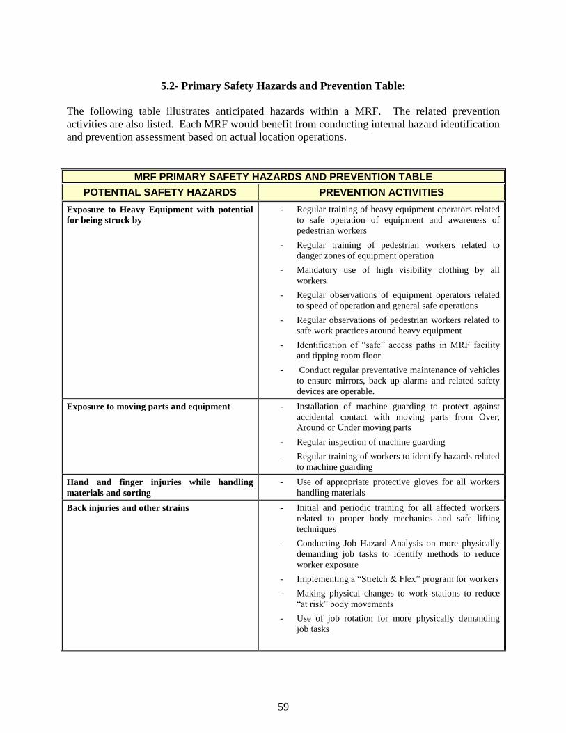
59
5.2- Primary Safety Hazards and Prevention Table:
The following table illustrates anticipated hazards within a MRF. The related prevention
activities are also listed. Each MRF would benefit from conducting internal hazard identification
and prevention assessment based on actual location operations.
MRF PRIMARY SAFETY HAZARDS AND PREVENTION TABLE
POTENTIAL SAFETY HAZARDS PREVENTION ACTIVITIES
Exposure to Heavy Equipment with potential
for being struck by
- Regular training of heavy equipment operators related
to safe operation of equipment and awareness of
pedestrian workers
- Regular training of pedestrian workers related to
danger zones of equipment operation
- Mandatory use of high visibility clothing by all
workers
- Regular observations of equipment operators related
to speed of operation and general safe operations
- Regular observations of pedestrian workers related to
safe work practices around heavy equipment
- Identification of ―safe‖ access paths in MRF facility
and tipping room floor
- Conduct regular preventative maintenance of vehicles
to ensure mirrors, back up alarms and related safety
devices are operable.
Exposure to moving parts and equipment - Installation of machine guarding to protect against
accidental contact with moving parts from Over,
Around or Under moving parts
- Regular inspection of machine guarding
- Regular training of workers to identify hazards related
to machine guarding
Hand and finger injuries while handling
materials and sorting
- Use of appropriate protective gloves for all workers
handling materials
Back injuries and other strains - Initial and periodic training for all affected workers
related to proper body mechanics and safe lifting
techniques
- Conducting Job Hazard Analysis on more physically
demanding job tasks to identify methods to reduce
worker exposure
- Implementing a ―Stretch & Flex‖ program for workers
- Making physical changes to work stations to reduce
―at risk‖ body movements
- Use of job rotation for more physically demanding
job tasks
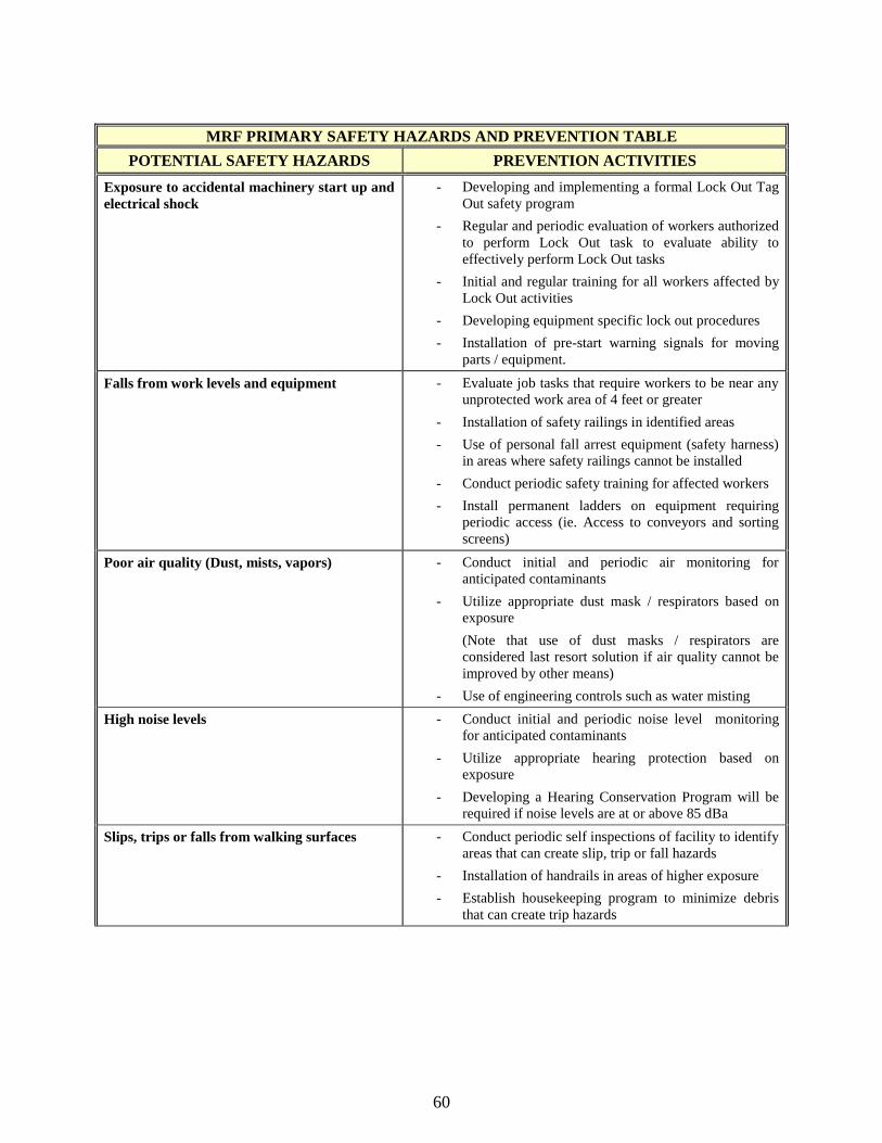
60
MRF PRIMARY SAFETY HAZARDS AND PREVENTION TABLE
POTENTIAL SAFETY HAZARDS PREVENTION ACTIVITIES
Exposure to accidental machinery start up and
electrical shock
- Developing and implementing a formal Lock Out Tag
Out safety program
- Regular and periodic evaluation of workers authorized
to perform Lock Out task to evaluate ability to
effectively perform Lock Out tasks
- Initial and regular training for all workers affected by
Lock Out activities
- Developing equipment specific lock out procedures
- Installation of pre-start warning signals for moving
parts / equipment.
Falls from work levels and equipment - Evaluate job tasks that require workers to be near any
unprotected work area of 4 feet or greater
- Installation of safety railings in identified areas
- Use of personal fall arrest equipment (safety harness)
in areas where safety railings cannot be installed
- Conduct periodic safety training for affected workers
- Install permanent ladders on equipment requiring
periodic access (ie. Access to conveyors and sorting
screens)
Poor air quality (Dust, mists, vapors) - Conduct initial and periodic air monitoring for
anticipated contaminants
- Utilize appropriate dust mask / respirators based on
exposure
(Note that use of dust masks / respirators are
considered last resort solution if air quality cannot be
improved by other means)
- Use of engineering controls such as water misting
High noise levels
- Conduct initial and periodic noise level monitoring
for anticipated contaminants
- Utilize appropriate hearing protection based on
exposure
- Developing a Hearing Conservation Program will be
required if noise levels are at or above 85 dBa
Slips, trips or falls from walking surfaces - Conduct periodic self inspections of facility to identify
areas that can create slip, trip or fall hazards
- Installation of handrails in areas of higher exposure
- Establish housekeeping program to minimize debris
that can create trip hazards
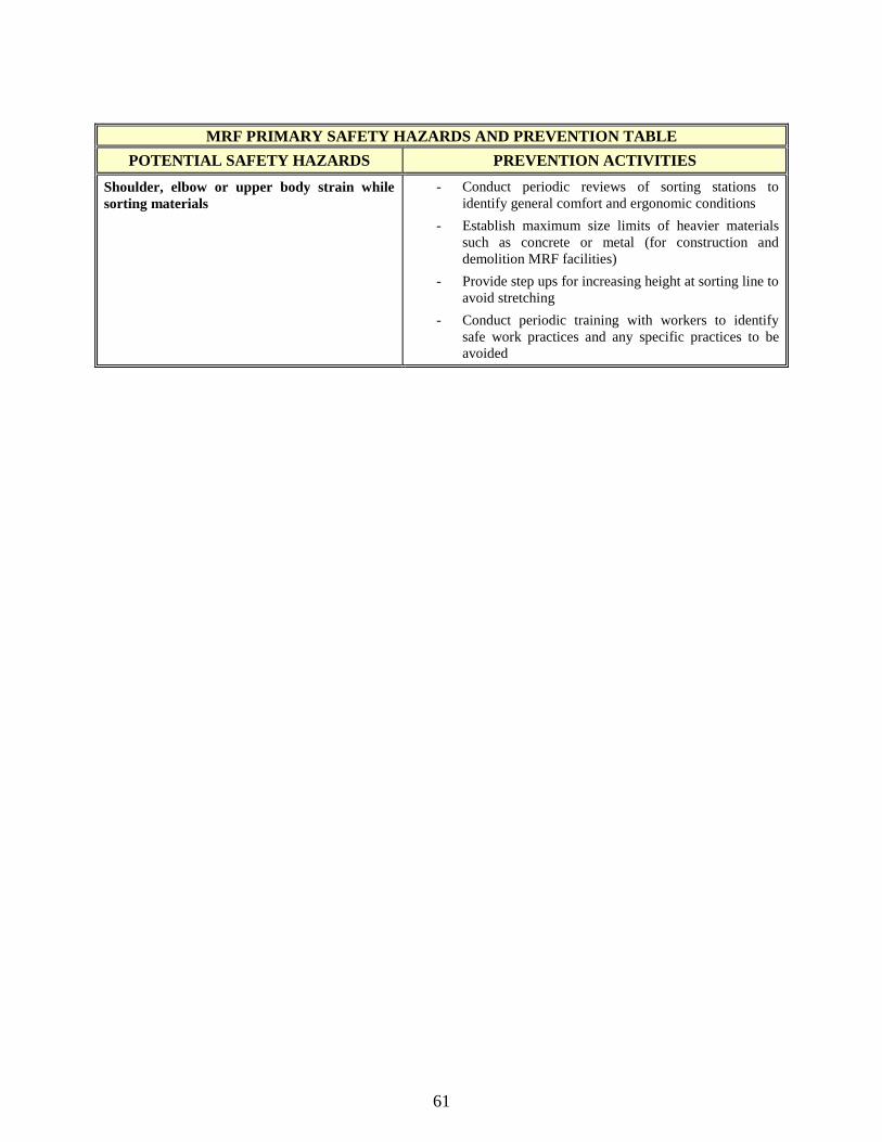
61
MRF PRIMARY SAFETY HAZARDS AND PREVENTION TABLE
POTENTIAL SAFETY HAZARDS PREVENTION ACTIVITIES
Shoulder, elbow or upper body strain while
sorting materials
- Conduct periodic reviews of sorting stations to
identify general comfort and ergonomic conditions
- Establish maximum size limits of heavier materials
such as concrete or metal (for construction and
demolition MRF facilities)
- Provide step ups for increasing height at sorting line to
avoid stretching
- Conduct periodic training with workers to identify
safe work practices and any specific practices to be
avoided
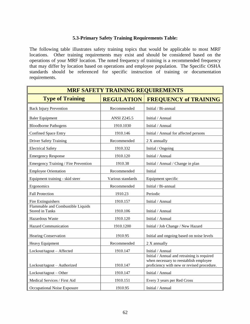
62
5.3-Primary Safety Training Requirements Table:
The following table illustrates safety training topics that would be applicable to most MRF
locations. Other training requirements may exist and should be considered based on the
operations of your MRF location. The noted frequency of training is a recommended frequency
that may differ by location based on operations and employee population. The Specific OSHA
standards should be referenced for specific instruction of training or documentation
requirements.
MRF SAFETY TRAINING REQUIREMENTS
Type of Training REGULATION FREQUENCY of TRAINING
Back Injury Prevention Recommended Initial / Bi-annual
Baler Equipment ANSI Z245.5 Initial / Annual
Bloodborne Pathogens 1910.1030 Initial / Annual
Confined Space Entry 1910.146 Initial / Annual for affected persons
Driver Safety Training Recommended 2 X annually
Electrical Safety 1910.332 Initial / Ongoing
Emergency Response 1910.120 Initial / Annual
Emergency Training / Fire Prevention 1910.38 Initial / Annual / Change in plan
Employee Orientation Recommended Initial
Equipment training - skid steer Various standards Equipment specific
Ergonomics Recommended Initial / Bi-annual
Fall Protection 1910.23 Periodic
Fire Extinguishers 1910.157 Initial / Annual
Flammable and Combustible Liquids
Stored in Tanks 1910.106 Initial / Annual
Hazardous Waste 1910.120 Initial / Annual
Hazard Communication 1910.1200 Initial / Job Change / New Hazard
Hearing Conservation 1910.95 Initial and ongoing based on noise levels
Heavy Equipment Recommended 2 X annually
Lockout/tagout – Affected 1910.147 Initial / Annual
Lockout/tagout – Authorized 1910.147
Initial / Annual and retraining is required
when necessary to reestablish employee
proficiency with new or revised procedure.
Lockout/tagout – Other 1910.147 Initial / Annual
Medical Services / First Aid 1910.151 Every 3 years per Red Cross
Occupational Noise Exposure 1910.95 Initial / Annual

63
Overhead Cranes 1910.179 Initial / Annual
MRF SAFETY TRAINING REQUIREMENTS
Type of Training REGULATION FREQUENCY of TRAINING
Personal Protective Equipment 1910.132 Initial use / change in work or PPE use
Powered Industrial Trucks 1910.178 Initial / Every 3 Years
Respiratory Protection 1910.134 Initial / Annual / New Hazard
Walking and working surfaces 1910 Subpart D Initial / Annual
Hotwork 1910.252
Initial / Annual- prior to the time of initial
assignment

64
5.4- Primary Safety Program Requirements Table: The following table illustrates safety program topics that would be applicable to most MRF
locations. Each MRF location should have written safety policies related to these issues. The
topics listed in this table are primarily related to injury prevention. Additional OSHA
requirements may exist. As each MRF location will differ, the specific need for other topics
would need to be assessed on a location specific basis. Note that many of these safety policies
would require related employee safety training.
MRF SAFETY PROGRAM REQUIREMENTS
Name of Program REGULATION
REQUIRED TOPICS
Bloodborne Pathogens 1910.1030
Electrical Safety 1910.332
Emergency Response 1910.120
Emergency Training / Fire Prevention 1910.38
Employee Orientation
Discipline / Enforcement 1910 cfr
Fall Protection 1910.23
Hearing Conservation 1910.95
Lockout/ Tagout 1910.147
Powered Industrial Trucks 1910.178
Personal Protective Equipment 1910.132
Respiratory Protection 1910.134
Confined Space Entry 1910.146
Lead 1910.1025
RECOMMENDED TOPICS
Discipline / Enforcement Recommended
Driver Safety Policies Recommended
General Safety Rules Recommended
Safety Policy Statement Recommended
Early Return to Work Recommended
Drug Free Work Place Recommended
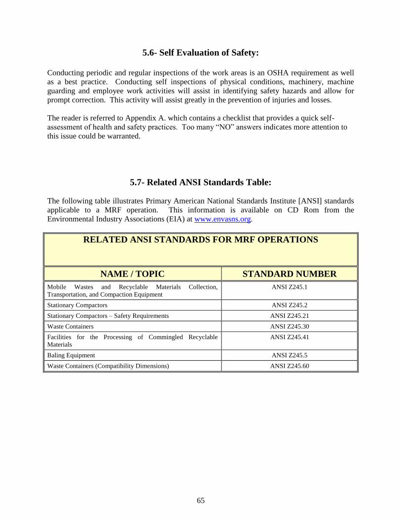
65
5.6- Self Evaluation of Safety:
Conducting periodic and regular inspections of the work areas is an OSHA requirement as well
as a best practice. Conducting self inspections of physical conditions, machinery, machine
guarding and employee work activities will assist in identifying safety hazards and allow for
prompt correction. This activity will assist greatly in the prevention of injuries and losses.
The reader is referred to Appendix A. which contains a checklist that provides a quick self-
assessment of health and safety practices. Too many ―NO‖ answers indicates more attention to
this issue could be warranted.
5.7- Related ANSI Standards Table: The following table illustrates Primary American National Standards Institute [ANSI] standards
applicable to a MRF operation. This information is available on CD Rom from the
Environmental Industry Associations (EIA) at www.envasns.org.
RELATED ANSI STANDARDS FOR MRF OPERATIONS
NAME / TOPIC STANDARD NUMBER
Mobile Wastes and Recyclable Materials Collection,
Transportation, and Compaction Equipment
ANSI Z245.1
Stationary Compactors ANSI Z245.2
Stationary Compactors – Safety Requirements ANSI Z245.21
Waste Containers ANSI Z245.30
Facilities for the Processing of Commingled Recyclable
Materials
ANSI Z245.41
Baling Equipment ANSI Z245.5
Waste Containers (Compatibility Dimensions) ANSI Z245.60

66
5.8- Safety References:
Various safety and health resources are available to MRF operators. Some useful resources are
listed below:
www.Osha.gov - The official OSHA website. A useful on line resource to access OSHA
standards, electronic tools, fatality statistics, letters of interpretation, etc.
www.Bls.gov- The official website for Bureau of Labor Statistics. A useful on line
resource to access labor statistics related to injury and severity rates. Can be used to
compare individual location safety results to national results.
www.Cdc.gov/niosh- The official website for National Institute of Occupational Health.
Contains much data for loss statistics, reference guide for chemical safety and many other
publications related to safety and health.
Environmental Industry Associations (EIA) ―Manual of Recommended Safety Practices‖
This manual addresses various safety issues in the solid waste and recycling industry
including specific information for MRF operations.
Environmental Industry Associations (EIA) - ANSI Z245 equipment safety requirements
CD Rom.
To obtain more information from EIA on the Manual of Recommended Safety Practices
and the, or to order a copy of the manual and/or the ANSI Z245 requirements, the EIA
can be contacted at 1-800-424-2869 or through their website at www.envasns.org. The
standards can also be purchased and downloaded on-line from the ANSI eStandards Store
at http://webstore.ansi.org/ansidocstore.
Illinois Department of Commerce and Economic Development‘s Onsite Safety and
Health Consultation Program:
This free onsite consultation program is designed to identify potential hazards and
recognize existing precautionary measures your company is already taking to keep your
workplace safe. Their services include providing onsite safety surveys, industrial
hygiene surveys, health and safety program audits, training and education, and
management program development and assistance. The consultants are state employees
and have no authority to issue citations or fines to employers for violations found or to
file reports to OSHA (except under extreme circumstances). More information on this

67
program may be obtained from their website at http://www.illinoisbiz.biz/osha/index.htm.
Check the resource list for downloadable copies of many useful manuals. The “Forklift
Safety Guide‖ is especially recommended.
―NIOSH Alert: Preventing Deaths and Injuries While Compacting or Baling Refuse
Material,‖ DHHS (NIOSH) Publication No. 2003-124. This publication is available from
1-800-35-NIOSH or from the NIOSH web page at http://www.cdc.gov/niosh/docs/2003-
124/ .

68
5.9- Photo Illustrations
The following photos provide specific comment on safety issues related to those operations.
PHOTOGRAPH 1.:
Hand sorting operations may require
additional safety attention to include
high visibility clothing, training on
ergonomics and possibly job
rotation.
PHOTOGRAPH 2.:
An example of safety signage
indicating required personal
protective equipment.
PHOTOGRAPH 3.:
Safe operation of heavy equipment
requires constant attention to avoid
contact with fixed objects and
minimizing personnel foot traffic.

69
PHOTOGRAPH 4.:
An illustration of labeling on an
electrical disconnect identifying the
affected equipment.
PHOTOGRAPH 5.:
An example of machine guarding.
Machine guarding should be a high
visibility color to communicate
potential hazards.
PHOTOGRAPH 6.:
Fire extinguishers should be located
throughout the facility with clear
access paths maintained.
The proper type of fire extinguisher
should be evaluated based on fire
exposures.

70
PHOTOGRAPH 7.:
An example of appropriate safety
and hand railings on an access stair
way.
High visibility colors for safety
equipment is recommended and
required in certain applications.
PHOTOGRAPH 8.:
An example of an elevated work
platform. Work platforms must be
safe to work from and should contain
no holes that can lead to tripping.
Work platforms must also be sturdy
and not subject to tipping over.
PHOTOGRAPH 9.:
All personnel that may walk in areas
where heavy equipment is in
operation are required to wear high
visibility clothing.

71
PHOTOGRAPH 10.:
Only trained and authorized
personnel may operate forklift
trucks.
Training is required initially and at
least every 3 years.
PHOTOGRAPH 11.:
Other equipment that is used in a
MRF location will require
appropriate safety training for
affected employees.
PHOTOGRAPH 12.:
An example of a lock out procedure
utilizing multiple locks.
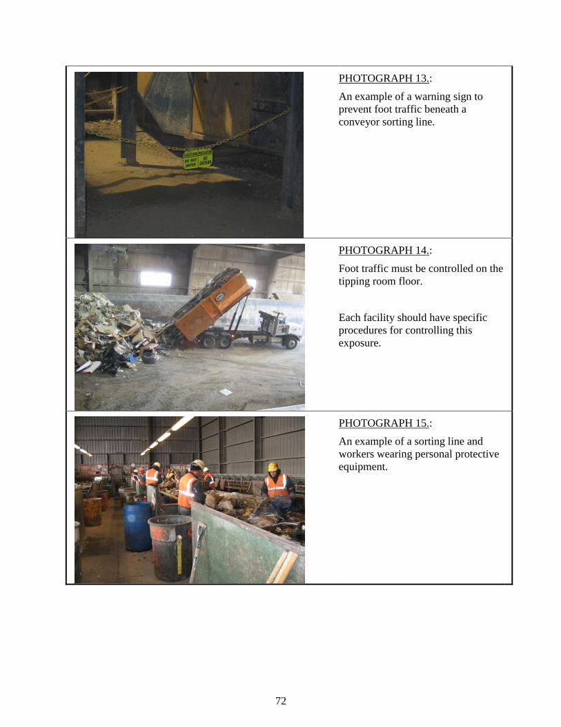
72
PHOTOGRAPH 13.:
An example of a warning sign to
prevent foot traffic beneath a
conveyor sorting line.
PHOTOGRAPH 14.:
Foot traffic must be controlled on the
tipping room floor.
Each facility should have specific
procedures for controlling this
exposure.
PHOTOGRAPH 15.:
An example of a sorting line and
workers wearing personal protective
equipment.
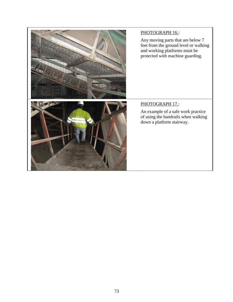
73
PHOTOGRAPH 16.:
Any moving parts that are below 7
feet from the ground level or walking
and working platforms must be
protected with machine guarding.
PHOTOGRAPH 17.:
An example of a safe work practice
of using the handrails when walking
down a platform stairway.
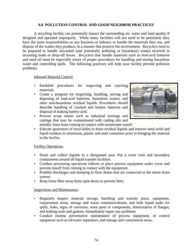
74
6.0 POLLUTION CONTROL AND GOOD NEIGHBOR PRACTICES
A recycling facility can potentially impact the surrounding air, water and land quality if
designed and operated improperly. While many facilities will not need to be permitted, they
have the same responsibilities as any business or industry to handle the materials they use, and
dispose of the wastes they produce, in a manner that protects the environment. Recyclers need to
be prepared to handle unwanted (and potentially polluting or hazardous) wastes received in
incoming loads or drop-off boxes. Recyclers that handle materials such as lead-acid batteries
and used oil must be especially aware of proper procedures for handling and storing hazardous
waste and controlling spills. The following practices will help your facility prevent pollution
problems.
Inbound Material Control.
• Establish procedures for inspecting and rejecting
materials.
• Create a program for inspecting, handling, storing and
disposing of lead-acid batteries, hazardous wastes, and
other non-hazardous residual liquids. Procedures should
describe handling of cracked and broken batteries and
disposal of leaking battery acid.
• Prevent scrap metals such as industrial turnings and
cuttings that may be contaminated with cutting oils and
metallic fines from coming in contact with stormwater runoff.
• Educate generators of recyclables to drain residual liquids and remove semi-solid and
liquid residues in aluminum, plastic and steel containers prior to bringing the material
to the facility.
Facility Operations.
• Drain and collect liquids in a designated area. Put a cover over and secondary
containment around all liquid transfer facilities.
• Conduct processing operations indoors or place process equipment under cover and
prevent runoff from coming in contact with the equipment.
• Prohibit discharges and dumping to floor drains that are connected to the storm drain
system.
• Keep loose fiber away from open doors to prevent litter.
Inspections and Maintenance.
• Regularly inspect material storage, handling and transfer areas, equipment,
containment areas, storage and waste containers/drums, and bulk liquid tanks for
spills, leaks, signs of corrosion, worn parts or components, deterioration of flanges,
and leaking seals and gaskets. Immediately repair any problems
• Conduct routine preventative maintenance of process equipment, of control
equipment such as oil/water separators, and storage and containment areas.

75
• Conduct periodic nondestructive testing of all bulk storage tanks for signs of
deteriorating structural integrity.
Spills and Facility Clean-up.
• Establish spill prevention and response procedures and use dry methods to clean up
spills. Keep an adequate supply of dry clean up materials readily accessible.
• Schedule frequent cleaning of accumulated fluids and particulate residue around all
processing equipment, storage containers and high traffic areas.
• Regularly sweep all traffic and storage areas to minimize particulate and residual
materials buildup.
• Prohibit washing down of material storage and tipping floor areas, unless a
washwater collection system is in place or approval is granted by the wastewater
treatment plant to discharge wash waters to the sanitary sewer
Material Storage.
• Store all materials and waste indoors or in covered areas with curbing, berms or other
containment measures.
• Surfaces of secondary containment areas should be adequately sealed to prevent
leaks.
• Separate all scrap batteries from other scrap materials and segregate hazardous and
flammable wastes to comply with National Fire Protection Association (NFPA)
guidelines.
• Store materials in appropriate containers near the point of use or production of the
materials (i.e. shredded materials and fluff).
• Make sure that all storage containers and drums are in good condition and meet
NFPA guidelines.
• Clearly label all containers and include necessary warnings and special handling
instructions
• In the storage areas, put individual containers on pallets. Limit the stack height of
individual containers/drums and put straps or plastic wrap around the drums to
provide stability.
• Provide adequate clearance to allow material movement and access by material
handling equipment.
Waste Disposal.
• Segregate any potentially hazardous wastes or residues from non-hazardous wastes.
• Make a determination of your hazardous waste generator category and follow state
regulations for your category:
- CESQG‘s: Conditionally Exempt Small Quantity Generators accumulate less than
220 pounds per month of hazardous waste and less than 2.2 pounds of acutely
hazardous waste.

76
- SQG‘s: Small Quantity Generators accumulate less than 2200 pounds per month
of hazardous waste.
- LQG‘s: Large Quantity Generators accumulate more than 2200 pounds per month
of hazardous waste.
More information on managing special wastes may be found on the Illinois EPA‘s
website at: http://www.epa.state.il.us/land/waste-mgmt/special-waste.html.
Most common citizens‘ concerns about recycling facilities include noise, odor, traffic,
dust, vectors, litter, and aesthetics. Other concerns include water pollution, fire concerns and
hazardous waste.
The issues of noise, litter and odor should be addressed during the design and operations
plan. Noise and litter can be controlled or minimized by fully
enclosing the receiving and processing areas and requiring all vehicles
to tarp their trucks. Vector control may require periodic professional
treatment but many facilities find natural, organic controls effective.
Odor control chemicals that react with and neutralize odors should be
considered, as well as utilizing a negative air pressure system inside the
building. If necessary, exhaust air can be treated using activated carbon
filters prior to being exhausted into the atmosphere.
Dust is created from tipping and loading operations. Misting and using air handling and
filtering equipment can control dust. If necessary, dust collection ducts with filter or baghouse
installations can be installed over the tipping floor and processing equipment to collect airborne
particulate matter. Prevention techniques are generally less costly than treatment and
remediation. Table 6.0 lists common concerns and mitigation measures.
TABLE 6.0. POTENTIAL IMPACTS ON NEIGHBORS AND MITIGATION MEASURES
Concerns Mitigation Design Features Mitigation Operational Procedures Aesthetics • Setback distances/buffer zones
• Landscaping and man-made screens
• Building exterior
• Fencing
• Keep entrance and visible areas clean
• Maintain building exterior
• Maintain building and grounds
Fire • Automatic sprinkler systems
• Fire extinguishers at key locations
• Area for hot load segregation
• Plan approval by local fire department
• Employee training
• Load inspections
Odor • Orient building considering predominant
wind direction
• Setback distances, greater in direction of
prevailing winds
• Exhaust fans with air filters
• Mist system to treat odors
• Automatic door operators
• Immediate handling of odorous loads
• Processing inside building only
• Load tarping requirements
• Removal of all residuals by end of day
• Site road and tipping floor cleaning
• Operate exhaust system during operating
hours
Dust and Mud • Automatic misting system
• Building orientation with respect to
predominant wind direction
• Paved access roads
• Daily sweep of roads
• Wet roads as required
• Process materials inside building
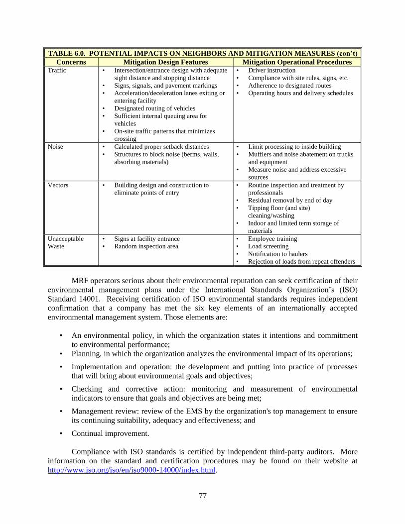
77
TABLE 6.0. POTENTIAL IMPACTS ON NEIGHBORS AND MITIGATION MEASURES (con’t) Concerns Mitigation Design Features Mitigation Operational Procedures
Traffic • Intersection/entrance design with adequate
sight distance and stopping distance
• Signs, signals, and pavement markings
• Acceleration/deceleration lanes exiting or
entering facility
• Designated routing of vehicles
• Sufficient internal queuing area for
vehicles
• On-site traffic patterns that minimizes
crossing
• Driver instruction
• Compliance with site rules, signs, etc.
• Adherence to designated routes
• Operating hours and delivery schedules
Noise • Calculated proper setback distances
• Structures to block noise (berms, walls,
absorbing materials)
• Limit processing to inside building
• Mufflers and noise abatement on trucks
and equipment
• Measure noise and address excessive
sources
Vectors • Building design and construction to
eliminate points of entry
• Routine inspection and treatment by
professionals
• Residual removal by end of day
• Tipping floor (and site)
cleaning/washing
• Indoor and limited term storage of
materials
Unacceptable
Waste
• Signs at facility entrance
• Random inspection area
• Employee training
• Load screening
• Notification to haulers
• Rejection of loads from repeat offenders
MRF operators serious about their environmental reputation can seek certification of their
environmental management plans under the International Standards Organization‘s (ISO)
Standard 14001. Receiving certification of ISO environmental standards requires independent
confirmation that a company has met the six key elements of an internationally accepted
environmental management system. Those elements are:
• An environmental policy, in which the organization states it intentions and commitment
to environmental performance;
• Planning, in which the organization analyzes the environmental impact of its operations;
• Implementation and operation: the development and putting into practice of processes
that will bring about environmental goals and objectives;
• Checking and corrective action: monitoring and measurement of environmental
indicators to ensure that goals and objectives are being met;
• Management review: review of the EMS by the organization's top management to ensure
its continuing suitability, adequacy and effectiveness; and
• Continual improvement.
Compliance with ISO standards is certified by independent third-party auditors. More
information on the standard and certification procedures may be found on their website at
http://www.iso.org/iso/en/iso9000-14000/index.html.
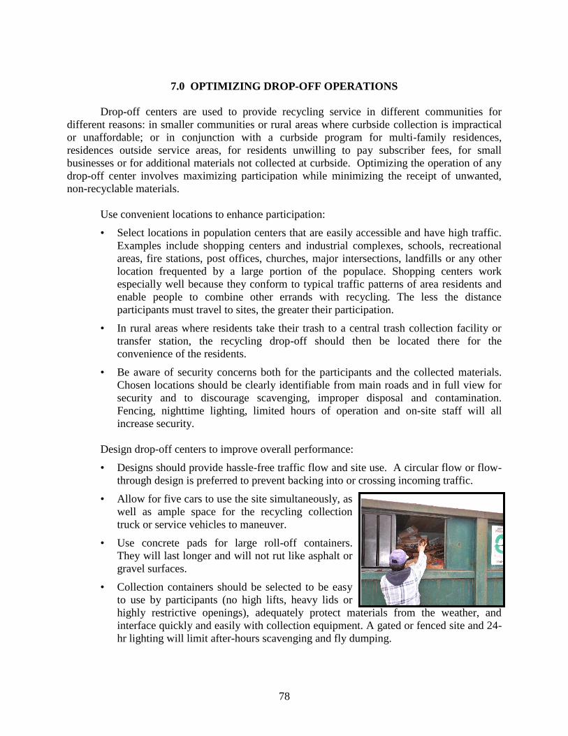
78
7.0 OPTIMIZING DROP-OFF OPERATIONS
Drop-off centers are used to provide recycling service in different communities for
different reasons: in smaller communities or rural areas where curbside collection is impractical
or unaffordable; or in conjunction with a curbside program for multi-family residences,
residences outside service areas, for residents unwilling to pay subscriber fees, for small
businesses or for additional materials not collected at curbside. Optimizing the operation of any
drop-off center involves maximizing participation while minimizing the receipt of unwanted,
non-recyclable materials.
Use convenient locations to enhance participation:
• Select locations in population centers that are easily accessible and have high traffic.
Examples include shopping centers and industrial complexes, schools, recreational
areas, fire stations, post offices, churches, major intersections, landfills or any other
location frequented by a large portion of the populace. Shopping centers work
especially well because they conform to typical traffic patterns of area residents and
enable people to combine other errands with recycling. The less the distance
participants must travel to sites, the greater their participation.
• In rural areas where residents take their trash to a central trash collection facility or
transfer station, the recycling drop-off should then be located there for the
convenience of the residents.
• Be aware of security concerns both for the participants and the collected materials.
Chosen locations should be clearly identifiable from main roads and in full view for
security and to discourage scavenging, improper disposal and contamination.
Fencing, nighttime lighting, limited hours of operation and on-site staff will all
increase security.
Design drop-off centers to improve overall performance:
• Designs should provide hassle-free traffic flow and site use. A circular flow or flow-
through design is preferred to prevent backing into or crossing incoming traffic.
• Allow for five cars to use the site simultaneously, as
well as ample space for the recycling collection
truck or service vehicles to maneuver.
• Use concrete pads for large roll-off containers.
They will last longer and will not rut like asphalt or
gravel surfaces.
• Collection containers should be selected to be easy
to use by participants (no high lifts, heavy lids or
highly restrictive openings), adequately protect materials from the weather, and
interface quickly and easily with collection equipment. A gated or fenced site and 24-
hr lighting will limit after-hours scavenging and fly dumping.

79
Accept as many materials as possible at one site to increase recovery:
• A one-stop-drop is preferable to taking different materials to different locations and
will increase participation.
• Consider including or partnering with swap shop or reuse operations to allow
collection of reusable items.
• Periodic drives or special collection events can collect products with unstable
markets, such as mixed paper, or with seasonal disposal patterns, such as telephone
books or Christmas wrap.
Maintain a clean and attractive site:
• Maintain adequate collection and storage space and provide reliable service and
pickup of materials at the drop-off stations. Overflowing and dirty recycling bins are
unsightly and negatively affect participation and neighborhood acceptance.
• Well-drained and paved surfaces
are preferred. No one likes
tramping through mud and water
to get to drop-off containers.
• Provide a trash can for
unacceptable items and
incidental waste and to help
reduce litter. This trashcan is
vital to help reduce contaminants. Plastic bags used to bring the recyclables to the
site are the most common contaminant. If a trash can is not there for these materials,
people may put them in recycling bins rather than carry them back home. It may cost
to dispose of this trash but losing markets to excess contamination, or having to sort it
out then dispose of it anyway, will cost more. Inspect the site frequently and remove
any litter or dumped trash promptly. Also repair or remove vandalism promptly.
• Consider landscaping for a more attractive site. Flowerbeds could feature locally
produced compost.
Provide education to the user both before and after they arrive at the site.
• Distribute informational material to the target communities so people are thoroughly
familiar with the specific recyclables wanted before they arrive at the site, or they
may deposit unacceptable materials just to avoid taking them back home for disposal.
Ensure that the educational material lists acceptable items, drop-off locations,
preparation instructions, time and day when the drop-off site is open, and who to
contact with questions. Simple, active language and simple line graphics in the
printed material is very important.
• To get the information out about the recycling program, use radio and TV spots,
newspaper ads and articles, and billboard ads; visit and give presentations to
neighborhood associations, schools, churches and civic organizations to promote and
explain the program; put quarterly flyers, leaflets and/or newsletters in the
water/sewer bill, bank statement or by separate mailing by the water/sewer

80
department; train community volunteers on the program so they educate neighbors
and others; produce a video on local waste management/recycling program and
provide video free to video stores and setup a
display information booth on weekends at the
local malls, discount stores and/or food
centers.
• On-site, use highly visible signage to direct
traffic and label collection containers with
their desired contents. Clear signage is
important. Instructions on the recycling bins
should be attractive, simple and well marked to identify materials acceptable for the
containers. Large signs and large lettering are suggested. Signs at eye-level are more
frequently read than signs above or below. Avoid using technical jargon. Instead,
specify exactly what materials are accepted. ―Baiting‖ containers with appropriate
materials helps users know the material that goes in each bin. Where standardized
containers are used and swapped out, magnetic signs can be used and transferred to
new, empty containers.
Some of the underlying causes of high contamination include 1) people
frequently misinterpret the signs because the wording is unclear, 2) people
place unacceptable materials in the recyclables bin because no disposal
container was available, and 3) people find heavy container lids awkward to
hold open while attempting to place individual bottles and containers inside
so it is easier to toss the whole bundle in along with the bag or box. Some operators suggest that
collection containers should have restrictive openings to limit which items can go in. Others
note that users often object to the time it takes to feed items in one at a time and would rather
dump full bags or boxes into a large opening. The latter approach risks additional contamination
unless the users are well informed to dump only the recyclables and not to include the bags or
boxes as appropriate.
One of the most significant decisions in operating a recycling drop-off is whether to staff
it or not. Many sites operate adequately without staffing but are frequently subject to high
contamination levels and fly dumping. If a site has a limited operating schedule (Wednesdays,
Saturdays), then staffing is less of a challenge. A staffed site has less contamination than an un-
staffed site. On-site staff adds costs but also provides better control and service opportunities,
such as:
• Educating citizens on the items to recycle, the proper ways to do it, and the importance of
waste reduction and reuse. They can hand out literature, answer questions, and provide
information on ways to reduce wastes; for example, to compost food scraps, yard waste,
and other organic materials.
• Controlling litter, maintaining the site and preventing scavenging and excess
contamination/dumping.
• Assisting users with unloading vehicles.
• Operating compactors or other special equipment.
81
• Tracking participation data.
• Checking addresses if facility use is restricted to community residents.
• Operating swap shop, reuse exchanges or special collection events.
Whether the staff is paid or volunteer, ensure the staff is well trained in the specifics of
what is accepted and not accepted. Consider creating a site manual with this information in
detail, answers to users frequently asked questions, and other operational procedures.
If a site is open 24 hours, or for other reasons cannot be continuously staffed, monitor the
traffic at the site and provide staff during the periods of peak usage.

82
8.0 CONCLUSION
This manual identifies a number of ways that MRFs can improve operational efficiencies.
Not all concepts and practices listed in this guide will be applicable to all MRFs though MRFs
will find some useful information in the concepts and practices discussed. Additionally it should
be noted that the information presented in this guide are by no means the only methods MRFs
can use to optimize their operations.
Each MRF has unique conditions associated with quantities and types of materials
accepted and processed, the design/layout of the MRF, the type of sorting and processing
methods used, and the end markets. There‘s little doubt that other methods for improving
efficiencies can be identified in assessing operations in a specific MRF. Based on the experience
of the MRFs participating in this study there were a number of common operational areas that
were targets for efficiency improvements. These areas included:
• Materials Receiving: Provide adequate space for unloading materials from collection
vehicles. Move unloaded materials to processing or incoming materials storage as quickly
and safely as possible while minimizing cross-traffic with other operations. Flow of
materials through the MRF should proceed in fashion that minimizes backtracking or
multiple handling of materials.
• Materials Sorting: In small MRFs that are not heavily mechanized the efficient use of
labor is critical in the overall sorting operation. Provide training to all sorters. Adjust
transfer conveyors, sorting line conveyors, and other related equipment so that materials
to be sorted are easy to see and sort. Find the optimum conveyor speeds to control burden
depth and maximize sorting efficiencies. When it‘s economical to do so, add automation
to the sorting procedures (e.g. screens and magnets) as a way to reduce labor costs.
• Materials Processing: The types and quantities of materials to be processed along with
the materials specifications will determine the type and size of the processing equipment
needed. High quality equipment that can meet the product specifications is a must.
Undersized, underpowered equipment will add to overall operating costs such as labor
and energy usage. Oversized equipment may lead to that equipment being idle much of
the time and has initial costs higher than necessary. Match the equipment to the quantities
and flow of materials so it is in use much of the time but still has the capacity to meet
peak flows when needed.
• Product Storage: Provide efficient procedures for moving finished product to storage and
stored product into trailers or other containers for delivery to markets. Adequate indoor
storage space should be available to keep products susceptible to degradation from
exposure to the elements, dirt, and other contaminants. Adequate storage space should
also be available to ensure full loads of materials are available for shipment to markets as
well as to riding out poor short-term market conditions.

83
• Product Marketing: Viable, long-term markets should be available for all materials
recovered. Ensure that market contracts are structured to provide a fair price for all
commodities and protection against falling prices (i.e., floor price received for materials,
ability to wait out market conditions without being penalized for not shipping in a given
month, etc.). If quantities are large enough, diversify markets to allow flexibility in
marketing materials. This can be accomplished a number of ways including contracts
with multiple markets, moving materials through a broker, or participating with others in
cooperative marketing efforts.
• Health and Safety Considerations: Make health and safety considerations an overriding
issue in MRF operations. Provide the necessary health and safety training to all
employees as well as the appropriate personal protective equipment. Operating a MRF
with health and safety in mind will help control costs associated with workers
compensation claims, rising insurance rates, lost productivity, and regulatory/legal issues.
• Environmental Responsibility: In an industry that sells itself as being good for the
environment, it is especially important that the public not perceive recycling facilities as
an environmental nuisance. Make your best effort to maintain a neat and clean operation.
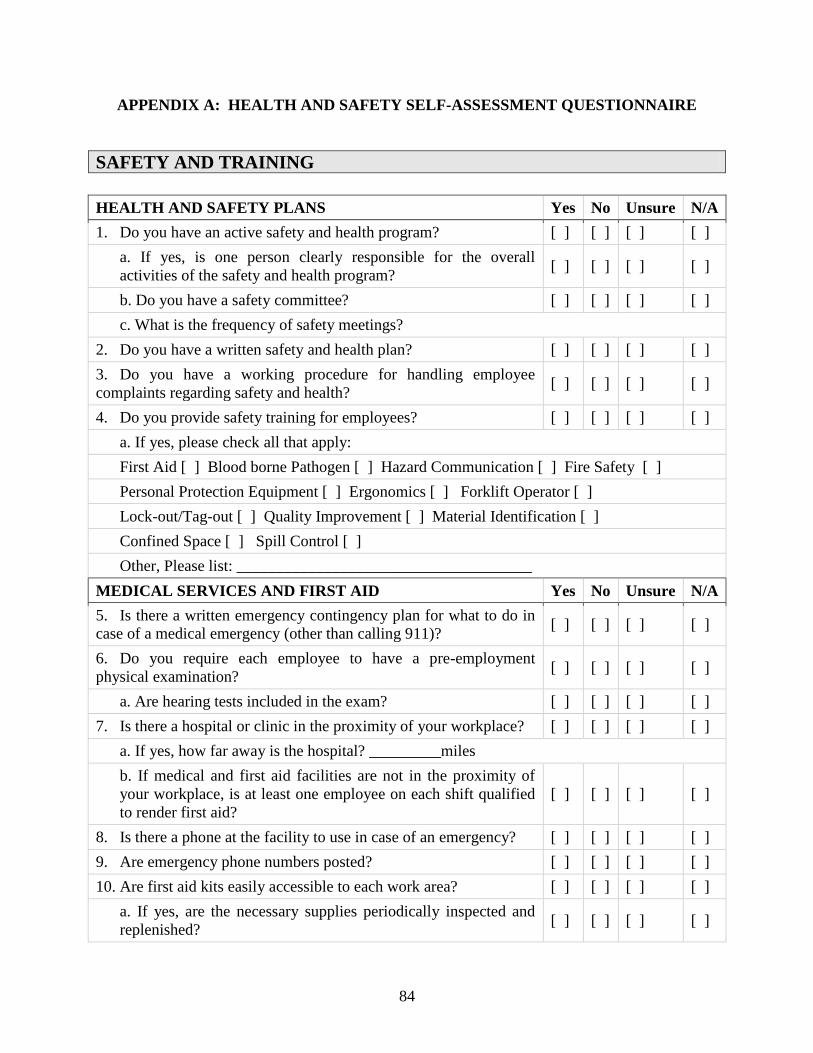
84
APPENDIX A: HEALTH AND SAFETY SELF-ASSESSMENT QUESTIONNAIRE
SAFETY AND TRAINING
HEALTH AND SAFETY PLANS Yes No Unsure N/A
1. Do you have an active safety and health program? [ ] [ ] [ ] [ ]
a. If yes, is one person clearly responsible for the overall
activities of the safety and health program? [ ] [ ] [ ] [ ]
b. Do you have a safety committee? [ ] [ ] [ ] [ ]
c. What is the frequency of safety meetings?
2. Do you have a written safety and health plan? [ ] [ ] [ ] [ ]
3. Do you have a working procedure for handling employee
complaints regarding safety and health? [ ] [ ] [ ] [ ]
4. Do you provide safety training for employees? [ ] [ ] [ ] [ ]
a. If yes, please check all that apply:
First Aid [ ] Blood borne Pathogen [ ] Hazard Communication [ ] Fire Safety [ ]
Personal Protection Equipment [ ] Ergonomics [ ] Forklift Operator [ ]
Lock-out/Tag-out [ ] Quality Improvement [ ] Material Identification [ ]
Confined Space [ ] Spill Control [ ]
Other, Please list: _____________________________________
MEDICAL SERVICES AND FIRST AID Yes No Unsure N/A
5. Is there a written emergency contingency plan for what to do in
case of a medical emergency (other than calling 911)? [ ] [ ] [ ] [ ]
6. Do you require each employee to have a pre-employment
physical examination? [ ] [ ] [ ] [ ]
a. Are hearing tests included in the exam? [ ] [ ] [ ] [ ]
7. Is there a hospital or clinic in the proximity of your workplace? [ ] [ ] [ ] [ ]
a. If yes, how far away is the hospital? _________miles
b. If medical and first aid facilities are not in the proximity of
your workplace, is at least one employee on each shift qualified
to render first aid?
[ ] [ ] [ ] [ ]
8. Is there a phone at the facility to use in case of an emergency? [ ] [ ] [ ] [ ]
9. Are emergency phone numbers posted? [ ] [ ] [ ] [ ]
10. Are first aid kits easily accessible to each work area? [ ] [ ] [ ] [ ]
a. If yes, are the necessary supplies periodically inspected and
replenished? [ ] [ ] [ ] [ ]

85
11. Are means provided for flushing the eyes in the area where
materials are being handled that may injure the eyes? [ ] [ ] [ ] [ ]
12. Are employees CPR trained? [ ] [ ] [ ] [ ]
FIRE PROTECTION Yes No Unsure N/A
13. Does your facility have a fire alarm system? [ ] [ ] [ ] [ ]
a. If yes, is it tested annually? [ ] [ ] [ ] [ ]
14. Does your facility have an automatic sprinkler system? [ ] [ ] [ ] [ ]
a. If yes, are automatic sprinkler system water control valves, air
and water pressure checked weekly or periodically? [ ] [ ] [ ] [ ]
15. Are portable fire extinguishers provided? [ ] [ ] [ ] [ ]
a. If yes, how many are there? #_____________
b. Are all extinguishers serviced, maintained and tagged at
intervals not to exceed one year? [ ] [ ] [ ] [ ]
c. Are employees periodically instructed in the use of
extinguishers and fire protection procedures? [ ] [ ] [ ] [ ]
d. If yes, how often?
GENERAL WORK ENVIRONMENT Yes No Unsure N/A
16. Are all work sites clean and orderly? [ ] [ ] [ ] [ ]
17. Are work surfaces kept dry or are appropriate means taken to
assure the surfaces are slip-resistant? [ ] [ ] [ ] [ ]
18. Are all spilled materials or liquids cleaned up immediately? [ ] [ ] [ ] [ ]
19. Are covered metal waste cans used for oily waste? [ ] [ ] [ ] [ ]
20. Are all toilets and washing facilities clean and sanitary? [ ] [ ] [ ] [ ]
21. Are all work areas adequately illuminated? [ ] [ ] [ ] [ ]
22. Are pits and floor openings covered or otherwise guarded? [ ] [ ] [ ] [ ]
23. Is there a public drop off area for materials? [ ] [ ] [ ] [ ]
a. If yes, does the drop off area present any noticeable safety concerns for the public. List
concerns:
ENVIRONMENTAL CONTROLS Yes No Unsure N/A
24. Is all water provided for drinking and washing potable? [ ] [ ] [ ] [ ]
25. Are all outlets for water not suitable for drinking clearly
identified? [ ] [ ] [ ] [ ]
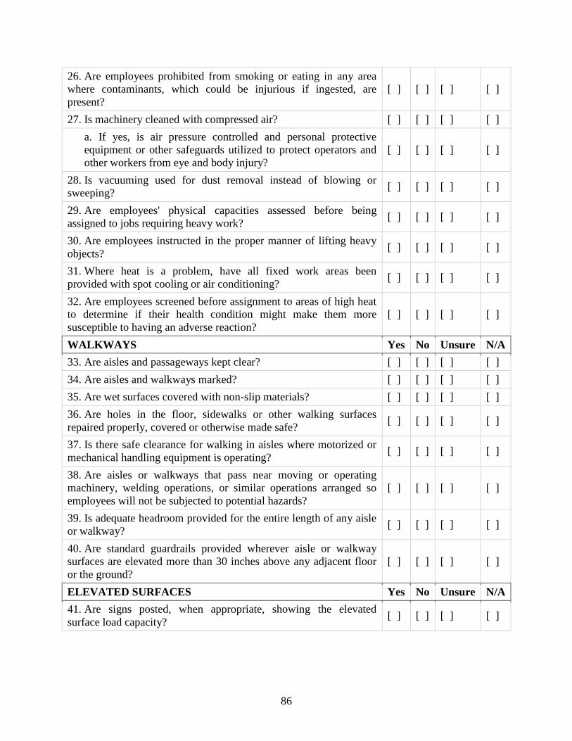
86
26. Are employees prohibited from smoking or eating in any area
where contaminants, which could be injurious if ingested, are
present?
[ ] [ ] [ ] [ ]
27. Is machinery cleaned with compressed air? [ ] [ ] [ ] [ ]
a. If yes, is air pressure controlled and personal protective
equipment or other safeguards utilized to protect operators and
other workers from eye and body injury?
[ ] [ ] [ ] [ ]
28. Is vacuuming used for dust removal instead of blowing or
sweeping? [ ] [ ] [ ] [ ]
29. Are employees' physical capacities assessed before being
assigned to jobs requiring heavy work? [ ] [ ] [ ] [ ]
30. Are employees instructed in the proper manner of lifting heavy
objects? [ ] [ ] [ ] [ ]
31. Where heat is a problem, have all fixed work areas been
provided with spot cooling or air conditioning? [ ] [ ] [ ] [ ]
32. Are employees screened before assignment to areas of high heat
to determine if their health condition might make them more
susceptible to having an adverse reaction?
[ ] [ ] [ ] [ ]
WALKWAYS Yes No Unsure N/A
33. Are aisles and passageways kept clear? [ ] [ ] [ ] [ ]
34. Are aisles and walkways marked? [ ] [ ] [ ] [ ]
35. Are wet surfaces covered with non-slip materials? [ ] [ ] [ ] [ ]
36. Are holes in the floor, sidewalks or other walking surfaces
repaired properly, covered or otherwise made safe? [ ] [ ] [ ] [ ]
37. Is there safe clearance for walking in aisles where motorized or
mechanical handling equipment is operating? [ ] [ ] [ ] [ ]
38. Are aisles or walkways that pass near moving or operating
machinery, welding operations, or similar operations arranged so
employees will not be subjected to potential hazards?
[ ] [ ] [ ] [ ]
39. Is adequate headroom provided for the entire length of any aisle
or walkway? [ ] [ ] [ ] [ ]
40. Are standard guardrails provided wherever aisle or walkway
surfaces are elevated more than 30 inches above any adjacent floor
or the ground?
[ ] [ ] [ ] [ ]
ELEVATED SURFACES Yes No Unsure N/A
41. Are signs posted, when appropriate, showing the elevated
surface load capacity? [ ] [ ] [ ] [ ]
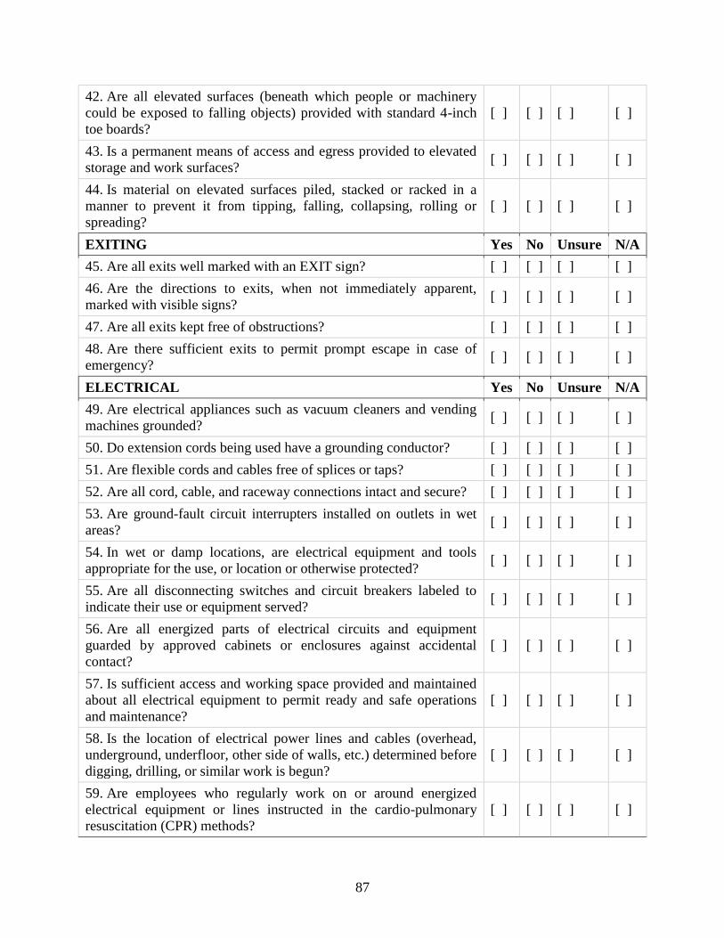
87
42. Are all elevated surfaces (beneath which people or machinery
could be exposed to falling objects) provided with standard 4-inch
toe boards?
[ ] [ ] [ ] [ ]
43. Is a permanent means of access and egress provided to elevated
storage and work surfaces? [ ] [ ] [ ] [ ]
44. Is material on elevated surfaces piled, stacked or racked in a
manner to prevent it from tipping, falling, collapsing, rolling or
spreading?
[ ] [ ] [ ] [ ]
EXITING Yes No Unsure N/A
45. Are all exits well marked with an EXIT sign? [ ] [ ] [ ] [ ]
46. Are the directions to exits, when not immediately apparent,
marked with visible signs? [ ] [ ] [ ] [ ]
47. Are all exits kept free of obstructions? [ ] [ ] [ ] [ ]
48. Are there sufficient exits to permit prompt escape in case of
emergency? [ ] [ ] [ ] [ ]
ELECTRICAL Yes No Unsure N/A
49. Are electrical appliances such as vacuum cleaners and vending
machines grounded? [ ] [ ] [ ] [ ]
50. Do extension cords being used have a grounding conductor? [ ] [ ] [ ] [ ]
51. Are flexible cords and cables free of splices or taps? [ ] [ ] [ ] [ ]
52. Are all cord, cable, and raceway connections intact and secure? [ ] [ ] [ ] [ ]
53. Are ground-fault circuit interrupters installed on outlets in wet
areas? [ ] [ ] [ ] [ ]
54. In wet or damp locations, are electrical equipment and tools
appropriate for the use, or location or otherwise protected? [ ] [ ] [ ] [ ]
55. Are all disconnecting switches and circuit breakers labeled to
indicate their use or equipment served? [ ] [ ] [ ] [ ]
56. Are all energized parts of electrical circuits and equipment
guarded by approved cabinets or enclosures against accidental
contact?
[ ] [ ] [ ] [ ]
57. Is sufficient access and working space provided and maintained
about all electrical equipment to permit ready and safe operations
and maintenance?
[ ] [ ] [ ] [ ]
58. Is the location of electrical power lines and cables (overhead,
underground, underfloor, other side of walls, etc.) determined before
digging, drilling, or similar work is begun?
[ ] [ ] [ ] [ ]
59. Are employees who regularly work on or around energized
electrical equipment or lines instructed in the cardio-pulmonary
resuscitation (CPR) methods?
[ ] [ ] [ ] [ ]
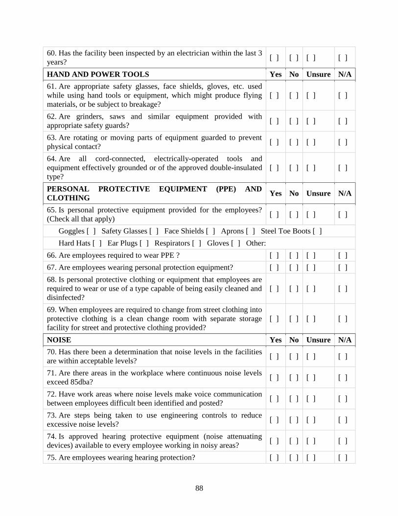
88
60. Has the facility been inspected by an electrician within the last 3
years? [ ] [ ] [ ] [ ]
HAND AND POWER TOOLS Yes No Unsure N/A
61. Are appropriate safety glasses, face shields, gloves, etc. used
while using hand tools or equipment, which might produce flying
materials, or be subject to breakage?
[ ] [ ] [ ] [ ]
62. Are grinders, saws and similar equipment provided with
appropriate safety guards? [ ] [ ] [ ] [ ]
63. Are rotating or moving parts of equipment guarded to prevent
physical contact? [ ] [ ] [ ] [ ]
64. Are all cord-connected, electrically-operated tools and
equipment effectively grounded or of the approved double-insulated
type?
[ ] [ ] [ ] [ ]
PERSONAL PROTECTIVE EQUIPMENT (PPE) AND
CLOTHING Yes No Unsure N/A
65. Is personal protective equipment provided for the employees?
(Check all that apply) [ ] [ ] [ ] [ ]
Goggles [ ] Safety Glasses [ ] Face Shields [ ] Aprons [ ] Steel Toe Boots [ ]
Hard Hats [ ] Ear Plugs [ ] Respirators [ ] Gloves [ ] Other:
66. Are employees required to wear PPE ? [ ] [ ] [ ] [ ]
67. Are employees wearing personal protection equipment? [ ] [ ] [ ] [ ]
68. Is personal protective clothing or equipment that employees are
required to wear or use of a type capable of being easily cleaned and
disinfected?
[ ] [ ] [ ] [ ]
69. When employees are required to change from street clothing into
protective clothing is a clean change room with separate storage
facility for street and protective clothing provided?
[ ] [ ] [ ] [ ]
NOISE Yes No Unsure N/A
70. Has there been a determination that noise levels in the facilities
are within acceptable levels? [ ] [ ] [ ] [ ]
71. Are there areas in the workplace where continuous noise levels
exceed 85dba? [ ] [ ] [ ] [ ]
72. Have work areas where noise levels make voice communication
between employees difficult been identified and posted? [ ] [ ] [ ] [ ]
73. Are steps being taken to use engineering controls to reduce
excessive noise levels? [ ] [ ] [ ] [ ]
74. Is approved hearing protective equipment (noise attenuating
devices) available to every employee working in noisy areas? [ ] [ ] [ ] [ ]
75. Are employees wearing hearing protection? [ ] [ ] [ ] [ ]
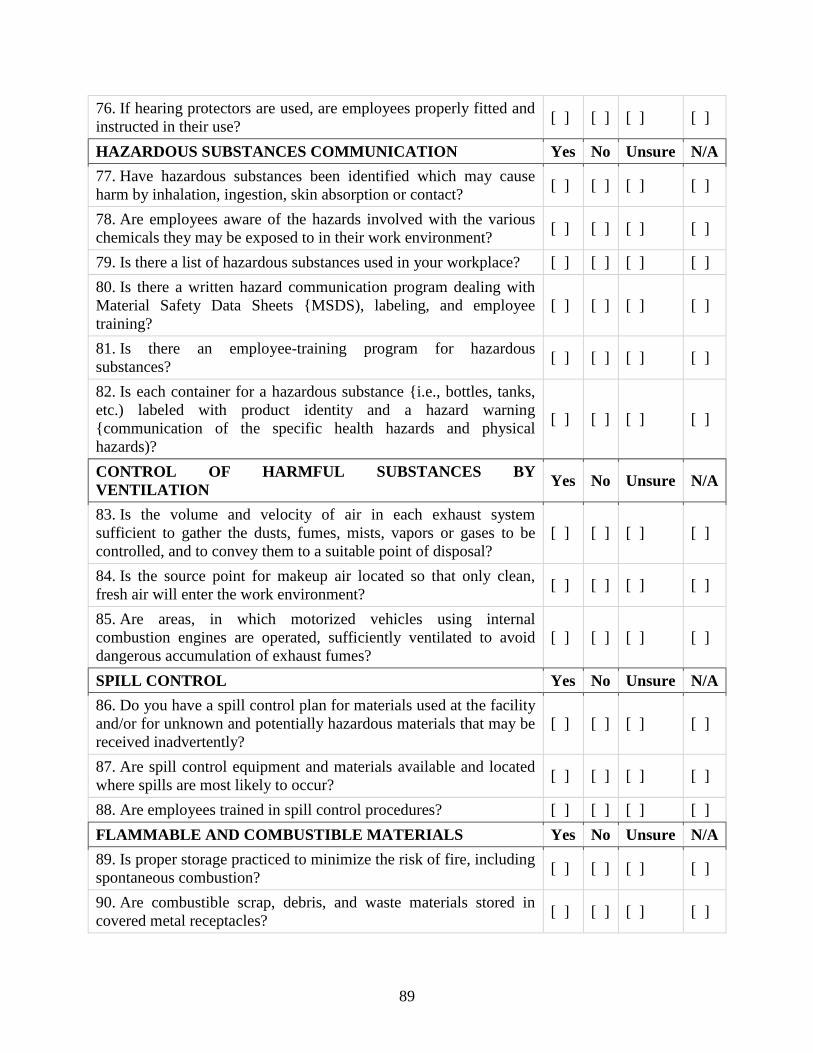
89
76. If hearing protectors are used, are employees properly fitted and
instructed in their use? [ ] [ ] [ ] [ ]
HAZARDOUS SUBSTANCES COMMUNICATION Yes No Unsure N/A
77. Have hazardous substances been identified which may cause
harm by inhalation, ingestion, skin absorption or contact? [ ] [ ] [ ] [ ]
78. Are employees aware of the hazards involved with the various
chemicals they may be exposed to in their work environment? [ ] [ ] [ ] [ ]
79. Is there a list of hazardous substances used in your workplace? [ ] [ ] [ ] [ ]
80. Is there a written hazard communication program dealing with
Material Safety Data Sheets {MSDS), labeling, and employee
training?
[ ] [ ] [ ] [ ]
81. Is there an employee-training program for hazardous
substances? [ ] [ ] [ ] [ ]
82. Is each container for a hazardous substance {i.e., bottles, tanks,
etc.) labeled with product identity and a hazard warning
{communication of the specific health hazards and physical
hazards)?
[ ] [ ] [ ] [ ]
CONTROL OF HARMFUL SUBSTANCES BY
VENTILATION Yes No Unsure N/A
83. Is the volume and velocity of air in each exhaust system
sufficient to gather the dusts, fumes, mists, vapors or gases to be
controlled, and to convey them to a suitable point of disposal?
[ ] [ ] [ ] [ ]
84. Is the source point for makeup air located so that only clean,
fresh air will enter the work environment? [ ] [ ] [ ] [ ]
85. Are areas, in which motorized vehicles using internal
combustion engines are operated, sufficiently ventilated to avoid
dangerous accumulation of exhaust fumes?
[ ] [ ] [ ] [ ]
SPILL CONTROL Yes No Unsure N/A
86. Do you have a spill control plan for materials used at the facility
and/or for unknown and potentially hazardous materials that may be
received inadvertently?
[ ] [ ] [ ] [ ]
87. Are spill control equipment and materials available and located
where spills are most likely to occur? [ ] [ ] [ ] [ ]
88. Are employees trained in spill control procedures? [ ] [ ] [ ] [ ]
FLAMMABLE AND COMBUSTIBLE MATERIALS Yes No Unsure N/A
89. Is proper storage practiced to minimize the risk of fire, including
spontaneous combustion? [ ] [ ] [ ] [ ]
90. Are combustible scrap, debris, and waste materials stored in
covered metal receptacles? [ ] [ ] [ ] [ ]

90
a. Are they removed from work areas daily? [ ] [ ] [ ] [ ]
91. Are approved containers and tanks used for the storage and
handling of flammable and combustible liquids? [ ] [ ] [ ] [ ]
92. Are all flammable liquids kept in closed containers when not in
use (e.g. parts cleaning tanks, etc.)? [ ] [ ] [ ] [ ]
93. Are fire extinguishers selected and provided for the types of
materials in areas where they are to be used? [ ] [ ] [ ] [ ]
94. Are extinguishers free from obstructions or blockage? [ ] [ ] [ ] [ ]
95. Are all extinguishers fully charged and in their designated
places? [ ] [ ] [ ] [ ]
96. Are NO SMOKING signs posted where appropriate? [ ] [ ] [ ] [ ]
FUELING Yes No Unsure N/A
97. Is it prohibited to fuel an internal combustion engine with a
flammable liquid while the engine is running? [ ] [ ] [ ] [ ]
98. Are fueling operations done in such a manner that likelihood of
spillage will be minimal? [ ] [ ] [ ] [ ]
99. When spillage occurs during fueling operations, is the spilled
fuel washed away completely, evaporated, or other measures taken
to control vapors before restarting the engine?
[ ] [ ] [ ] [ ]
100. Are fuel tank caps replaced and secured before starting the
engine? [ ] [ ] [ ] [ ]
101. Is handling or transferring gasoline in open containers
prohibited? [ ] [ ] [ ] [ ]
102. Is smoking prohibited in the vicinity of fueling operations? [ ] [ ] [ ] [ ]
MOTORIZED VEHICLES Yes No Unsure N/A
103. Are only employees who have been trained in the proper use
of industrial trucks allowed to operate them? [ ] [ ] [ ] [ ]
104. Are lift truck operating rules posted? [ ] [ ] [ ] [ ]
105. Are motorized vehicles with internal combustion engines
operated in enclosed areas carefully checked to ensure such
operations do not cause a harmful concentration of dangerous gases?
[ ] [ ] [ ] [ ]
106. Are motorized vehicles inspected daily or prior to use? [ ] [ ] [ ] [ ]
a. If yes, are inspections documented? [ ] [ ] [ ] [ ]
107. Are trucks shut off and the brake set prior to loading or
unloading? [ ] [ ] [ ] [ ]
108. Are bollards or other similar devices used to protect the
building or machinery inside the building from collision with a
moving vehicle or forklift?
[ ] [ ] [ ] [ ]

91
109. Does each motorized vehicle have a warning horn, whistle,
gong, or other device which can be clearly heard above the normal
noise in the areas where operated
[ ] [ ] [ ] [ ]
MATERIAL HANDLING Yes No Unsure N/A
110. Is there safe clearance for equipment through aisles and
doorways? [ ] [ ] [ ] [ ]
111. Are aisle ways designated, permanently marked, and kept
clear to allow unhindered passage? [ ] [ ] [ ] [ ]
112. Are trucks shut off and the brake set prior to loading or
unloading? [ ] [ ] [ ] [ ]
113. Are trucks and trailers secured from movement during
loading and unloading operations? [ ] [ ] [ ] [ ]
114. Are dock plates and loading ramps constructed and
maintained with sufficient strength to support imposed loading? [ ] [ ] [ ] [ ]
115. Are hand trucks maintained in a safe operating condition? [ ] [ ] [ ] [ ]
116. Are chutes equipped with sideboards of sufficient height to
prevent materials from falling off? [ ] [ ] [ ] [ ]
117. Are skids and pallets inspected before being loaded or
moved? [ ] [ ] [ ] [ ]
MACHINE GUARDING Yes No Unsure N/A
118. Is there a training program to instruct employees on safe
methods of machine operation? [ ] [ ] [ ] [ ]
a. If yes, are employees tested or otherwise certified in someway
that they have been properly trained? [ ] [ ] [ ] [ ]
119. Is there a regular program of safety inspection of machinery
and equipment? [ ] [ ] [ ] [ ]
a. If yes, How often are inspections?
b. Are they documented? [ ] [ ] [ ] [ ]
120. Are provisions made to prevent machines from automatically
starting when power is restored after a power failure or shutdown? [ ] [ ] [ ] [ ]
121. Is all machinery and equipment kept clean and properly
maintained? [ ] [ ] [ ] [ ]
122. Is sufficient clearance provided around and between
machines to allow for safe operations, set-up and servicing, material
handling, and waste removal?
[ ] [ ] [ ] [ ]
123. Is equipment and machinery securely placed and anchored to
prevent tipping or other movement that could result in personal
injury?
[ ] [ ] [ ] [ ]

92
124. Is there a power shut-off switch within reach of the
operator's position at each machine? [ ] [ ] [ ] [ ]
125. Can electric power to each machine be locked out for
maintenance, repair, or security? [ ] [ ] [ ] [ ]
126. Are foot-operated switches guarded or arranged to prevent
accidental actuation by personnel or falling objects? [ ] [ ] [ ] [ ]
127. Are switches and valves used by a machine operator clearly
identified and readily accessible? [ ] [ ] [ ] [ ]
128. Are all emergency stop buttons colored red? [ ] [ ] [ ] [ ]
129. Are all pulleys and belts that are within 7 feet of the floor, or
at the working level, guarded? [ ] [ ] [ ] [ ]
130. Are methods provided to protect the operator and other
employees in the machine area from hazards created at the point of
operation, ingoing nip points, rotating parts, flying chips, and
sparks?
[ ] [ ] [ ] [ ]
131. Are fan blades protected with a guard having openings no
larger than one-half inch when operating within 7 feet of the floor? [ ] [ ] [ ] [ ]
LOCKOUT/TAG OUT PROCEDURES Yes No Unsure N/A
132. Is all machinery or equipment capable of movement required
to be de-energized or disengaged and blocked or locked-out during
cleaning, servicing, adjusting or setting up of operations?
[ ] [ ] [ ] [ ]
133. Is the locking-out of control circuits in lieu of locking-out
main power disconnects prohibited? [ ] [ ] [ ] [ ]
134. Does the lockout procedure require that stored energy
(mechanical, hydraulic, air, etc.) be released or blocked before
equipment is locked-out for repairs?
[ ] [ ] [ ] [ ]
a. Are appropriate employees provided with individually keyed
personal safety locks? [ ] [ ] [ ] [ ]
135. Are employees required to keep personal control of their
key(s) while they have safety locks in use? [ ] [ ] [ ] [ ]
136. Is it required that only the employee, exposed to the hazard,
place or remove the safety lock? [ ] [ ] [ ] [ ]
137. Are employees required to check the safety of the lockout by
attempting a start up after making sure no one is exposed? [ ] [ ] [ ] [ ]
138. Is there a means provided to identify any or all employees
who are working on locked-out equipment by their locks or
accompanying tags?
[ ] [ ] [ ] [ ]
139. Are a sufficient number of tags and padlocks provided for
any reasonably foreseeable repair emergency? [ ] [ ] [ ] [ ]

93
140. When machine operations, configuration, or size requires the
operator to leave his or her control station to install tools or perform
other operations, and that part of the machine could move if
accidentally activated, is such a component required to be separately
locked or blocked out?
[ ] [ ] [ ] [ ]
141. In the event that equipment or lines cannot be shut down,
locked-out and tagged, is a safe job procedure established and
rigidly followed?
[ ] [ ] [ ] [ ]

94
APPENDIX B: GLOSSARY OF TERMS
Bale- A compacted and bound cube of recycled material.
Baler- Equipment that compacts and binds recyclable materials to reduce volume and transportation costs. A
glossary of technical terms regarding baler types and operations may be found at
http://www.recyclingtoday.com/articles/article.asp?MagID=1&ID=3600&IssueID=80.
Beneficiation- The mechanical processing of waste glass to decontaminate it and crush it to a more uniform size
(see cullet).
Bimetal Can- A food or beverage can with a steel body and an aluminum lid: it is 100% recyclable by the steel
industry.
Boxboard- Paperboard used for fabricating boxes. Different boxboard grades are classified as to the composition of
the top liner, filler (middle layer), and back liner. It includes folding boxboard (cereal boxes), setup boxboard (shoe
boxes), and foodboard (milk cartons).
Broke- Paper that has been discarded anywhere in the process of manufacture in the paper mill.
Brown Goods- Obsolete electronic products, such as radios and televisions. The term is losing ground in common
usage to e-waste or e-scrap as computers become the dominant electronic waste.
Buy-Back Center- A recycling facility that purchases small amounts of secondary materials from the public.
CESQG- Conditionally exempt small quantity generator. Businesses that generate hazardous wastes in such small
quantities they are exempt from certain disposal regulations.
Co-Collection- The collection of bagged recyclables together with other municipal garbage, separated later for
recycling or disposal.
Commingled- Mixed recyclables that are collected or processed together.
Containerboard- The component materials used in the fabrication of corrugated cardboard.
Conveyor- a mechanism, usually a motorized belt, used to continuously move materials from one point to another.
An excellent glossary of technical terms relating to conveyors and conveyor types can be found at
http://www.flostor.com/library/glossary_a-b.htm or
http://www.cisco-eagle.com/systems/conveyors/glossary/glossary.htm
Corrugated cardboard- Layers of paper glued together with a ruffled or grooved inner liner. This is the material,
which makes corrugated cardboard boxes (the most recycled product in the country).
CPO- Computer print out paper.
Crusher/blower- A machine that flattens aluminum cans then pneumatically transfers the material to a trailer.
Cullet- Crushed glass which can be added to a batch of new materials in the manufacturing of new glass products. It
increases the rate of heat gain by batch and reduces fuel costs. Domestic cullet if produced in house during the
manufacturing process. Foreign cullet if it comes from an external source.
Curbside Collection - the collection of solid waste, recyclables, or other materials placed in front of the property
(curbside) by the generator who then returns the container to their normal location after they have been emptied.
Curbside collection is generally used in the collection of residential solid wastes and recyclables, or other materials.
It is not normally used in commercial, institutional or industrial solid waste collection.
Deinking- A process that removes inks, dyes or other contaminants from collected wastepaper.

95
Detinner- A company that buys tin mill products, removes the tin through appropriate processes and sells the
detinned steel, to steel mills and foundries and the recovered tin on the tin market.
Disk Screen- A device used to separate materials by size and weight. A series of disks are spaced on a series of
spaced axles to form a screen bed. As the axles and disks spin they propel oversized material across the bed while
undersized materials fall between the disks. Inclining and tilting the bed allows a weight-based separation as
heavier materials move down the tilt as lighter materials are propelled up the incline by the disks. Disk and axle
spacing, disk shape and size (oval, finger, star), disk material, incline and tilt may all be varied to optimize the sorts
desired. Frequently used in MRFs to separate OCC and paper from containers.
Eddy current separator- A separation device which uses either powerful spinning, permanent magnets or pulsed
electromagnets that produce repelling forces on non-ferrous metals. They are typically used by recyclers to
positively-sort aluminum cans or to remove bits of metal contamination from granulated plastics or glass cullet.
E-scrap (e-waste)- obsolete electronic equipment including computers, monitors, VCRs, televisions, etc. (see:
brown goods)
Ferrous Metals (FE)- metals, which are predominantly composed of iron. Most ferrous metals, with the exception
of some stainless steels, are magnetic.
Filestock- A specialty grade of (mixed) office type papers that is derived from discarded files. These may come
from offices, record storage, records centers, archives, libraries, etc. Mostly white and colored ledger but may also
include carbonless paper, bleached file folders etc.
Flow Control Law- Local ordinance controlling, or giving a municipal official authority to control the collection
and/or disposal of municipal solid waste produced in a specific geographical area.
Gaylord Container- The trade name for a large, reusable corrugated container used for shipping materials - usually
about one cubic yard in size.
Hard mixed paper- This classification of recovered paper typically includes Kraft paper, corrugated cardboard, and
office paper—all paper with longer fibers. Paperboard packaging can also be included.
High Density Polyethylene (HDPE)- Used to make plastic bottles, milk cartons and other products. It produces
toxic fumes when burned. Often referred to as No.2 Plastic.
High grade papers- Usually deinked, these primarily include printed and unprinted white papers collected from
converting operations, printing plants and offices.
Linerboard- A paperboard used as the facing material in the production of corrugated shipping containers. See also:
Test Linerboard.
Low Density Polyethylene (LDPE)- Often referred as No.4 Plastic.
Materials Recovery Facility (MRF)- A recycling facility that sorts and processes collected mixed recyclables into
individual streams for market. Also known as an intermediate processing center (IPC).
Mixed paper- The commingling of various paper grades, such as old mail, paperboard packaging, magazines, copy
and computer paper, egg cartons, etc. for recycling.
Negative Sort- Refers to when a desired recyclable is left on the sorting belt while contaminants and other
recyclables are removed. Negative sorts are used to minimize handling when the bulk of the stream to be sorted
consists of one material. Often used after mechanical separation for quality control.
Newsprint- Alternate term for the low-grade paper used to make newspaper.
#6 News- Baled newspaper typically generated from news drives and curbside collections. Prohibitive materials may
not exceed 1%. Total outthrows may not exceed 5%.
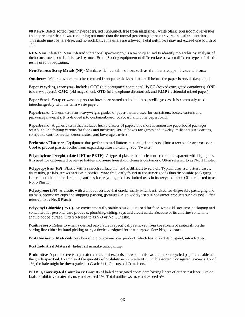
96
#8 News- Baled, sorted, fresh newspapers, not sunburned, free from magazines, white blank, pressroom over-issues
and paper other than news, containing not more than the normal percentage of rotogravure and colored sections.
This grade must be tare-free, and no prohibitive materials are allowed. Total outthrows may not exceed one fourth of
1%.
NIR- Near InfraRed. Near Infrared vibrational spectroscopy is a technique used to identify molecules by analysis of
their constituent bonds. It is used by most Bottle Sorting equipment to differentiate between different types of plastic
resins used in packaging.
Non-Ferrous Scrap Metals (NF)- Metals, which contain no iron, such as aluminum, copper, brass and bronze.
Outthrow- Material which must be removed from paper delivered to a mill before the paper is recycled/repulped.
Paper recycling acronyms- Includes OCC (old corrugated containers), WCC (waxed corrugated containers), ONP
(old newspapers), OMG (old magazines), OTD (old telephone directories), and RMP (residential mixed paper).
Paper Stock- Scrap or waste papers that have been sorted and baled into specific grades. It is commonly used
interchangeably with the term waste paper.
Paperboard- General term for heavyweight grades of paper that are used for containers, boxes, cartons and
packaging materials. It is divided into containerboard, boxboard and other paperboard.
Paperboard- A generic term that includes heavy classes of paper. The most common are paperboard packages,
which include folding cartons for foods and medicine, set-up boxes for games and jewelry, milk and juice cartons,
composite cans for frozen concentrates, and beverage carriers.
Perforator/Flattener- Equipment that perforates and flattens material, then ejects it into a receptacle or processor.
Used to prevent plastic bottles from expanding after flattening. See: Twister.
Polyethylene Terephthalate (PET or PETE)- A type of plastic that is clear or colored transparent with high gloss.
It is used for carbonated beverage bottles and some household cleanser containers. Often referred to as No. 1 Plastic.
Polypropylene (PP)- Plastic with a smooth surface that and is difficult to scratch. Typical uses are: battery cases,
dairy tubs, jar lids, straws and syrup bottles. More frequently found in consumer goods than disposable packaging. It
is hard to collect in marketable quantities for recycling and has limited uses in its recycled form. Often referred to as
No. 5 Plastic.
Polystyrene (PS)- A plastic with a smooth surface that cracks easily when bent. Used for disposable packaging and
utensils, styrofoam cups and shipping packing (peanuts). Also widely used in consumer products such as toys. Often
referred to as No. 6 Plastic.
Polyvinyl Chloride (PVC)- An environmentally stable plastic. It is used for food wraps, blister-type packaging and
containers for personal care products, plumbing, siding, toys and credit cards. Because of its chlorine content, it
should not be burned. Often referred to as V-3 or No. 3 Plastic.
Positive sort- Refers to when a desired recyclable is specifically removed from the stream of materials on the
sorting line either by hand picking or by a device designed for that purpose. See: Negative sort.
Post Consumer Material- Any household or commercial product, which has served its original, intended use.
Post Industrial Material- Industrial manufacturing scrap.
Prohibitive-A prohibitive is any material that, if it exceeds allowed limits, would make recycled paper unusable as
the grade specified. Example- if the quantity of prohibitives in Grade #12, Double-sorted Corrugated, exceeds 1/2 of
1%, the bale might be downgraded to Grade #11, Corrugated Containers.
PSI #11, Corrugated Containers: Consists of baled corrugated containers having liners of either test liner, jute or
kraft. Prohibitive materials may not exceed 1%. Total outthrows may not exceed 5%.

97
PSI #12, Double-Sorted Corrugated: Consists of baled, double-sorted corrugated containers generated from
supermarkets and/or industrial or commercial facilities. They have liners or test liners made from jute or kraft.
Materials must be sorted to eliminate boxboard, off-shore corrugated, plastic and wax. Prohibitive materials may not
exceed 1%. Total outthrows may not exceed 2%. Double-sorted corrugated has more rigid specifications, especially
the restriction on offshore corrugated and wax. Offshore corrugated generally applies to materials derived from
areas, such as some Asian countries, that are fiber poor and produce low strength, off-color corrugated materials.
Pulp- The solution resulting from blending wood, recovered paper or, in some cases, cotton with water to break it
down into individual cellulose fibers. This is the fibrous material used to make paper.
Recovered paper grades- These are the classifications of different types of recovered paper, each with its own
value to manufacturers. While there are dozens of specific grades, they can be grouped into four categories-
corrugated/Kraft paper, newspapers, high-grade papers and mixed papers.
Regrind- Ground up recyclable plastics. Often used to refer to manufacturing scrap returned to the manufacturing
process.
Resource Recovery- Any process of obtaining matter or energy from materials formerly discarded. A Resource
Recovery Facility is usually used to refer to a waste-to-energy facility with a front-end system for recovering some
recyclable materials.
Soft mixed paper- Typically includes magazines and newspapers—or papers with shorter fibers. Paperboard
packaging may also be included.
Sorted office paper- A mix of papers collected for recycling that includes white and pastel copy and writing paper;
white, green-bar and multi-stripe computer paper; letterhead and envelopes; notepads; advertising booklets, and
fliers.
Source-Separation (source-separated) – (1) The separation of recyclables from the waste stream by the generator
with the intent of recovering them for economic use. (2) The sorting of specific recyclables by type prior to their
collection or deposition into a collection container. May also refer to recyclables sorted at the curb by collection
personnel (curb-sort).
Special Wastes- Any waste requiring special handling such as scrap tires, used motor oil, hospital wastes or
household hazardous wastes.
Steel (Tin) Can- A rigid container made exclusively or primarily of steel. When used for food, it will often have a
thin layer of tin. It is 100% recyclable.
Stickies- Paper contaminants, which includes adhesives, thermal plastics, hot melts or other substances, which are
not water-soluble.
Test Linerboard- Linerboard that is made exclusively out of recycled materials such as double-lined kraft cuttings
and old corrugated containers.
Transfer Station- A facility where waste is taken by small collection vehicles and loaded into larger vehicles for
transport to a landfill or incinerator.
Trommel- A rotary cylindrical screen that is typically inclined at a downward angle that, combined with the
tumbling action of the trommel, separates materials of different density. Trommel screens are used by material
recovery facilities to separate paper from glass and other contaminants. Smaller trommels have been used to separate
labels and caps from crushed glass. Some trommels are designed to let paper pass through the screen while diverting
heavier materials to re-crushing or a landfill. Other applications require multi-stage trommel screens, which have
meshes or plates of different aperture sizes. These screens may be used for the separation of commingled materials
with components of various sizes.
Twister- An alternative to a flattener/perforator, it is an auger/extruder device used to compact plastic bottles by
twisting them. The manufacturer claims the plastic‘s memory is overcome and the bottles do not re-expand.
UBC- An acronym for Used Beverage Containers. More often used to refer to used aluminum beverage cans.

98
White office paper (White ledger)-A mix of paper collected for recycling that includes white copy paper and
writing paper; white, green-bar and multi-stripe computer print-out; and white envelopes without plastic windows or
labels.

99

100
REFERENCES
1. “Best Practice Guide for HDPE Recycling”, Clean Washington Center, Seattle, WA,
1997
2. “Best Practices in Glass Recycling”, Clean Washington Center, Seattle, WA, November
1996
3. “Best Practices in PET Recycling”, Clean Washington Center, Seattle, WA, 1997
4. ―Handling Plastics in a Materials Recovery Facility: Optimization of Actual Operations,
Final Report‖, Environment and Plastics Industry Council, Mississauga, ON.
5. “How to Prevent Stormwater Pollution at a Scrap and Waste Recycling Facility”, City of
Los Angeles, Dept. of Public Works.
6. ―Manual of Recommended Safety Practices‖, Environmental Industry Associations,
Washington, D.C., March, 2001.
7. ―Material Recycling Facility Quality Improvement Series: MRF Evaluation Program‖,
Solid and Hazardous Waste Education Center, University of Wisconsin – Extension,
April, 2004.
8. ―Materials Recovery Facilities Operational Assessment Final Report and Optimization
Guide”, Minnesota Office of Environmental Assistance, St. Paul, MN, August, 2003.
9. ―Safety Assessment Form: Recycling Facility‖, Kansas Department of Health and
Environment, Topeka, KS.
10. ―Sorting Plastic Bottles for Recycling‖, American Plastics Council, Arlington, VA,
February, 2000.
11. Harler, Curt, ―Benchmark Your UBC Operation Against the Best‖, Recycling Today,
September, 1998.
12. O‘Malley, Penelope Grenoble, ―Preventive Maintenance is Key to Keeping MRFs Up and
Running‖, MSW Management, March/April 2005.
13. Perkins, Ron, and Dunbar, Judith, ―Optimizing Plastics Recovery From Single Stream
MRFs‖, Resource Recycling, February, 2005.
14. Pytlar, Theodore S., “Trends in Material Recovery Facility Modernization”, Resource
Recycling, October, 2004.
15. Woods, Randy, “The Bumpy Ride”, Waste Age, June 2004.