Best Available Copy (Cont'd) Page FULL SCALE FATIGUE TEST OF CT-114 TUTOR WING 15 First Phase...
82
" R"PRrpnIICFD AT G(0vt RNMFNT FXPFNSE "UNLIMITED Canada a* UNCLASSIFIED C 0 • A HISTORY OF FULL-SCALE TESTING OF AIRCRAFT STRUCTURES AT THE i o NATIONAL AERONAUTICAL ESTABLISHMENT uric QELE -CTEf APP, 0 5 by * R.L. Hewitt National Aeronautical Establishment l--- pZ-_ _ j. AER(ONAUTICAL NOTE * • OTTAWA NAE-AN-24 JANUARY 1985 NRC NO. 24089 n, National Research Conseil national r Council Canada de recherches Canada 85 03 13 011 6 ::::,:
Transcript of Best Available Copy (Cont'd) Page FULL SCALE FATIGUE TEST OF CT-114 TUTOR WING 15 First Phase...

" R"PRrpnIICFD AT G(0vt RNMFNT FXPFNSE
"UNLIMITED Canada a*UNCLASSIFIED
C
0 • A HISTORYOF FULL-SCALE TESTINGOF AIRCRAFT STRUCTURESAT THEi
o NATIONAL AERONAUTICAL
ESTABLISHMENT
uricQELE -CTEf
APP, 0 5by
* R.L. HewittNational Aeronautical Establishment
l---
pZ-_ _ j.
AER(ONAUTICAL NOTE
* • OTTAWA NAE-AN-24
JANUARY 1985 NRC NO. 24089
n, National Research Conseil nationalr Council Canada de recherches Canada
85 03 13 011
6 ::::,:

BestAvailable
Copy
J• . .. . . . r.J --.. c•- . * = , •.) .- .• : _• • • • • ,. .=
RFPRODUCFD AT GOVERNMENT FXPENSE
NATIONAL AERONAUTICAL ESTABLISHMENT
SCIENTIFIC AND TECHNICAL PUBLICATIONS
AERONAUTICAL REPORTS:
Aeronautical Reports (LR): Scientific and technical information pertaining to aeronautics consideredimportant, complete, and a lasting contribution to existing knowledge,
Mechanical Engineering Reports (MS): Scientific and technical information pertaining to investigationsoutside aeronautics considered important, complete, and a lasting contribution to existing knowledge.
AERONAUTICAL NOTES (AN): Information less broad in scope but nevertheless of importance as acontribution to existing knowledge.
LABORATORY TECHNICAL REPORTS (LTR): Tnformation receiving limited distribution because"of preliminary data, security classification, proprietary, or other reasons.
Details on the availability of these publications may be obtained from:
Publications Section,National Research Council Canada,National Aeronautical Establishment,Bldg. M-16, Room 204,Montreal Road,Ottawa, OntarioKIA 0R6
ETABLISSEMENT AERONAUTIQUE NATIONAL
PUPLICATIONS SCIENTIFIQUES ET TECHNIQUES
RIAPPORTS D'AERONAUTIQUE
Rapports d'aironautique (LR): Informations scientifiques et techniques touchant l'a~ronautiquejug~es importantes, completes et durables en termes de contribution aux connaissances actuelles.
Rapports de ginie m~canique (MS): Informations scientifiques et techniques sur la recherche extemel'aeronautique jug~es importantes, completes et durables en termes de contribution aux connais-
sances actuelles.
"CAHIERS D'AkRONAUTIQUE (AN): Informations de moindre portte mais importantes en termesd'accroissement des connaissances.
RAPPORTS TECHNIQUES DE LABORATOIRE (LTR): Informations peu dis~min~es pour desraisons d'usage secret, de droit de propri6th ou autres ou parce qu'elles constituent des donn6esprhliminaires.
Les publications ci-dessus peuvent 6tre obtenues ii l'adresse suivante:
Section des publicationsConseil national de recherc) es CanadaEtablissement a~ronautique nationalIm. M-16, pi,5ce 204Chemin de Montr6al
q Ottawa (Ontario)KlA 0R6
•'.• w-- " mw ' •,.-

REPRCDUCED AT GOVERNMENT EXPENSL.
0
UNLIMITEDUNCLASSIFIED
A HISTORY OFFULL-SCALE TESTING OF AIRCRAFT STRUCTURES ATTHE NATIONAL AERONAUTICAL ESTABLISHMENT
L'HISTOIRE DELEVALUATION EN LABORATOIRE DE STRUCTURES D'AERONEFSA LETABLISSEMENT AkRONAUTIQUE NATIONAL
* Accession For
DDIC T,
by/par '0COPYcoy__INSPECTED
R.L. Hewitt Dt4
National Aeronautical Establishment Av ,_i'llity Codes
"Dist 4Cclal
AERONAUTICAL NOTEOTTAWA NAE-AN-24JANUARY 1985 NRC NO. 24089
W. Wallace, Head/ChefStructures and Materials Laboratory G.M. LindbergLaboratoire des structures et matiriaux Director/Directeur
"SUMMARY
This report presents an historical review of the work of theStructures and Materials Laboratory of NAE in the area of full scale testingof large aircraft structures. It covers the period from 1941 to 1984, startingwith a static strength test of a moulded wood Anson fuselage and finishingwith a fatigue test of a Grumman Tracker wing. Brief details of the loadingarrangements and test results are included for each test component andthese are used to trace the uevelopment of the laboratory from the use ofrulers and shot bags to computer-controlled servo-hydraulic actuators.
RESUME
Le pr6sent rapport fait une r6capitulation historique du travail du"Laboratoire des structures et des mat~riaux de I'EAN dans le domaine del'6valuation en laboratoire de structures d'a6ronefs.. II couvre la pOriodeallant de 1941 a 1984, en commengant par l'essai de r6sistance statique d'unfuselage Anson en bois et en terminant pas un essal de fatigue de l'aile d'unGrumman Tracker. De brefs d6tails sur leE conditions de charge et les
*- r~sultats 0-' essais sont 6galement inclus pour chaque essai, eý ces d~tailsservent A retracer les progr6s au laboratoire depuis l'emploi de r6gles imesurer et de sacs de grenaille de plomb i l'emploi de verins servo-hydrauliques command6s par ordinateur.
0
(iii
- . .. .. .. - -. - \ .d - - . . . ..
CONTENTS
Page
SUMMARY ...................................... (iii)
TABLE .,...... ............ (v)
ILLUSTRATIONS ......................................... ........... (v)
INTRODUCTION. ........ ............................. ., . . 1
STATIC TEST OF MOULDED WOOD ANSON FUSELAGE.... ................. ........ 1
TIGER MOTH MAINPLANES ........ 1. ................. 1
HARVARD II MAINPLANES_............................. 2
MOULDED WOOD HURRICANE WING PANEL................ 2.....2
MOULDED PLYWOOD HARVARD FUSELAGE .................... ......... 2
ANSON MAINPLANES AND TAILPLANES ,..,.,................ .......... 3
DROP TEST OF A CORNELL AIRCRAFT,...... ..... , ............ 3
NRL HYDRAULIC STATIC TESTING APPARATUS,,,.......................... ...... ,. 4
MOSQUITO WINGS .................................................. ... ...... 5
C-102 DERWENT EMPENNAGE .,.. .... 6
C-102 DERWENT MAINPLANE AND CENTRE FUSELAGE ............. ............ 7
TEXAN T6 MAINPLANE.,........... .............................. .......... 7
STATIC TESTS ON C-100............. ........................ 7
REPEATED LOAD TEST ON CF-100 WING PANELS ........................... 8
MENTOR WING ........................... 9
REPEATED LOAD TESTS ON HARVARD OUTER WINGS.._.................. . .:. 10
REPEATED LOAD TEST ON CF-100 OUTER WING ., ................. .. •. 11
4 SABRE 5 HORIZONTAL STABILIZERS........................ .......... ...... 11
FOUND BROTHERS FBA-2 AIRFRAME ..... .*....... ..... 11
FULL SCALE FATIGUE TEST OF CF-100 AIRCRAFT .,,. ,_ .,,,. _ • ,. 12
Wing-Fuselage Test .2......... 1
Horizontal Stabilizer Test... ........ ............. 14
(iv)
.!

CONTENTS (Cont'd)
Page
FULL SCALE FATIGUE TEST OF CT-114 TUTOR WING .......................... 15
First Phase Fatigue Test - Trainer Role ............. ......... . ...... 15Sec•ond Phase Fatigue Test - Snowbird Role ................. ....... 17
FULL SCALE FATIGUE TEST OF CS2F TRACKER WING, ....................... is
CONCLUSIONS ...................... ...... .... 20
"REFERENCES. ...... .......... . 20
Table 1 La'ge Scale Tests at NAE/NRC ............. ...... . . ........ 27
ILLUSTRATIONS
Figure Page
1 Proof Load Test on an 800 Hour Tiger Moth Wing..........-... ............. . 29
2 Proof Load Test on an 800 Hour Tiger Moth Wing....,,_ . .......... 30
3 Harvard II Mainplane at 90% Specified Ultimate Load ............ 31
4 Harvard II Mainplane Showing 'Normal' Wrinkling at 90% Ultimate SpecifiedLoad ... , ....................... . . . .... . . . . ...... .. ............ 32
5 Moulded Wood Hurricane Wing Panel ............................... . 33
6 Moulded Plywood Harvard Fuselage U-nder Ultimate Design Load for a SpecialTailwheel Ccndition After R-.nair ................... .. . ............... 34
7 Horizontally Mounted Test of Moulded Plywood Harvard Fuselage ............ 35
8 Failure of Moulded Plywood Harvard Fuselage Under a Special Tailwheel- Condition .......... ....... ...... 36
9 Static Test of Moýulded Plywood Harvard Stabilizer ............................ 37
10 Static Test of Moulded Plywood Harvard Elevator ............................. 38
4 11 Test of Anson I Mainpiane Showing Slats Used to Distribute Shot Bag Weights 39
12 Anson Mainplane Under Load Showing Whiffletree for Applying Engine and"Undercarriage Loads .... 40
13 Test Set-Up for Anson Tailplane .................. ........... 41
14 Drop Test of a Cornell Aircraft.. .... ........... 42
(v)
. .

ILLUSTRATIONS (Cont'd)
Figure Page
15 Te.' Set-Up for Cornell Wing ........................................... 43
16 Typical Wing Set-Up in NRL Static Test Facility .............. ....... 44
17 Failure of a Used Mosquito Wing at 95% Ufltimate Factored Load ......... 45
18 Test of C-102 Derwent Fin .................................. ......... 46
19 Test of C-i02 Derwent Tailpiane. .... ... I............. ...... 47
20 Test Set-Up tor C-102 Derwent Mainplane and Centre Fuselage................... 48
21 NRL 200 Channel Strain Recorder . ...................... .... 49
22 Test of C-100 Tailplane .. ........................ 50
23 Test Set-Up for C-100 Outer Wing Showing Riveted Attachmems to LeadingEdge .............................. ..................... ... 51
"24 C-100 Empennage Under Proof Load................................... 52
2"25 Loading at the Centre Elevator Hinge of C-100 TailplP4le Thowing Application
of a Couple to the Hinge and Close-Up of Load Cll ...... . .......... 53
26 Automated Repeated Limit Load Test on C-100 Yark 3 Oute; Wing ............. 54
27 Automatic Loading System for Repeated Load Tests ....................... 55
*:-. 28 Photograph and Schematic of Repeated Load Balancing System................... 56
29 Static Test Set-Up for Found Brothers FBA-2 Airframe................. .. 57
30 C-.100 Wing-Fuselage Test Arrangement - Front Elevation .................... 58
31 C-100 Wing-Fuselage Test Arrangement - Side Elevation .................... 59
* 32 C-100 Wing-Fuselage Fatigue Test Arrangement ......................... 60
33 Test Load History 'or C-100 Tailplane .... . ............. ....... 61
34 C-100 Tail Unit Test Arrangement - Rear Elevatio........ ........ 62
* 35 C-100 Tail Unit Test Arrangement - Side Elevation ............... ..... 63
36 C-100 Tail Unit Fatigue Test Arrangement .... ....... . .................... 64
37 Block Diagram of Load Control System for C-100 'I iilplane Test.. ., ......... 65
380 View o F Tutr Fatigue Test Showing Wing Loading System
(vi)
*

1o
ILLUSTRATIONS (Cont'd)
Figure Page
39 Fuse' tge Loading System for Tutor Wing Fatiguc Test ......................... 67
40 Tutor Wing Fatigue Test Set-Up .......... ................ .... 68
41 Nine Level Low-High-Low Loading Sequence Used in Tutor • atigue Test(Trainer Role) ........ .......... ........ ......... 69
42 Ihacker Wing Fatigue Test Set-Up ....................... ................. 70
43 Under Fuselage Whiffletree System.............. ............... 71
44 Trmcker Wing Loading System................ ...... .......... 72
45 Nacelle Loading System ......................................... I ... 73
46 Outer Wii.g Loading System ................. .......................... 74
I(
;[ (vii)
....................................

S~-1-
A HISTORY OF
FULL-SCALE TESTING OF AIRCRAFT STRUCTURES AT
THE NATIONAL AERONAUTICAL ESTABLISHMENT
INTRODUCTION
The conduct of full-scale structural fatigue tests is both time consuming and expensive andrequires considerable expertise in all areas of structural fatigue including loads monitoring, structuraltesting, crack propagation analysis, non-destructive testing etc. Because of its mandate and areas ofinterest the Structures and Materials Laboratory of NAE is able to maintain a pool of this expertisewhich is available, together with the associated experimental facilities, for outside agencies when andas required.
As part af a larger review of current facilities and capabilities in the light of newdevelopments in both aieas, a review of the past work of the laboratory was undertaken and is pre-sented here. In general, orly large structures have been included. Many smaller components havebeen tested over the years but these were considered beyond the scope of this review. Similar'y,considerable work has been undertaken within the laboratory on the impact resistance of componentsand structures, but this is also beyond the scope of this paper.
STATIC TEST OF MOULDED WOOD ANSON FUSELAGE
One of the earliest fall scale tests on an aircraft structure performed by this laboratory,which was then the Structures Laboratory of the Division of Mechanical Engineering, was a statictest of a moulded wood Anson aircraft fuselagel1 ) in 1941. The test was conducted at the VidalResearch Corporation, New Rochelle, N.Y.. for the Royal Canadian Air Force (RCAF). The fuselagewas fitted with dummy mainplane spars, which were tid down to heavy steel girders laid on the floorand braced to the structural steel of the building. Loading was carried out by means of shot bags for"the down-loads and by a hydraulic jack and platform scale with a steel girder multiplying lever forthe tail-skid up-load.. Loading was applied on the floor boards of the fuselage, on a temporary frameon top of the fuselage and, for side loading, via a horizontal cable from a tubular member carried intwo wooden frames fitted to the fin, and then over a large diameter pulley to a weight platform.Deflections were measured by reading scales on the fuselage side with a surveyor's level or, for sideloading, by attaching scales to the fuselage with double sighting wires, to eliminate parallax, attachedto independent structures.
The structure was loaded to 75% of ultimate load at various intervals in both side and downloading and deflections noted, There were no indications of creep or permanent deformation.. Thefuselage was then tested to destruction for the down load without nose load as this was observed tobe the most critical loading case.. At 140% ultimate load a compression failure occurred just aft ofthe door. The report concluded that the fuselage had an a -equate margin of strength and that. thiscould be improved by judicious rearrangement of the weight of material used and some modificationof the structure to obtain a better stress distribution.
It is also interesting to note that the report recommended that the fuselage be madeavailable for weathering tests since it was without surface finish of any kind.
"TIGER MOTH MAINPLANES
One of the first tests within the laboratory was a static test of four upper mainplartes of"Tiger Moth Aeroplanes for the National Defence for Air in 1942(2). The object of these tests was todetermine to what extent the mainplanes were deteriorating in service due to doubtful gluing, andwings having 0, 400, 800 and 1000 flying hours were tested.
I . . . . . . . . . . . . . . . . : . : . . - . - : - . - . ,
* -2-
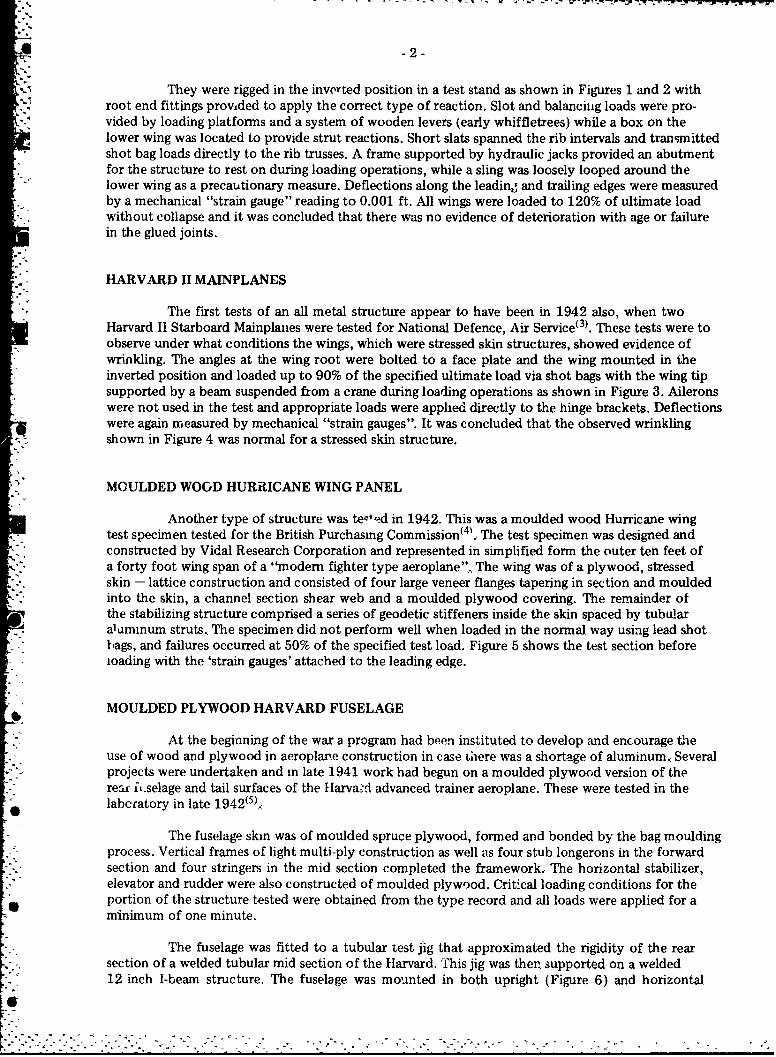
They were rigged in the invorted position in a test stand as shown in Figures 1 and 2 withroot end fittings provided to apply the correct type of reaction. Slot and balancing loads were pro-vided by loading platforms and a system of wooden levers (early whiffletrees) while a box on thelower wing was located to provide strut reactions. Short slats spanned the rib intervals and transmittedshot bag loads directly to the rib trusses. A frame supported by hydraulic jacks provided an abutmentfor the structure to rest on during loading operations, while a sling was loosely looped around thelower wing as a precautionary measure. Deflections along the leadin, and trailing edges were measuredby a mechanical "strain gauge" reading to 0.001 ft. All wings were loaded to 120% of ultimate loadwithout collapse and it was concluded that there was no evidence of deterioration with age or failurein the glued joints.
HARVARD II MAINPLANES
The first tests of an all metal structure appear to have been in 1942 also, when twoHarvard II Starboard Mainplanes were tested for National Defence, Air Service(3). These tests were toobserve under what conditions the wings, which were stressed skin structures, showed evidence ofwrinkling. The angles at the wing root were bolted to a face plate and the wing mounted in theinverted position and loaded up to 90% of the specified ultimate load via shot bags with the wing tipsupported by a beam suspended from a crane during loading operations as shown in Figure 3. Aileronswere not used in the test and appropriate loads were applied directly to the hinge brackets. Deflectionswere again measured by mechanical "strain gauges". It was concluded that the observed wrinkling
* :shown in Figure 4 was normal for a stressed skin structure.
MOULDED WOGD HURRICANE WING PANEL
Another type of structure was tewlod in 1942. This was a moulded wood Hurricane wingtest specimen tested for the British Purchasing Commission(4'.. The test specimen was designed andconstructed by Vidal Research Corporation and represented in simplified form the outer ten feet ofa forty foot wing span of a "modem fighter type aeroplane". The wing was of a plywood, stressedskin - lattice construction and consisted of four large veneer flanges tapering in section and mouldedinto the skin, a channel section shear web and a moulded plywood covering. The remainder ofthe stabilizing structure comprised a series of geodetic stiffeners inside the skin spaced by tubularaluminum struts. The specimen did not perform well when loaded in the normal way using lead shotbags, and failures occurred at 50% of the specified test load. Figure 5 shows the test section beforeioading with the 'strain gauges' attached to the leading edge.
MOULDED PLYWOOD HARVARD FUSELAGE
At the beginning of the war a program had been instituted to develop and encourage theuse of wood and plywood in aeroplane construction in case there was a shortage of aluminum., Severalprojects were undertaken and in late 1941 work had begun on a moulded plywood version of therear i .selage and tail surfaces of the Harva d advanced trainer aeroplane. These were tested in thelabcratory in late 1942(5),.
The fuselage skin was of moulded spruce plywood, formed and bonded by the bag mouldingprocess. Vertical frames of light multi-ply construction as well as four stub longerons in the forwardsection and four stringers in the mid section completed the framework.- The horizontal stabilizer,elevator and rudder were also constructed of moulded plywood. Critical loading conditions for theportion of the structure tested were obtained from the type record and all loads were applied for aminimum of one minute.
The fuselage was fitted to a tubular test jig that approximated the rigidity of the rearsection of a welded tubular mid section of the Harvard. This jig was then supported on a welded12 inch I-beam structure. The fuselage was mounted in both upright (Figure 6) and horizontal
....-... •.. -..• .- .,- . . . :. o.• - 7... *.., ,-.- . - , .:.-* *.*. ... .. •- .. . . •.. . . . . o..

-3-
positions (Figure 7) for various loading conditions and loads applied by means of lead weights andlead shot bags for down loads and by a hand hoist, scale balance and a steel i-, earn for up loads.Deflections were measured with a surveyors level and "strain gauges". All the design loads weresuccessfully carried except for a "special tailwheel condition B" which resulted in a failure of thelower skin fibres at 100% design load, Figure 8, due to a stress concentration at the sharp corner ofthe flare cut-out and lack of continuity of the short stiffeners which carried the flare tube brackets.After repair and modification the design load was successfully carried.
The stabilizer was mounted in a horizontal position and one third of the load appliedto the upper skin by shot bags, the remainder being applied by means of load pans and a linkagearrangement at seven stations spanwise and four chordwise, woodscrews being utilized to apply theforce to the skin at the stiffener, Figure 9. The elevator was mounted in a horizontal position andloaded in a similar manner to the stabilizer, Figure 10.
Since these tests were all satisfactory, a second unit was prepared for flight testing inSeptember 1943 and after preliminary flight trials at the RCAF Test and Development Establishment,Rockchffe, was assigned to routine flying at Uplands Air Station. The aircraft was later returned toNRC and assigned to test flying in connection with a stability investigation.
ANSON MAINPLANES AND TAILPLANES
In 1943 static tests were conducted on four Anson mainplanes for dhe Department ofNational Defence for Air(60 to determine the reduction in strength resulting from glue deteriorationin the spars of two condemned Anson I mainplanes and to determine the strength of a new Canadianbuilt mainplane for use in the Anson V aircraft. The 56.5 ft mainplane was loaded in the invertedposition using slats and shot bags in the normal way as shown i- Figure 11 while engine and under-carriage loads were provided by a crane react-.on through a whiffletree arrangement shown inFigure 12. Deflections were measured by the same mechanical "strain gauges" referred to above,although in this report they are called "tape strain gauges", while dial gauges were used to monitorthe deflection of the test stand. The condemned mainplanes, one classed as in "ver., bad condition"(and labelled "write-off") and one in "fairly bad condition" failed at 75% and 9C ' respectively ofthe design loading while the new mainplane faik!d at 95% dubign load.. It was concluded after observingthe failures that while the glue in the old spars (a cold setting urea formaldehyde) had deteriorated tosome extent, the mainplanes had not failed as a result of this deterioration, but had failed like ther -w one at the centre section of the tension spar where a 5/8 inch bolt hole reduced the sectior, As
esult of this observation, a further condemned mainplane in a similar condition to the previous twowas modified by the addition of a 5/8 inch birch lamination in the critical area. This modified wingfailed at 105% of the design load at a different location.
Similar tests were periormed on Anson tailplanes in the same year(7). Four tailplaneslabelled "bad case of glue failure", "unserviceable, repairable", "unserviceable" and "failed on gluetest" were found to sustain over 200% of the design load although it was observed that the glue inthe spars had deteriorated. It was concluded that this did not affect their strength, however, sincethey failed in simple bending. A test set-up for a tailplane is shown in Figure 13. An interesting aspectof these last two reports(6 .7) is that each contained full details of the load calculations.
DROP TEST OF A CORNELL AIRCRAFT
K' A different kind of full scale aircraft test was performed in 1944 when a drop test of acomplete Cornell aircraft was carried out for the Department of National Defence for Air(•8 todetermine whether landing gear loads might produce centre section spar damage which might latercontribute to structural failures in the air. This investigation was a result of several failures of Cornellwings m flight.
I.

* -4-
The aircraft tested was a Mvrk 11 Cornell made in Canada by Fleet Aircraft with Less than13 hours flying time. It was 1laded to its maximum gross weight with lead shot bags. The rear of thefuselage was pivottei on the floor by anchoring the tall wheel assembly and the aircraft lifted with achain hoist with a quick release mechanism attached to the slinging eye on the turnover structure asshown in Figure 14.: The drop height was measured from the floor to the bottom of the tire with thelanding gear extended to its extreme position. Tests were started with a 12 inch drop, then an 18 inchdrop followed by 3 inch increments until some failure occurred in the aircraft. The tires were arrestedby a concrete floor in the three point landing condition while for the drift condition they werearrested by two heavy timber ramps inclined at 150 to the horizontal to provide some side load onthe undercarriage. Vertical accelerations were measured in the three point landing condition byrecording accelerometers and the tests were photographed at 64 frames/second on 16mm film,
In the three point landing tests, minor damage occurred after ti,- 30 inch drop correspondingto about 4-1 !2g and the centre section wing skin failed after the 39 inch drop corresponding to about6-1/2g.
After replacing the damaged centre section, the side drift landing tests were conductedwhich resulted in a skin failure after a 21 inch drop, This was attributed to a malfunction of thelanding gear. After repairing the skin and replacing part of the landing gear, the skin showed nofailure until after the 30 inch drop. It was concluded that a landing shock of 6 to 7g was required tofail the centre section skin.
* Following on from these tests, static tests were performed on a Cornell wingt91, again for
the Department of National Defence Air., A complete wooden cantilever wing consisting of ýA centresection and removable outboard panels as shown in Figure 15 was loaded in the inverted position viashot bags on short slats spanning the rib intervals. During the loading operation the wing tip wassupported by jacks. Deflections were measured by "tape strain gauges" and the test stand deflectionschecked using Olal gauges. The tests indicated that the realized load factor on the wing was between 9and 10.
NRL HYDRAULIC STATIC TESTING APPARATUS
No major full-scale structural testing was performed in the next few years because of the_ decision to design and build a tailless glider in the Structures Laboratory' 1". This consumed both
space and manpower, and it was not until completion of the fabrication of this aircraft that full scale- testing resumed.
The resumption was at a much more sophisticated level, however, both because of an influxof new staff and because of a decision of the Executive Committee of the .' ssociate Committee onAeronautical Research"1 '). The Aircraft Structures Subcommittee had recommended the installation
- of a large static testing frame for testing Mosquito wings for the RCAF and for tests in connectionwith the A.V. Roe construction plans. They suggested it be designed and cor structed by A.V. RoeCanada at Malton and that it be serviced and maintained between tests by NRC. However, theExecutive Committee decided in January 1947 that it would be preferable to install a "meccano"type structural steel frame, similar to the equipment at Wright Field, in the Structures Laboratory at
*' NRC. It was considered that this would be more flexible than the conventional cathedral type frameproposed for Malton, Wings of any type, fuselages and other aircraft components could be tested bybolting together the required frame.
The apparatus was completed in early 1948'121 and the test structure itself remains in useto this day for full-scale aircraft fatigue testing. Tn its original form it was possible to test aircraftwings of 120 ft span and 18 ft 9 in. chord with a total upward load of 600,000 lbf plus appropriate
* down loads applied by hydraulic tension jacks.
The test structure consisted of a series of up to 12 gallows frames made up from commercialstructu-al steel sections in which holes were drilled at a standard gauge and pitch and assembled bybolting in the required arrangement,
- - . - - A * .-

I -5-
Four inverted T-section reinforced concrete beams were placed under the floor with two15 inch steel channels back to back and one inch apart securely anchored therein. The lower flanges"were welded to an 8 inch channel and the upper flanges were flush with the floor to provide aninverted T-shaped slot in the floor for anchoring the super-structure. The individual frames would becross-braced by means of tie rods fitted with turnbuckles and end frames could be braced to suitableadditional floor slots.
The main loads were applied by "Lancaster" aircraft hydraulic undercarriage reaction jackssuspe:,ded between the two channels forming the beams of the gallows frames by means of universaljoints bearing in cast iron saddles clamped to the channels, Two hydraulic consoles were availablewhich were each able to supply the hydraulic fluid at four different pressures simultaneously.
Loads were transmitted to the test article by means of "adhesive tension patches" which
were at that time being used in the CSIR laboratories in Australiaý 13). The tension patch consisted of
a 6 inch by 20 inch patch of sponge rubber about one inch thick bonded to a steel plate providedwith a pick-up point for connecting it to the loading system. The exposed surface of the rubber wasbonded to the surface of the test axticle by means of a rubber base cement.
A group of patches was. o,-led bv a sinale iack through a series of links and beams knownas "whiffletrees". Structural steel channels, back to back, or rectangular section wooden memberswere used as beams with flat steel mrs as links. A typical wing set up is shown in Figure 16.
Deflection measurements were made by means of "deflection boards". These were simplylarge sheets of plywood mounted in a vertical plane, with small pulleys, mounted on the top.. A lengthof 0.01 inch diameter music wire was attached to the structure at each point where a deflectionmeasurement was required and led over a syst3m of pulleys, the first on the floor directly under thepoint of attachment, and on to the deflection board. A small weight was attached to each wire toprovide tension and then any vertical displacement of the point of attachment was directly indicatedby a similar displacement of the weight.
The jack loads were measured by simply reading the hydraulic fluid pressure from aBourdon gauge since each jack was carefully calibrated prior to use.
The increase ii the level of sophistication of testing at this time is also evidenced by adiscussion in this report(12) of the design of the centre section anchorage to ensure that stresses in awing for example, were accurately reproduced. Previous tests often appear to have simply used a veryrigid clampin , device. It is also interesting to note that the possibility of repeated load (fatigue) testingwas contemplated at that time, the basic additional requirements being a larger capacity pumpingsystem and a suitable system for cycling and controlling the loads.
MOSQUITO WINGS
The first tests performed using the new equipment were three static tests of Mosquitowings for the RCAF in the latter half of 1948( 4). The purpose of these tests was to measure theultimate strength of each wing as an indication of the effect of service flying and storage on theplywood stressed-skin construction, and to gain experience with the new test apparatus. Two of thewings had been flown for some time in service (wings I and III) while the other (wing II) was new,having been stored for some months.
The wing was mounted in its normal horizontal position and restrained at four locationsin the centre section. The rear fuselage pick-up points on the rear spar were secured to two bracketswhich were anchored to the test structure. The forward pick-up brackets on the upper structure ofthe wing just aft of the front spar were removed and two pine contour blocks were fitted to thesurface in approximately the same location running from the front face of the front spar to a point2-1/2 ft aft. The centre section was bridged by two structural steel beams bearing on the upper surfaceof the contour blocks and anchored to the test structure. The wing was placed in firm contact with
1-6-the contour blocks by jacking it up and inserting blocks under the front spar. These arrangementsallowed the wing to rotate slightly about a fore and aft axis, but permitted negligible vertical displace-
. •ment due to the rigidity of the anchorage.
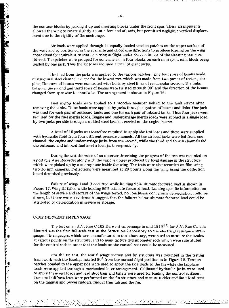
Air loads were applied through 44 equally loaded tension patches on the upper surface ofthe wing and so positioned in the spanwise and chordwise directions to produce loading on the wingapproximately equivalent to that occurring in flight under the conditions of the stressing case con-sidered. The patches were grouped for convenience in four blocks on each semi-span, each block beingloaded by one jack. Thus the air loads required a total of eight jacks.
The 1( ad from the jacks was applied to the various patches using four rows of beams madeof structural steel channel except for the lowest row which was made from two pieces of rectangularpine. The rows of beams were connected with bolts by steel links of rectangular section, The linksbetween the second and third rows of beams were twisted through 900 and the direction of the beamschanged from spanwise to chordwise. The arrangement is shown in Figure 16.
Fuel inertia loads were applied to a wooden member bolted to the tank straps afterremoving the tanks. These loads were applied by jacks through a system of beams and links. One jack"was used for each pair of outboard tanks and one for each pair of inboard tanks. Thus four jacks wererequired for the fuel inertia loads. Engine and undercarriage inertia loads were applied as a single loadby two jacks per side through a welded steel bracket carried on the engine bearer.
A total of 16 jacks was therefore required to apply the test loads and these were suppliedwith hydraulic fluid from four different pressure channels. All the air load jacks were fed from onechannel, the engine and undercarriage jacks from the second, while the third and fourth channels fedth.. outboard and inboard fuel inertia load jacks respectively.
During the test the voice of an observer describing the progress of the test was recorded ona portable Wire Recorder along with the various noises produced by local damage in the structurewhich were picked up by a microphone inside the wing. The tests were also recorded on film usingtwo 16 mm cameras.. Deflections were measured at 20 points along the wing using the deflectionboard described previously.
Failure of wings I and II occurred while holding 95% ultimate factored load as shown inFigure 17.. Wing III failed while holding 85% ultimate factored load. Lacking specific information onthe length of service and storage of the wings tested, no conclusion concerning deterioration could bediawn, but there was no evidence to suggest that the failures below ultimate factored load could beattributed to deterioration in service or storage.
C-102 DERWENT EMPENNAGE
The test on an A.V. Roe C-102 Derwent empennage in mid 19490 I for A.V. Roe CanadaLimited was the first full-scale test in the Structures Laboratory to use electrical resistance straingauges. These gauges, which were manufactured in the laboratory, were used to measure the strainsat various points on the structure, and to manufacture dynamometer rods which were substitutedfor the control rods in order that the ioads on the control rods could be measured.
For the fin test, the rear fuselage section and fin structure was mounted in the testingframework with the fuselage rotated 900 from the normal flight position as in Figure 18, Tensionpatches bonded to the upper side wcre used to apply the side loads to the fin while the tailplaneloads were applied through a mechanical le, er arrangement. Calibrated hydraulic jacks were usedto apply these Lest loads and ledd shot bags and billets were used for loading the control surfaces.Torsional stiffness tests were performed on the fin structure and manual rudder and limit load testson the manual and power rudders, rudder trim tab and the fin.

-7-
The tailplane was mounted parallel to the floor in an inverted position and the four forkeafittings for connecting the tailplane to the lower fin were used to secure the tailplane to the teststructure. Loading of the control surfaces was by means of lead shot bags and billets and hydrau!icjacks were used to load the tailplane structure through tension pads. Small hydraulic jacks ard tensionpatches were also used to load the trim tabs in the elevator limit load tests. A typical set-up is shownin Figure 19. Torsional stiffness tests were performed on the manual elevators and tailplane, and ihij.itload tests were performed on the manual and power elevators, trim tabs and tailplane. No f',Jures crindications of incipient failures were observed.
C-102 DERWENT MAINPLANE AND CENTRE FUSELAGE
The mainplane and centre section fuselage of the C-102 were tested in the laboratory in"mid 1950 again for A.V. Roe Canada Limited(16 ). The specimen consisted of the primary mainplanestructure, and the fuselage centre section terminating with the transport joints. Fuselage extensions,
* each consisting of one bay of normal fuselage structure terminating in a short strengthened section,were fitted to the fuselage, and bolted to a rigid welded-steel ring at each end; rings were secured attwo transverse pin points, by vertical links connected to the rigid steel supporting structure. Fore andaft movement of the fuselage section was limited by ties between the pins in the forward ring and abemn in the laboratory floor some distance forward of the main restraint. Figure 20 shows the testrig at different stages in the test programme.
Simulated air loads were applied to the upper surface ox the wing by means of the usualcalibrated hydraulic jacks through links and beams to tension patches. Concentrated loads wereapplied by additicnal hydraulic jacks through suitable linkages to fittings on the wing structure atspecified locations. About 850 strain gauges were applied to the structure, and selected groups ofthem were recorded for the various tests.
The torsional stiffness of the starboard wing was measured and then two limit load testswere performed for a specified loading and flight condition. Several tests of the integral fuel tanksunder various flight conditions were also completed. When these proved satisfactory, the specimen
.- was tested to destruction under the same conditions as for the flight limit load test. The centre section
.* wing collapsed at 103% ultimate factored load,
TEXAN T6 MAINPLANE
After inflight wing failures of two Texan T6 aircraft in 1951, the RCAF requested thelaboratory to verify the strength of the mainplane' 17) In view of the urgency, an initial test was madeusing deadweights (lead shot bags), in the manner described earlier for the Harvard wings(3), in both
." the high and low angle of attack conditions. From this test it was concluded that the used wing whichwas tested satisfied the relevant statutory proof load requirements. The wing was then tested withhydraulic loading using tension patches and whiffletrees. The wing supported 120% ultimate factoredload but the upper surface collapsed about 21 inches outboard of the transport joint as the loadapproached 125%. However, this did not duplicate the inflight failure and it was therefore suggestedthat the possibility of fatigue failure should be examined.
STATIC TESTS ON C-100
Over a period of seven years starting in 1950, full-scale static tests were performed onvarious components of the A.V. Roe C-100 aircraft, all using similar loading and measuring systemswith small improvements from time to time.
The status of the National Aeronautical Establishment (NAE) with rcipect to the structuraldevelopment of the CF-100 aircraft has never been clearly defined, but nearly all the test work was"carried out on the basis of technical and financial arrangements concerted directly between A.V. Roe
-* and NAE. The RCAF was apprised of all NAE operations, invited to witness all tests, and providedwith NAE reports containing the test results.
*" - . .""".• -.• ." "" " " . " *

0I -8-
In the case of all tests directly financed by A.V., Roe, the responsibility for the nature of"the test, the magnitude and disposition of the applied loads, and the specification of the requiredmeasurements was taken by A.V. Roe. The NAE accepted responsibility solely for the methods andprocedure of testing, and for the accuracy of all the applied loads and measurements.
"In general, the NAE was not provided with, and was not able to obtain, sufficient relevantfundamental data to check the appropriateness of the test made, nor the validity of the test loads anddistribution. The tests were therefore all conducted on the basis that the data supplied by Avro werecorrect, but a caveat was sent to the RCAF explaining these circumstances.
The first compopent tested in early 1950 was a tailplaie(18). This was the first test in whichthe newly developed 200-channel strain indicator was used (Figure 21). The test set-up is shown inFigure 22. A proof load test of an outer wing in the same year(19) ized two slightly different loadingtechniques. Loads at the leading edge were applied "hrough sheets of aluminum alloy riveted to theleading edge structure and loads at the end ribs were applied by underwing contour beams throughrubber pads cemented to the lower beam., These arrangements are shown in Figure 23.
An empennage and rear fuselage strength test(20 ) used "compression pads" on one side ofthe fin in addition to tension pads on the other side to apply side loads to the fin. The coml-ressionpads were connected to the beam system by tension links passing through reinforced holes in thestructure. The arrangement for this test is shown in Figure 24.
-4
A further four outer wing tests were performed in 1950 and early 1951(21-24). The last ofthese saw the introduction of load cells for measuring the loads rather than relying on pressure gauges.and calibrated hydraulic jacks., This was because the nature of the required load distribution entailerd"hydraulics jacks loading in opposition, which would make control of the loading between incrern.ents""ery difficult, and since the direction of travel of the jack position could va-y from increment toincrement, the calibrations would not be reliable.. The load cells, called "weigh-bars" were manu-factured in the laboratory and consisted of a berylium-copper bar fitted with NRC bonded resistancewire strain gauges whose output was read on meters located at each jack pressure control point.
A further tailplane test was conducted in 1952(25) and compression patches were againused, this time to provide a couple at the elevator hinge. This is shown it, Figure 25 which also showsa close-up of the load cell that was used.
Over the next four years four more outer wings were tested after various modifications(2 6 29 ).Most of these tests included the effect of fuel pressurization. This was achieved by blanking thenormal tank interconnections and connecting them externally in groups; pressures were increased asrequired by introducing fuel under pressure from a common source through separate control valvesand were read on individual Bourdon gauges.
REPEATED LOAD TEST ON CF-100 WING PANELS
The first fatigue test of an aircraft structure conducted in the Structures laboratory of NAEwas a manually repeated limit load test on a CF-100 Mark I outer wing panel in early 1952(30). Thiswing was one of three superfluou,, Mark I outer wings supplied by A.V, Roe, but the tests were not"requested or financed by them, but were undertaken by NAF partly as a fact-finding operation for"research purposes, and partly because of some concern regarding the adoption of a 9g ultimate loadfactor for the aircraft. The general arrangement and linkage was similar to that described inReference (23). However, rather than using two separately operated jacks for applying the test loads,all loading was derived from a single source of hydraulic pressure by modifying the outboard loadinglinkage. Load was applied manually to a maximum of 77% of the ultimate load determined in aprevious test-2 1); this was equivalent to a 6.5g load. A complete cycle of loading when records werenot taken took place in about two minutes.
0

- - - - - -' - - -- 77. 1.- 7 7 7 77
4 -9-
The wing began to develop serious damage after 82 cycles of load and it was expected that,in the absence of remedial action, the wing would have failed after 100 cycles in a manner similar tothe mode of fracture observed in the static test. However, it was known that this mode of failure wasessentially a skin instability phenomenon coupled with inadequate strength and stability of theforward ribs and rib attachments, and that the Mark I modified and Mark II wings represented animprovement in this respect. For these reasons, it was decided to effect some degree of repair andstabilization to the ribs and attachments in the hope that failure in this mode could be postponeduntil some more fundamental mode of failure had supervened.
The first primary structural failure apart from those occurring in the forward ribs was firstnoticed after 720 cycles and occurred at the main spar lower transport joint fitting. The repair schemeadopted for the ribs was successful insofar as final failure of the wing took place in a diffe;&..t a' :nfrom the static mode, but the final failure was not considered to have been unaffected by hie ribfailure. The wing withstood a total of 1543 applications of the maximum test load, and ignoringconsiderations of possible service loading and the behaviour of the forward rib structure, thisendurance was considered to represent a satisfactory fatigue resistance for the applied load range.
The two other wings were tested at 1.5g and 3g but the results do not appear to have beenreported in detail. However, in an unreferenced memorandum it was stated that while the results ofthe work were still being analysed, it was considered that there was no immediate danger of fatiguefailures in the outer wings of in-service CF-100 aircraft.
The first automatic fatigue test of an aircraft structure carried out in the laboratory was arepeated limit load (6.67g) test on a C-100 Mark 3 outer wing for A.V. Roe (Canada) Limited in1953(31). The specimen was mounted on the tubular steel framework as for the static tests, and thespecified shear, torque and bending moments were achieved by the use of two jack systems fed froma common hydraulic source., Load, renresenting wing lift, less structural and fuel inertia, was appliedby four overhead hydraulic jacks, arranged in parallel, and distributed through a system of beams andlinks to tension patches bonded to the upper surface, aluminum alloy sheets riveted to the leadingedge flap at the intermediate rib stations, and underwing contour beams at ribs 1 and 10. A secondaryload, applied by a pair of smaller jacks below the wing and distributed through a system of beams andlinks to contour blocks fitted in the upper dive brake trough and a single tension patch on the lowersurface, provided the desired modification of the primary load, particularly with respect to torque.The test arrangement is shown in Figure 26.
The automatic loading system, ,.hown schematically in Figure 27, consisted of twodeadweight pressure controllers for the upper and lower pressure limits, the movements of whichactuated micro-switches and a relay, operating solenoid valves which alternately connected the jacksto a high pressure source and to a reservoir. The measurement of the jack loads was by means ofstrain gauged dynamometers so that corrections to the deadweights could be made as required "to
* compensate for changes in load due to phenomena such as oil temperature variations. The rate ofloading was limited to about 2 cycles per minute in order to maintain the desired accuracy of loading.
The first two cycles were applied manually in order to record strain readings before"commencing a'itomatic cycling of load, Subsequent manual loadings were carried out at 76, 1191,
1279 and 1471 cycles to investigate any differences in strain records resulting from damage. Although*i loud noises were heard as early as cycle 759 no damage was observed until a crack in the lower skin
"was observed at cycle 1218. The main spar boom failed completely after 1524 cycles and the test washalted.
MENTOR WING
In 1955 static strength tests on two specimens of the left hand outer wing of a Mentoraircraft were carried out for the Directorate of Flight Safety as part of an investigation into the cause"of wing failure during a flying manoeuvre of an RCAF aircraft( 32 ). The wing specimen was mounted
... on a steel plate carried by an Li-frame of steel beam construction and loaded in the normal manner to
N . -. .. .. ... . . . -. . .- . - .. -.o .-. . -. . *o -. -. . . - .-. - . .- .. -. ', -.. -. • . . . . - . . .
-10-
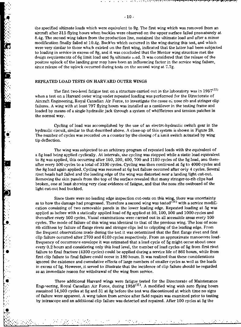
the specified ultimate loads which were equivalent to 9g. The first wing which was removed from anaircraft after 315 flying hours when buckles were observed on the upper surface failed prenriaturely at8.4g. The second wing taken from the production line, sustained the ultimate load and after a minor"modification finally failed at 10.4g. Buckles which occurred in the wing during this test, and whichwere very similar to those which existed on the first wing, indicated that the latter had been subjectedto loading in service in excess of 8g, and it was concluded that the Mentor wing structure met thedesign requirements of 6g limit load and 9g ultimate i.oad, It was considered that the release of thepositive uplock of the landing gear may have been an influencing factor in the service wing failure,since release of the uplock occurred during tests on the second wing at 7.7g.
"REPEATED LOAD TESTS ON HARVARD OUTER WINGS
"The first two-level fatigue test on a structure carried out in the laboratory was ih 1957(33)when a test on a Harvard outer wing under repeated loading was performed for the Directorate ofAircraft Engineering, Royal Canadian Air Force, to investigate the cause oi nose rib and stringer clipfailures. A wing with at least 797 flying hours was installed as a cantilever in the testing frame and
- - loaded by means of a single hydraulic jack through a system of whiffletrees and tension patches in* the normal way.
Cycling of load was accomplished by the use of an electro-hydraulic switch gear in thehydraulic circuit, similar to that described above. A close-up of this system is shown in Figure 28.
* The number of cycles was reccrded on a counter by the closing of a limit switch actuated by wingtip deflection.
The wing was subjected to an arbitrary program of repeated loads with the equivalent ofa 5g load being applied cyclically. At intervals, the cycling was stopped while a static load equivalentto 8g was applied, this occurring after 100, 200, 400, 700 and 1100 cycles of the 5g load, ana there-after every 500 cycles to a total of 3100 cycles. Cycling was then contioued at 5g to 4000 cycles andthe 8g load again applied. Cycling was resumed at 6g but failure occurred after orly 4 cycles. Severalrivet heads had failed and the leading edge of the wing was distorted near a landing light cut-out.
•" Removing the skin panels from the top of the surface revealed th.at many stringer-to-rib clips had
broken, one at least showing very clear evidence of fatigue, and that the nose ribs outboard of thelight cut-out had buckled.
Since there were no leading edge inspection cut-outs on this wing, there was uncertaintyas to how the damage had progressed. Therefore a second wing was tested(34) with a service modifi-cation consisting of two removable panels in the lower leading edge. Repeated loading at 5g wasapplied as before with a statically applied load of 8g applied at 50, 100, 500 and 1000 cycles andthereafter every 500 cycles.. Visual examinations were carried out in all accessible areas every 100
*0 cycles. The mode of failure of this wing was identical to that of the previous wing. The loss of nose- rib stiffness by failure of flange rivets and stringer clipE led to crippling of the leading edge. From
the frequent observations made during the test it was determined that the first flange rivet and first•. -clip failure occurred after 2700 and 6100 cycles respectively. From an approximate manoeuvre load-
frequency of occurrence envelope it was estimated that a load cycle of 5g might occur about onceevery 0.2 hours and considering only this load level, the number of load cycles of 5g from first rivetfailure to final fracture (4300 cycles) could be applied during a service life of 860 hours, while fromfirst clip failure to final failure could occur in 180 hours. It was realized that these considerationsignored the existence and cumulative effects of large numbers of smaller cycles as well as the loadsin excess of 5g. However, it served to illustrate that the incidence of clip failure should be regardedas an immediate reason for withdrawal of the wing from service.
* Three additional Harvard wings were fatigue tested for the Directorate of MaintenanceEngi-leering, Royal Canadian Air Force, during 1958 35). A modified wing with zero flying hourssustained 14,500 cycles at 5g and 31 at 8g before the test was discontinued at which time no signsof failure were apparent. A wing taken from service after field repairs was examined prior to testingby intrascope and an additional clip failure was detected and repaired. After 100 cycles at 5g the

-4 1Z -
leading edge failed at 7.6g during the application of the static 8g load. The last specimen, also takenfrom service after field repairs sastained 2000 cycles of 5g load, followed by 3500 cycles at + 5g,-2-l/2g, 500 cycles at +6g, -3g and 3500 cycles at 6g before failure occurred. However, in this testrepairs were made in the laboratory as the test progressed. It was noted that the interpretation of thelaboratory tests was restricted owing to a lack of information concerning the connection be weenlaboratory results and field effects.
REPEATED LOAD TEST ON CF-100 OUTER WING
A repeated limit load fatigue te.st of a CF-100 Mark 3 outer wing removed from an aircraftwhich had completed 1000 hours total flying time was performed for Avro Aircraft Limited in1959(36). This was a repeat of the test performed in 1953(31D, and consisted of applying repeatedlimit loads (6.67g) at a frequency of about 1-1/2 cycles per minute. A crack was first observed in thelower skin forward of the main spar after 1954 cycles and final failure resulted from fracture of themain spar tension boom after 2467 cycles. This failure was across the section of the most outboardbolt of the transport joint pick-up fitting, and duplicated the final failure of the previous Mark 3 wingfatigue test. It was suggested that the appearance of a crack in the lower forward skin area could beused as a fatigue indicator. In the previous Mark 3 fatigue test more than 300 cycles were completedbetween the appearance of the crack (in the same area) and final failure, and in this test more than500 cycles were completed during the same interval. It was therefore considered safe to concludethat there would be an adequate time margin between first crack and final catastrophic failure.
SABRE 5 HORIZONTAL STABILIZERS
As part of the investigation into an accident of a Sabre 5 aircraft, the laboracory conductedrepeated load tests on two Sabre 5 horizontal stabilizers for the Directorate of Flight Safety, RoyalCanadian Air Force, in 196107), One stabilizer tested was rebuilt to new standard by Canadair Limitedwith no subsequent flying hours, while the second was removed from an aircraft after 746 flyinghours. A special attachment was designed so that the stabilizer (less elevator) could be secured withbolts through the jack attachment in the front spar centre beam and the pivots on the rear spar centrebeam. Two load conditions were used, a resultant up-load at 6.95g resulting from a manoeuvre con-dition with dive brakes at 500 and a resultant down load at 7.33g resulting from a balance condition.Up and down loads were applied alternately as consecutive half cycles. The up and down loads were
"* applied through two separate hydraulic jacks, distributed through beam and link systems to tensionpatches over and under the stabilizer at the first four ribs. Load was measured via strain-gaugedberyllium-copper dynamometers between the final beam and the loading jack and cycling was con-"trolled automatically through an electro-hydraulic control system at about 3 cycles per minute. Thiswas similar to that described previously but consisted of two deadweight pressure r ontrollers, one onthe "up" load jack line and one on the "down" load jack line.
Neither stabilizer showed any sign of damage after 3000 cycles at 100% limit load and sothey were then tested to destruction at 125% limit load. The used stabilizer showed evidence ofcracking after 1500 cycles and the front spar centre beam failed after 3374 cycles. The first crackin the rebuilt stabilizer was observed after 1355 cycles and the rear spar centre beam failed in theweb after 4320 cycles.
FOUND BROTHERS FBA-2 AIKFRAME
In 1962 the laboratory conducted an extensive series of static tests on the airframe of aFound Brothers FBA-2 aircraft03 8 ). These were performed for the company with a view to satisfyingairworthiness requirements prior to certification. Examination of the centre-section pick-up attach-ment prior to testing showed that its support would be unrealistic if a rigid frame section wereemployed and therefore the fuselage frame section was included in the wing-holding system. The
entire specimen then consisted of the port and starboard wings, together with the centre-section and

-12-
tubular fuselage frame, excluding wing tip fairings, flaps and ailerons. Additional triangulated framesof light steel sections were attached to the forward and aft faces of the centre fuselage in order toapply the necessary nose and tail loads required for balance. The specimen was mounted in a freely-suspended condition in the gallows frames, being supported from the overhead beams by means ofwhiffletrees between hydraulic jacks on the frame and tension patches bonded to the upper wingsurface. Down loads were applied to the fuselage floor by means of rods and plates leading to afuselage whiffletree system.. NosE ind tail loads were applied at their relevant angles to the fuselage
"* datum line by flat steel links connected to hydraulic jacks located on the centre-line of the aircraftin the base of the test rig. The test arrangement is shown in Figure 29.,
Deflection measurements were made using deflection wires and boards, and strainmeasurements were made using about 300 strain gauges. Loads were measured with strain-gaugedberyllium-copper dynamometers. The test loads represented the best practical compromise betweenthe shear, bending torque and balance loads presented by the analytical desigii loads, and theirderivation was included as an appendix to the report.
In initial tests the starboard outer panel failed at 97% ultimate design load, but aftermodification was found capable uf carrying 100% of the ultimate design load for thc symmetricloading case. In the asymmetric loading case, a bolt in the port transport joint attachment failed after10 seconds at 100% ultimate design load.
r Drop tests on the main undercarriage of the same aircraft were described in a separate•- report( 3 9 ).
FULL SCALE FATIGUE TEST OF CF-100 AIRCRAFT
In 1963 'le Iirectorate of Aircraft Engineering, Royal Canadian Air Force, requested theStructures Laboratory to perform a full-scale fatigue test on a CF-100 aircraft to determine whetherthe then accepted service life of 2800 hours could safely be exceeded(4°). An aircraft with a totalflying time of 129 hours was removed from storage and made available for the test. It was a hybridversion with the extended Mark 5 tail and Mark 4 wings but was considered representative of theaircraft then in service.. The complete tail section aft of the tail transport joint was removed fortesting as a separate unit, ard to facilitate rigging and inspection, the engines and nacelles, wing fuelceihs, ailerons, flaps, various Cairings and non-structural skinning, nose undercarriage and main under-carriage wheels and brakes were removed.
Wing-Fuselage Test
A flight load spectrum was determined fiom the only available ffight data which consistedof 2783 hours of accelerometer data from eight aircraft in various squadrons. Since there were con-siderable variations between individual aircraft, an upper bound to the data was used except that afew exceptionai rpecords were omitted as being non-representative. No negative flight accelerationswere available nor loads due to ground manoeuvring or landing. The former two were considered tohave negligible effect while landing loads were accounted for by considering the maximum wing loadreversal which occurred on ground when the fu?] tanks were refilled.
The test load history derived from this spectrum was applied in a programmed scheme inwhich the load level was progressively increased and decreased in a continuous manner in repeatedblocks to give the correct distribution of load level and frequency. Constant amplitude testing at themost damaging level (from a Miner analysis) was rejected as being only able to show the mode offailure pertinent to the selected load level. In addition, the interpretation of the test would also bedependent on the validity of the cumulative damage hypothesis used. Random load applicationaccording to the load and frequency distribution was rejected both because of i't complexity at thattime and because of a concern over interpretation of a test result which might be influenced by theparticular random sequence used in the test.

A -13-
Since the shortest unfactored predicted life for the CF-100 was 4470 hours, the blocklength was made 50 hours and the lower and upper truncation levels set more or less arbitrarily at 2gand 6g respectively, The upper load level, whicn corresponded to 82% of design limit toad was applied"once in each 50 hour block. Down loads equivalent to the maximum fuel weight were applied ingroups of 25 cycles at the end of each 50 hour block. It was recognized that the influence of thes,down loads would be more severe if they were uniformly distributed throughout the loading rather"than lumped together, but the application of these loads re,,ouir *o+ ,- . . change, sincethe weight of the aircraft had to be transferred from the wings to the landing gear. Distribution of"these loads would therefore have been uneconomical in terms of test duration. Air loads and inertiarelief due to wing and fuel weight were calculated for the maximum load factor of 6.0 and the groundloads calculated fcr the static case at maximum gross take-off weight with a full fuel load in each wing
". •and tip tank.
The prime consideration in applying the test loads was to ensure that the vertical shear andspanwise bending moment di'tributions on the wing were correct. The wing-fuselage combination was"suspended in the structural test frame, effectively from a point on each wing corresponding to thecentre of lift. through a whiffletree arrangement connected to a number of loadiihg pads. These weresecured to the upper skin surface at the intersection of the ribs and the front and main spars, andwere lightly cemented to the skin and held in place by bolts passing through the wing. Good agrep-ment was obtained between theoretical and applied shear and bending moments but the torque aboutthe main spar was only 60% of the required value since this would have required a marked deviationfrom the theoretical requirements for the fuselage load distribution to maintain equilibrium.
Distributed loads were applied along the fuselage through a series of beams and links by fourhydraulic jacks, one applying the balance of the required nose inertia, one the engine inertia, one thebalance of the aft section and tail section inertia and the fourth balancing the test weight of the centresection and any small increment necessary to maintain equilibrium., The inertia loads of the centresection were considered balanced by the lift attributed to this section. Attachment to the fuselage wasthrough jacking pads, riveted straps, engine bearers, special attachments riveted to tne fuselage former,and the tail cone attachments. A dummy strut secured between the nose undercarriage pivot centreand thc ground, in addition to providing nose gear reaction in the landing case, maintained pitchcontrol by reacting any small imbalance in the system as the wings deflected under load.
The static ground case was achieved by raising the complete aircraft by means of hydraulicjacks pushing on the main undeicarriage legs so that the wing was relieved of all up-loads. Fuselagedown loads were applied by the same system as for the flight loads and wing down loads were thenapplied by two jacks connected to a dead weight through underwing whiffletree systems and padsattached to ihe lower skin surfaces similar to the upper ones. The final link between the jack and thedeadweight was designed with free movement to ensure that the weight would not be picked upduring application of flight loads. Figures 30 and 31 show front and side elevations respectively of the
*O basic test frame and loading systems. Figure 32 is a photograph of the complete test arrangement.
The load control system consisted of four basic units, a function generator, regulated d.c,reference voltage and discriminator, and programmable frequency control and amplitude controlpotentiometers. Programs were etched on conductive paper, the etched line dividing the surface intotwo electrically isolated areas, The paper was attached to a rotating drum and an electrostatic probeconnected to a potentiometer followed the line to give an output proportional to the position of theline. The function generator generated a sine wave function in which the base frequency was variedby the control potentiometer so that the small cycles could be applied faster than the large ones.This output was then modified by a bias voltage to shift the mean to the desired level and then furthermodified by the Lmplitude control potentiometers which resulted in an output amplitude correspond-ing to the desired load history. This outpu was then divided by proportioning attenuators so that
*g the sigrnal being fed into each of the three servo-controllers was in direct proportion to the load- requirements of each system. The load applied to the centre section lift system was maintained at a
constant value throughout the test by a set-point adjustment of the corresponding servo control unit.The frequency was such that a complete 50 hour load block consisting of 454 cycles was applied in2-1/4 hours.

4 -14-
The first block uf automatic spectrur,1 loading was comnleted on May 28, 1964 and"continued ,ntil the 86th b!ock (4300 equivalent flight notuisl. During this block, a 2-1/2 inch longcrack was detected in a iain gear door beam biecket (a secondat-, str.acture) and it was establishedthat similar cracKs had occurred on several service aircraft., The area was repaired but the repair failedafter a few blocks and after further unsuccessful repairs tf..- rate of crack prpagation eventuallydecreased so that by the end cf the test it was virtually dormant. During the rew:ander of the testup to block 400 kthe original target of 20,000 equivalent flight hours) a rurnbEr of minor failaresoccurred but only one was ,onsidexed of any c3nsequence., This was a failure of some bolts attachingthe lower wing skin to t'he spa- near the port oMter wi.1g transport ic -, and those were tnen replaced"eve-y 100 equivalent flight hours (one major inspc'-tion period).
During block 403 small cracks were observed in the steel fingers o" i:e lo'ver starboard wng- transport joint fittings and were subs.2quently observed in the other wing tr:_nsvort joint fittings. The
test was continued witho it any attempt at repai: since ',my repair would L.-, a very majoi undertaking- -" and it had already been demonstrated that tl'e structure ,- an adequate life for the known RCAF
requirement. Final catastrophic failure of the port lower transport joint occurred at the maximumload during block 483 (24.150 equivalent flight hours),
Using a safety factor of 5.0, it was concluded that under the specified load'ng conditionsthe safe fatiguc life of the Ct? 100 aircraft was approximately 4830 hours, but it was recommendedthat a continuing program of load monitoring be carried out on service aircraft in order to validatethe load spectrum used ir. the test programme.
Horizontal Stabilizer Test
For a given mano,:uvre the pi'ot-induced loads on the stabilizer can vary by a substantialamount depending upon the rate of appl.cation of control angle, Since there was no statistictl dataon this distribution it was decided si-ply to use the values of maximum total symmetrical loaddeteormivd in a pi'eviou, study of the symmetric tail loads of this aircraft(4 -), divided by the acceler-
- atior increment of the manoeuvre., This gave an average value of tail load per g of 1000 lbf. For eachmanoeuvre initiated by ' negative tail load it was conservatively assumed that there would be an
" equal and opposite tail load to terminate the manoeuvre. With the tailplane mounted on the fin, anyrIing momer , applied to, it must be carried by the fin., Therefore, since in addition there was somedoubt as to the fatigue resistance of the tail c-ne tniisport joints with respect to asymmetric loads,the tailplane was subjected to both symmetric and asymmetric loads. It was decided that eachsymmetric load application be followed by an equal asymmetric load giving a loading srquence -
-. symmetric up, ,:symmetric port down, symmetric down, and asy.nmetric starboard down as shown inFigure 33. The-e was no direct corrf spondence between the tailplane flight and test loads other thanthe grneral form of the load spectrum described previously. The emphasis on the tail was thereforeto determine the mode of iailure rather than the safe life.
The complete tail se. tior, less the top portion of the fin, the ridder, tail cone and elevatorswas attached to a tubular stee! test frant.e at the four transport joint fittings with the fin veitical. Aconstant down load equal to the required r _dximurn (5000 lbf) was maintained by a deadweightconnected to the lower lo-iding system. The Irw -ing ja.cl:s, secured in universal mounting: w-1hin thegallows frame., were then used to apply a net up-lo.d through the upper loading system capable ofvarybig betweeta zero and twice tie deadweight giving an effecti-e ret load on th.e stabilizer va mingbeuween -5000 lof (down) and + 5000 lbf (up). Corrections wpre, of course, made for the tare weightsof the stabilizer and loading ý;,stems. The loading systems consisted of an upper and lower whiffletree connected to pads lightly connected to the skin surfaces and held in place by bolts passingthrough the stabilizer. Figures 34 and 35 show reax and side elevations respectively oi the basic testframe and loading systems. Figure 36 is a photograph of the complete test arrangement.
The load control system was similar to that for the wing-fuselage test except that thefrequency was kept constant and two additional programmable amplitude controllers were used, one
"" for each side. The final output to each servo control unit was proportiat.al to the product of theprimary auc. secondary amplitude signals as shown in Figure 37.

- 15-
During the greater part of the fatigue test, only m;nor damage occurred, usually rivetfailures. After completion of 300 blocks (12,000 equivalent 'light hours) repairs were made sincethese would normally be made on service aircraft during overhaul. Similar repairs were made after16,300 equivalent flight hours and a very thorough inspection carried out at 20,230 equivalent flighthours found no major defects. Since there were some doubts as to t":2 validity of the teet loads andthe test had to continue until a major failure had occurred, the symmetric loads were increasedarbitrarily by 50%. After an additional 500 blocks (a total of 40,230 equivalent flight hours) therewas still only minor damage. Testing was then continued at constant amplitude at the highest loadthe test rig was capable of (± 7.5g). After 21,800 of these cycles, a 2 inch long crack was observed inthe starboard angle of a former, After a total of 42,700 constant amplitude cycles, the crack was stillpropagating slowly and had been present for a sufficient length of time to ensure tlhat it could bedetected in service prior to any major failure. The test was therefore discontinued.
FULL SCALE FATIGUE TEST OF CT-114 TUTOR WING
In 1968 the Directorate of Aeronautical Engineering and Simulators (DAES), CanadianForces Headquarters, requested the assistance of the Structures Laboratory in resolving a prematurecracking problen" in the Canadair CL-41 Tutor aircraft(4 2 ). The aircraft had been designed and tested
' to meet the requirements of U.S. military specification MIL-A-8866( 4 3 ) and had been tested to anequivalent service life of 40,000 houis with no sigrificant failures. However, 63 cracks had beenreported in the upper spar caps of the 48 aircraft in service, the first cracks being found in service
* aircraft at lives ranging from 900 to 1700 flying hours. Similar cracks in the fatigue test airframewere estimated (then) to have developed shortly before the completion of the 40,000 hour test. Theloca. 'on of the cracks was also disturbing, since thc loading on the upper element of the main sparwas presumably primarily compressive, whereas fatigue is usually associated with tensile stresses.
After reviewing the original fatigue Lest, only two possible question areas arose. One wasthat Canadair used a low-high load application sequence rather than the then currently acceptedlo-hi-lo sequence, and the second was that 8.8g loads were included every 300 hours although theaircraft would n:ot encounter them that often.
It was therefore decided to measure the strains oear the area of interest on an instrumentedaircraft and pe-form a further fatigue test on the wing with a more representative spectrum. Inaddition, the upper spar caps were studied to check che metallurgical condition and residual stressleve's.
First Phase Fatigue Test - Trainer Role
The derived spectrum for the test1 4 4) was based on counting accelerometer data from the4 ,nore severe of two training bases. The loads were applied in a programmed sequence of progressively
inc'easing and then decreasing loads of the same general form as for the CF-100 test, with eachpositive load cycle being followed by the negative equivalent that had the sar ie frequency of occur-rence., Since it was considered that a minimum of 30 load blocks should be applied before failure toavoid block sizing effects, and cracks had been observed as low as at 800 hours, a block size of10 hours was chosen., Since during a typical 10 hour block only peak loads corresponding to 5.4 and
4 -0,55g were encountered, the missing more severe loads were applied manually at the end of a groupof five 10 hour blocks, so that all loads that were present in the load spectrum were applied duringtbl' course of 1000 equivalent test hours.. The truncation level was set at a level that was exceeded"100 times per flight hour, which resulted in 1000 cycles per 10 equivalent flight hours comparedwith the 145 applied by the manufacturer.
The test specimen consisted of the forward and centre fuselage sections less all majorrem :vable "tems, and both wings complete with main larding gear but less ailerons and flaps. Thefatigue set-up, shown in Figures 38 to 40, was based on the original Canadair test, but all loads otherthan those due to normal acceleration were omitted. In addition some whiffletrees were extendedso that only four actuators were required compared to the 43 of the original test. The complete test
.: .. ., • - . -. . - . : •. •- .- ,. . - - .- . -.. - -. . , . - - ..- -- . . .o .
-16-
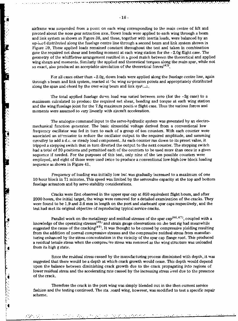
airframe was suspended from a point on each wing corresponding to the main centre of lift andpivoted about the nose gear retraction axis., Down loads were applied to each wing through a beamand link system as shown in Figure 38, and these, together with inertia loads, were balanced by anup-iuad distributed along the fuselage centre line through a second beam and link system shown inFigure 39., These applied loads remained constant throughout the test and taken in combinationgave the required net shear and bending moment at each wing station for the -2.Og flight case. Thegeometry of the whiffletree arrangement resulted in a good match between the theoretical and appliedwing shears and moments. Similarly the applied and theoretical torques along the main spar, while notso exact, also produced an acceptable simulation of the theoretical forces( 4 5).,
For all cases other than -2.0g, down loads were applied along the fuselage centre line, again"through a beam and link system, reacted at 'he wing su-pension points and appropriately distributedalong the span and chord by the over-wing beam and link syst:..-.
The total applied fuselage down load was varied between zero (for the -2g case) to amaximum calculated to producc the required net shear, bending and torque at each wing stationand the wing/fuselage joint for the 7.8g maximum positi,,e flight case. Thus the various forces andmoments were assumed to vary linearly with aircraft acceleration.
The analogue command input to the servo-hydraulic system was generated by an electro-mechanical function generator. The basic sinusoidal voltage derived from a conventional lowfrequency oscillator was fed in turn to each of a group of ten counters. With each counter wereassociated an attenuator to reduce the oscillator output to the required amplitude, and summingcircuitry to add a d.c. or steady load component. As each counter ran down to its preset value, ittripped a stepping switch that in turn diverted the output to the next counter. The stepping switchhad a total of 20 positions and permitted each of the counters to be used more than once in a givensequence if needed. For the purposes of this test, only nine of the ten possible counters wereemployed, and eight of those were used twice to produce a conventional low-high-low block loadingsequence as shown in Figure 41.,
Frequency of loading was initially low bu:, was gradually increased to a maximum of one10 hour block in 71 minutes., This speed was limited by the servovalve capacity at the top and bottomfuselage actuators and by servo stability considerations.
Cracks were first observed in the upper spar cap at 850 equivalent flight hours, and after2000 hours, the initial target, the wings were removed for a detailed examination of the cracks. Theywere found to be 1.9 and 3.6 mm in length on the port and starboard spar caps respectively, and thetest had met its original objective of reproducing typical service cracks.
Parallel work on the metallurgy and residual stresses of the spar cap(4 6 ,4 7 ), coupled with aknowledge of the operating stresses I8 • and strain gauge observations on bhe test rig had meanwhilesuggested the cause of the cracking(4 9 ),., It was thought to be caused by compressive yielding resultingfrom the addition of normal compressive stresses and the compressive residual stress from manufac-turing enhanced by the stress concentration in the vicinity of the spar cap flange root. This produceda residual tensile stress when the compreszive stress was removed as the wing structure was unloaded
*• from its high g state.
Since the residual stress caused by the manufacturing prc-cess diminished with depth, it wassuggested that there would be a depth at which crack growth would cease. This depth would dependupon the balance between diminishing crack growth due to the crack propagating into regions oflower residual stress and the accelerating rate caused by the increasing stress ievel due to the presenceof the crack.,
t Therefore the crack in the port wing was simply blended out in the then current servicefashion and the testing continued. The sta ioard wing, however, was modified to test a specific repairscheme.
I-"
..- --

-17-
The wings were removed again for inspection at 4000, 4600 (port only), 6000 and 8000hours and at this last inspection cracks were observed to have reappeared on the port wing upperspar cap. They were very small, however, and no modifications were performed.
Phase nne testing was halted in April 1971 at 30,000 equivalent flight hours (in the trainingrole). A post test inspection revealed no significant damage.
Secoi d Phase Fatigue Test - Snowbird Role
In developing the original test spectrum it had been assumed that the aerobatic role thaithe Tutor was used for at that time, the Golden Centennaires, would not continue. However, althoughthe Centennaires disappeared they were succeeded by another aerobatic display team, the Snowbirds.The spectrum for this role was similar to that for the trainer role in all respects except the frequencyof high g manoeuvres and fatigue damage calculations showed that the Snowbird role was 12 timesmore dam:iging than the trainer role.
Since the fatigue life of the aircraft in this role could be consumed in the foreseeablefuture, it was decided in November 1975 to resume the Tutor fatigue test(42). Because of restrictedmanpower, it was necessary to shorten the test and rather than delete the very numerous low loadsfrom the test it was decided to alter the loads spectrum to correspond to the Snowbird role. It wasrecognized that the resulting test life would be a combination of the two roles which might poseproblems of interpretation. It was anticipated, however, that the test would disclose the mode offailure and so Irovide guidance for scheduling inspections and other precautions to ensure the flightsafety of the aircraft.
The test spectrum was based on counting accelerometer data that had been accumulatedfrom seven Snowbirds and was defined in twenty steps, with a truncation level of 2.15g comparedwith 1.93g of the first phase. However, in order to speed up the test, after 7000 equivalent Snowbirdhours, the last two levels were omitted resulting in a truncation level of 2.77g. Since more than2.25 X 106 cycles of 2.5g or less had previously been applied in the first phase test, it was assumedtihat any fretting damage due to these loads had already occurred and so this t ru'acation was notunreasonable. Although the Snowbird role involves several manoeuvres at -3g, negative loads weretruncated at - 2g because of rig limitations. This was calculated to introduce an error of about 2.3% onthe fatigue life(50 ).
The fatigue test loading system used was the same as for the trainer role, but the methodof generating the loads w:•s quite different. The laboratory had acquired a PDP8e computer with 4Kof memory since the corn pletion of the trainer test and computer programs that had been developedpermitted a much greater versatility in the generation of load time histories. Since a random sequencewas considered to be more representative of actual service than any ordered sequence, the flight loadswere therefore randomly generated on a draw without replacement basis. The loads table was set upso that one complete block represented 100 equivalent flying hours, and each block was randomlygenerated. Thus; the sequence of loads in each block was different.
Because it is very difficult to determine crack propagation rates from post-fracture analysesot fractures produced during the course of a random sequence fatigue test, it was also decided to usea "marker block" in the load time history. This consisted of 64 constant amplitude cycles that wereapplied as the concludinp segment of each 100 equivalent flight hour block. The purpose of thismarker block was, after crack initiation, to provide an identifiable region of crack growth (markerband) within every 100 hour load block. By observing the spacing of successive marker bands it wouldthen be possible to determine crack growth rates. It is important to note that this marker sequencedid not alter the total damage content of the applied loads environment of the test structure, sincethese 64 cycles of loqd were extracted from the original load time history. It was recognized, however,that some of the sequential effects of these loads would be lost, but by choosing an intermediate loadlevel for the marker (2.221g ± 3.031g compared to a maximum of 3.116g ± 5.116g) this was thoughtto be minimal and far outweighed by the potential benefits.

.q -18-
Testing was resumed in early 1976 and at slightly in excess of 2100 Snowbird hours, acrack was found in the tang of the lower main spar cap at the port wing root. This crack eventuallypropagated until the lower main spar cap was completely severed at 10,200 Snowbird hours. Post-failure fractographic studies 51 ý disclosed that this crack had been present since the late stages of thephase one test, but was not discovered at that time. Once discovered, the crack was readily observablevisually, by ultrasonics and by dye penetrant techniques.
At 1500 Snowbird hours, a similar crack was found on the starboard wing. Because ofits later initiation and the general slow initial crack propagation rates, this crack did not extend tocatastrophic dimensions by the end of the test.
The conclusion of the test came when the port wing main spar separated at 10,200 Snowbirdhours, and the rear spar failed simultaneously due to partial fatigue damage as well as to the suddenoverload when the main spar support was lost. This failure, which occurred at the spar fuselage joint,was not detected during the course of the test.
The main spar top flange cracks that generated the initial fatigue life concern did notpropagate further during this test.
FULL SCALE FATIGUE TEST OF CS2F TRACKER WING
In the mid seventies, a review by the Canadian Forces (CF) indicated that the Grummani° CS2F Tracker aircraft could continue in its maritime reconnaissance role until the mid nineteen
nineties, This necessitated an audit of the aircraft structure to ensure that the airframe would remainairworthy for this period. A previous Tracker fatigue test performed in Japan for the United States"Navy was not considered relevant to the proposed Canadian operation because of differences inload spectra and difficulties with interpretation of the Japanese test. Therefore in June 1976 theDepartment of National Defence initiated the Tracker fatigue life extension program which involved(a) a full scale fatigue test of the Tracker wing, (b) a Grumman Aerospace Company review of theTracker fatigue analysis using CF mission and spectra data and (c) a limited damage tolerance assess-ment of the wing-to-fuselage attachment fittings, a lower wing lock fitting and a lower wing stringer.NAE was requested to perform the full scale fatigue test(52 ).
A large amount of flight data for the Tracker was available from counting accelerometers,Although it was representative of current usage it contained an unusually large nunber of 4g exceed-antes for a 3g limit design load aircraft. It was suspected that these high counts were either put oninadvertently during servicing of the accelerometer systems or occurred during rocket firing exercisesthat were carried out several times a year. The latter reason was not expected, however, and a laterload measurement program during rocket runs(5 3) confirmed this.. The decision was therefore madeto statistically edit the data to remove some of the high g counts. The data were assumed to have alog-normal distribution of counts about a prrticular 'g' level and only those periods of data for whichall the data fell within a band on either sde " the mean number of counts/hour were accepted.Several different band widths were tried and 3 final rejection criterion used was to remove allperiods of data which contained counts which fell outside 2.17 standard deviations from the mean,Using this technique approximately 10,000 hours of the 16,000 hours of data were retained'5 4 ).Since there were few measured ground load acceleratihns for the Canadian Tracker aircraft, theground loads spectrum was developed from the ESDU Data Item 75008.
The final flight load spectrum was split into a symmetric gust load spectrum and anon-symmetric manoeuvre load spectrum and these two spectra N. re then discretized into intervalsof 'g' containing inegral numbr.rs of cycles in each block of 100 flights. This resulted in 20 steps for
* the manoeuvre spectrum and 15 for the gust spectrum. A lower truncatikn level of 1.25g was usedfor the positive spectrum because a preliminary fatigue life estimate indicated that over 98% of thefatigue damage was caused by posit.ve accelerations above this level. An upper truncation level of3.84g was chosen using Maxwell's guideline(s5 ) that the maximum test Icad should be that which isseen approximately ten times in the life of the aircraft.
* * * - * - *7

-19-
The test loads were applied in blocks of 100 flights each representing 3.6 hours of serviceincluding taxi time, with a nominal testing flight time of 3.5 minutes. Each flight consisted of onepre-flight ground load, 49 manoeuvre cycles, two gust cycles and five post-flight ground cycles., Tocompose the first 99 flights, the 51 manoeuvre and gust cycles were randomly selected on a draw-without-replacement basis from a load table representing 360 hours of the derived spectrum. A similarrandom selection of six ground cycles completed the flight. The 100th flight was a marker blockconsisting of 51 constant amplitude cycles of between 1.878g and 0.912g. This marker flight was
applied to mark any developing fracture surfaces with recognizable bands for use during post-testfractographic analysis( 5 6 1. These marker cycles were not an addition to the load spectrum but were'saved' from the total applied load table.
The test specimen consisted of a complete aircraft less the nose section and tail section.Most electrical and electronic equipment and wiring was removed along with non-structural doorsand panels, flaps, ailerons, slats, wing tip fairings and pylons, wing fold actuators, landing gear andengines. It was suspended from a point oveL each wing in the standard NAE test frame via whiffle-trees as shown in Figure 42. Previous NAE full-scale tests used steel whiffletree loading systems.For this test, 6351-T6 aluminum channel was selected to save both weight and cost. The maximumoperating bending stress of 10,000 lbf/in2 used for designing previous steel whiffletrees was main-tained and the design procedure was experimentally verified(5 7. Chordwise load distribution wasobtained by using four inch wide contour boards running from the 15% to 57% chord at each rib ofthe outer wing. These contour boards were bonded to rubber patches and then bonded to the wingsurface; no through holes were used. The peak tensile stress between the contour board and the wing
* surface was limited to 20 lbf/in2 5 8 )
The Canadian Forces Directorate of Maritime Air provided the mission usage data and a* hypothetical average flight condition was defined. The net wing shears, bending moments and torques
for this condition were then calculated(5 9), Because the fatigue critical area was expected to be justoutboard of the wing fold, an effort was made to closely match the bending moments, shears andtorques in this region(60 ). This was achieved by six loading systems showa ii Figuies 43 to 46. Theunder fuselage system, Figure 43, simulates the fuselage inertia loads and matches the fuselage bendingmoments. The over fuselage system, Figure 44, simulates the centre wing inertia and air loads, and theground loads for the ground spectrum. The under nacelle system, Figures 44 and 45, simulates theengine inertia and ground loads.. The underwinig system, Figure 44, simulates the down loads on thewing and in conjunction with the overwing system applies the best fit shear, torque and bendingmoment distribution for the whole flight spectrum. The overwing system, Figures 44 and 46, reactsall the vertical loads applied to the aircraft and the nose pivot point reacts any fore and aft loadsapplied to the structure.,
Since only symmetrical loadLig cases were considered, only four command channels wererequired for the six servo-hydraulic actuators. The load level was randomly generated via the PDP8e
* computer used for the Tutor test, and then the command signals, which were all a simple linearfunction of the load level, were calculated for each channel. All of the actuators were fitted withload limiters (pressure relief valves) which protected the test article from being damaged by overload,They were also fitted with abort modules which allowed the actuators to be locked in pcsition in theevent of a problem with the system.. Pressure in the actuators could then be released manually byvalves in the abort modules.
Testing commenced on May 3, 1979 after an uneventful start-up. Sets of strain, load anddeflection data were recorded incrementally on a routine basis every 5000 flight hours and beforeremoval and after reinstallation of the outer wings which was generally every 15,000 hours. Numerous"cracks were observed and monitored during the course of the test at locations such as the nacellefirewall skin, spanwise stringers, door frame and fuselage frames. One area of interest was the search-
* light cut-out of the starboard wing. At flight 4600 a crack was discovered in a lower-skin doublerstrap at the cut-out, which was initially thought to be insignificant. However, at flight 4332 (15,595
. hours) a 'bang' redirected attention to this area, and an additional crack was found in the verticalleg of the front spar cap angle near the cut-out. The test was restarted and the crack grew rapidly toa captive nut attachment rivet hole. At this stage, it was decided, in liaison with DND and Grumman,

*@ -20-
to suspend testing until a repair had been made. The elapsed time from suspension of the test to the"* "finished installation of a Grumman developed repair scheme was apDroximately five months.
*.;. Subsequent inspections of this same area on the DND fleet of Tracker aircraft discovered three similar-"' cracks, except that they had not progressed into the spar cap angle., The same repair scheme was
applied to these aircraft.
The most prolific type of cracking observed during the test was that initiating in the lowerwing skin where an internal doubler was spotwelded to the new skin panels. The first crack was foundduring the 60,000 hour inspection, and once aware of the type of crack, inspection of other spotwelds resulted in the discovery of an additional 28 crack locations. Merging of several of these spotweld cracks on the right hand wing finally led to failure of the wing on application of the highest loadduring flight 32541 (117,144 simulated flying hours) on October 29, 1982. It was concluded 6 1) that,
-. using a safety factor of 4, the "safe-life" of the wing and its attachment to the fuselage for operational"aircraft under the current flying conditions was 29,000 hours. In addition, the growth of the lower
-.. skin cracks which led to final failure was slow enough to ensure a high probability of detection wellbefore any possibility of catastrophic failure.
CONCLUSIONS
Thirty-eight full scale tests of large aircraft structures have been performed in the Structures* Laboratory of NAE in the last 43 years. Table 1 provides a summary of these tests including the
agency for which the tests were performed, and it can be seen Lliat over 90% of them have beenperformed for or in support of the Department of National Defence and its predecessors.
In the early years the laboratory performed many original tests for DND that could not beperformed elsewhere in Canada and played a major role in performing structural tests on the CF-100.In later years, as the Canadian aircraft industry took on most of its own testing, the laboratory hasacted in a more supportive role, providing DND with an independent source of expertise and advice.,In addition, it has been able to provide alternative facilities for full scale fatigue testing of largestructures, which are not always available in industry on a continual basis.
The complexity of full scale aircraft structural testing has increased dramatically, however,over the past 40 years. Whereas the initial tests involved a few people for a few days, the last teston the Tracker took about 20 man years to set up and ran in the laboratory for over 3-1/2 years.Similarly, whereas the first tests were performed with rulers and lead shot bags, the last test involvedcomputer controlled servo hydraulic actuators. It is therefore clear that NAE must be prepared tomake major committments both in equipment and manpower if the laboratory is to maintain itspresence in this field.,
* REFERENCES
1. Reid, W.T., Static Tests of Moulded Wood Fuselages for Anson Aircraft.* Hiscocks, R.D. Report No., MM-41, National Research Council of Canada, Ottawa,
May 1941.,
2. Hiscocks, R.D, Static Test of Tiger Moth Wings by the Staff of the StructuresLaboratory.Report No. MM-42, National Research Council of Canada, Ottawa,January 1942.
3. Hiscocks, R.D. Static Test of Harvard II Wings.Report No. MM-44, National Research Council of Canada, Ottawa,
:- March 1942.

-21-
4. Hiscocks, R.D. Static Test of Hurricane Wing Panel for British PurchasingCox, W.J. Commission.
Report No. MM-68, National Research Council of Canada, Ottawa,August 1942.
5. Staff of Structures Description of Design, Construction and Testing of HarvardLaboratory Moulded Plywood Rear Fuselage and Tail Surfaces.
Report No. MM-101, National Research Council of Canada,Ottawa, May 1943.
6, Hiscocks, R.D., Static Test of Anson Mainplanes.Jelenick, M.D. Report No. MM-115, National Research Council of Canada,Cox, W.J. Ottawa, September 1943.
* 7. Jelenick, M.D. Static Test of Anson Tailplanes.Cox, W.J. Report No. MM-117, National Research Council of Canada,
Ottawa, Sentember 1943.,
8., Cox, W.J. Drop Test of Cornell Aircraft.Report No. MM-141, National Research Council of Canada,Ottawa, May 1944.
* 9. Cox, W.J. Static Test of Cornell Wing.Report No. MM-146, National Research Council of Canada,Ottawa, June 1944.
10. Cox, W.J. A Tailless Research Aircraft.Siddal, J.N. Aircraft Engineering, Vol. 21, No. 244, pp. 184-190, June 1949.
11. Proceedings of the 23rd Meeting of the Executive Committee ofthe Associate Committee on Aeronautical Research, NationalResearch Council of Canada, Ottawa, January 14, 1947.,
12., Haviland, J.K. NRL Hydraulic Static Testing Apparatus.McCaffrey, G.F.W. Report No. MM-213, National Research Council of Canada,
. -Ottawa, March 1949.
13. Belot, J.D. Static Tests on a Mosquito Wing Using Tension Pad Loading.
Report No. SM97, Council for Scientific and Industrial Research,"Melbourne, Australia, June 1947.
14. McCaffrey, G.F.W. Static Tests of Three Moscaito Wings.Report No. MM-215, National Research Council of Canada,Ottawa, May 1949.
"15.. McCaffrey, G.F.W., Empennage Tests of the C-102 Derwent Aircraft..* Thurston, F.R. Report No. MM-219, National Research Council of Canada,
Ottawa, March 1950.
16. McCaffrey, C F.W. Static Strength Tests of the Avro C-102 Mainplane and CentreThurston, F.R., Section Fuselage.
NAE Laboratory Report LR-1, National Research Council ofCanada, Ottawa, July 1951.
17.. Thurston, F.R., Static Strength of a Texan Outer Wing.Mentel, T.J. NAE Laboratory Report LR-15, National Research Council of
Canada, Ottawa, December 1951.,
[ ::': ::: ":* " - ... . -," - •- *- : . .- : " . - - -- " "- " " - . " • "• . .

-22-
* 18. McCaffrey, G.F.W. Static Testing of the Avro C-100 Tailplane with an Appendix on"Thurston, F.R. Vibration Test of the Unbroken Semi-Span.
Report No. MM-220, National Research Council of Canada,Ottawa, April 1950.
19. McCaffrey, G.FW. Proof Load Test of the Avro C-100 Left-Hand Outer Wing.Thurston, F.R. Report No. MM-224, National Research Council of Canada,
Ottawa, May 1950.
20. McCaffrey, G.F.W. Empennage and Rear Fuselage Strength Test of the A. V. RoeThurston, F.R., C-100.
Report No. MM-2.27, National Research Council of Canada,Ottawa, August 1950.,
21. McCaffrey, G.F.W., Static Strength Tests of the Modified Avro C-100 Left-HandThurston, F.R. Outer Wing.
Report No. MM-228. National Research Council of Canada,Ottawa, November 1950.
22.. McCaffrey, G.FW. Static Strength Test of the Avrc C-100 Right-Hand Outer Wing -
Thurston, F.R. C.P. Back Case, with Dive Loads.Report No. MM-229. National Research Council of Canada,
4 Ottawa, November 1950.
23. McCaffrey, G.F.W. Static Strength Tests of the Modified Avro C-100 Right-Han.2Thurston, F.R. Outer Wing - C.P. Forward Case.
Report No. MM-230, National Researuh Counc.' of Canada,Ottawa, January 1951.
24., McCaffrey, G.F.W., Static Strength Tests of the Avro C-100 Mark II Right HandWiebe, W. Outer Wing - C.P. Forward Case.
NAE Laboratory Report LR-37, National Research Council of"Canada, Ottawa, September 1952.
25., McCaffrey, G.F.W. Static Strength Tests of the C-100 Tailplane with SymmetricSchott, G.J, Down Load.
NAE Laboratory Report LR-39, National Research Council ofCanada, Ottawa, November 1952.
26. McCaffrey, G.F.W., Static Strength Tests of the Avro C-100 Mark III Right HandWiebe, W. Outer Wing.Schott, G.J. NAE Laboratory Report LR-55, National Research Council of
Canada, Ottawa, April 1953.
27. Wiebe, W. Structural Tests on Avro C-1O0 Mark 4 High Altitude VersionGwilt, S.R. Outer Wing..
Report No. MEI-86, National Research Council of Canada,- Ottawa, April 1955.
28. Gwilt, S.R. Structural Strength of the Avro C-100 Mark 6 Right-Hand OuterSewell, R.T., Wing.Wiebe, W.. NAE Laboratory Report LR-213, National Research Council of
Canada, Ottawa, November 1957.
29. Gwilt, S.R., Static Strength of an Avro CF-lO0 Mcrk 5 Starboard OuterSewell, R.T. Wing - Serial No. F3-713.
NAE Laboratory Report LR-216, National Research Council ofCanada, Ottawa, January 1958.
* .. '.-------- -. . .. .' -. -" - .. " ..- , .. . . - ..

- 23 -
30., Thurston, F.R. Preliminary Report on the Endurance of a CF-100 Mark I OuterMcCaffrey, G.F.W., Wing Panel Under Repeated Limit Loading.,
NAE Laboratory Memorandum ST-6, National Research Councilof Canada, Ottawa, May 1952.
S31. McCaffrey, G.F.W. Endurance of C-100 Mark 3 Outer Wing Under Repeated LimitSarazin, A.C. Loading,
NAE Test Report TR-88, National Research Council of Canada,Ottawa, August 1953.
32. Wiebe, W. Strucfural Investigation of the Mentor Wing with Reference toGwilt, S.R. Accilent Investigation of RCAF Aircraft No. 24220.
Re-ort No. MM-239, National Research Council of Canada,Ott iwa, March 1955.
33. Gwilt, S.R. Te.;t on Harvard Outer Wing OJ 780 Under Repeated Loading.NAE Laboratory Report LR-215, National Research Council ofCanada, Ottawa, December 1957.
34. Gwilt, S.R, Test on Harvard O' ter Wing XS 289 Under Repeated Loading.NAE Laboratory Report LR-217, National Research Council of"Canada, Ottawa, January 1958.
35. Gwilt, S.R., Tests on Several Harvard Outer Wings Under Repeated Loading.Aeronautical Report LR-240, National Research Council ofCanada, Ottawa, March 1959.
36. Sewell, R.T. Fatigue Test of an Avro CF-100 Mark 3 Starboard Outer Wing -Serial No. F. 14-65.NAE Laboratory Report LR-234, National Research Council ofCanada, Ottawa, January 1959.
37., Sewell, R.T., Repeated-Load Tests on Two Sabre 5 Horizontal Stabilizes.Aeronautical Report LR-318, National Research Council ofCanada, Ottawa, November 1961.,
38. Gwilt, S.R. Static Tests on Airframe of FBA-2 Aircraft.,Sewell, R.T. Aeronautical Report LR-369, National Research Council ofSarazin, A.C, Canada, Ottawa, January 1963.
439. Sewell, R.T., Drop Tests on Main Undercarriage of FBA-2 Aircraft.Aeronautical Report LR-376, National Research Council ofCanada, Ottawa, May 1963.,
40. Dunsby, J.A. Fatigue Life of the CF-100 Aircraft.Pinkney, H.F.L. Aeronautical Report LR-438, National Research Council of
. Sewell, R.T. Canada, Ottawa, August 1965..Barszczewski, A.
41., Becze, E.J. The Flight Measurement and Analysis of Tail Loads Due to Pilotand Aircraft Response in Symmetric Manoeuvres.Aeronautical Report LR-296, National Research Council of
4 Canada, Ottawa, January 1961.,
42. Rugienius, A.V. Fatigue Test of CT-114 Tutor Wing - Final Report.,Laboratory Technical Report LTR-ST-981, National ResearchCouncil of Canada, Ottawa, March 1978.
•-.--"-'-".:..-'--. •..-°.-,. '$- . ... .. . .- ..-... . . ... -..-.-. . ." : : "." :• - .-:" "- " ".". . "

- 24 -
43., Anon U.S, Military Specification MIL-A-8866 (ASG), Airplane Strengthand Rigidity Reliability Requirements, Repeated Loads andFatigue.May 1960.,
44. Dunsby, J.A. Load Spectrum of the CL-41 Fatigue Test.Laboratory Memorandum LM-ST-108, National Research Councilof Canada, Ottawa, December 1968.
45. Sewell, R. CL-41 Fatigue Test - Loading System and Applied Loads.Laboratory Memorandum LM-ST-209, National Research Councilof Canada, Ottawa, December 1975.
46. Wallace, W. Measurement of Residual Stresses in the Wing Spar of a CanadairGrzedzielski, M.S. CL-41 Aircraft.Terada, T. Laboratory Technical Report LTR-ST-341, National Research
Council of Canada, Ottawa, June 1969.
47, Wallace, W. The Metallurgy of a Canadair CL-41 Wing Spar.Wiebe, W., Laboratory Technical Report LTR-ST-364, National ResearchTerada, T. Council of Canada, Ottawa, Septpmber 1969.
48. Didrickson, S.R. Investigation of Tutor Wing Spar Cap Stress Levels.Technical Note 68/60, AETE Canadian Armed Forces, Uplands,August 1968.
49. Dunsby, J.A. Progress Report on CL-41 Tutor Fatigue Test."Laboratory Technical Report LTR-ST-366, National ResearchCouncil of Canada, Ottawa, September 1969.
"50.. Hangartner, R. Proposed Loads Spectrum for the Continuation of the CL-41Tutor Fatigue Test,Laboratory Technical Report LTR-ST-822, National ResearchCouncil of Canada, Ottawa, February 1976.
51., Dainty, R.V. Fractographic Analysis of a CL-41 Main Spar Cap Subjected toProgrammed Block and Random Load Spectra During a Full-ScaleFatigue Test.Laboratory Technical Report LTR-ST-965, National ResearchCouncil of Canada, Ottawa, November 1978.
52. Simpson, D.L. Canadian Forces Tracker Aircraft Full-Scale Fatigue Test at theet al. National Aeronautical Establishment.,
Canadian Aeronautics and Space Institute Transactions, Vol. 29,No. 1, March 1983, pp. 35-57.
53. Adams, P.A., Measurements of Normal Acceleration in a Tracker AircraftEngaged in Rocket Firing.Laboratory Technical Report LTR-ST-1142, National ResearchCouncil of Canada, Ottawa, February 1980.
54. Campbell, G.S. Tracker Wing Fatigue Test - Revised Flight Loads Spectrum.McCaffrey, G.F.W. Laboratory Technical Report LTR-ST-1072, National Research
Council of Canada, Ottawa, May 1979.
55. Maxwell, R.D.I. Current Standards of Fatigue Test on Strike Aircraft."[i. Agardograph No. 231, January 1978, p. 109.,
-. >...-- - - . . . . . . . .

- 25-
56. Dainty, R.V., The Use of 'Marker Blocks'as in Aid in Quantitative Fractographyin Full tcale Aircraft Fatigue Testing: A Case Study.Fractography of Ceramics and Metal Failures, ASTM STP 827,J.J. Mecholsky, Jr. and S.R. Powell, Jr. Eds., American Societyfor Testing and Materials, 1984, pp. 285-308.
57. Williams, D.P. An Experimentally Evaluated Design Procedure for AluminumWhiffletree Systems.Laboratory Memorandum LM-ST-251, National Research Councilof Canada, Ottawa, March 1979.
"58. Williams, D.P. Development of a Contour Board Loading System for the Tracker"scott, R.F, Aircraft Fatigue Test.
Laboratory Memorandum LM-ST-261, National Research Councilof Canada, Ottawa, October 1979.
59. Campbell, G.S. Tracker Wing Fatigue Test - Test Configuration and AppliedWilliams, D.P. Loads.Scott, R.F. Laboratory Technical Report LTR-ST-961, National ResearchSewell, R.T. Council of Canada, Ottawa, January 1978.
. 60.: De Waal, J.F. Tracker Fatigue Test - Analysis of Loading Systems.* Laboratory Technical Report LTR-ST-1071, National Research
Council of Canada, Ottawa, March 1979.
61. McCaffrey, G.F.W. Tracker Wing Fatigue Test - Final Report.Walker, A.C. Laboratory Technical Report LTR-ST-1481, National ResearchShaver, B.E. Council of Canada, Ottawa, December 1983..
4
4

,77 -
-27-
TABLE 1
LARGE SCALE TESTS AT NAE/NRC
YEAR A/C TYPE TESTED FOR TEST DETAIL
1941 Anson DND Fuselage - Static Load
1942 Tiger Moth DND Upper Mainplane - Static Load
1942 Harvard II DND Mainplane - Static Load
1942 Hurricane British Purchasing Wing Panel - Static LoadComm.
1942 Harvard DND Rear Fuselage & Tail Surface - Static Load
1943 Anson DND Mainplane - Static Load
1943 Anson DND Tailplane - Static Load
1944 Cornell DND Complete A/C - Drop Test
1944 Cornell DND Wing - Static Load
1948 Mosquito DND Wings - Static Load
* 1949 C-102 Derwent A.V., Roe Empennage - Static Load
1950 C-100 A.V. Roe/DND Tailplane - Static Load
1950 C-100 A.V., Roe/DND Outerwing - Static Load
1950 C-100 A.V. Roe/DND Empennage & Rear Fuselage - Static Load
1950 C-100 A.V.N Roe/DND Outerwing - Static Load
1950 C-100 A.V. Roe/DND Outerwing - Static Load1950 C-102 Derwent A.V. Roe Mainplane and Centre Section Fuselage - Static Load
1951 C-100 A.VN. Roe/DND Outerwing - Static Load
1951 Texan T6 DND Outerwing - Static Load
1952 C-100 A.V.N Roe/DND Outerwing - Static Load1952 CF-100 Internal Outerwing - Repeated Limit Load
1952 C-100 A.V, Roe/DND Tailplane - Static Load
1953 C-100 A.V. Roe/DND Outerwing - Static Load
1953 C-100 A.V. Roe/DND Outerwing - Repeated Limit Load
1955 C-100 A.V, Roe/DND Outerwing - Static Load
1957 C-100 A.V. Roe/DND Outerwing - Static Load
1957 Harvard W'JDr Outerwing - Repeated Two Level Loading
1958 CF-100 A.V. Roe/DND Outerwing - Static Load
1958 Harvard DND Outerwing - Repeated Two Level Loading
1959 Harvard DND Outerwing - Repeated Multilevel Loading
1959 CF-100 A.V. Roe/DND Outerwing - Repeated Limit Loading
1961 Sabre 5 DND Horizontal Stabilizer - Repeated Two Level Loading
1963 FBA-2 Found Brothers Wing/Fuselage Frame -- Static Load
1963 FBA-2 Found Brothers Main Undercarriage - Drop Test
* 1965 CF-100 DND Wing/Fuselage & Tail - lo-hi-lo Block Loading1968 CL-41 Tutor DND Wing/Fuselage Attachment - lo-hi-lo Block Loading
. 1975 CL-41 Tutor DND Wing/Fuselage Attachment - Random Loading
1977 CS2F Tracker DND Wing/Fuselage Attachment - Random Loading

- 29 -
-7 ý
4 FIG. 1: PROOF LOAD TEST ON AN 800-HOUR TIGER MOTH WING

* -30-
FIG. 2. PROOF LOAD TEST ON AN 800-HOUR TIGER MOTH WING

- 31 -
FIG. 3: HARVARD 11 MAINPLANE AT 90% SPECIFIED ULTIMATE LOAD

- - - - - - -- --' - - -,- -. -'.,..9. - ' -- ¶ .zr r ~(wpm~
* -32-
FIG. 4:. HARVARD 11 MAINPLANE SHOWING 'NORMAL' WRINK LING AT 90%ULTIMATE SPECIFIED LOAD

j .33-
FIG. 5: MOULDED WOOD HURRICANE WING PANEL
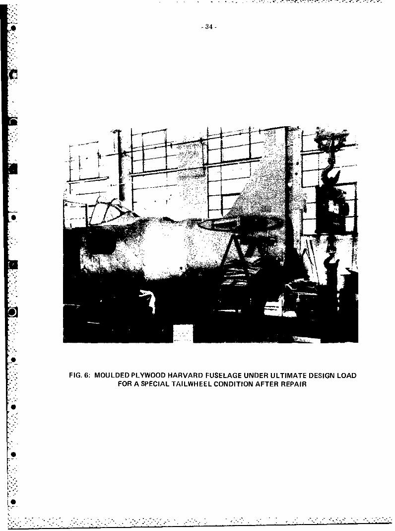
0 34-
::.:A.
b" --
"FIG. 6: MOULDED PLYWOOD HARVARD FUSELAGE UNDER ULTIMATE DESIGN LOADFOR A SPECIAL TAILWHEEL CONDITION AFTER REPAIR
0o
0:
0
V

-35-
F.|TL
"I
2,/
I•
- FI.7 OIOTLYMUTDTS FMUDDPYODHRADFSLG
.Ii" • ... ,.•..
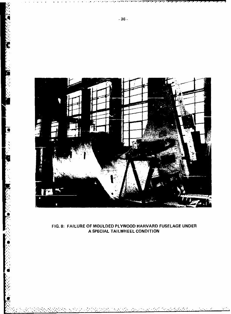
4 -36-
FIG. 8: FAILURE OF MOULDED PLYWOOD HARVARD FUSELAGE UNDERA SPECIAL TAILWH EEL CONDITION
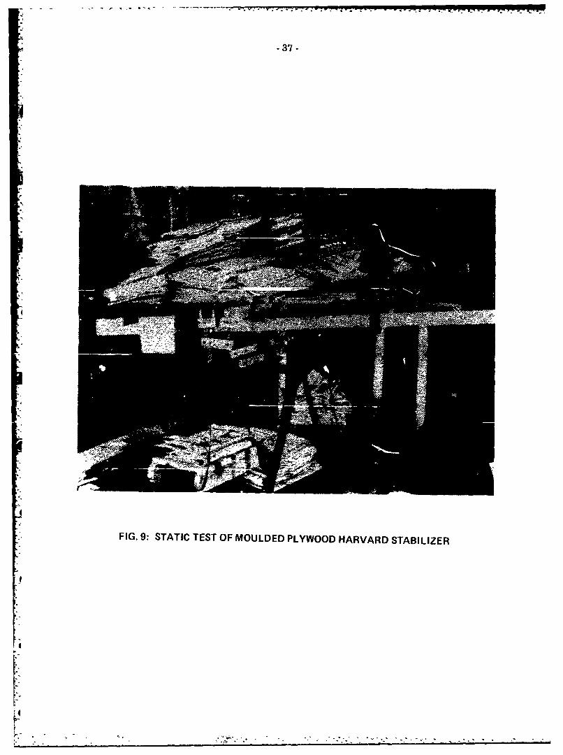
-37 -
FIG. 9: STATIC TEST OF MOULDED PLYWOOD HARVARD STABILIZER

- 38 -
FIG. 10: STATIC TEST OF MOULDED PLYWOOD HARVARD ELEVf\TOR

-39-
FIG. 111. TEST OF ANSON I MAINPLANE SHOWING SLATS USED TO DISTRIBUTESHOT BAG WEIGHTS

- 40-
I
'•V.Ilill
FIG. 12: ANSON MAINPLANE UNDER LOAD SHOWING WHIFFLETREEFOR APPLYING ENGINE AND UNDERCARRIAGE LOADS
:1
K-

.... . .~ .' w T v Ku VWlT '- . ' - NT t-f'M NMý Fr
-41-
FIG. 13: TEST SET-UP FOR ANSON TAILPLANE

-42-
FIG. 14: DROP TEST OF A CORNELL AIRCRAFT
4

443
FIG, 15: TEST SET-UP FOR CORNELL WING
4

T .Y. 77 4-ww,1 :
A -44-
F--
F~r-. __

-- - - - - - - - - - - - - -J ~- -¶ -W ' -. -. - - -- -. %
-45-
4I
FIG. 17, FAILURE OF A USED MOSQUITO WING AT 95% ULTIMATE FACTORED LOAD
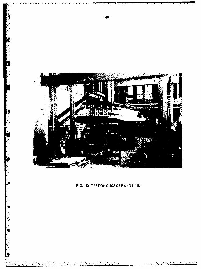
- - ... r- ý7 - - - - - -
-46-
FIG. 18: TEST OF C-102 DERWENT FIN
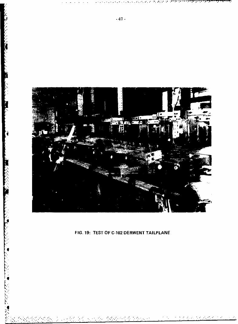
4 -47-
4
FIG. 19: TEST OF C-102 DERWENT TAILPLANE
IUI
Ik°

6 48--
FIG 20'ETSTU4O -12DRETMIFA N ETEFSLG

¾. -49.
-'"' -
FIG. 21: NRL 200 CHANNEL STRAIN RECORDER
. 5 5 * , - S S-

* -50-
FIG. 22: TEST OF C-100 TAILPLANE
41

FIG. 23:, TEST SET-UP FOR C-100 OUTER WING SHOWING RIVETED ATTACHMENTSTO LEADING EDGE

4 -52-
F1'G. 24:* C-100 EMPE NNAGE UNDER PROOF LOAD
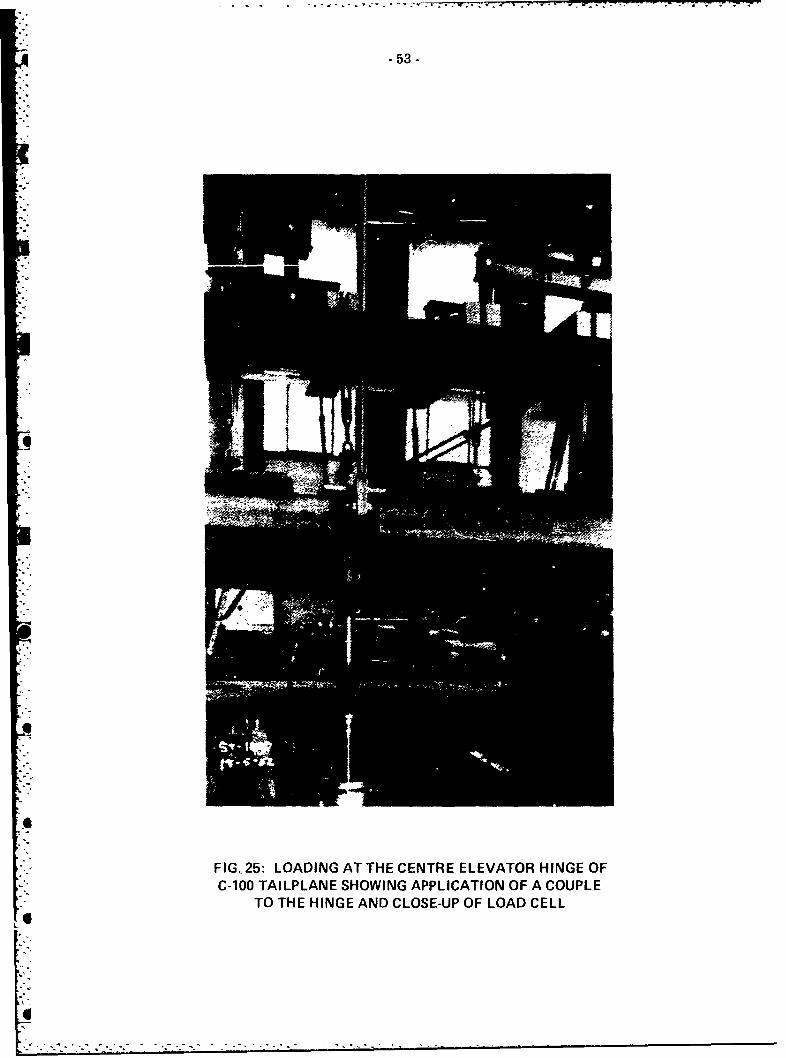
- 53 -
FIG. 25: LOADING AT THE CENTRE ELEVATOR HINGE OFC-100 TAILPLANE SHOWING APPLICATION OF A COUPLE
TO THE HINGE AND CLOSE-UP OF LOAD CELL
I-

i, -54-
'a.
6
FIG. 26- AUTOMATED REPEATED LIMIT LOAD TEST ON C-100 MARK 3 OUTER WING
I
I
IP

- 55 -
ww
0.C
Ix-10 -
z wn. 0 U)
>0) 44ClCl)
0. CO
w0 0U
Iw 0
w~ 0 Z
m >-
www
wwm>

* 56-
W I W2
SWITCH No I SWITCH No 2
MAXIMUM MINIMUM
LOAD PISTON LOAD PISTON
(small dia) ' 7(large dia)
TO
SOLE NOIO- OPERATED
VALVES
FIG. 28: PHOTOGRAPH AND SCHEMATIC OF REPEATED LOAD BALANCING SYSTEM

wE -57-
FIG. 29: STATIC TEST SET-UP FOR FOUND BROTHERS FBA-2 AIRFRAME
6
!I,!I.,
i-°

- 58 -
z3c
wil-
2w w
w 71 0ww
w >-
LaJ
-j-
AL uw
co
ww
28
zz2w
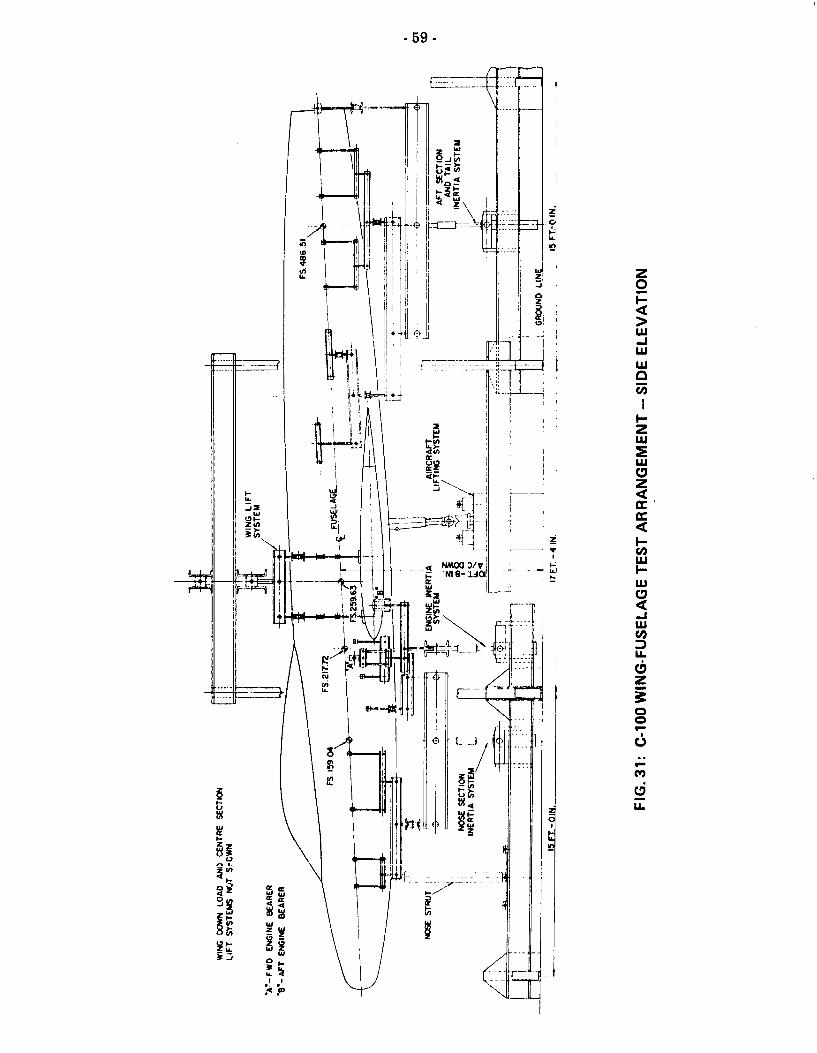
- 59 -
0-J
I wI
LI-
p-J
ujw
LaL
W Za:
31

-7-
FIG. 32: C-100 WING-FUSELAGE FATIGUE TEST ARRANGEMENT

Aq -61-
PORT AMPLITUDE PROGRAMME(SECONDARY)
0
=3:
0THIS LOADING SEQUENCECONSTITUTES ONE CYCLELOAD ON TAILPLANE ISPROPORTIONAL TO PRODUCTOF PRIMARY AND SECONDARYAMPLITUDE PROGRAMMES
SYMMETRIC ASYMMETRIC SYMMETRIC ASYMMETRICUP PORT DOWN DOWN STBD. DOWN
0
a STARBOARD AMPLITUDEPROGRAMME(SECONDARY)
6 "
"TOTAL BLOCK T!ME 2 70 HOURS5 -EQUIVALENT TO 50 FLIGHT HOURS
FREQUENCY CONSTANT AT 00494 CPS
03J
PRIMARY AMPLITUDE PROGRAMME
0L 50 100 150 20'0 250 300 350 400 450CYCLES PER BLOCK
FIG. 33: TEST LOAD HISTORY FOR C-100 TAILPLANE
e

4 -62-
U)U
L -j
IC zU
''4i
- Jfl iiV43LSAS HV3HC
LiL
I~i3J.SA

-63-
r')r
.71, --- 7
z uzccJ
0i
zo
0U
co
< co
_____ w__(L
97
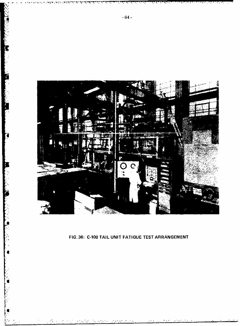
-64-
FIG. 36: C-100 TAIL UNIT FATIGUE TEST ARRANGEMENT

* -65-
wZ.. 0-
0- LiJ
0- 0 I- 0 -
00)
U))
0ow>> 0l: 0
0 40 ýj < oo-WU
z z Uz0 0 wmw L
w. wia. c0 oWI-X.n >
w
I.--
w 0
CL .,
w 0 0
Wr 0
-J CL0
aW 4-4
00
Nr c 0
z 4N
w N m L00 7 00()W
M 'n
1w I-
00wl w Z
4_- 40 0 -
(rO

*Q -66-
F
:" FIG. 38: VIEW OF TUTOR FATIGUE TEST SHOWING WING LOADING SYSTEM
a
f6T
|-a

-67.-
FGE.
•- FIG. 39: FUSELAGE LOADING SYSTEM FOR TUTOR WING FATIGUE TEST
_4
4
I

- .---- 9 -'--•*-. - r '.. r',•• rF,,W, -' r . ,q • •
9• -68-
FIG. 40: TUTOR WING FATIGUE TEST SET-UP
Vb
V*
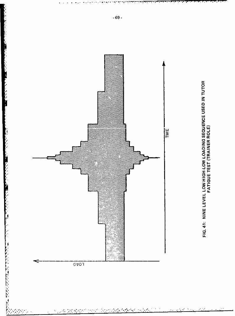
- - - -- -. -7-'.- -, -- - - - '~ -'~
-69-
0
zaLU
z:)LU-
0-WO
Z w
-J L
(DLU
-J U
NNw
zj
4 zNL-
aVo

_70-
•- FIG. 42; TRACKER WING FATIGUE TEST SET-UP
LT

a. 0
LL 00J
TOW SA
LLLLend
cvd
w
w
0 U.
0rL
0L
CIJ cco 0
g0O:C, Nc
- **.

* -72-
IT-
IT co
z
5
;CCa
OD-
II

-73-
SO
302
FIG. 4~ NACLLE LADItGSYSTE
-a- - < ~ .1 4
U..........

9 -74-
7 Loodcell N 3r
P21~
FIG. ~ ~ ~ ~ ~~ W 46 OUE0IGLAIGSSE
6o'
LodelM RActuator. X (Mx e

REPORT DOCUMENTATION PAGE / PAGE DE DOCUMENTATION DE RAPPORT
REPORT/RAPPORT REPORT/RAPPORT
NAE-AN-24 NRC No., 24089
la lb
REPORT SECURITY CLASSIFICATION DISTRIBUTION (LIMITATIONS)
CLASSIFICATION DE SECURITE DE RAPPORT
Unclassified Unlimited2 3
TITLE/SUBTITLE/TITRE/SOUS-TITRE
A History of Full-Scale Testing of Aircraft Structures atthe National Aeronautical Establishment
4
AUTHOR (S)/AUTEUR (S)
R.L. Hewitt5
SERIES/SERfE
Aeronautical Note
6
CORPORATE AUTHOR/PERFORMING AGENCV/AUTEUR D'ENTREPRISE/AGENCE D'EXECUTION
National Research Council CanadaNational Aeronautical Establishment Structures and Materials Laboratory
SPONSORING AGENCY/AGENCE DE SUBVENTION
8
DATE FILE/DOSSIER LAB ORDER PAGES FIGS/DIAGRAMMES
COMMANDE DU LAB,
85-01l, 81 469 10 11 12a 12b
NOTES
13
DESCRIPTORS (KEY WORDS)/MOTS-CLES
1. 'Aircraft - Structural Testing2. National Aeronautical Establishment
14
SUMMARY/SOMMAIRE
"This report presents an historical review of the work of theStructures and Materials Laboratory of NAE in the area of full scale testing"of large aircraft structures. It covers the period from 1941 to 1984, startingwith a static strength test of a moulded wood Anson fuselage and finishingwith a fatigue test of a Grumman Tracker wing. Brief details of the loadingarrangements and test results are included for each test component and"these are used to trace the development of the laboratory from the use ofrulers and shot bags to computer-controlled servo-hydraulic actuators.
15