Bernas ion source discharge simulation - a passion for ... · PDF fileBROQ EM NATIO,,*;PiL...
18
BROQ EM NATIO,,*;PiL LABORATORY BNL-7 9414-2OO7-CP Bernas ion source discharge simulation I. Rudskoy', T.V. Kulevoy', S.V. Petrenko', R.P. Kuibeda', D.N. Selemev', V.I. Pershin', A. Hershcovitch2, B.M. Johnson2, V.I. Gushenets3, E.M. Oks3, H.J. Poole4 'Institute for Theoretical and Experimental Physics, Moscow, 1 I721 8, Russia 3High Current Electronics Institute Russian Academy of Sciences, Tomsk, 634055 Russia 4PVL Oxnard, CA 93031-5023, USA 2BrookhavenNational Laboratory, Upton, NY 11973, USA Presented at the 12th International Conference on Ion Sources (ICIS 2007) Jeju, Korea August 26 - 31,2007 Collider-Accelerator Department Brookhaven National Laboratory P.O. Box 5000 Upton, NY 1 1973-5000 www.bnl.gov Notice: This manuscript has been authored by employees of Brookhaven Science Associates, LLC under Contract No. DE-AC02-98CH10886 with the US. Department of Energy. The publisher by accepting the manuscript for publication acknowledgesthat the United States Government retains a non-exclusive, paid-up, irrevocable, world-wide license to publish or reproduce the published form of this manuscript, or allow others to do so, for United States Government purposes. This preprint is intended for publication in a journal or proceedings. Since changes may be made before publication, it may not be cited or reproduced without the author's permission.
Transcript of Bernas ion source discharge simulation - a passion for ... · PDF fileBROQ EM NATIO,,*;PiL...

BROQ EM NATIO,,*;PiL LABORATORY
BNL-7 9414-2OO7-CP
Bernas ion source discharge simulation I. Rudskoy', T.V. Kulevoy', S.V. Petrenko', R.P. Kuibeda',
D.N. Selemev', V.I. Pershin', A. Hershcovitch2, B.M. Johnson2, V.I. Gushenets3, E.M. Oks3, H.J. Poole4
'Institute for Theoretical and Experimental Physics, Moscow, 1 I721 8, Russia
3High Current Electronics Institute Russian Academy of Sciences, Tomsk, 634055 Russia 4PVL Oxnard, CA 93031-5023, USA
2Brookhaven National Laboratory, Upton, NY 11973, USA
Presented at the 12th International Conference on Ion Sources (ICIS 2007) Jeju, Korea
August 26 - 31,2007
Collider-Accelerator Department Brookhaven National Laboratory
P.O. Box 5000 Upton, NY 1 1973-5000
www.bnl.gov
Notice: This manuscript has been authored by employees of Brookhaven Science Associates, LLC under Contract No. DE-AC02-98CH10886 with the US. Department of Energy. The publisher by accepting the manuscript for publication acknowledges that the United States Government retains a non-exclusive, paid-up, irrevocable, world-wide license to publish or reproduce the published form of this manuscript, or allow others to do so, for United States Government purposes.
This preprint is intended for publication in a journal or proceedings. Since changes may be made before publication, it may not be cited or reproduced without the author's permission.

DISCLAIMER
This report was prepared as an account of work sponsored by an agency of the United States Government. Neither the United States Government nor any agency thereof, nor any of their employees, nor any of their contractors, subcontractors, or their employees, makes any warranty, express or implied, or assumes any legal liability or responsibility for the accuracy, completeness, or any third party's use or the results of such use of any information, apparatus, product, or process disclosed, or represents that its use would not infringe privately owned rights. Reference herein to any specific commercial product, process, or service by trade name, trademark, manufacturer, or otherwise, does not necessarily constitute or imply its endorsement, recommendation, or favoring by the United States Government or any agency thereof or its contractors or subcontractors. The views and opinions of authors expressed herein do not necessarily state or reflect those of the United States Government or any agency thereof
Bernas Ion Source Discharge Simulation*")
I. Rudskoy', T.V. Kulevov', S.V. Petrenko', R.P. Kuibeda', D.N. Seleznev', V.I. Pershin', A. Hershcovitch2, B.M. Johnson2, V.I. Gushenets3, E.M. Oks3, H.P. Poole4.
I Institute for Theoretical and Experimental Physics, Moscow 11 7218, Russia Brookhaven National Laboratory, Upton, New York 11 973, USA
' High Current Electronics Institute Russian Academy of Sciences, Tomsk, 634055 Russia PVI, Oxnard, California 930314023. USA
Fax: +7-(495)-123-3028 E-mail address: kulevov@,itep.ru
2
Abstract. The joint research and development program is continued to develop steady-state ion
source of decaborane beam for ion implantation industry. Bemas ion source is the wide used ion source for ion implantation industry. The new simulation code was developed for the Bemas ion
source discharge simulation. We present first results of the simulation for several materials
interested in semiconductors. As well the comparison of results obtained with experimental data
obtained at the ITEP ion source test-bench is presented.
Introduction
The joint research and development program is continued to develop steady-state ion
source for ion implantation industry. Bemas ion source is the wide used ion source for ion
implantation industry. Therefore, in framework of investigation of low energy beam generation for ion implantation, we use ITEP version of Bemas ion source [ 11 - [ 31. As the technology and
applications continue to grow, there is a need for development of plasma and ion sources with
clearly specified characteristic. Manufacturing sources of this kind at present could not be accomplished without comprehensive numerical studies at the project stage. It is even more
important when the ion source for low energy implantation is developed. Universal plasma
models based on Vlasov-Boltzmann equation can be used to describe a wide variety of these
* This work was supported by the DOE IPP Trust 2 program. (CRDF GAP Grant # RPO 10225 - BNL)
a) Contributed paper, published as part of the Proceedings of the 12th International Conference on Ion
Sources, Jeju, Korea, August 2007
. sources. Recently the most commonly encountered numerical approach to solve this equation is
the Monte-Carlo Particle-In-Cell (MCPIC) method also known as Particle-In-Cell method with
Monte-Carlo collisions. In this paper we present the 2D3V numerical code PICSIS-2D realizing
MCPIC method and the results of simulations as applied to Bernas ion sources. The numerical results are compared with experimental data.
Simulation model
Plasma filling an ion source is supposed to consist of electrons and different kinds of ions
of all charge states, which are represented by distribution functions f k (x’,G,t) , where x’ is the
particle position and v’ is the particle velocity. As usual the distribution functions f k give the
probability of finding particles of sort k in a given volume of phase space. The electrons and ions
in the plasma under consideration are assumed to interact via electricEfields, static
magnetic fields and binary collisions. The neutral gas is treated as a uniform background of
atoms or molecules with a constant temperature. An appropriate equation set can be written as follows:
dfk --+v-+---I, af, -af, ‘k af, - dt d t dx’ mk C5
Here mk is the particle mass. The right-hand member I , in this equation is the collision
integral which defines changes of distribution functions f k under collisions. The following
electron collisions are included into consideration: elastic electron-electron, electron-ion and electron-neutral collisions; and inelastic ionizing and exciting collisions with neutrals and ions.
Ion collisions included are elastic ion-neutral collisions and charge exchange collisions.
The force Fk on the particles with the charge qk is the Lorentz force given by:
Fk = q , ( E + v ’ x B )
The electric field 2 appeared in the equation is defined by plasma self-field and external ~ electrodes. It is obtained from solution of the Poisson equation:
i j .E = 4zp
The static external magnetic field $ should be calculated as a preliminary in analytical or numerical ways. It can be set also as an experimental data table. The time varying magnetic field
induced by currents of charged particles is neglected here since for the problem involved it is
much smaller than other forces acting on the particles.

The Monte-Carlo Particle-In-Cell numerical approach chosen for solving the equations
makes use of finite elements or quasi-particles to represent the distribution functionsf,, Each
finite particle stands for the group of physical particles and has a mass and charge accordingly to
the type of ions or electrons. Trajectories of these particles in phase space represent the evolution
of the respective distribution functions and'can be found by time integrating of the motion
equations:
These two equations are solved using explicit time-centered leapfrog [ 41, [ 51. A spatial
grid (or mesh) overlaying all of the particles is used in order to calculate charge densities p at the
grid points from the particle positions (so-called charge weighting to grid). These densities are
then used to solve the Poisson equation on the grid. Then the particles forces are interpolated
from the grid (so-called field weighting to particles). The code provides various interpolated
functions for charge and force: zero-, first- and second-order splines depending on the problem
under consideration. The solution of Poisson equation is found by the double fast Fourier
transformation [ 61 in a 2D frame of reference (plane or cylindrical). The Dirichlet boundary
conditions are used at conductive surfaces with known potentials and the Neumann conditions -
at the axis (in case of cylindrical geometry). These tree procedures: charge weighting, field
calculation and force weighting are performed at an every integration step to provide a self-
consistent solution of these equations.
The collisions events are modeled using a Monte-Carlo technique, where random
numbers are used to choose a time between collisions, to pick a particular event and to define
post collision velocities. Depending on collision frequencies we use an approach proposed [ 41 (if a cumulative probability at an integration step >0.01), or a simplified scheme [ 71 - in the
opposite case. To shorten consumption time an ad hoc table of collision frequencies is generated
in the beginning of simulation.
Elastic collisions with neutrals are regarded in hard sphere approximation. For inelastic
collisions the respective analytical or experimental differential cross-sections are applied.
Binary collisions of charged particles are regarded in the way described by [ 81, [ 91. To define
an interaction range for colliding particles we use the same mesh as on solution of the Poisson
equation. Small-angle scattering probabilities are supposed to follow the well-known Spitzer
equation [ lo].
Numerical results
At first, the model described above was tested on the problems having analytical
solutions: the development of two-beam instability, the ion charge state relaxation, the drift in
crossed electric and magnetic fields, the momentum isotopization and establishing of thermal
equilibrium in plasmas. After that, it has been applied to the simulation of DC glow discharge.
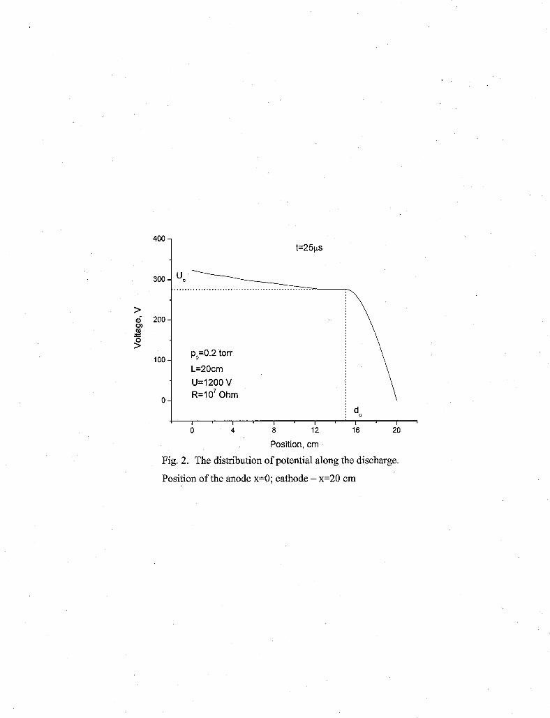
We have simulated the development of DC glow discharge in a tube of 20cm long and 1 cm in
diameter filled with hydrogen under the pressure of 0.2 torr. It was assumed that the voltage of
1200V was applied through the resistor of lo7 Ohm to the platinum electrodes. Elastic
scattering, ionization and excitation of vibration, rotation and main electronic levels were taken
into account as well as secondary electron emission from the cathode under ion impacts. All particles reaching the walls or electrodes are considered as killed.
To initiate the discharge we have supposed that the cathode can emit electrons with the temperature of filament (-0.1 eV). About 1 O6 finite particles were under consideration.
The results obtained are depicted in Fig. 1 - Fig. 3. In 5 ps after the beginning the
discharge became stabilize and steady state discharge current remain approximately the same
during all computational time (up to 50 ps). Since the total light emission usually follows the
electron density one can see the most intensive negative glow and a stratified positive column.
The values of cathode drop U, (- 280 V) and the thickness of cathode layer d, (- 5.lcm) good
agree with tabulated experimental data - 276 V and 5 cm respectively. Moreover in the Fig. 3
one can see that the strata are not stable and run towards the cathode in accordance with
experimental observations. The more fine structure of the discharge (Aston and cathode dark
spaces) can be also distinguished by analyzing of electron energy distribution.
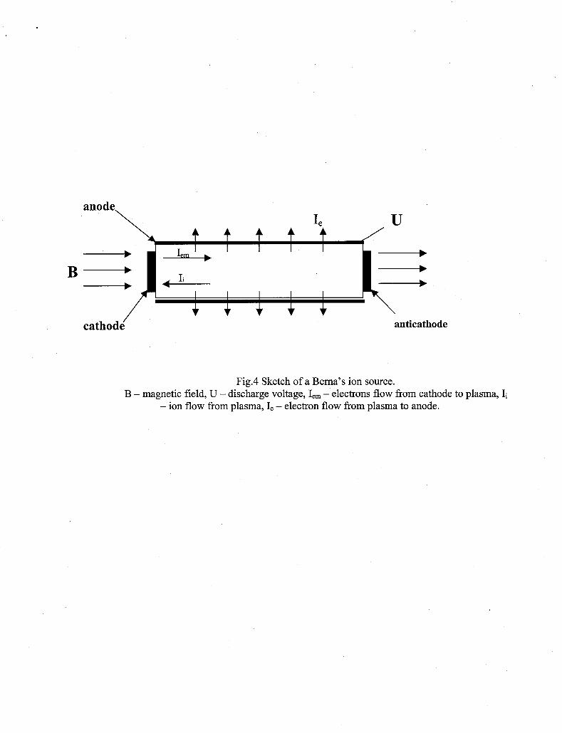
Finally, the code has been applied for simulation of Bemas ion sources. Schematic sketch
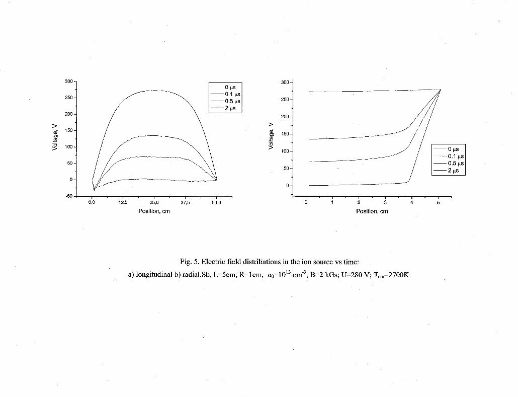
of an ion source is shown in Fig. 4. It was found that there are different modes of ion source
operating. One of them does not lead to arising of self-sustaining discharge (see Fig. 5 and Fig.
6) due to significant suppression of electron emission by the negative space charge. Another one
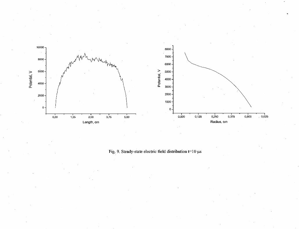
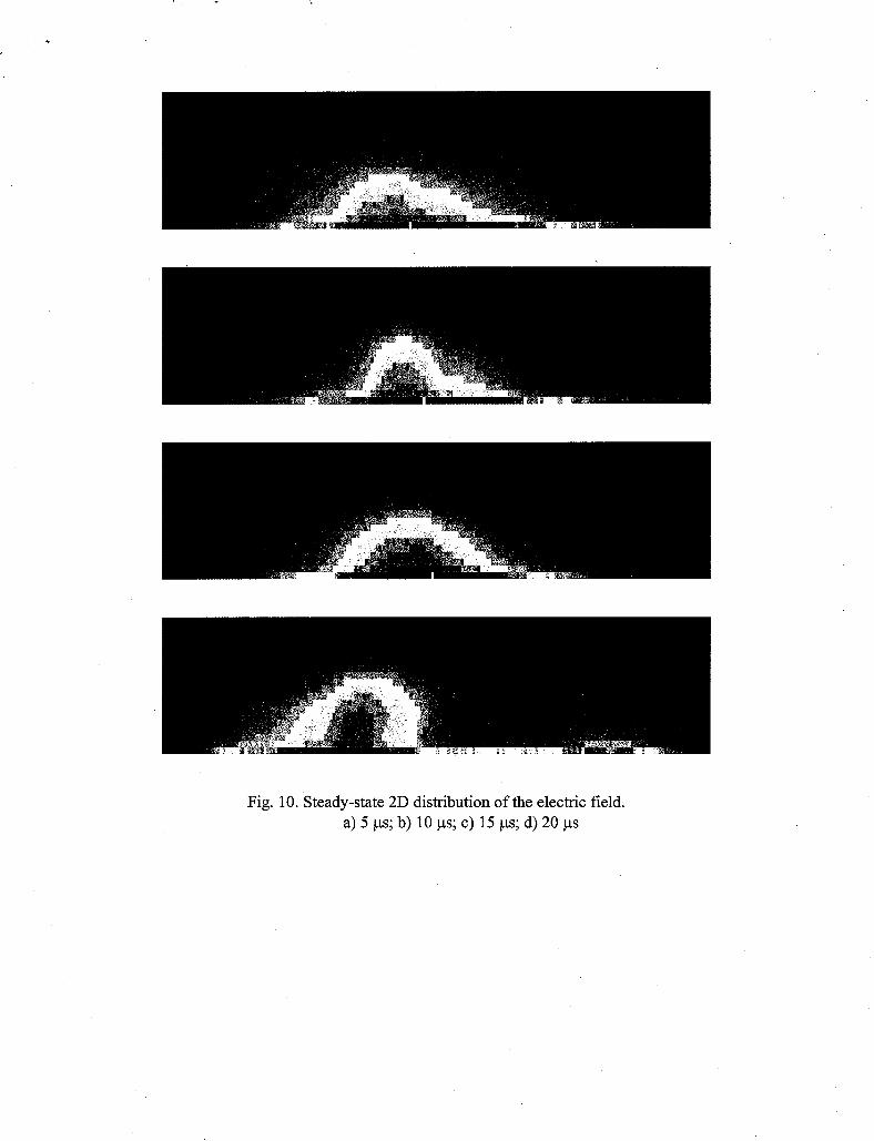
initiates a discharge shown in Fig. 7 - Fig. 10. In this case we have used for simulation the real
parameters of the ion source operating in ITEP, Moscow [ 11. Both the steady-state value of
current discharge (Id=260mA) and the current of the extracted ions (Il=lOmA for Sb+' ) are in a
good agreement with experimental data [ 31.
Conclusion
The results obtained clearly confirm that the numerical code depicted in this paper
represents an adequate model of physical processes in the wide range of ion source plasmas. It
can be successfully used for ion source development for low energy implantation. As well it can

be used in the course for development of various kinds discharge ion sources. For example, we
hope that after some modifications and improvements undertaking at present time it will work
for ECR ion sources modeling.
Acknowledgements
This work was supported by the DOE IPP Trust 2 program. (CRDF GAP Grant # RPO
10225 - BNL).
References
[ 11 A. Hershcovitch, V. A. Batalin, A. S. Bugaev, V. I. Gushenets, B. M. Johnson, A. A. Kolomiets, G. N. Kropachev, R. P. Kuibeda, T. V. Kulevoy, I. V. Litovko, E. S. Masunov, E. M. Oks, V. I. Pershin, S. V. Petrenko, S. M. Polozov, H. J. Poole, I. Rudskoy, D. N. Seleznetr,
P. A. Storozhenko, A. Ya. Svarovski, G. Yu. Yushkov, Ion sources for the varying needs of ion
implantation, Rev. Sci. Instrum. 77,03B510 (2006)
[ 21 T. V. Kulevoy, S. V. Petrenko, R. P. Kuibeda, V. A. Batalin, V. I. Pershin, A. V. Koslov,
Yu. B. Stasevich, A. Hershcovitch, H. J. Poole, E. M. Oks, V. I. Gushenets, H. J. Poole,
P. A. Storozhenko, E. L. Gurkova, 0. V. Alexeenko, Decaborane beam from ITEP Bema ion
source - RSI, Rev. Sci. Instrum. 77(3) 03C102 (2006)
[ 31 T. V. Kulevoy, R. P. Kuibeda, S. V. Petrenko, V. A. Batalin, V. I. Pershin, G. N. Kropachev,
A. Hershcovitch, B. M. Johnson, V. I. Gushenets, E. M. Oks, H. J. Poole, ITEP Berna IS with additional e-beam - RSI, Rev. Sci. Instrum. 77(3) 03C110 (2006)
[ 41 R.W. Hockney and J.W. Eastwood, Computer Simulation Using Particles, New York: McGraw-Hill, 198 1
[ 51 J. P. Boris, K.V. Roberts, J. Comput. Phys, v. 4, pp. 552-571, 1969
[ 61 M.H.Hughes, Comput. Phys. Commun., v.2, pp.157-167, 1971
[ 71 C.K.Birdsal1, IEEE Trans. Plasma Sci., v. 19, pp. 65-85, 1991
[ 81 T. Takizuka and H. Abe, J. Comput. Phys, v. 25, p. 205-219, 1977
[ 91 J.M. Dawson, S. Ma, R.D. Sydora, Comput. Phys. Commun., v. 77, pp. 190-195, 1993
[ 101 L.Spitzer, Physics of Fully Ionised Gases, New York, Wiley-Interscience, 1962.

Figures.
Fig. 1 Electron density distribution along the discharge. Position of the anode x=O; cathode -
x=20 cm
Fig. 2 The distribution of potential along the discharge. Position of the anode x=O; cathode - x=20 cm.
Fig. 3 Time evolution of electron density
Fig. 4 Pictorial description of the Bema’s ion source. Blue - cathode and anticathode, Black -
anode, U - discharge voltage, B - magnetic field, I, - electrons’ flow cathode to plasma, I, - electrons’ flow from plasma to anode, I; - ions flow from plasma to electrodes.
Fig. 5 Electric field distributions in the ion source vs time: a) longitudinal b) radial.
Sb, L=5cm; R=lcm; no=1013 cm”; B=2 kGs; U=280 V; T,=2700K.
Fig. 6. 2D distribution of the electric field vs time. a) initial distribution; b) 0 . 1 ~ ~ ; c) 0.5 ps; d)
2 P
Fig. 7 Electric field distributions in the ion source vs time: a) longitudinal b) radial. Sb, L=5cm;
R=0.5 cm; no=1013 cm”; B=600Gs; U=280 V; Tem=2700K.
Fig. 8.2D distribution of the electric field vs time. a) initial distribution; b) lps; c) 3 ps; d) 5 ps
Fig. 9. Steady-state electric field distribution t-10 ps
Fig. 10 Steady-state 2D distribution of the electric field. a) 5 ps; b) 10 ps; c) 15 ps; d) 20 ps

+ m p,=0.2 torr d fn L=2Ocm U u=1200 v f 60
c 2 c o 40- Q)
w -
20 -
0 -
R=107 Ohm
L ' A ' i . A 12 16 20
Position, cm
Fig. 1. Electron density distribution along the discharge.
Position of the anode x=O; cathode - x=20 cm
u=1200 v R=l O7 Ohm
I I I I 0 4 a 12
Position, cm
d C - 16 20
Fig. 2. The distribution of potential along the discharge.
Position of the anode x=O; cathode - x=20 cm

140 -
120 -
100 -
80 -
60 -
40 -
20 - 0-
p0=0.2 torr
L=20 cm
u=1200 v R=107 Ohm
- lops - 10.2ps ~ 1 0 . 4 ~ ~ - 1 0 . 6 ~ ~
-20 ! I 1 I I I I I
0 4 8 12 16 20
Position, cm
Fig. 3 Time evolution of electron density
anode U
t t t t 1, ' ' -
B- I, I I I I I
f f f f f anticathode
Fig.4 Sketch of a Bema's ion source. B - magnetic field, U - discharge voltage, I, - electrons flow from cathode to plasma, Ii
- ion flow from plasma, I, - electron flow from plasma to anode.
n
(d
Y

Fig. 6. 2D distribution of the electric field vs time.
a) initial distribution; b) 0 .1~s ; c) 0.5 ps; d) 2 ps


Fig. 8 2D distribution of the electric field vs time.
a) initial distribution; b) lp; c) 3 ps; d) 5 ps
m 2 0-
i'
l'
l~
l'
l'
l~
z 0
0
0
0 0
0 0 0
W
0 0 0
03 s
Ri 0
0
0
?
Fig. 10. Steady-state 2D distribution of the electric field. a) 5 ps; b) 10 ps; c) 15 ps; d) 20 ps