BER DEGRADATION OF MC-CDMA AT HIGH SNR...
50
BER DEGRADATION OF MC-CDMA AT HIGH SNR WITH MMSE EQUALIZATION AND RESIDUAL FREQUENCY OFFSET A thesis submitted in partial fulfilment of the requirements for the degree of Master of Science (by research) in Communication Systems and Signal Processing by Harinath Reddy P 200431004 [email protected] Communications Research Center INTERNATIONAL INSTITUTE OF INFORMATION TECHNOLOGY GACHIBOWLI, HYDERABAD, A.P., INDIA - 500 032 May 2010
-
Upload
truongduong -
Category
Documents
-
view
215 -
download
0
Transcript of BER DEGRADATION OF MC-CDMA AT HIGH SNR...

BER DEGRADATION OF MC-CDMA AT HIGH SNR WITH
MMSE EQUALIZATION AND RESIDUAL FREQUENCY OFFSET
A thesis submitted in partial fulfilment of
the requirements for the degree of
Master of Science (by research)
in
Communication Systems and Signal Processing
by
Harinath Reddy P
200431004
Communications Research Center
INTERNATIONAL INSTITUTE OF INFORMATION TECHNOLOGY
GACHIBOWLI, HYDERABAD, A.P., INDIA - 500 032
May 2010
INTERNATIONAL INSTITUTE OF INFORMATION TECHNOLOGY
GACHIBOWLI, HYDERABAD, A.P., INDIA - 500 032
CERTIFICATE
It is certified that the work contained in this thesis, titled “BER Degradation of MC-
CDMA at High SNR with MMSE Equalization and Residual Frequency Offset ” by Har-
inath Reddy P, has been carried out under my supervision and it is fully adequate in
scope and quality as a dissertation for the degree of Master of Science.
Date Prof V U Reddy (Advisor)
c© Copyright by Harinath Reddy P 2010
All Rights Reserved
ii
Abstract
Multicarrier Code Division Multiple Access (MC-CDMA) is an attractive technique
for high speed wireless data transmission in view of its advantages over orthogonal
frequency division multiplexing. In this thesis, we analyze the performance of fully
loaded downlink MC-CDMA systems with minimum mean square error (MMSE)
equalizer in the presence of residual frequency offset (RFO) in multipath Rayleigh
fading channels. We first show that as the SNR is increased beyond a value, referred
as threshold SNR, the performance degrades. We then analyze the cause for this
behavior and propose a remedy to prevent the degradation by regularizing the co-
efficient(s) of the equalizer, and use the regularized equalizer for SNRs beyond the
threshold value.
The threshold SNR depends on the RFO and the profile of multipath channel.
We suggest two methods for estimating this SNR, one gives close to the true value
but requires the knowledge of RFO and the channel state information (CSI), while
the other gives an approximate value but requires only CSI. We first show that if the
actual value of RFO is less than the assumed, the threshold SNR estimate based on
the assumed RFO will still be appropriate. Next, we show that the regularization
based on the approximate value also prevents the degradation, but the performance at
higher SNRs is slightly poorer compared to that with the better estimate. Numerical
and simulation results are provided to support the analysis.
iv
Acknowledgement
First and foremost, I would like to express my gratitude to my advisor, Prof V U
Reddy, for his valuable support, guidance, and patience in my graduate education. It
has been a great learning experience and this work could not have been accomplished
without his constant encouragement and patience.
I would like to thank all the faculty and staff members for their support, interac-
tion and advice during my stay at IIIT-H.
I am thankful to my labmates and friends in CRC, and all the past and present
students of IIIT who made my stay memorable.
v

Contents
Abstract iv
Acknowledgement v
1 Introduction 1
1.1 Multi-Carrier Transmission . . . . . . . . . . . . . . . . . . . . . . . . 1
1.1.1 OFDM Systems . . . . . . . . . . . . . . . . . . . . . . . . . . 2
1.1.2 MC-CDMA Systems . . . . . . . . . . . . . . . . . . . . . . . 4
1.2 Effects of RFO . . . . . . . . . . . . . . . . . . . . . . . . . . . . . . 6
1.3 Contributions . . . . . . . . . . . . . . . . . . . . . . . . . . . . . . . 8
1.4 Thesis Organization . . . . . . . . . . . . . . . . . . . . . . . . . . . . 9
2 BER Performance of MC-CDMA 10
2.1 MMSE and ZF Equalizers . . . . . . . . . . . . . . . . . . . . . . . . 12
2.2 BER Performance of MC-CDMA with ZF and MMSE equalizers . . . 13
2.3 Degradation of MMSE Equalizer Performance at High SNRs . . . . . 15
3 Cause and Remedy for the Degradation 20
3.1 Cause . . . . . . . . . . . . . . . . . . . . . . . . . . . . . . . . . . . 20
3.2 Remedy . . . . . . . . . . . . . . . . . . . . . . . . . . . . . . . . . . 22
3.3 Estimating the Threshold SNR . . . . . . . . . . . . . . . . . . . . . 23
3.4 An Approximate Value of Threshold SNR . . . . . . . . . . . . . . . 24
4 Simulation Results 28
vi
5 Conclusions 33
5.1 Future Work . . . . . . . . . . . . . . . . . . . . . . . . . . . . . . . . 33
A Derivation of MMSE Equalizer for MC-CDMA 34
Bibliography 37
vii

List of Tables
2.1 Channel model given in [18] . . . . . . . . . . . . . . . . . . . . . . . 17
2.2 Channel realizations used in the performance plots of Figs. 2.1 to 3.3
(CR=channel realization) . . . . . . . . . . . . . . . . . . . . . . . . 17
viii
List of Figures
1.1 Transmitter of an OFDM system . . . . . . . . . . . . . . . . . . . . 3
1.2 Receiver of an OFDM system . . . . . . . . . . . . . . . . . . . . . . 3
1.3 Transmitter of an MC-CDMA system . . . . . . . . . . . . . . . . . . 6
1.4 Receiver of an MC-CDMA system . . . . . . . . . . . . . . . . . . . . 7
2.1 BER Performance of MC-CDMA with MMSE and ZF equalizers, eval-
uated from (2.19), for RFO=0.05 (plots marked 1) and RFO=0.03
(plots marked 2) (Nf=64 and the channel realization is CR-1 given in
Table 2.2, and the symbols are from 4-QAM constellation with P = 1) 18
2.2 BER Performance of MC-CDMA with MMSE and ZF equalizers, eval-
uated from (2.19), for three different channel realizations (RFO=0.05,
Nf=64 and CR-1, CR-2, CR-3 refer to the channel realizations given
in Table 2.2, and symbols are from 4-QAM constellation with P = 1 ) 19
3.1 E(am3a3∗
m ) as a function of SNR for the channel realization CR-1 given
in Table 2.2 (Nf=64 and RFO=0.05, and symbols are from 4-QAM
constellation with P = 1) . . . . . . . . . . . . . . . . . . . . . . . . . 25
3.2 E(am,k3a3∗
m,k) as a function of SNR for the channel realization CR-1
given in Table 2.2 (Nf=64, RFO=0.05, plot marked 1-weakest bin,
plot marked 2-next weakest bin, plot marked 3-strongest bin. Symbols
are from 4-QAM constellation with P = 1) . . . . . . . . . . . . . . . 26
ix
3.3 BER Performance of MC-CDMA with MMSE equalizer, evaluated us-
ing (2.19) (Plots 1 and 2 are without regularization, plots 1’ and 2’ are
with regularization based on the threshold SNR estimated from plot 1
as described in Sec. 3.3, plots 1” and 2” are with regularization based
on the threshold SNR computed from (3.4). Plots (1, 1’, 1”) and (2,
2’, 2”) correspond to RFOs=0.05 and 0.03, respectively. Nf=64 and
channel realization is CR-1 given in Table 2.2, and symbols are from
4-QAM constellation with P = 1) . . . . . . . . . . . . . . . . . . . . 27
4.1 BER performance of MC-CDMA for Nf=64 with MMSE equalizer,
averaged over 106 realizations of the channel model given in [18] with
tap variances normalized such that the total variance is one (Plots 1,
2, 3 are without regularization, 1’, 2’, 3’ are with regularization based
on the threshold SNR estimated as given in Sec. 3.3 with RFO=0.05,
plots 1”, 2”, 3” are with regularization based on the threshold SNR
computed from (3.4). Plots (1,1’,1”), (2,2’,2”) and (3,3’,3”) correspond
to RFOs=0.05, 0.03 and 0.01, respectively. Symbols are from 4-QAM
constellation with P=1) . . . . . . . . . . . . . . . . . . . . . . . . . 30
4.2 BER performance of MC-CDMA for Nf=16 with MMSE equalizer,
averaged over 106 realizations of the channel model given in [18] with
tap variances normalized such that the total variance is one (Plots
1, 2 are without regularization, plots 1”, 2” are with regularization
based on the threshold SNR computed from (3.4). Plots (1,1”), (2,2”)
correspond to RFOs=0.05 and 0.03, respectively. Symbols are from
4-QAM constellation with P=1) . . . . . . . . . . . . . . . . . . . . . 31
x

4.3 BER performance of MC-CDMA for Nf=256 with MMSE equalizer,
averaged over 106 realizations of the channel model given in [18] with
tap variances normalized such that the total variance is one (Plots
1, 2 are without regularization, plots 1”, 2” are with regularization
corresponding to the 5 bins whose gains are least of the 256 bin gains,
computing the threshold SNR from (3.4) by replacing λmin with the
corresponding bin gain. Plots (1,1”), (2,2”) correspond to RFOs=0.05
and 0.03, respectively. Symbols are from 4-QAM constellation with
P=1) . . . . . . . . . . . . . . . . . . . . . . . . . . . . . . . . . . . . 32
xi
Chapter 1
Introduction
Third Generation (3G) mobile communication systems allow us to have whole new
ways to communicate and access information. They have already been deployed in
several countries. 3G is a recent technology, and a lot of research is going on in this
area. Further research efforts are especially focussed on systems that can provide
much higher data rates and seamless connectivity. Such systems are categorized un-
der Fourth Generation (4G). While wide-band systems are considered by many to
be a natural choice to provide higher data rates, the spectrum required comes at a
very high cost. Spectral efficiency is always a factor on the choice of any wireless
technology. Wide-band systems usually require complex receivers as the channel is
frequency selective due to the presence of large number of resolvable multipaths.
1.1 Multi-Carrier Transmission
The principle of multi-carrier transmission is to convert a high-rate data-stream into
several parallel low-rate data streams. In other words, a wide band channel is divided
into many parallel narrow band sub-channels. Since the symbol rate on each sub-
carrier associated with each sub-channel is much less than the initial symbol rate, the
effects of delay spread, i.e., ISI, significantly decrease, reducing the complexity of the
equalizer.
1

CHAPTER 1. INTRODUCTION 2
1.1.1 OFDM Systems
OFDM is a low-complex technique to efficiently modulate multiple sub-carriers by
using digital signal processing [1]. Several present and upcoming wireless communi-
cation standards adopted OFDM as the modulation format. The major reasons for
choosing OFDM are:
1. A frequency selective channel is transformed into sum of frequency flat sub-
channels.
2. It is very efficient in spectrum usage.
3. Modulator and demodulator are implemented very efficiently using IFFT and
FFT.
4. A single tap frequency-domain equalizer (same as zero-forcing equalizer) is ad-
equate at the receiver.
The OFDM transmitter and receiver block diagrams are shown in Fig. 1.1 and
1.2 respectively. At the transmitter, the data bits are first mapped to symbols and
then sent to the serial-to-parallel converter. The output of serial-to-parallel converter
is sent to IFFT block. In the IFFT block, the IFFT of the symbols is computed
and the output of this block is sent to Add Guard Interval block which adds cyclic
prefix (to prevent the inter-block interference[20] and make the linear convolution as
circular convolution which helps in reducing the complexity of the equalizer at the
receiver) and sends the resultant output to parallel-to-serial converter. The output
of the parallel-to-serial converter is transmitted.
The received signal is first passed through a serial to parallel converter and then
given to the FFT block after removing the guard interval (cyclic prefix). The output
of the FFT block is fed to the equalizer block and its output is given to parallel to

CHAPTER 1. INTRODUCTION 3
Figure 1.1: Transmitter of an OFDM system
Figure 1.2: Receiver of an OFDM system

CHAPTER 1. INTRODUCTION 4
serial converter. The output of parallel to serial converter is sent to symbol de-mapper.
A frequency selective channel may result in some bins being very weak. The sym-
bols loaded in these bins will experience a poor SNR at the receiver. Consequently,
symbol error probability in these bins will be high even at high SNRs. Consider a
mechanism whereby each symbol is carried by all the bins, and we use certain orthog-
onal spreading sequences such that decoding of each symbol is possible with minimal
interference from other symbols. Then, symbol carried by all the bins can be com-
bined to give a strengthened symbol if we have the perfect knowledge of the channel.
The loss of orthogonality among the spreading sequences, caused by the frequency se-
lective nature of the channel, introduces multi-code interference (MCI) [3] which can
be minimized by applying minimum mean square error (MMSE) equalization. This
method of spreading the symbols across the sub-carriers is called Multi Carrier Code
Division Multiple Access (MC-CDMA) [4] and the systems which use this method
are MC-CDMA systems.
1.1.2 MC-CDMA Systems
In MC-CDMA systems the symbols are spread across the sub-carriers. By spreading,
we get frequency diversity. Combination of frequency diversity and an appropriate
equalizer yields improved bit error rate (BER) performance in multipath channels
compared to OFDM [2].
As MC-CDMA is implemented by spreading across the sub-carriers, we use Walsh-
Hadamard codes for spreading. The Walsh-Hadamard matrix is given by
W2 =
[1 1
1 −1
](1.1)
W2n =
[W2n−1 W2n−1
W2n−1 −W2n−1
](1.2)

CHAPTER 1. INTRODUCTION 5
for n ≥ 2. We assume that the frequency spreading factor is same as the number of
sub-carriers, Nf , which is an integer power of 2. Let W denote the Walsh-Hadamard
matrix of size Nf ×Nf
W =[
w0 w1 . . . wNf−1
](1.3)
where wk = [w0,k w1,k . . . wNf−1,k]T with the superscript T denoting transpose of a
vector.
Let the symbols be ak, 0 ≤ k ≤ Nf − 1. The symbol ak is spreaded in frequency
by wk. The output of the frequency spreader block (see Fig. 1.3) is given by
x =
Nf−1∑k=0
wkak (1.4)
where x is a vector of size Nf × 1. From the above equation its clear that we are
considering a fully loaded downlink MC-CDMA system. The output of this block is
fed to the IFFT block whose output is given by
y = Fx (1.5)
where y = [y0 y1 · · · yNf−1]T and F denotes normalized IFFT matrix given by
F =1√Nf
1 1 . . . . . . 1
1 u u2 . . . uNf−1
1 u2 u4 . . . u2(Nf−1)
1... . . .
... . . .
1 uNf−1 . . . . . . u(Nf−1)(Nf−1)
NfxNf
(1.6)
where u = e( 2πi
Nf)and i =
√−1. The output y is sent to the Add Guard Interval block
where the cyclic prefix of length (L− 1) is added giving
y =[yNf−L+1 yNf−L . . . yNf−1 y0 . . . yNf−1
]T
(Nf+L−1)×1(1.7)
CHAPTER 1. INTRODUCTION 6
Figure 1.3: Transmitter of an MC-CDMA system
We add the cyclic prefix because it prevents the inter-block interference (provided the
number of channel taps is less than or equal to L)[20] and makes the linear convolution
as circular convolution which helps in reducing the complexity of the equalizer at the
receiver. y is transmitted after parallel to serial conversion.
The receiver block diagram is shown in Fig. 1.4. The received signal is first passed
through a serial to parallel converter and then given to the FFT block after removing
the guard interval (cyclic prefix). The output of the FFT block is fed to equalizer
block and its output is given to the frequency despreader block. The other blocks are
parallel to serial converter and symbol de-mapper (see Fig. 1.4).
1.2 Effects of RFO
In OFDM systems, timing and frequency synchronization is very important [5]. In
particular, lack of frequency synchronization causes loss of orthogonality among the

CHAPTER 1. INTRODUCTION 7
Figure 1.4: Receiver of an MC-CDMA system

CHAPTER 1. INTRODUCTION 8
sub-carriers thereby introducing the inter carrier interference (ICI). Though several
algorithms are proposed for estimating and correcting the frequency offset [6]-[10],
there will always be some amount of residual frequency offset (RFO) left uncompen-
sated. In [11], the authors analyze the BER performance of the OFDM in multipath
fading channels in the presence of RFO.
As MC-CDMA is a combination of OFDM and CDMA, it is sensitive to RFO
[12]-[15]. In [12] and [13], the authors analysed the performance of MC-CDMA in the
presence of RFO using equal gain combining and maximal ratio combining equalizers.
In [14], the authors compared the performance of maximal ratio combining (MRC)
and equal gain combining (EGC) with synchronization errors over fading channels.
In [15], the authors discussed the sensitivity of two-dimensional spreading schemes,
such as orthogonal frequency code division multiplexing, to synchronization errors
using zero-forcing (ZF) and minimum mean square error (MMSE) equalizers.
In this thesis we analysed the performance of fully loaded downlink MC-CDMA
systems in the presence of RFO with ZF and MMSE equalizers. As an MMSE equal-
izer tends to behave like a ZF equalizer at high SNRs, we observed how the perfor-
mance of MC-CDMA in the presence of RFO with MMSE equalizer is affected at
high SNRs. We also looked into methods to improve the performance.
1.3 Contributions
The key contributions of this thesis are as follows: We analyse the performance of fully
loaded downlink MC-CDMA systems in the presence of RFO with ZF and MMSE
equalizers. We obtain a closed-form expression for the average signal-to-interference-
plus noise ratio (SINR). We show that though the performance of the MMSE equalizer
is significantly better than that of ZF at lower SNRs, it starts degrading beyond a
SNR value, referred hereafter as threshold SNR, which depends on RFO and the pro-
file of multipath channel, and tends towards that of ZF as SNR is increased further.
We analyse the cause for this behavior and suggest a remedy to prevent degradation

CHAPTER 1. INTRODUCTION 9
by regularization of the coefficient(s) of the MMSE equalizer. The regularized equal-
izer is used for SNRs beyond the threshold value.
We suggest two methods for estimating this SNR value, one of them gives close
to the true value but it requires the knowledge of RFO and channel state information
(CSI), while the other gives an approximate value which needs the knowledge of
only CSI. If the actual value of RFO is less than the assumed, the threshold SNR
estimated based on the assumed RFO will still be appropriate. The regularization
with approximate value of the threshold SNR also prevents degradation, but with a
small loss in the BER performance at higher SNRs compared to that with the better
estimate. Numerical and simulation results are provided to support the analysis.
1.4 Thesis Organization
This thesis is organized as follows. In Chapter 2, we obtain the expression for BER
of MC-CDMA with MMSE and ZF equalizers and bring out the BER performance
degradation with the former at high SNRs. In Chapter 3, we analyse the cause for the
degradation beyond a threshold SNR and suggest a remedy as well as two methods for
estimating the threshold SNR. In Chapter 4, we give simulation results for multipath
Rayleigh fading channels. Chapter 5 concludes with a summary and future work.
Chapter 2
BER Performance of MC-CDMA
At the receiver, we perform timing and frequency synchronization, and channel es-
timation using a preamble. We assume perfect timing synchronization and perfect
knowledge of the CSI. Also, we assume that some amount of RFO is left after correc-
tion with estimated carrier frequency offset, and normalized value of this (normalized
with sub-carrier spacing) is of the order 10−2. Let this RFO be denoted as ε.
We collect (Nf + L − 1) samples of the received signal, remove the cyclic prefix
and compute its FFT. The FFT output is given by [11]
r = ei2πε(n(Nf +L−1)+L−1)
Nf FHTHy + η (2.1)
where the superscript H denotes Hermitian transpose, n refers to nth MC-CDMA
symbol and the exponent is the phase accumulation term after removing the cyclic
10
CHAPTER 2. BER PERFORMANCE OF MC-CDMA 11
prefix. H is a circulant matrix
H =
h0 0 . . . hL−1 hL−2 . . . h1
h1 h0 . . . 0 hL−1 . . . h2
......
. . . . . . . . . . . ....
hL−2 hL−3 . . . h0 0 . . . hL−1
hL−1 hL−2 . . . h1 h0 . . . 0...
.... . . . . . . . . . . .
...
0 0 . . . hL−1 hL−2 . . . h0
NfxNf
(2.2)
and
T = diag
[1 e
( i2πεNf
) · · · e(
i2πε(Nf−1)
Nf)]
(2.3)
where diag[ . ] denotes a diagonal matrix with the elements as its diagonal elements,
and i =√−1. η is a circularly symmetric complex Gaussian noise vector of size Nf×1
with independent and identically distributed elements, each having zero mean and
variance σ2. In (2.2), h0, h1, . . . hL−1 are the L channel impulse response coefficients,
each of which is modeled as a complex Gaussian variable with zero mean and variance
σ2hi
, i = 0, 1, . . . , L− 1, and we assume they are mutually uncorrelated.
From (1.5), (2.1) can be written as
r = ei2πε(n(Nf +L−1)+L−1)
Nf FHTHFx + η (2.4)
As we know that FFH = I( here I is an identity matrix), the above equation can be
written as
r = ei2πε(n(Nf +L−1)+L−1)
Nf FHTFFHHFx + η (2.5)
Since H is a circulant matrix, FHHF gives a diagonal matrix. So the above equation
can be written as
r = ei2πε(n(Nf +L−1)+L−1)
Nf eiπε(Nf−1)
Nf TΛx + η (2.6)

CHAPTER 2. BER PERFORMANCE OF MC-CDMA 12
and (m, l)th element of T, for m, l = 0, 1, . . . , Nf − 1, is
T(m, l) =sin(π((l −m) + ε))
Nfsin(π((l−m)+ε)Nf
)e
iπ(Nf−1)((l−m))
Nf (2.7)
and Λ is a diagonal matrix with the diagonal elements as the eigenvalues of H. Let
these eigenvalues be λ0, λ1 . . . λNf−1. They represent the sub-channel gains. We may
point out here that the Nf DFT coefficients of h0, h1, . . . hL−1, computed using
normalized DFT and scaled by√
Nf , represent the eigenvalues of H. The term
ei2πε(n(Nf +L−1) + L−1 + (Nf−1)/2)
Nf in (2.6) is the common phase error and we assume that
the receiver is able to perfectly compensate this error for each block using pilot tones
(see [11], [16]). After compensation with common phase error, we have
r = TΛx + η (2.8)
In view of the model assumed for η, the elements of η are also i.i.d complex Gaussian
with zero mean and variance σ2.
2.1 MMSE and ZF Equalizers
The frequency selective nature of the multipath channel causes multi-code interfer-
ence (MCI) while RFO causes inter carrier interference (ICI). If the value of RFO is
known as well as the knowledge of CSI, we can design the equalizer to combat both
MCI and ICI. However, in practice, we will not have the knowledge of the exact value
of RFO, and hence, we design the equalizer only to combat MCI.
Let Veq denote the equalizer matrix. Applying this to (2.8), we have
d = Veqr =
Nf−1∑l=0
alVeqTΛwl + Veqη (2.9)
where we replaced x with (1.4), and d is a vector of size Nf × 1. Next, we apply
CHAPTER 2. BER PERFORMANCE OF MC-CDMA 13
frequency de-spreading to decode the transmitted symbol am
am =
Nf−1∑l=0
alwTmVeqTΛwl + wT
mVeqη (2.10)
for 0 ≤ m ≤ Nf − 1.
If we now design a MMSE equalizer only to combat MCI, then Veq is a diagonal
matrix with diagonal elements as (see [17] and [2])
Veq,mmse(m, m) =(λm)∗
Nf |λm|2 + σ2
P
, 0 ≤ m ≤ Nf − 1 (2.11)
where P = E(ama∗m) with superscript ∗ denoting complex conjugate. The detailed
derivation of MMSE equalizer is presented in Appendix A. On the other hand, if we
choose a ZF equalizer, then the corresponding Veq is given by
Veq,zf = Λ−1 (2.12)
2.2 BER Performance of MC-CDMA with ZF and
MMSE equalizers
To compute BER with a particular equalizer, we follow the analysis suggested in [12],
[13] and [15]. We decompose the first term of (2.10) into three parts, a1m, a2
m and a3m,
as follows.
am = a1m + a2
m + a3m + wT
mVeqη (2.13)
where
a1m = amwT
mVeqEΛwm, (2.14)
CHAPTER 2. BER PERFORMANCE OF MC-CDMA 14
a2m = amwT
mVeq(T− E)Λwm, (2.15)
and
a3m =
Nf−1∑l=0,l 6=m
alwTmVeqTΛwl. (2.16)
The matrix E is a diagonal matrix whose elements are the diagonal elements of T.
From the structure of T (see (2.7)), we note that a1m and a2
m are the desired symbol
multiplied by a real scalar and a complex scalar, respectively, and a3m is the interfer-
ence from other symbols caused by MCI and ICI. Though the second term contains
the desired symbol, it can add to the first term constructively or destructively be-
cause of the associated complex scalar. We, therefore, treat it as the interference and
following [13], we define it as self interference. The third term is the interference from
other symbols.
In view of the assumption that the symbols are identical and independently dis-
tributed random variables with zero mean and variance P , and applying the central
limit theorem, we model the second and third terms as zero mean and uncorrelated
Gaussian variables. The fourth term in (2.13) is a zero mean Gaussian variable which
is uncorrelated with the second and third terms. Further, in view of the i.i.d. na-
ture of the elements of η, its variance is independent of which symbol is being decoded.
To find the BER, we first evaluate average SINR for each decoded symbol. De-
noting the average SINR for the decoded symbol am as SINRm, we have from (2.14),
(2.15), (2.16) and the fourth term in (2.13)
SINRm =E(a1
ma1∗m )
E(a2ma2∗
m ) + E(a3ma3∗
m ) + E(NmN∗m)
(2.17)
where
Nm = wTmVeqη (2.18)
CHAPTER 2. BER PERFORMANCE OF MC-CDMA 15
Assuming that the symbols are drawn from a 4-QAM constellation of average
power P and they are equally likely, and the mapping of data bits to symbols is
based on Gray encoding, the BER is given by [19]
BER|(Λ, ε) ≈ 1
Nf
Nf−1∑m=0
Q(√
SINRm
)(2.19)
The above expression can be evaluated using numerical integration for both MMSE
and ZF equalizers choosing the corresponding equalizer coefficients in the SINR ex-
pression.
2.3 Degradation of MMSE Equalizer Performance
at High SNRs
Note that at high SNRs (see (2.11)),
Veq,mmse(m, m) ≈ (λm)∗
Nf |λm|2=
1
Nf
Veq,zf (m, m) (2.20)
The above relation, combined with the fact that the BER performance of MMSE
equalizer is significantly better than that of ZF equalizer at low and moderate SNRs
in multipath fading channels (see [2]) and also that ZF performance has a floor due to
ICI, suggests that the MMSE equalizer performance degrades beyond a SNR value,
referred as threshold SNR. This SNR depends on RFO and multipath channel profile.
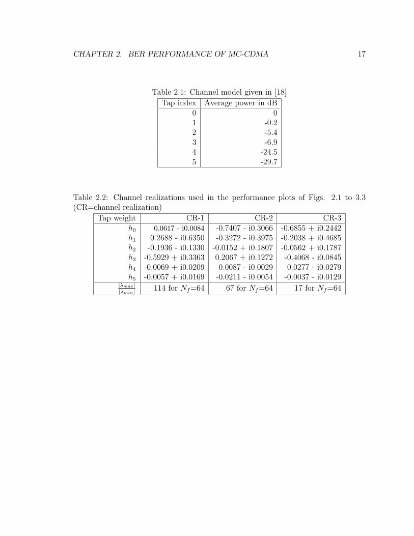
To see if this is the case, we first considered a particular realization of a 6-tap
Rayleigh fading channel model [18] given in Table 2.1, and evaluated the BER perfor-
mance from (2.19) with both MMSE and ZF equalizers for two values of RFO, 0.05
and 0.03, choosing Nf = 64. We may mention here that the channel model considered
here is slightly different from the one given in [18] in that we normalized each tap
variance such that the total variance is one (The variances given in Table 2.1 are not
normalized ones) .

CHAPTER 2. BER PERFORMANCE OF MC-CDMA 16
Figure 2.1 gives the BER plots which support our above remark regarding the
performance of MMSE equalizer, i.e., the performance degrades beyond a threshold
SNR. Note from the plots that for RFO=0.05, the threshold SNR is 28 dB while it
is 33 dB for RFO=0.03. We may point out here that when we considered a partic-
ular channel realization in the analysis, we normalized the channel impulse response
coefficients so as to make it a unit-norm channel. Note that NfP is the average
transmitted signal power in each bin and this prompted us to plot the curves as a
function ofNf P
σ2 .
Next, we considered 3 different realizations of the same 6-tap channel and Figure
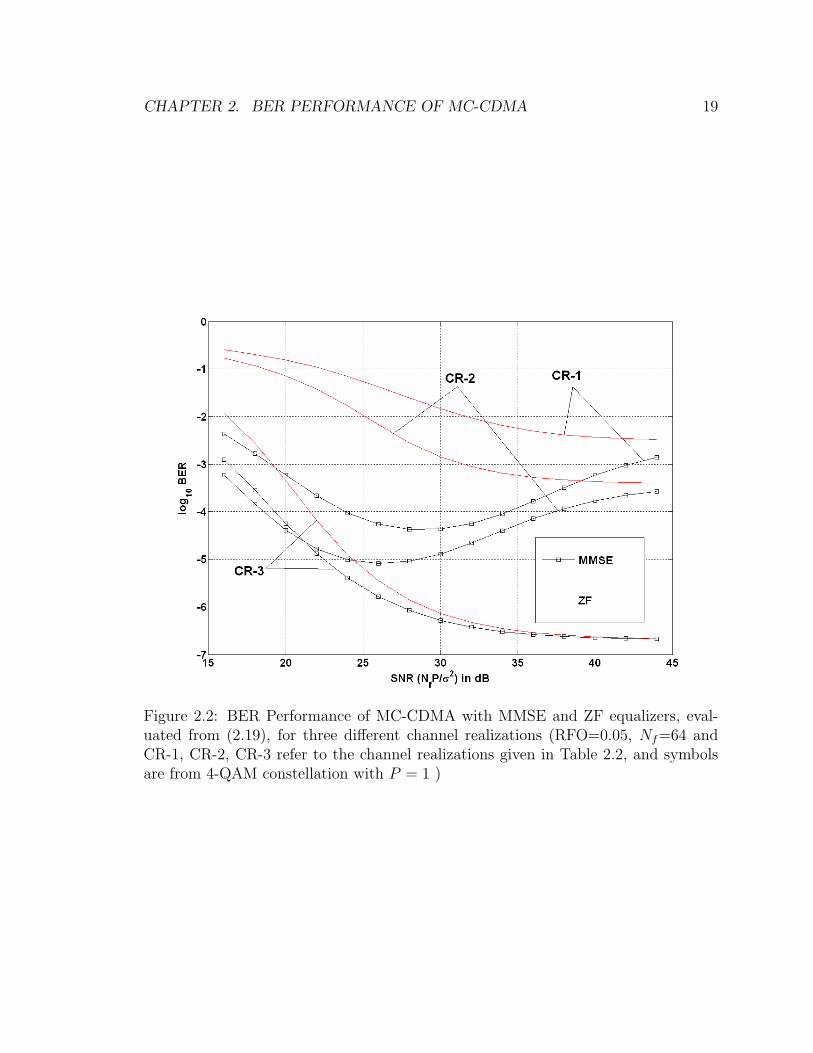
2.2 shows the BER plots for RFO=0.05. Note that the degradation happens for the
channel realizations with large values of |λmax||λmin| (see Table 2.2) where |λmax| and |λmin|
denote, respectively, the largest and smallest of |λ0|, |λ1|, . . . , |λNf−1| and correspond
to the strongest and weakest bin gains, respectively. Note that the threshold SNR in
the case of CR-1 is 28 dB while it is 26 dB for CR-2. We will explain in the next
chapter why the BER performance does not degrade at high SNRs in the case of
channel realization CR-3.
CHAPTER 2. BER PERFORMANCE OF MC-CDMA 17
Table 2.1: Channel model given in [18]
Tap index Average power in dB0 01 -0.22 -5.43 -6.94 -24.55 -29.7
Table 2.2: Channel realizations used in the performance plots of Figs. 2.1 to 3.3(CR=channel realization)
Tap weight CR-1 CR-2 CR-3h0 0.0617 - i0.0084 -0.7407 - i0.3066 -0.6855 + i0.2442h1 0.2688 - i0.6350 -0.3272 - i0.3975 -0.2038 + i0.4685h2 -0.1936 - i0.1330 -0.0152 + i0.1807 -0.0562 + i0.1787h3 -0.5929 + i0.3363 0.2067 + i0.1272 -0.4068 - i0.0845h4 -0.0069 + i0.0209 0.0087 - i0.0029 0.0277 - i0.0279h5 -0.0057 + i0.0169 -0.0211 - i0.0054 -0.0037 - i0.0129
|λmax||λmin| 114 for Nf=64 67 for Nf=64 17 for Nf=64

CHAPTER 2. BER PERFORMANCE OF MC-CDMA 18
Figure 2.1: BER Performance of MC-CDMA with MMSE and ZF equalizers, evalu-ated from (2.19), for RFO=0.05 (plots marked 1) and RFO=0.03 (plots marked 2)(Nf=64 and the channel realization is CR-1 given in Table 2.2, and the symbols arefrom 4-QAM constellation with P = 1)
CHAPTER 2. BER PERFORMANCE OF MC-CDMA 19
Figure 2.2: BER Performance of MC-CDMA with MMSE and ZF equalizers, eval-uated from (2.19), for three different channel realizations (RFO=0.05, Nf=64 andCR-1, CR-2, CR-3 refer to the channel realizations given in Table 2.2, and symbolsare from 4-QAM constellation with P = 1 )
Chapter 3
Cause and Remedy for the
Degradation
The results of the preceding chapter shows that the performance of MC-CDMA with
MMSE equalizer degrades beyond a threshold SNR in multipath channels in the
presence of RFO. In other words, the SINR decreases with increasing SNR beyond
the threshold SNR. We now make an attempt to pinpoint the cause for such behavior.
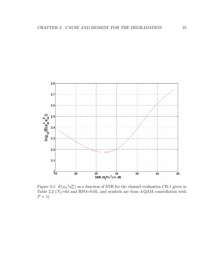
3.1 Cause
Recall that the MMSE equalizer is not designed to combat the ICI which contributes
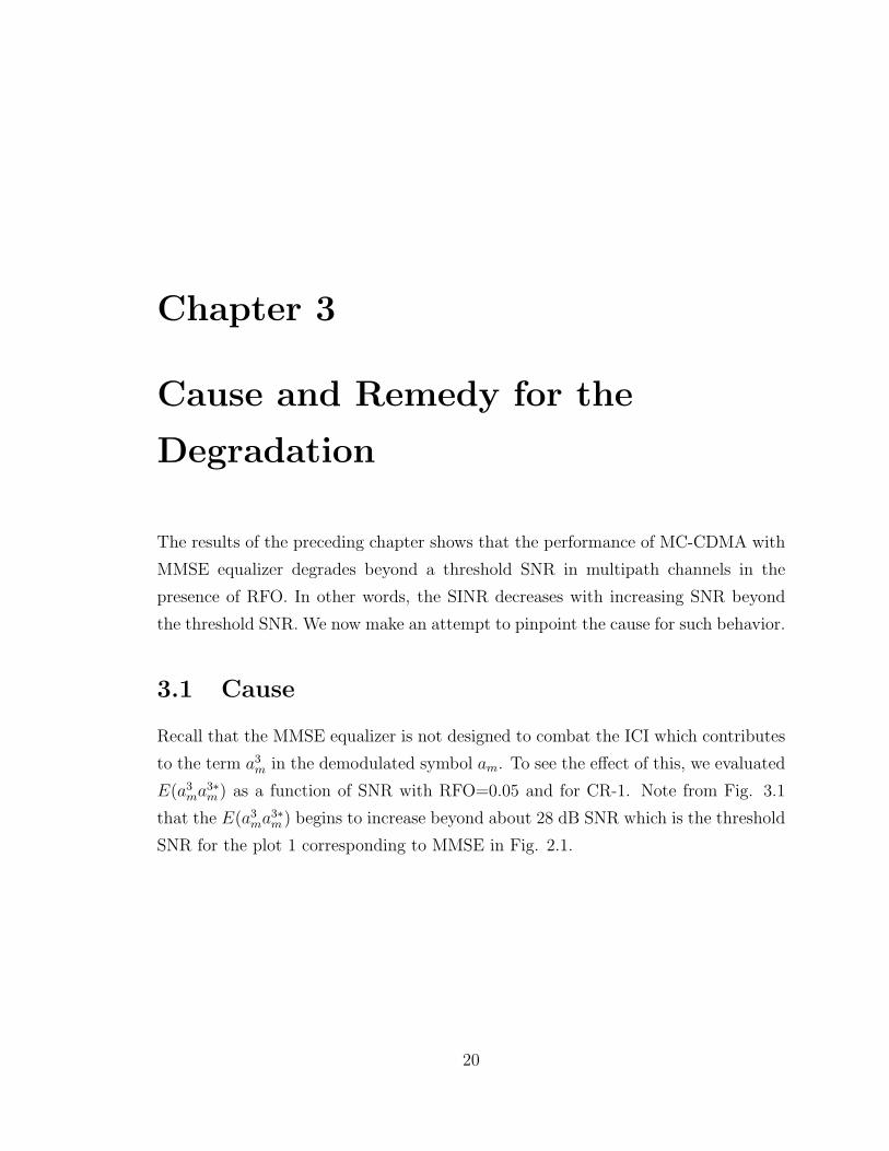
to the term a3m in the demodulated symbol am. To see the effect of this, we evaluated
E(a3ma3∗
m ) as a function of SNR with RFO=0.05 and for CR-1. Note from Fig. 3.1
that the E(a3ma3∗
m ) begins to increase beyond about 28 dB SNR which is the threshold
SNR for the plot 1 corresponding to MMSE in Fig. 2.1.
20

CHAPTER 3. CAUSE AND REMEDY FOR THE DEGRADATION 21
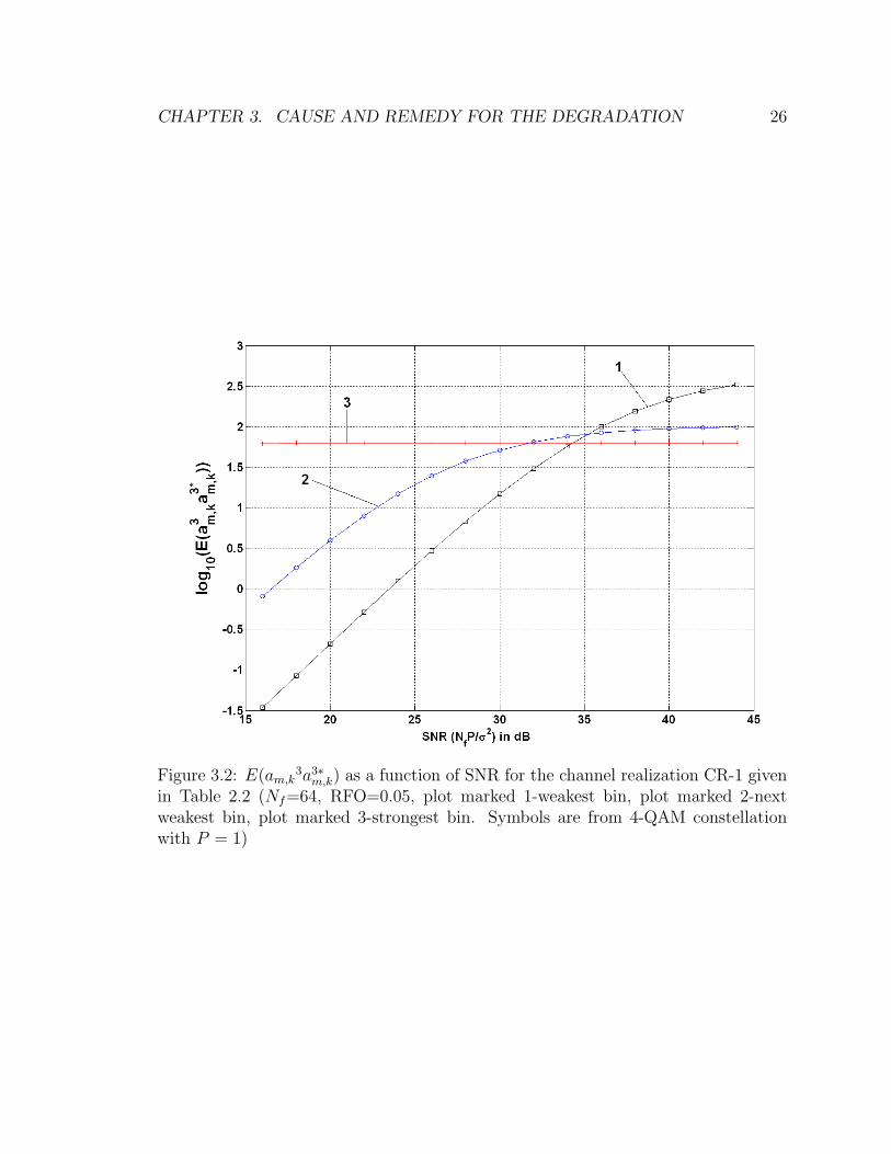
As a3m is the interference from the symbols other than the symbol being decoded
and carried by all the sub-carriers (see (2.16)), we express a3m as
a3m =
Nf−1∑k=0
a3m,k (3.1)
with a3m,k given by
a3m,k =
Nf−1∑l=0,l 6=m
alwTmVk
eq,mmseTΛwl (3.2)
where
Vkeq,mmse = diag [0 · · · 0 Veq,mmse(k, k) 0 · · · 0] (3.3)
Here, a3m,k represents the amount of interference caused by the symbols other than
the symbol being decoded, carried by kth sub-carrier. We now evaluate a3m,k for three
different sub-carriers, one corresponding to the strongest bin (i.e., sub-channel with
largest gain), another corresponding to the weakest bin and the third corresponding
the next weakest bin.
Figure 3.2 gives the plots of E(a3m,ka
3∗m,k) corresponding to these three bins. We
observe the following from the plots. The interference contribution from the strongest
bin (Plot 3) is nearly independent of SNR, while the contribution from the weakest
bin (Plot 1) increases monotonically with SNR, tending to a constant value only at
very large values of SNR. The contribution from the next weakest bin (Plot 2) in-
creases with SNR initially at a slower rate compared to that in the weakest bin case,
and tends to a constant value quickly after the SNR exceeds the threshold value 28
dB. This behavior of the interference contribution from the sub-carriers with varying
gains suggests that it is the weakest bin which essentially determines the degradation
beyond the threshold SNR.
Now, consider the performance of MMSE equalizer in the case of CR-3. We note
from the plots of Fig. 2.2 that the performance of MMSE is not significantly different
from that of ZF at low and moderate SNRs, and consequently, there is no degradation

CHAPTER 3. CAUSE AND REMEDY FOR THE DEGRADATION 22
as in the cases of CR-1 and CR-2. To understand the reasons for this, consider (3.2).
We note from (3.2) that the product of three matrices, Vkeq,mmseTΛ, is a matrix with
all zeros except the kth row, and the elements of this row are Veq,mmse(k, k)T(k, 0)λ0,
Veq,mmse(k, k)T(k, 1)λ1, . . . , Veq,mmse(k, k)T(k,Nf − 1)λNf−1.
Consider the term with k corresponding to the weakest bin and l corresponding to
the strongest bin. This term is of the form (λmin)∗
Nf |λmin|2+ σ2
(P )
λmaxT(k, l). When σ2
(P )is small
compared to Nf |λmin|2, we can approximate the term as λmax
Nf λminT(k, l) which shows
that its contribution depends on the ratio |λmax|/ |λmin|, suggesting that this ratio
plays the role of magnification factor. Thus, the interference contribution from the
symbols (other than the one being decoded) carried by the sub-channels depends on
the spread of sub-channel gains. The low value of this ratio for the channel realization
CR-3 (see Table 2.2) explains why the BER does not degrade as the SNR is increased.
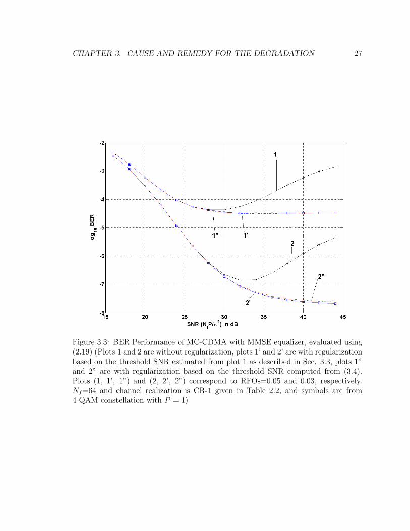
3.2 Remedy
Since the weakest bin determines the degradation, we regularize the corresponding co-
efficient of the equalizer, i.e., Veq,mmse(k, k), k corresponding to λmin, as (λmin)∗
Nf (|λmin|2+( σ2
Nf P)th)
and use the regularized equalizer for the SNRs exceeding the threshold value.
Here, ( σ2
Nf P)th denotes the value of ( σ2
Nf P) at the threshold SNR.
This implicitly assumes that we have the knowledge of the threshold SNR. Before
addressing this issue, we first examine if the suggested regularization prevents the
degradation.
Figure 3.3 gives the BER plots for CR-1 with the equalizer coefficients as given
in (2.11) (plot 1) and with the regularization as suggested above (plot 1’).
In this figure, we chose the value of RFO as 0.05 and Nf = 64, and applied the
regularization with ( σ2
Nf P)th corresponding to the threshold SNR 28 dB.
CHAPTER 3. CAUSE AND REMEDY FOR THE DEGRADATION 23
Note that, as predicted, the regularization prevents the degradation.
Use of above threshold SNR implicitly assumes that we have the knowledge of
RFO value.
In practice, this will not be the case. However, from the system specifications and
the synchronization algorithm, one will have an estimate of the maximum possible
RFO which is of the order 10−2.
It will then be of interest to know how the regularization, computed based on the as-
sumed knowledge of maximum RFO value, will perform if the actual RFO is different
from the assumed.
In Fig. 3.3, Plots 2 and 2’ correspond to the equalizer as given in (2.11) and
the regularized equalizer respectively, for RFO=0.03. We note that the suggested
regularization prevents the degradation even though the actual RFO is different from
the assumed based on which the regularized coefficient were computed. From these
results, we are tempted to state that the knowledge of the actual value of RFO is not
critical to the suggested method.
3.3 Estimating the Threshold SNR
In practical applications, we first perform synchronization and channel estimation
using a pre-amble. From the estimated channel impulse response coefficients, we
compute λk’s. From the knowledge of λk’s and assuming a maximum value for RFO,
and for a given transmitted symbol constellation, we can evaluate BER as a function
of (Nf P
σ2 ) using (2.19). As the precise value of the threshold SNR is not crucial to
the suggested regularization method, a good estimate of this is adequate. Evaluate
the BER over a range of SNR values with a spacing of 2 dB, determine the SNR
at which the BER starts increasing and take the immediate previous SNR value as
the estimate of the threshold SNR ((Nf P
σ2 )th). The range over which the BER is to
be evaluated may be taken large enough, but not very large. Here, the value of
CHAPTER 3. CAUSE AND REMEDY FOR THE DEGRADATION 24
|λmax|/|λmin| can be used as a guideline. If this value is less than Nf , then there is
no need of regularization, and hence, no search is required for the threshold SNR.
3.4 An Approximate Value of Threshold SNR
Recall that in arriving at the regularization coefficient, we assumed (σ2/P ) to be small
compared to Nf |λmin|2 and argued that major contribution to the term a3m comes from
the weakest bin if |λmax|/|λmin| is large. This suggests that an approximate value of
the (Nf P
σ2 )th can be obtained from
(NfP
σ2)th−approx
∼= 3/(|λmin|2) (3.4)
For CR-1 (3.4) gives nearly 23 dB. Note that only the knowledge of CSI is re-
quired in this case.To see how the regularization based on the approximate threshold
SNR performs, we computed this value from (3.4) and regularized the equalizer co-
efficient corresponding to the weakest bin as (λmin)∗
Nf (|λmin|2+( σ2
Nf P)th−approx)
and evaluated
the corresponding BER curves using (2.19). Plots 1” and 2” of Fig. 3.3 show these
results.
The regularization based on the approximate value of the threshold SNR prevents
degradation independent of RFO value and spread in the bin gains. However, at
higher SNRs, there is a small loss in the performance compared to that based on
better estimate of the threshold SNR computed as described in the previous section.
CHAPTER 3. CAUSE AND REMEDY FOR THE DEGRADATION 25
Figure 3.1: E(am3a3∗
m ) as a function of SNR for the channel realization CR-1 given inTable 2.2 (Nf=64 and RFO=0.05, and symbols are from 4-QAM constellation withP = 1)
CHAPTER 3. CAUSE AND REMEDY FOR THE DEGRADATION 26
Figure 3.2: E(am,k3a3∗
m,k) as a function of SNR for the channel realization CR-1 givenin Table 2.2 (Nf=64, RFO=0.05, plot marked 1-weakest bin, plot marked 2-nextweakest bin, plot marked 3-strongest bin. Symbols are from 4-QAM constellationwith P = 1)
CHAPTER 3. CAUSE AND REMEDY FOR THE DEGRADATION 27
Figure 3.3: BER Performance of MC-CDMA with MMSE equalizer, evaluated using(2.19) (Plots 1 and 2 are without regularization, plots 1’ and 2’ are with regularizationbased on the threshold SNR estimated from plot 1 as described in Sec. 3.3, plots 1”and 2” are with regularization based on the threshold SNR computed from (3.4).Plots (1, 1’, 1”) and (2, 2’, 2”) correspond to RFOs=0.05 and 0.03, respectively.Nf=64 and channel realization is CR-1 given in Table 2.2, and symbols are from4-QAM constellation with P = 1)
Chapter 4
Simulation Results
To illustrate how the proposed regularization performs in multipath Rayleigh fading
channels, we conducted simulations using the following simulation set up.
We considered a burst communication in slow fading scenario. Here, we assumed
perfect timing and channel estimate, and assumed a maximum value of RFO as 0.05.
We considered 106 realizations of the channel model given in [18], normalizing each
tap variance such that the total variance is one. This results in the average received
signal power in each bin same as the transmitted power which is NfP . Thus, the
NfP/σ2 represents the received SNR in each bin. The data burst consisted of 100
OFDM symbols where each OFDM symbol was made up of Nf 4-QAM symbols and
mapping of data bits to symbols was based on Gray encoding. A complex Gaussian
noise, with appropriate variance to give the required SNR, was added to the received
signal. The noise corrupted received signal was pre-processed with i) MMSE equalizer
(2.11)), ii) regularized equalizer based on threshold SNR estimated as described in Sec.
3.3 and iii) regularized equalizer based on the approximate threshold SNR computed
from (3.4). In each case, for different values of NfP/σ2, the pre-processed received
signal was decoded and the number of decoded symbols in error was noted. This was
repeated for 106 channel realizations, choosing a different sequence of transmitted 4-
QAM symbols and a different noise sequence in each case, and the number of decoded
symbols in error was noted. From the results so obtained, the average symbol error
probability was computed for each value of NfP/σ2, and one half of this was taken
28
CHAPTER 4. SIMULATION RESULTS 29
as the BER.
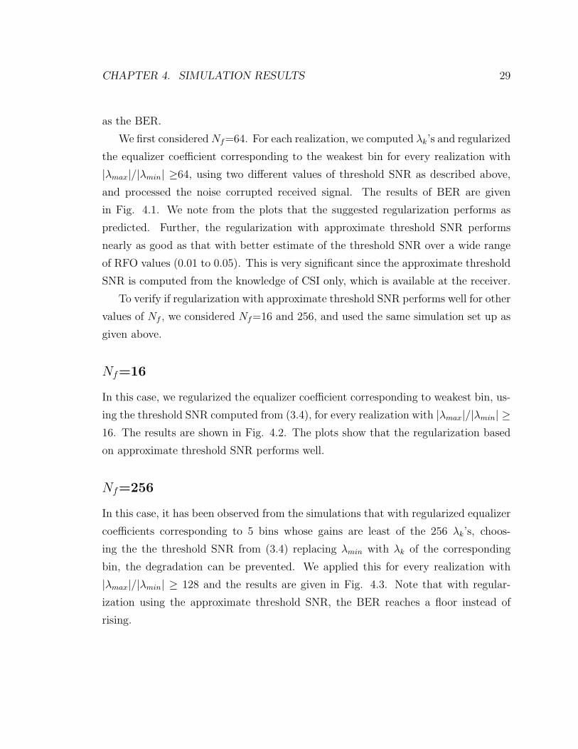
We first considered Nf=64. For each realization, we computed λk’s and regularized
the equalizer coefficient corresponding to the weakest bin for every realization with
|λmax|/|λmin| ≥64, using two different values of threshold SNR as described above,
and processed the noise corrupted received signal. The results of BER are given
in Fig. 4.1. We note from the plots that the suggested regularization performs as
predicted. Further, the regularization with approximate threshold SNR performs
nearly as good as that with better estimate of the threshold SNR over a wide range
of RFO values (0.01 to 0.05). This is very significant since the approximate threshold
SNR is computed from the knowledge of CSI only, which is available at the receiver.
To verify if regularization with approximate threshold SNR performs well for other
values of Nf , we considered Nf=16 and 256, and used the same simulation set up as
given above.
Nf=16
In this case, we regularized the equalizer coefficient corresponding to weakest bin, us-
ing the threshold SNR computed from (3.4), for every realization with |λmax|/|λmin| ≥16. The results are shown in Fig. 4.2. The plots show that the regularization based
on approximate threshold SNR performs well.
Nf=256
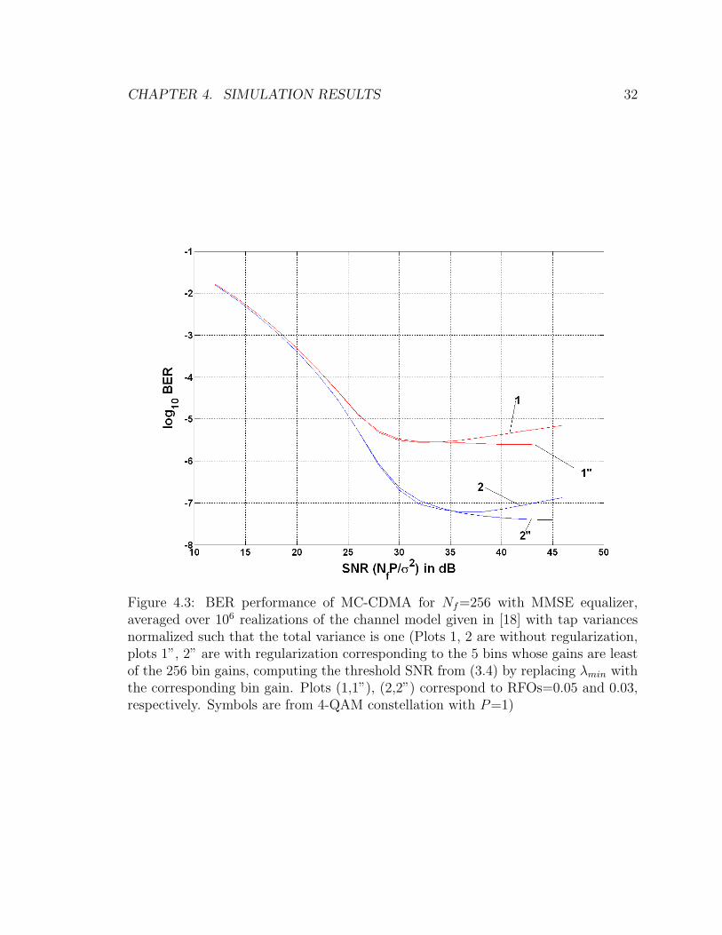
In this case, it has been observed from the simulations that with regularized equalizer
coefficients corresponding to 5 bins whose gains are least of the 256 λk’s, choos-
ing the the threshold SNR from (3.4) replacing λmin with λk of the corresponding
bin, the degradation can be prevented. We applied this for every realization with
|λmax|/|λmin| ≥ 128 and the results are given in Fig. 4.3. Note that with regular-
ization using the approximate threshold SNR, the BER reaches a floor instead of
rising.
CHAPTER 4. SIMULATION RESULTS 30
Figure 4.1: BER performance of MC-CDMA for Nf=64 with MMSE equalizer, av-eraged over 106 realizations of the channel model given in [18] with tap variancesnormalized such that the total variance is one (Plots 1, 2, 3 are without regular-ization, 1’, 2’, 3’ are with regularization based on the threshold SNR estimated asgiven in Sec. 3.3 with RFO=0.05, plots 1”, 2”, 3” are with regularization basedon the threshold SNR computed from (3.4). Plots (1,1’,1”), (2,2’,2”) and (3,3’,3”)correspond to RFOs=0.05, 0.03 and 0.01, respectively. Symbols are from 4-QAMconstellation with P=1)

CHAPTER 4. SIMULATION RESULTS 31
Figure 4.2: BER performance of MC-CDMA for Nf=16 with MMSE equalizer, av-eraged over 106 realizations of the channel model given in [18] with tap variancesnormalized such that the total variance is one (Plots 1, 2 are without regulariza-tion, plots 1”, 2” are with regularization based on the threshold SNR computed from(3.4). Plots (1,1”), (2,2”) correspond to RFOs=0.05 and 0.03, respectively. Symbolsare from 4-QAM constellation with P=1)
CHAPTER 4. SIMULATION RESULTS 32
Figure 4.3: BER performance of MC-CDMA for Nf=256 with MMSE equalizer,averaged over 106 realizations of the channel model given in [18] with tap variancesnormalized such that the total variance is one (Plots 1, 2 are without regularization,plots 1”, 2” are with regularization corresponding to the 5 bins whose gains are leastof the 256 bin gains, computing the threshold SNR from (3.4) by replacing λmin withthe corresponding bin gain. Plots (1,1”), (2,2”) correspond to RFOs=0.05 and 0.03,respectively. Symbols are from 4-QAM constellation with P=1)
Chapter 5
Conclusions
In this thesis, we have studied the BER performance of MC-CDMA with MMSE
equalizer in the presence of RFO in multipath Rayleigh fading channels, and brought
out the threshold effect, i.e., beyond certain SNR the BER deteriorates, and the
value of this SNR depends on the value of RFO and multipath channel profile. An
attempt has been made to pinpoint the cause for such behavior and a remedy has been
suggested to prevent the deterioration in the BER values. To implement the remedy,
knowledge of the threshold SNR is needed which in turn requires the knowledge of
RFO and CSI. It is shown that with an approximate value of the threshold SNR,
which can be computed from the knowledge of CSI only, deterioration in the BER
performance can be prevented. Numerical and simulation results are provided to
support the analysis.
5.1 Future Work
It would be interesting to investigate the performance of MC-CDMA systems with
Gold codes which are preferred for uplink MC-CDMA systems over Walsh Hadamard
codes and also study the MIMO MC-CDMA performance in the presence of RFO.
33
Appendix A
Derivation of MMSE Equalizer for
MC-CDMA
In practice, we will not have the knowledge of the exact value of RFO, and hence, we
design the equalizer only to combat MCI. With RFO as zero (i.e, ε = 0) (2.8) can be
written as
r = Λx + η (A.1)
For convenience, we repeat (1.4) here
x =
Nf−1∑k=0
wkak = Wa (A.2)
where a = [a0 a1 . . . aNf−1]T . Combining (A.1) with (A.2), we have
r = ΛWa + η (A.3)
Let Veq,mmse denote the MMSE equalizer matrix. With ε = 0, (2.10) can be
written as
am = wTmVeq,mmseΛWa + wT
mVeq,mmseη (A.4)
34
APPENDIX A. DERIVATION OF MMSE EQUALIZER FOR MC-CDMA 35
Denote the error in am and am as
em = am − am (A.5)
Using the principle of orthogonality [24], we have
E (em∗r) = 0Nfx1 (A.6)
The above equation can be re-written as
E(emrH
)= 01xNf
(A.7)
Using (A.3) and (A.5), (A.7) can be expressed as
E((
wTmVeq,mmseΛWa + wT
mVeq,mmseη − am
)(ΛWa + η)H
)= 01xNf
(A.8)
The symbols ak’s are independent and identically distributed (i.i.d) and the η is a
circularly symmetric complex Gaussian noise vector of size Nfx1 with i.i.d elements,
each having zero mean and variance σ2. Simplifying (A.8) we get
wTmVeq,mmse
(NfΛΛH +
σ2
PI
)−wT
mΛH = 01xNf(A.9)
which can be re-written as
wTmVeq,mmse = wT
mΛH
(NfΛΛH +
σ2
PI
)−1
(A.10)
From (A.10), the MMSE equalizer is obtained as
Veq,mmse = ΛH
(NfΛΛH +
σ2
PI
)−1
(A.11)
Since Λ is a diagonal matrix, Veq,mmse is a diagonal matrix with the diagonal

APPENDIX A. DERIVATION OF MMSE EQUALIZER FOR MC-CDMA 36
elements given by
Veq,mmse(m,m) =(λm)∗
Nf |λm|2 + σ2
(P )
, 0 ≤ m ≤ Nf − 1 (A.12)
Bibliography
[1] J.A.C. Bingham, “Multicarrier modulation for data transmission: An idea whose
time has come”, IEEE Communications Magazine, vol. 28, pp. 5-14, May 1990
[2] K. Fazel and S. Kaiser, Multi-Carrier and Spread Spectrum Systems, Wiley series
2003.
[3] Y Zhou, J Wang and M Sawashashi, “Downlink transmission of broadband
OFCDM systems-part 1: Hybrid detection.” IEEE Transactions on Commu-
nications Vol 53 N0.4 April, 2003.
[4] N. Yee, J.P. Linnartz and G. Fettweis, “Multi-carrier CDMA in indoor wireless
radio network”, Proc. PIMRC ’93, pages 109-113, Vol. 1, 1993.
[5] M. Speth, S.A. Fechtel, G. Fock and H. Meyr, “Optimum receiver design for
wireless broadband systems using OFDM-part1”, IEEE Transactions on Com-
munications, vol. 47,no 11, pp. 1668-1677, 1999.
[6] Ch. Nanda Kishore and V. U. Reddy, “A frame synchronization and frequency
offset estimation algorithm for OFDM system and its analysis”, Eurasip Journal
on Wireless Communications and Networking, vol 2006, Article ID 57018, Pages
1-16.
[7] J.-J. van de Beek, M. Sandell, M. Isaksson and P.O. Borjesson, “Low-complex
frame synchronization in OFDM systems”, in Proceedings of IEEE Internatial
Conference Universal Personal Communications, Toronto, Canada, Sept. 2729,
1995, pp. 982986.
37
BIBLIOGRAPHY 38
[8] P. H. Moose, “A technique for orthogonal frequency division multiplexing fre-
quency offset correction”, IEEE Transactions on Communications, vol. 42, no
10, Oct 1994.
[9] H. Minn, V. Bhargava, and K. Letaief, “A robust timing and frequency synchro-
nization for OFDM systems”, IEEE Transactions on Wireless Communications,
vol. 2, pp. 822-839, 2003.
[10] T. M. Schmidl and D. C. Cox, “Robust frequency and timing synchronization for
OFDM”, IEEE Transactions on Communications, vol. 45,no 12, pp. 1613-1621,
1997
[11] L. Rugini and P. Banelli, “BER of OFDM systems impaired by carrier frequency
offset in multipath fading channels”, IEEE Transactions on Wireless Communi-
cations, vol. 4, no 5, pp. 2279-2288, September 2005.
[12] Y Kim, S. Choi, C. You and D. Hong, “BER computation of an MC-CDMA
system with carrier frequency offset” in ICASSP 1999 pp. 2555-2558.
[13] J. Jang and K. Bok Lee, “Effects of frequenct offset on MC/CDMA systems
perofrmance”, IEEE Communications Letters vol. 3 no. 7, pp. 196-198 July 1999.
[14] Chung-Liang Chang, P. Sheng Huang and Te-Ming Tu, “Performance comparison
of MRC and EGC on an MC-CDMA system with synchronization errors over
fading channels”, Wireless Personal Communications , Vol 43 , Pages: 685 - 698,
2007.
[15] Y. Nasser, M. des Noes, L. Ros and G. Jourdain, “Sensitivity of multicarrier
two-dimensional spreading schemes to synchronization errors”, Eurasip Journal
on Wireless Communications and Networking , vol 2008, Article ID 561869.
[16] T. Pollet, M. Van Bladel, and M. Moeneclaey, “BER sensitivity of OFDM sys-
tems to carrier frequency offset and Wiener phase noise”, IEEE Transactions on
Communications, vol. 43, no 234, pp. 191-193, Feb/Mar/Apr. 1995
BIBLIOGRAPHY 39
[17] N. Yee and Jean-Paul Linnartz, “Wiener filtering of multi-carrier CDMA in
Rayleigh fading channels”, WCN, PIMRC 1994
[18] K. Pahlavan and Allen H. Levesque, Wireless Information Networks, second
edition, Wiley Interscience 2005.
[19] J. Proakis, Digital Communications, third edition, McGraw-Hill 1995.
[20] R. S. Ahmad Bahai and R. Burton Saltzberg, Multi-Carrier Digital
Communications-Theory and Applications of OFDM, Plenum Publishers 1999.
[21] David Tse and Pramod Viswanath, Fundamentals of Wireless Communication,
Cambridge University Press 2005.
[22] A. Papoulis, Probability, Random Variables and Stochastic Processes, MCGraw-
Hill, 1965.
[23] Nanda Kishore. C, An improved frame synchronization and frequency offset es-
timation algorithm for OFDM based system with application to wireless MAN,
M.S. Thesis, IIIT-Hyderabad, June 2005.
[24] B. Farhang-Boroujney, Adaptive Filters-Theory and Applications, Wiley Series
1998.


![ISSN 1751-8628 BER analysis of space–time …youssef/Publications...Other related works on the performance of STC in DS-CDMA systems include [11–18]. In a MIMO CDMA with large](https://static.fdocuments.us/doc/165x107/5ecad03348d9b46d755fe344/issn-1751-8628-ber-analysis-of-spaceatime-youssefpublications-other-related.jpg)