Beniamino Barbieri
48
Fluorescence Microscopy Beniamino Barbieri I am greatly indebted for this presentation to Professor Enrico Gratton.
Transcript of Beniamino Barbieri

Fluorescence Microscopy Beniamino Barbieri I am greatly indebted for this presentation to Professor Enrico Gratton.

type feature appearance uses
Bright-field Visible light Colored/clear specimen
Light background
Stained specimen with sufficient
color contrast
Dark-field Visible light Bright specimen
Dark background
Unstained or difficult to stain
specimen
Phase contrast Visible light / phase shifting Different degrees of brightness
and darkness internal structure of specimen
Differential Interference
contrast Visible light out of phase Nearly 3D image
Fine details of internal structure of
unstained specimen
Fluorescence UV-IR light Fluorescence specimen
Detection of molecules,
organisms, antibodies in clinical
specimens
Transmission Electron
Microscope Electron beam / magnetic lens High magnification Internal structures; viruses
Scanning Electron
Microscope Electron beam 3D view of surfaces
External or internal surfaces of
cells
Scanning Tunneling Wire probe over surfaces 3D view of surfaces Observation of external surfaces
of atoms or molecules
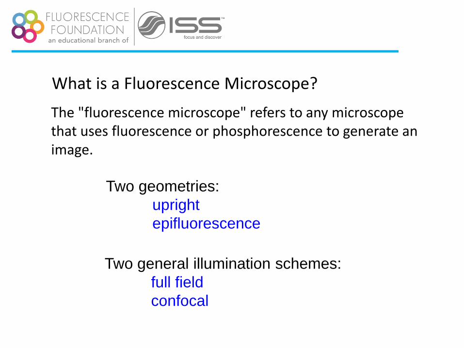
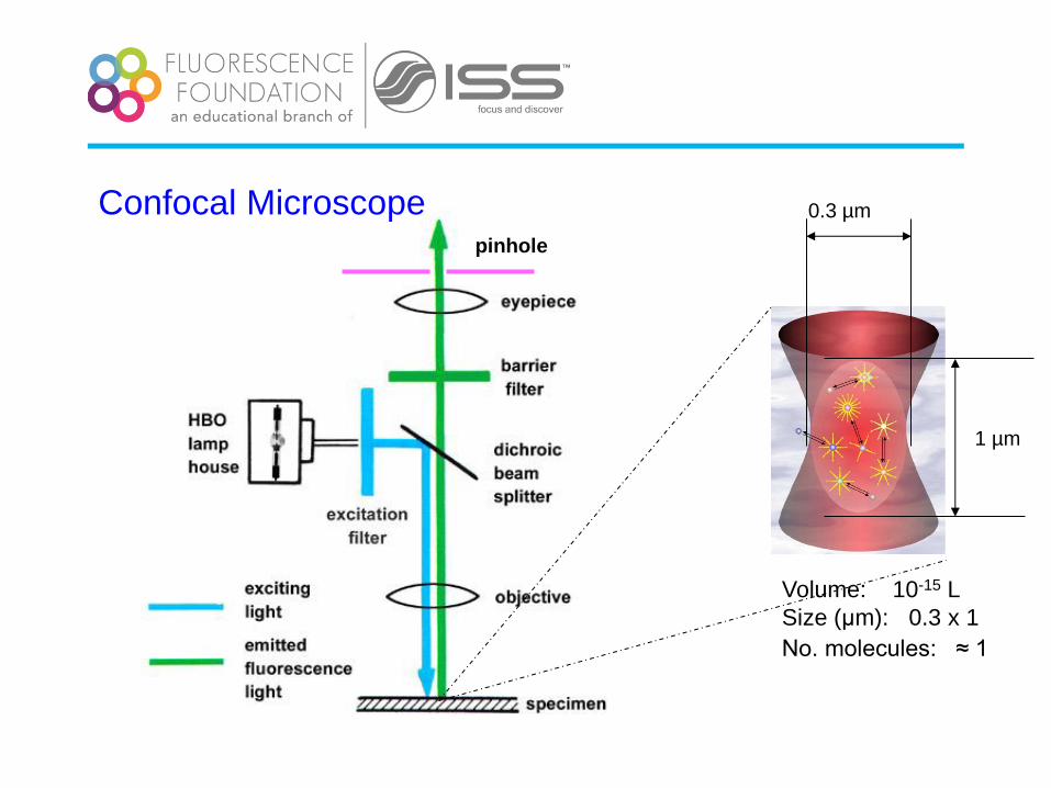
What is a Fluorescence Microscope?
The "fluorescence microscope" refers to any microscope that uses fluorescence or phosphorescence to generate an image.
Two geometries:
upright
epifluorescence
Two general illumination schemes:
full field
confocal

pinhole
1 µm
0.3 µm
Volume: 10-15 L
Size (μm): 0.3 x 1
No. molecules: ≈ 1

Frits Zernike The Nobel Prize in Physics 1953
On looking back to this event, I am impressed by
the great limitations of the human mind. How
quick we are to learn – that is, to imitate what
others have done or thought before – and how
slow to understand – that is, to see the deeper
connections. Slowest of all, however, we are in
inventing new connections or even in applying
old ideas in a new field.

Light Source Optics Light Detector
Sample
A typical microscopy setup

Light Source Optics Light Detector
Sample
A typical microscopy setup

The Microscope
• Structure
• Objectives
• Koehler illumination
• Slides and coverslips
• Contrast and
resolution
Confocal Microscope
• PSF
• Multiphoton excitation
Fluorescence Microscope

Olympus BH2 cutaway Diagram
From http://micro.magnet.fsu.edu/primer/anatomy/specifications.html
From http://micro.magnet.fsu.edu/primer/anatomy/specifications.html
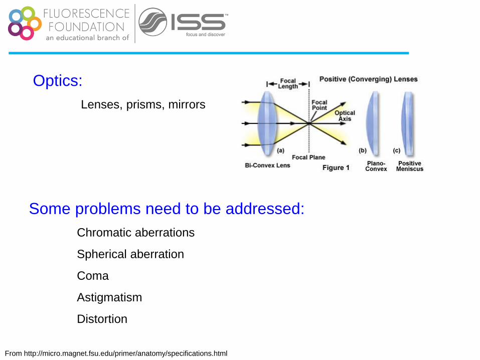
Optics:
Lenses, prisms, mirrors
Some problems need to be addressed:
Chromatic aberrations
Spherical aberration
Coma
Astigmatism
Distortion

From http://micro.magnet.fsu.edu/primer/anatomy/specifications.html
A few useful parameters:
sinNA n
1/ #
2
ff
D NA
When a lens forms the image of an extended object, the amount of energy
collected from a small area of the object is 1) directly proportional to the
area of the clear aperture, or entrance pupil, of the lens. 2) At the image,
the illumination (power per unit area) is inversely proportional to the
image area over which this object is spread. The aperture area is
proportional to the square of the pupil diameter, and the image area is
proportional to the square of the image distance, or square of the focal
length
Why are they useful?
Numerical
aperture
F-number
From http://micro.magnet.fsu.edu/primer/anatomy/specifications.html
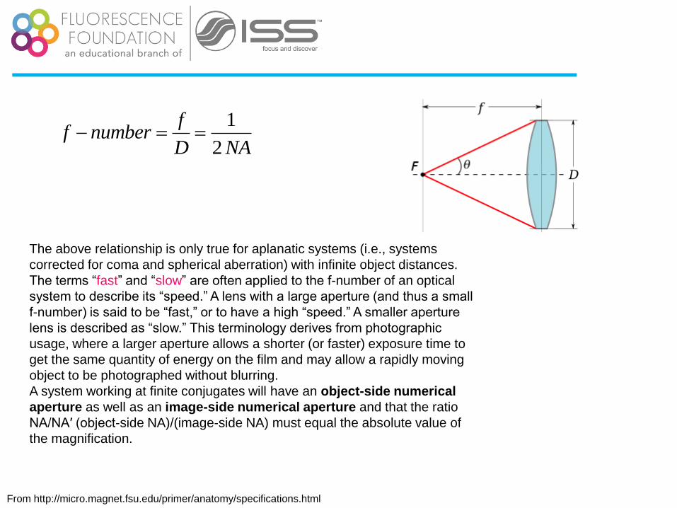
1
2
ff number
D NA
The above relationship is only true for aplanatic systems (i.e., systems
corrected for coma and spherical aberration) with infinite object distances.
The terms “fast” and “slow” are often applied to the f-number of an optical
system to describe its “speed.” A lens with a large aperture (and thus a small
f-number) is said to be “fast,” or to have a high “speed.” A smaller aperture
lens is described as “slow.” This terminology derives from photographic
usage, where a larger aperture allows a shorter (or faster) exposure time to
get the same quantity of energy on the film and may allow a rapidly moving
object to be photographed without blurring.
A system working at finite conjugates will have an object-side numerical
aperture as well as an image-side numerical aperture and that the ratio
NA/NA′ (object-side NA)/(image-side NA) must equal the absolute value of
the magnification.

From http://micro.magnet.fsu.edu/primer/anatomy/specifications.html
Resolution of optical systems
When a bright point source of light is imaged, an Airy disk with a perfect
lens, encircling rings appear in the image plane. The distance from the
center of the Airy disk to the first dark ring is “z”:
1.22
2z
NA
From http://micro.magnet.fsu.edu/primer/anatomy/specifications.html
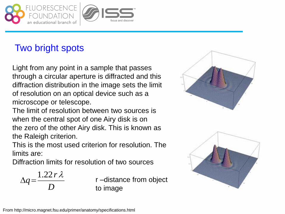
Two bright spots
Light from any point in a sample that passes
through a circular aperture is diffracted and this
diffraction distribution in the image sets the limit
of resolution on an optical device such as a
microscope or telescope.
The limit of resolution between two sources is
when the central spot of one Airy disk is on
the zero of the other Airy disk. This is known as
the Raleigh criterion.
This is the most used criterion for resolution. The
limits are:
Diffraction limits for resolution of two sources
1.22r
qD
r –distance from object
to image

From ED Salmon
Contrast All the resolution in the world won’t do you any good, if there is no
contrast to visualize the specimen.
1 2 3 4 5 6 7 8 9 1 0
C O N T R A S T = ( Is p - Ib g) / Ib g
H I G H L O W

The object is far away
The object is at 2f from the
lens. The image is at 2f
beyond the focal length; it
has the same size as the
object, it is real and inverted
The object is at 2f <O<1.5f
from the lens. The image
is magnified, inverted and
real.
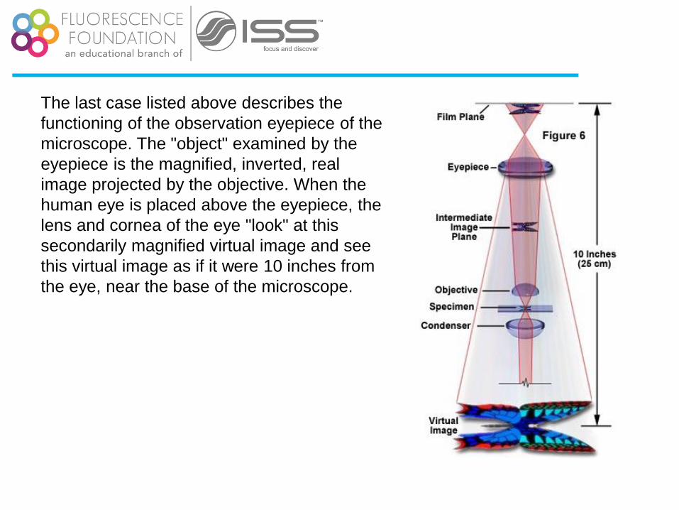
The last case listed above describes the
functioning of the observation eyepiece of the
microscope. The "object" examined by the
eyepiece is the magnified, inverted, real
image projected by the objective. When the
human eye is placed above the eyepiece, the
lens and cornea of the eye "look" at this
secondarily magnified virtual image and see
this virtual image as if it were 10 inches from
the eye, near the base of the microscope.
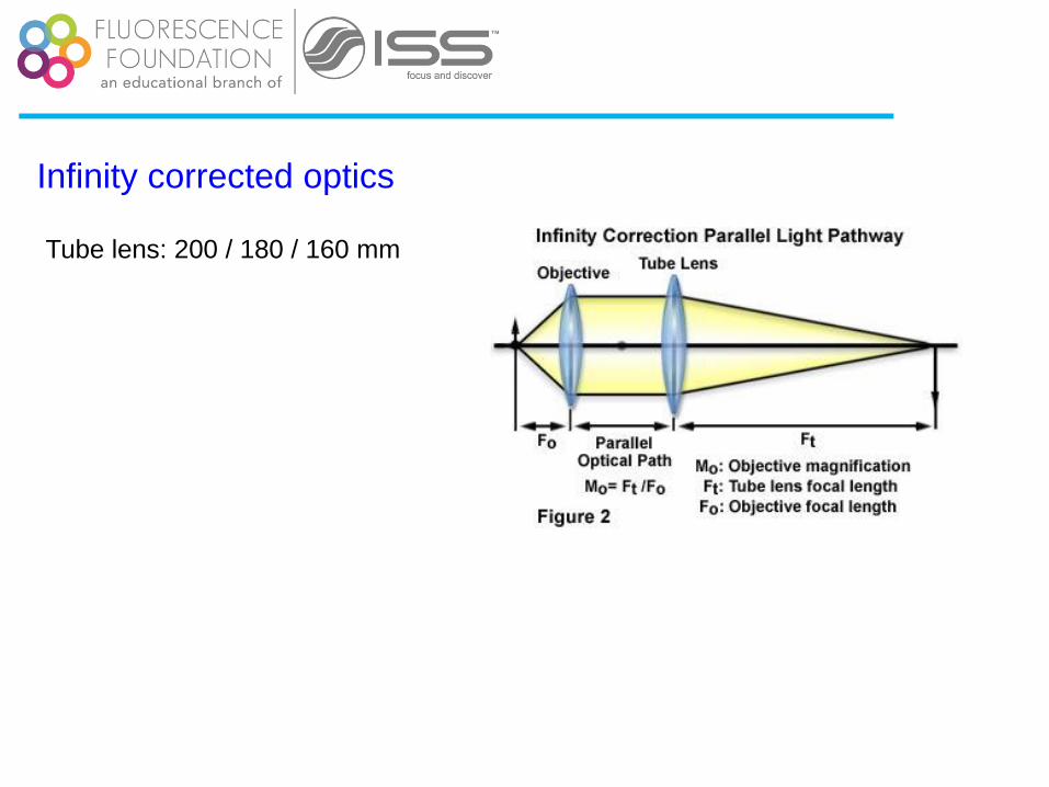
Infinity corrected optics
Tube lens: 200 / 180 / 160 mm
From http://micro.magnet.fsu.edu/primer/anatomy/specifications.html
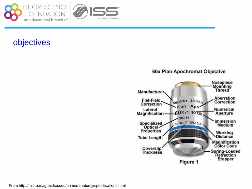
objectives
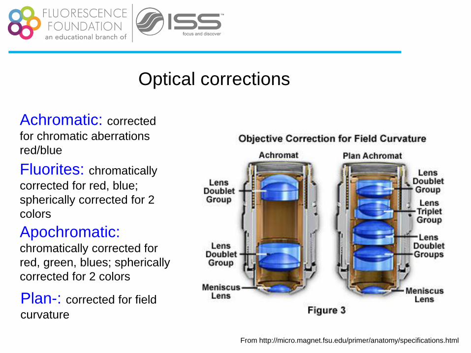
Optical corrections
Achromatic: corrected
for chromatic aberrations
red/blue
Fluorites: chromatically
corrected for red, blue;
spherically corrected for 2
colors
Apochromatic: chromatically corrected for
red, green, blues; spherically
corrected for 2 colors
Plan-: corrected for field
curvature
From http://micro.magnet.fsu.edu/primer/anatomy/specifications.html

Resolution is better at shorter wavelengths, higher objective NA or
higher condenser NA
High NA and/or shorter λ Low NA and/or longer λ
From ED Salmon
1.22 0.61
2 sinr
n NA

Rayleigh Criterion for the resolution of two adjacent spots:
Plim = 0.61 o / NAobj
Examples: (o = 550 nm)
Mag f(mm) n a NA Plim (mm) (NAcond=NAobj)
high dry 10x 16 1.00 15 0.25 1.10
40x 4 1.00 40 0.65 0.42
oil 100x 1.6 1.52 61 1.33 0.204
63x 2.5 1.52 67.5 1.40 0.196

Köhler illumination
Courtesy of Dr. Peter So
The image of the
source is not focused
on the specimen
Light sources:
Tungsten lamp
Halogen lamp
Mercury
LEDs
Lasers
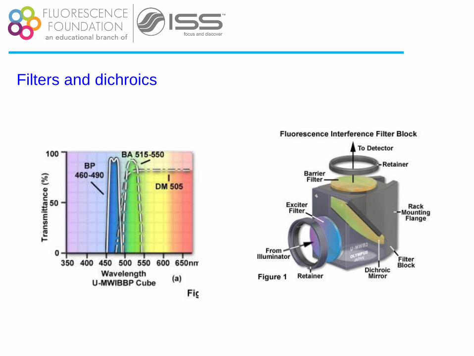
Filters and dichroics
Courtesy of Dr. Peter So
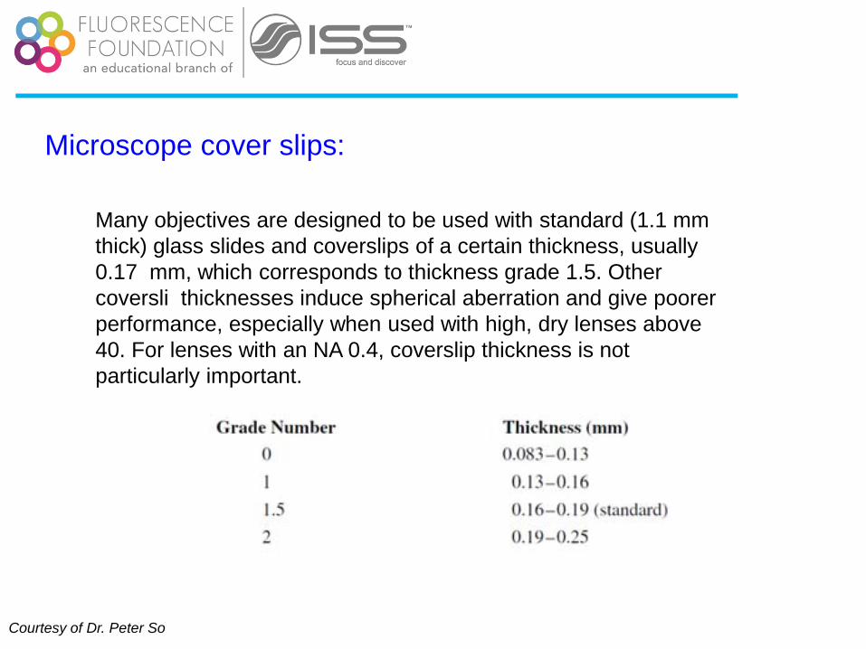
Microscope cover slips:
Many objectives are designed to be used with standard (1.1 mm
thick) glass slides and coverslips of a certain thickness, usually
0.17 mm, which corresponds to thickness grade 1.5. Other
coversli thicknesses induce spherical aberration and give poorer
performance, especially when used with high, dry lenses above
40. For lenses with an NA 0.4, coverslip thickness is not
particularly important.
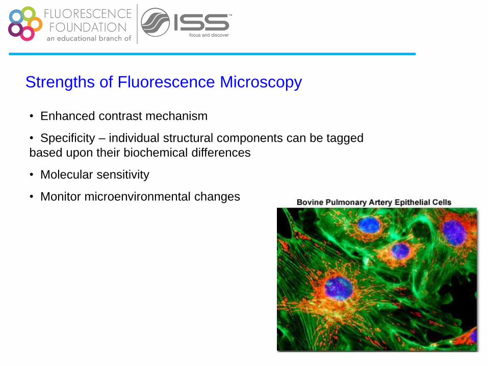
Strengths of Fluorescence Microscopy
• Enhanced contrast mechanism
• Specificity – individual structural components can be tagged
based upon their biochemical differences
• Molecular sensitivity
• Monitor microenvironmental changes

Confocal microscopy, early demonstrations
White et al., 1987

Confocal microscopy; more comparisons
(a) and (b) Mouse brain hippocampus thick section treated with primary antibodies to glial fibrillary acidic
protein (GFAP; red), neurofilaments H (green), and counterstained with Hoechst 33342 (blue) to highlight
nuclei.
(c) and (d) Thick section of rat smooth muscle stained with phalloidin conjugated to Alexa Fluor 568
(targeting actin; red), wheat germ agglutinin conjugated to Oregon Green 488 (glycoproteins; green), and
counterstained with DRAQ5 (nuclei; blue).
(e) and (f) Sunflower pollen grain tetrad autofluorescence.
Comparison of widefield
(upper row) and laser
scanning confocal
fluorescence microscopy
images (lower row). Note
the significant amount of
signal in the widefield
images from
fluorescent structures
located outside of the focal
plane.
From R. Clegg lectures
pinhole
1 µm
0.3 µm
Volume: 10-15 L
Size (μm): 0.3 x 1
No. molecules: ≈ 1
Confocal Microscope
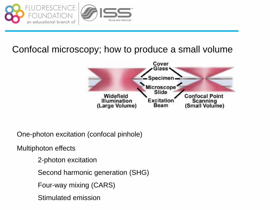
Confocal microscopy; how to produce a small volume
One-photon excitation (confocal pinhole)
Multiphoton effects
2-photon excitation
Second harmonic generation (SHG)
Four-way mixing (CARS)
Stimulated emission

Light Source Optics Light Detector
Sample
A typical microscopy setup
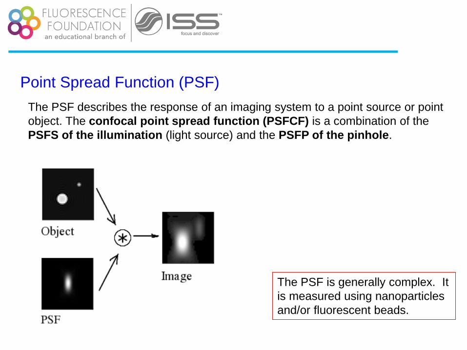
Point Spread Function (PSF)
The PSF describes the response of an imaging system to a point source or point
object. The confocal point spread function (PSFCF) is a combination of the
PSFS of the illumination (light source) and the PSFP of the pinhole.
The PSF is generally complex. It
is measured using nanoparticles
and/or fluorescent beads.

Point Spread Function (PSF) for the source
2
0
22 )(2
0 )(,,w
yx
ezIIzyxF
2
0
22)(
zw
zExpzI
2)(1
1)(
ozw
zzI
z-Gaussian
z-Lorentzian
The PSF is generally complex. It
is measured using nanoparticles
and/or fluorescent beads.
Laser beam profile

PSF
a. widefield
b. 2-photon
a. 1-photon w/ pinhole
Optical conditions: excitation
wavelengths are 488 nm and 900 nm for
1PE and 2PE, respectively; emission
wavelength is 520 nm; numerical
aperture is 1.3 for an oil immersion
objective with oil refractive index value
set at 1.515.
Diaspro et al.; BioMedical Engineering OnLine 5:36, 2006

Deconvolution techniques
is the acquired image, o the object acquired, h the PSF and N the noise.
' ' ' ' ' ' ' ' '( , , ) ( ( , , ) ( , , , , , ) )i x y z N O x y z h x y z x y z dx dy dz

Resolution in Confocal microscopy
The maximum resolution that can be achieved
using light of wavelength λ is given by: )sin(2
nr
For =500nm, n=1.5 and =45degrees r=236nm
NA can be as large as 1.50, so that a resolution of λ/3 can be achieved!
We call super-resolution any method that goes beyond the Abbe’s limit
(Abbe limit)

Two photon excitation
1-photon 2-photon
Since two-photon absorption is a second-order process involving the almost
Simultaneous interaction of two photons with one fluorophore, this process
has a small cross-section, on the order of 10-50 cm4 s (defined as 1GM,
Göppert-Mayer).

Lasers for two-photon excitation
For a δ2 of approximately 10 GM, focusing through an objective of
NA >1, an average incident laser power of ≈ 1–50 mW, operating at a
wavelength ranging from 680 to 1100 nm with 80–150 fs pulse width
and 80–100 MHz repetition rate, one should get fluorescence without
saturation.
na, is the probability that a certain
fluorophore simultaneously absorbs two
photons during a single pulse; in the
paraxial approximation this is given by
2 22
2 2a
p p
P NAn
hcf

Design of a two photon microscope
From Peter So lectures
Two-photon microscope design is
actually significantly simpler than
that of confocal microscope and
has much in common.

Separation of excitation and emission
exc em
400 800 nm
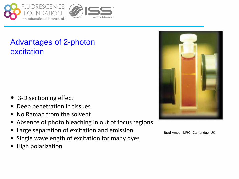
Advantages of 2-photon
excitation
Brad Amos; MRC, Cambridge, UK
• 3-D sectioning effect
• Deep penetration in tissues • No Raman from the solvent • Absence of photo bleaching in out of focus regions • Large separation of excitation and emission • Single wavelength of excitation for many dyes • High polarization
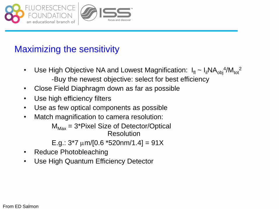
Maximizing the sensitivity
• Use High Objective NA and Lowest Magnification: Ifl ~ IilNAobj4/Mtot
2
-Buy the newest objective: select for best efficiency
• Close Field Diaphragm down as far as possible
• Use high efficiency filters
• Use as few optical components as possible
• Match magnification to camera resolution:
MMax = 3*Pixel Size of Detector/Optical Resolution
E.g.: 3*7 mm/[0.6 *520nm/1.4] = 91X
• Reduce Photobleaching
• Use High Quantum Efficiency Detector
From ED Salmon
Confocal microscopy

Confocal microscopy


Confocal microscopy

Thank you.