Benefits of SFRA - Case · PDF fileBenefits of SFRA - Case Studies 1 ... LV MAGNETIC BALANCE...
42
Benefits of SFRA - Case Studies 1 6 th International Conference on Large Power Transformers- Modern Trends B B Ahir Gujarat Energy Transmission Corporation Limited
Transcript of Benefits of SFRA - Case · PDF fileBenefits of SFRA - Case Studies 1 ... LV MAGNETIC BALANCE...

Benefits of SFRA - Case Studies
1
6th International Conference on Large Power
Transformers- Modern Trends
B B Ahir
Gujarat Energy Transmission Corporation Limited

Outline
Condition Monitoring in GETCO
Why SFRA ?
Case study (1):SFRA - How it helped to find a fault in winding
Case study (2): SFRA - How it helped to find a fault in core
Case study (3): SFRA - How it helped to find a fault in core
Conclusion
2

Condition Monitoring in GETCO
3
Technology / Tool Online Offline
Insulation Resistance and Polarisation Index √
Routine Low Voltage tests √
Capacitance & Tan δ measurements √(Bushing)
√
Infrared Thermograph √
Measurement of Moisture in Oil √ √
DGA √ √
SFRA √
Acoustic Partial Discharge √
Measurement moisture content in active parts of Transformer √
Transformer
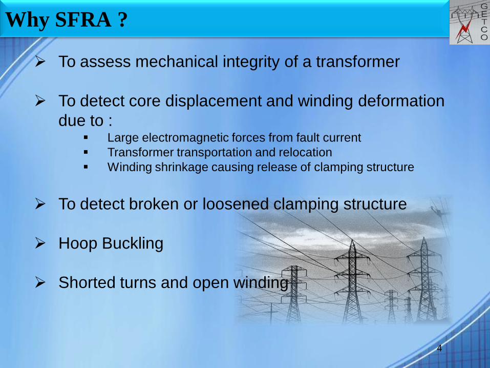
Why SFRA ?
4
To assess mechanical integrity of a transformer
To detect core displacement and winding deformation
due to : Large electromagnetic forces from fault current
Transformer transportation and relocation
Winding shrinkage causing release of clamping structure
To detect broken or loosened clamping structure
Hoop Buckling
Shorted turns and open winding

Case study (1):
5
Location : 220 kV Kapadwanj S/s
Rating : 220/66kV, 100 MVA
Date : 22.01.2012
Initially SFRA along with Low Voltage Test and DGA
OSR relay operated due to LV side Isolator support insulator flash over
Case study (1):
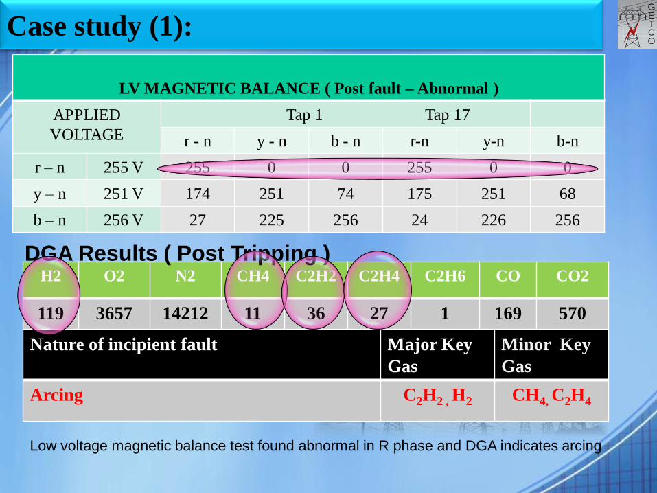
LV MAGNETIC BALANCE ( Post fault – Abnormal )
APPLIED
VOLTAGE
Tap 1 Tap 17
r - n y - n b - n r-n y-n b-n
r – n 255 V 255 0 0 255 0 0
y – n 251 V 174 251 74 175 251 68
b – n 256 V 27 225 256 24 226 256
H2 O2 N2 CH4 C2H2 C2H4 C2H6 CO CO2
119 3657 14212 11 36 27 1 169 570
DGA Results ( Post Tripping )
Nature of incipient fault Major Key
Gas
Minor Key
Gas
Arcing C2H2 , H2 CH4, C2H4
Low voltage magnetic balance test found abnormal in R phase and DGA indicates arcing

Case study (1):
7
HV – N at Tap No.1 ( Post fault - Abnormal)
500Hz to 2MHz with +/- 3 dB: Tap and Main winding
HV R
Phase
HV R phase shifted -3dB with reference to other phase in main and tap winding portion

Case study (1):
8
LV – N at Tap No.17 ( Post fault - Abnormal)
500Hz to 2MHz with +/- 3 dB: Tap and Main winding
LV R
Phase
20Hz – 10KHz – Core
deformation/open ckt./
Shorted turns / residual
magnetism
LV R phase shifted widely with reference to other phase in main and tap winding portion.
It seems like open circuit.

Case study (1):
9
SFRA LV R phase found abnormal – defect in
tapped winding ( 500Hz to 2 MHz) and open
winding ( 5Hz to 100kHz ) with +/- 3 dB
variation.
Problem reflected in low voltage magnetic
balance and DGA ( Arcing ) also.
Based on above abnormal results, decided to
internal inspection of this transformer.
Analysis

Case study (1): Internal Inspection
10
LV R phase connecting leads of preselector switch of OLTC and its fixing
assembly burnt.
Burnt link and fixing assembly replaced
Re-insulation of leads
Drying process with oil filtration
Take SFRA and other supporting test
Burned connecting leads

Case study (1):
11
HV – N at Tap No.1 ( Normal – After rectification )
HV R
Phase
All phases are identical after rectification of problem

Case study (1):
12
LV – N at Tap No.17 ( Normal – After rectification)
LV R
Phase
All phases are identical after rectification of problem

Case study (1):
LV MAGNETIC BALANCE ( Normal – After rectification )
APPLIED
VOLTAGE
Tap 1 Tap 17
r - n y - n b - n r-n y-n b-n
r – n 255 V 255 224 30 255 225 25
y – n 252 V 176 252 76 175 252 69
b – n 255 V 28 226 255 26 226 255
Low voltage test found normal after rectification

Case study (1):
14
Cause of failure
The heavy fault current due to flash over of LV side
isolator support insulator caused R phase pre-selector
switch LV connection two nos. of leads between
position 3 & 12 to burn.
SFRA plays a role as a supporting test to confirm the
fault with other test.

Case study (2):
15
Location : 220kV Khanpur Substation
Rating : 220/66kV , 100 MVA
Date : 21.04.08
High key gases in routine DGA test
Low voltage test - √

Case study (2):
16
DGA Results ( on 22.12.07 , Normal )
H2 O2 N2 CH4 C2H2 C2H4 C2H6 CO CO2
7 3405 12150 21 Nil 48 15 34 292
Nature of incipient fault Major Key
Gas
Minor Key
Gas
Thermal Fault - Over heated oil CH4, C2H4 C2H6 , H2
H2 O2 N2 CH4 C2H2 C2H4 C2H6 CO CO2
355 2988 13928 472 <1 538 214 57 1085
DGA Results ( on 21.04.08 , Abnormal )
DGA indicates thermal fault as per high key gases method
Case study (2): Low voltage Test
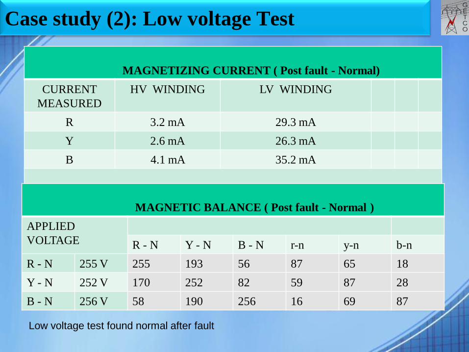
MAGNETIZING CURRENT ( Post fault - Normal)
CURRENT
MEASURED
HV WINDING LV WINDING
R 3.2 mA 29.3 mA
Y 2.6 mA 26.3 mA
B 4.1 mA 35.2 mA
MAGNETIC BALANCE ( Post fault - Normal )
APPLIED
VOLTAGE R - N Y - N B - N r-n y-n b-n
R - N 255 V 255 193 56 87 65 18
Y - N 252 V 170 252 82 59 87 28
B - N 256 V 58 190 256 16 69 87
Low voltage test found normal after fault

Case study (2): Low voltage Test
SHORT CIRCUIT CURRENT ( Post fault - Normal )
CURRENT
MEASURED
HV WINDING LV WINDING
R 3.54 A 10.38 A
Y 3.55 A 10.18 A
B 3.48 A 10.41 A
Low voltage test found normal after fault

19
HV - N ( Post fault - Abnormal)
Case study (2):
20Hz – 10KHz – Core
deformation/open ckt./
Shorted turns / residual
magnetism
HV B Phase
B phase curve differ in core area in compare with other two phases which shows core
related issue

Case study (2):
20
HV - N ( LV Shorted ) ( Post fault - Abnormal )
HV B Phase
LV short curve nullify effect of core, winding part seems identical and normal

Case study (2):
21
LV – N ( Post fault - Abnormal)
LV B Phase
20Hz – 10KHz – Core
deformation/open ckt./
Shorted turns / residual
magnetism
B phase curve differ in core dominated area, which shows problem in core area

Case study (2):
22
SFRA showed abnormality in the core.
IR between core , frame and earth was measured.
Core to Frame : 2000MΩ
Frame to Earth : 8000MΩ
Core to Earth : 0.03MΩ
As the Core to Earth insulation found quite low, internal
inspection carried out but nothing seen abnormal.
Further investigation was done by inserting a GI wire
between core and bottom of the tank and along the core
nut found under the B phase core limb which was
touching core and bottom.
Analysis

Case study (2): Schematic Diagram
23

Case study (2): Analysis
24
After removing the nut, again IR between core , frame
and earth was measured.
Core to Frame : 2000MΩ
Frame to Earth : 8000MΩ
Core to Earth : 2000MΩ
Normally core earthing provided on top of the tank. The
nut was providing another earthing and it caused thermal
fault due to circulating current between core and earth.

25
HV - N ( Normal – After rectification)
Case study (2):
After attending the problem all phase curves found identical
Case study (2):
26
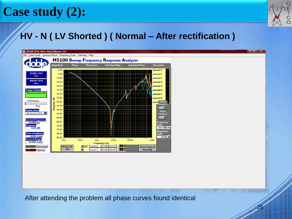
HV - N ( LV Shorted ) ( Normal – After rectification )
After attending the problem all phase curves found identical

Case study (2):
27
LV – N ( Normal – After rectification)
After attending the problem all phase curves found identical

Case study (2):
28
Conclusion
A metallic nut below the core at bottom of the tank was
found out with the help of SFRA which created parallel
path to earth and led to thermal fault.
Such kind of unbelievable fault can be identified by
SFRA.
In this case SFRA played a vital role as a supporting tool
with DGA to detect the faulty area and to reach up to the
root cause of the fault.

Case study (3):
29
Location : 66kV Chhala Substation
Rating : 66/11.55kV , 10 MVA
Date : 01.09.08
Tripped on differential relay due to failure of 66kV class
Y phase bushing with reflected of 11kV feeder
Case study (3): Low voltage Test
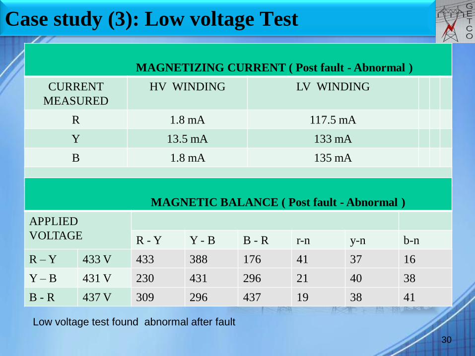
MAGNETIZING CURRENT ( Post fault - Abnormal )
CURRENT
MEASURED
HV WINDING LV WINDING
R 1.8 mA 117.5 mA
Y 13.5 mA 133 mA
B 1.8 mA 135 mA
30
MAGNETIC BALANCE ( Post fault - Abnormal )
APPLIED
VOLTAGE R - Y Y - B B - R r-n y-n b-n
R – Y 433 V 433 388 176 41 37 16
Y – B 431 V 230 431 296 21 40 38
B - R 437 V 309 296 437 19 38 41
Low voltage test found abnormal after fault

31
HV PH – PH ( Post fault - Abnormal )
Case study (3):
20Hz – 10KHz – Core
deformation/open ckt./
Shorted turns / residual
magnetism
Y-BR-Y B-R
All three phases response are differ in core related area as mentioned frequency

32
HV PH – PH ( LV Shorted ) ( Post fault – Normal )
Case study (3):
In LV short condition core area nullify and winding area curves are identical in all
phases

33
LV PH – N ( Post fault - Abnormal )
Case study (3):
20Hz – 10KHz – Core
deformation/open ckt./
Shorted turns / residual
magnetism
R Y B
All three phases response are differ in core related area as mentioned frequency

Case study (2): Analysis
34
SFRA and low voltage revealed problem inside core
area.
Internal inspection carried out by removing top plate of
transformer.
2 Nos. of bolts clamping the top channel with tank were
loose and top yoke channel got lifted upwards by about
25mm which caused a little core deformation.
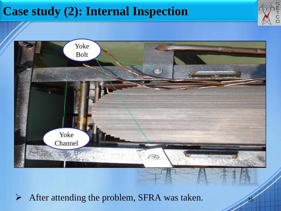
Case study (2): Internal Inspection
35 After attending the problem, SFRA was taken.
Yoke
Bolt
Yoke
Channel
36
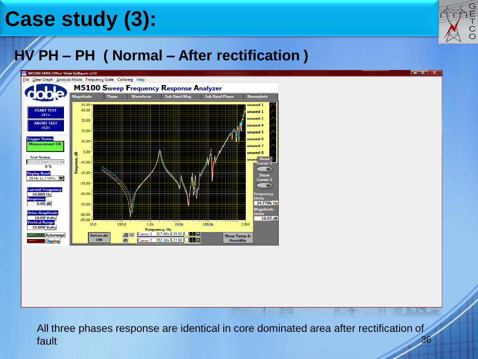
HV PH – PH ( Normal – After rectification )
Case study (3):
All three phases response are identical in core dominated area after rectification of
fault

37
HV PH – PH ( LV Shorted ) ( Normal – After rectification )
Case study (3):
This response was identical from initially as problem was in core area after rectification
of fault

38
LV PH – N ( Normal – After rectification )
Case study (3):
All three phases response are identical now in core area after rectification of fault

Case study (3): Low voltage Test
MAGNETIC BALANCE ( Normal – After rectification)
APPLIED
VOLTAGE R - Y Y - B B - R r-n y-n b-n
R – Y 442 V 442 365 79 41 35 6
Y – B 450 V 256 450 189 23 42 17
B - R 445 V 44 396 445 4 37 41
39
MAGNETIZING CURRENT ( Normal – After rectification)
CURRENT
MEASURED
HV WINDING LV WINDING
R 2.4 mA 56.2 mA
Y 1.9 mA 28.5 mA
B 2.2 mA 55.6 mA
Low voltage test found normal after rectification of fault

Case study (3):
40
Cause of Failure
Heavy reflected fault caused axial and radial forces
exerted on transformer active part.
Core structure got disturbed and it was reflected in SFRA
plot.
Conclusion
41
SFRA responses clearly indicate faulty conditions of transformer and it
helped for root cause analysis.
SFRA helps to detect fault by just compare with different phase with
different task without having a initial results of same transformer or
same design transformer.
SFRA plays vital role as supporting test for final conclusion as its
deliver diversity of information in only one test.
SFRA is very useful tool to detect heavy through fault current leads to
mechanical deformation of core or winding, internal connections and
contacts inside transformer.
GETCO has adopted such diagnosis tool while fault as well as in
routine practice while shifting of transformer.

Thanks………
42