BENEFICIATION DESCRIPIION -...
21
SAND BENEFICIATION PROCESS DESCRIPIION
Transcript of BENEFICIATION DESCRIPIION -...

SAND BENEFICIATION PROCESS DESCRIPIION

CHAPTER-2
SAND BENEFICIATION PROCESS DESCRIPTION
2.1 GENERAL
Silica (quartz) sand is used in glass manufacture. Quartz comprises '50-65% of the mix used to. make glass. The high purity of
dune sand makes it especially useful in glass manufacturing. The
quality of sand used for glass making is highly restrictive.
Specifications for glass sands generally require a specific range of
grain sizes which produce even melting. Chemically, the sands must
be over 98% pure silica and contain practically no impurities,
especially metallic oxides. As little as 0.001% metallic oxides will
impart colour to glass. Most glass companies prefer to have nearly
pure silica sand (99.5% or greater purity) to which they will add their
own desired special ingredients. This is particularly true in the case
of optical glass, which has very high silica and very low metal oxide
content.
2.1.1 SILICA SAND MINING
The activity of mining and quarrying covers underground and
surface mines, quarries and wells involving extraction of minerals and
also all the supplemental activities such as dressing and benefaction
of ores, crushing, screening, washing, cleaning, grading, milling,
floatation, melting and other preparations carried out at the mine site
which are needed to render the material marketable,
The mining activities in the country are governed by the Mineral
Conservation Development Rules (MCDR) 1988. Every license holder
of mining, lease shall take all possible precautions for protection of
environment and control of pollution while conducting prospecting,
mining, beneficiation or metallurgical operations in the area. Specific
provisions for proper removal and utilization of top soil, storage of over
burden and waste rocks, reclamation and rehabilitation of lands,
precautions against air pollution, noise and ground vibrations,
restoration of flora, discharge of toxic liquid, control of surface
subsidence have been provided under the MCDR. The Indian Bureau
of Mines collects the statistics on all these aspects under the above
rules.
2.1.2 SAND BENEFICIATION
,'
After the ore containing the desired material has been brought
to the surface, it is generally necessary to separate the wanted from
the unwanted constituents, and to create a more uniformly sized
material for subsequent processing. Such operations, collectively
referred to as beneficiation, are often carried out near the extraction
point, to minimize transport of low-value materials.
Beneficiation processes primarily directed towards resizing
include:
Milling (crushing, grinding)
Sizing (screening, centrifugation)
Consolidation (sintering, palletizing, brique'tting)
Beneficiation processes carried out with the object of removing
impurities or concentrating desired material include:
Wet processes
o Washing
o Leaching
o Flotation

o Dissolution or solvent extraction, followed by crystallization
or precipitation
o Filtration
o Electrowinning
o Ion exchange
Thermal processes
o Calcining
o Roasting
o Autoclaving
o Drying
Magnetic and electrostatic separation
The sand beneficiation process followed at the plant site near
Tada, under study, consists of the five distinguished steps:
Removal of trash/weeds or lumps (> 3 mm size) by scalping
vibrating screens.
Removal of over size (> 630 p) and under size (< 100 11 size)
sands by the principle of hindered settlement with water jets.
Attrition and washing with water to separate fines and clay
which is adhered to the sand particles.
Heavy mineral separation through the principle of density
separation from the sand in the spirals. Heavy minerals having
a specific gravity of greater than 2.6 will get separated from
sand having a specific gravity of 2.6.
Dewatering of the treated sand in a vibrating screen down to
15% moisture.
2.2 LOCATIOI AND ACCESSIBILITY OF THE INDUSTRY
The glass manufacturing industry of M / s . Saint Gobain India
Ltd., has the following components:
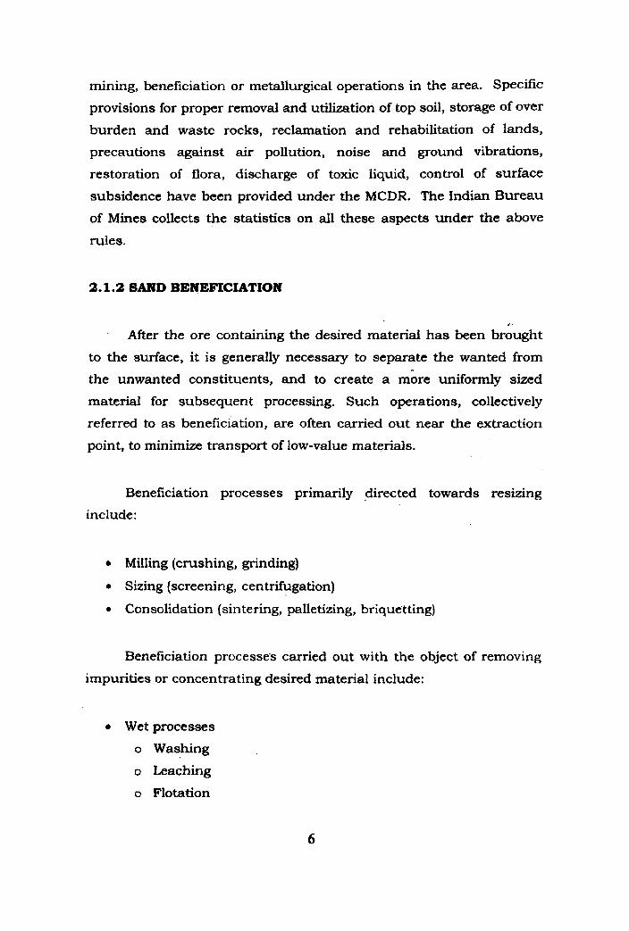
1. Silica Sand Minors: Silica sand is available in the mines
of Chintavaram, Ballavolu, Momidi, Yeruru and
Vellapalem situated at a distance of about 26 km from Gudur town, in Nellore district of Andhra Pradesh state.
2. Sand beneficiation plant: Sand beneficiation plant is
located at Karuru village in Tada Industrial Area (TIA) of
Nellore district of Andhra Pradesh state.
3. Float glasa factory: Float glass manufacturing unit, "the
Float" is located at Sriperumbudur town in Chengai-Anna
district of Tamil Nadu state, which is situated at a
distance of 60 km west-south west of Chennai.
The present study is concentrated on the application of EIA over
the sand mining area near Gudur and the sand beneficiation plant
situated near Tada.
2.2.1 Silica Sand Mines
Silica sand is available in the mines of Chintavaram, Ballavolu,
Momidi, Yeruru and Vellapalem situated about 26 krn from Gudur.
Gudur is on the Kolkata-Chennai National Highway No. 5
approximately 70 km from the sand beneficiation plant site at Tada
and 135 km from Chennai. The location map of the silica sand mines
is shown in Fig. 2.1.

lJ' ANDHRA PRADESH
Fig. 2.1 .loeation of Silica b d Mine8
9
2.2.2 Sand Beneficiation Plant
The sand beneficiation plant site is located at K a r u r u village,
Tada Industrial Area set up by Andhra Pradesh Industrial
Infrastructure Corporation (APIIC). The Industrial Development
Area (IDA) falls under Nellore district of Andhra Pradesh and is
actually located in the border of Nellore and Chittoor districts. Tada
Industrial Area (TIA) is located 5 krn south of Tada town and
approximately 60 krn from Chennai, adjacent to National Highway
No. 5 connecting C henna. and Kolkata.
The site is located approximately 70 krn from sand mining area
and 115 krn from float glass factory at Sriperumbudur, Tamil Nadu.
The sand beneficiation plant is 10 m above Mean Sea Level ( MSL ).
Total rainfall in the area is 1260 mm per annum, of which 770 mm
occurs during peak monsoon i,e., during October to December
months. The wind speed at Tada is considered same as in Chennai
which is 50 m/s as per IS 875. Tada comes under zone I1 for earth
quakes with a seismic coefficient of 0.02 as per IS 1893- 1984.
The area of the plant site is having non-uniform silty sand of l m
thickness on top followed by clayey sand. The location map of the
sand beneficiation plant is shown in Fig. 2.2.
2.3 DETAILS OF PLANT LAYOUT
The details of plant layout are shown in Fig. 2.3.

fig. 2.2 h t i o n Map of the Sand kneflciatbn Piant
11
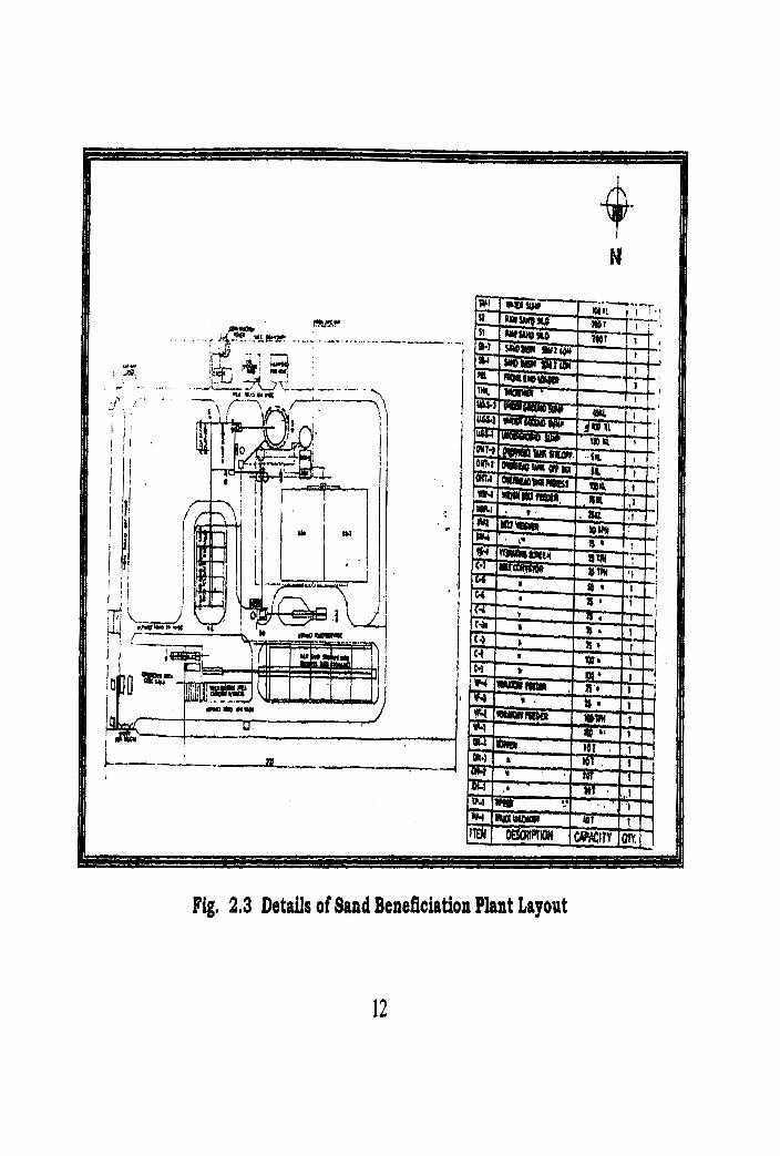
Fig, 2.3 Details of Sand Beneficiation Plant Layout
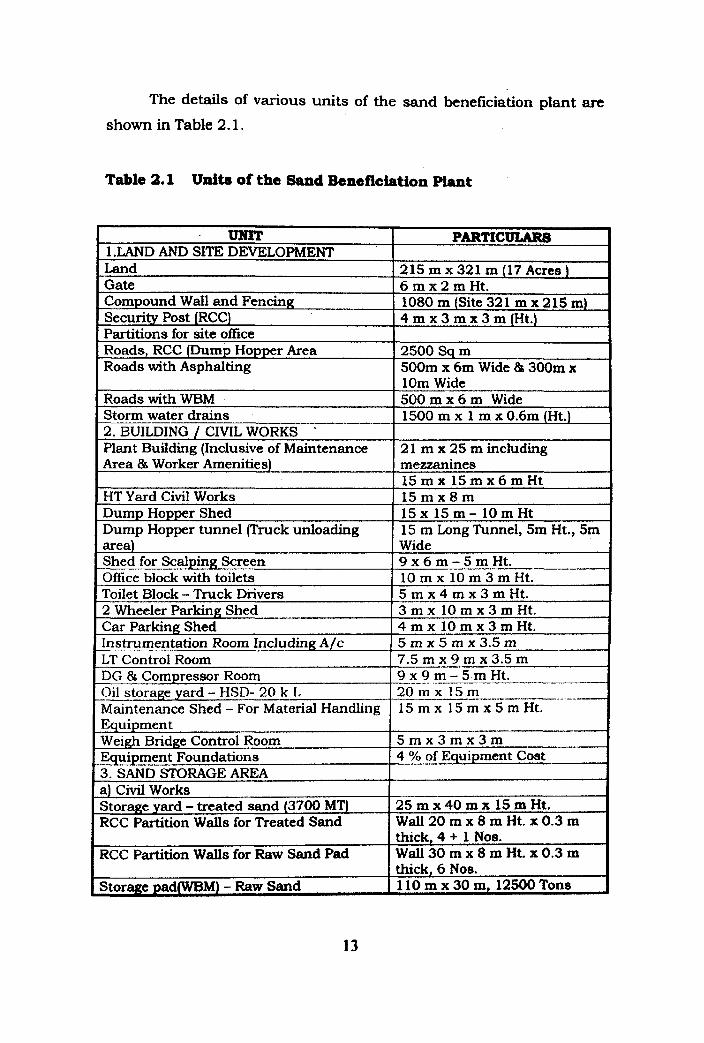
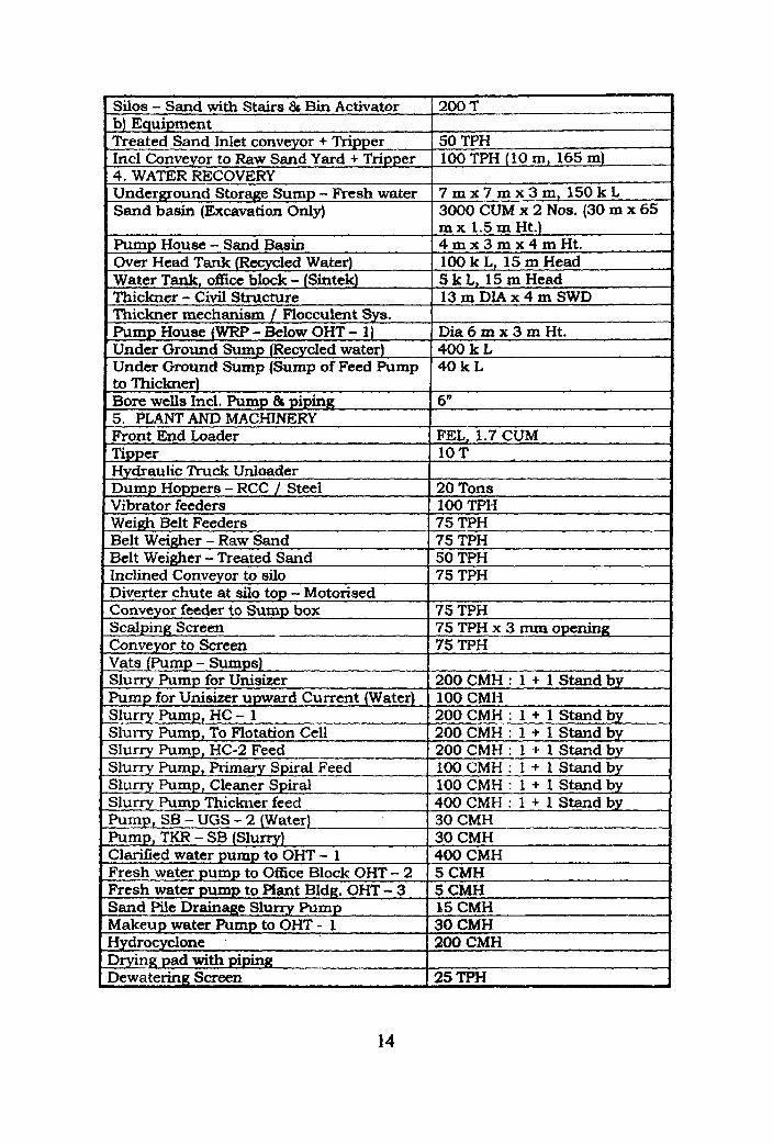
The details of various units of the sand bencficiation plant are
shown in Table 2.1.
Table 2.1 Units of the Sand Beneficiation Plant
UNIT 1 .LAND AND SITE DEVELOPMENT Land Gate Compound Wall and Fencing Security Post (RCC) Partitions for site office Roads, RCC (Dump Hopper Area Roads with Asphalting
Roads with WBM Storm water drains 2. BUILDING / CIVIL WORKS .
Plant Building (Inclusive of Maintenance Area & Worker Amenities)
HT Yard Civil Works Dump Hopper Shed Dump Hopper tunnel (Truck unloading area) Shed for Scalping Screen Office block with toilets Toilet Block - Truck Drivers 2 Wheeler Parking Shed Car Parking Shed Instrumentation Room Including A/c LT Control Room DG & Compressor Room Oil storage yard - HSD- 20 k L Maintenance Shed - For Material Handling Equipment Weigh Bridge Control Room Equipment Foundations 3. SAND STORAGE AREA a) Civil Works Storage yard - treated sand (3700 MT) RCC Partition Walls for Treated Sand
RCC Partition Walls for Raw Sand Pad
Storage pad(WBM) - Raw Sand
PARTICULAR8
215 m x 321 m (17 Acres) 6 m x 2 m H t . 1080 m (Site 32 1 m x 2 15 m) 4 m x 3 m x 3 m ( H t . )
2500 Sq m 500m x 6m Wide % 300m x 1Om Wide 500 m x 6 m Wide 1500 m x 1 m x 0.6m (Ht.)
21 m x 25 m including mezzanines 1 5 m x 1 5 m x 6 m H t 1 5 m x 8 m 15x 1 5 m - 10mHt 15 m Long Tunnel, 5m Ht., 5m Wide 9 x 6 m - 5 m H t . 10 m x 10 m 3 m Ht. 5 m x 4 m x 3 m H t . 3 m x 1 0 m x 3 m H t . 4 m x 1 0 m x 3 m H t . 5 m x 5 m x 3 . 5 ~ 1 7.5 m x 9 m x 3.5 m 9 x 9 m - 5 m H t . _ 2 0 m x 1Sm -- - - - 15 m x 15 m x 5 m Ht.
5 m x Z m x 3 m 4 % af Equipment Cost
2 5 m x 4 0 m x 15mHt. Wall 20 m x 8 m Ht. x 0.3 m thick, 4 + 1 Nos. Wall30mx8mHt.xO.3m thick, 6 Nos. 110 m x 30 m, 12500 Tons
' Silos - Sand with Stairs & Bin Activator b) Equipment
-Treated Sand Inlet conveyor + Tripper . Incl Conveyor to Raw Sand Yard + Tripper 4. WATER RECOVERY Underground Storage Sump - Fresh water Sand basin (Excavation Only)
Pump House - Sand Basin Over Head Tank (Recycled Water) Water Tank, office block - (Sintek) . Thickner - Civil Structure Thickner mechanism / Flocculent Sys. Pump House (WRP - Below OHT - 1)
, Under Ground Sump (Recycled water) Under Ground Sump (Sump of Feed Pump to Thickner) Bore wells Incl. Pump B piping 5. PLANT AND MACHINERY Front End Loader Tipper Hydraulic Truck Unloader Dump Hoppers - RCC / Steel Vibrator feeders Weigh Belt Feeders Belt Weigher - Raw Sand Belt Weigher - Treated Sand Inclined Conveyor to silo Diverter chute at silo top - Motorised Conveyor feeder to Sump box Scalping Screen Conveyor to Screen Vats (Pump - Sumps) Slurry Pump for Unisizer Pump for Unishr upward Current (Water) Slurry Pump, HC - 1 Slurry Pump, To Flotation Cell Slurry Pump, HC-2 Feed
200 T
50 TPH 100 TPH (10 m, 165 m)
7 m x 7 m x 3 m, 150 k L 3000 CUM x 2 Nos. (30 m x 65 m x 1.5 m Ht.) 4 m x 3 r n x 4 m H t . 100 k L, 15 m Head 5 k L, 15 m Head 13mDIAx4mSWD
D i a 6 m x 3 m H t . 400 k L 40 k L
6"
FEL, 1.7 CUM 10 T
20 Tons 100 TPH 75 TPH 75 TPH 50 TPH 75 TPH
75 TPH 75 TPH x 3 mm opening 75 TPH
200 CMH : 1 + 1 Stand by 100 CMH 200 CMH : 1 + 1 Stand by 200 CMH : 1 + 1 Stand by 200 CMI-I : 1 + 1 Stand by
Slurry Pump, Primary Spiral Feed Slurry Pump, Cleaner Spiral Slurry Pump Thickner feed Pump, SB - UGS - 2 (Water) Pump, TKR - SB (Slurry) Clarified watcr pump to OHT - 1 Fresh water pump to Office Block OHT - 2 Fresh water pump - to Plant Bldg. OHT - 3 Sand Pile Drainage Slurry Pump Makeup water Pump to OHT - 1 Hydrocyclone
100 CMH : 1 + 1 Stand by 100 CMH : 1 + 1 Stand by 400 CMH : 1 + 1 Stand by 30 CMH 30 CMH 400 CMH 5 CMH 5 CMH 15 CMH 30 CMH 200 CMH
Drying pad with piping Dewatering Screen 25 TPH
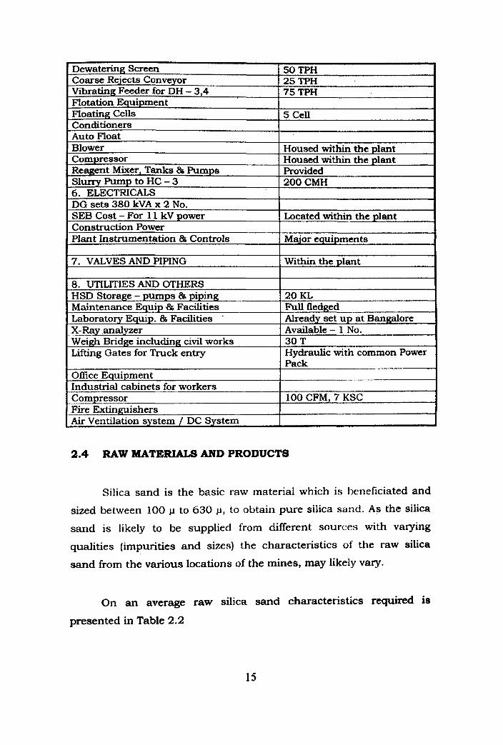
2.4 RAW MATE- AND PRODUCTS
Silica sand is the basic raw material which is beneficiated and
sized between 100 p to 630 p, to obtain pure silica sand. A s the silica
sand is likely to be supplied from different sources with varying
qualities (impurities and sizes) the characteristics of the raw silica
sand from the various locations of the mines, may likely vary.
.
Dewatering Screen Coarse Rejects Conveyor Vibrating Feeder for DH - 3,4 Flotation Equipment Floating Cells Conditioners - Auto Float Blower Compressor Reagent Mixer, Tanks % Pumps Slurry Pump to HC - 3 6. ELECTRICALS DG sets 380 kVA x 2 No. SEB Cost - For 1 1 kV power Construction Power Plant Instrumentation 86 Controls
7. VALVES AND PIPING
8. UTILITlES AND OTHERS HSD Storage - pumps & piping Maintenance Equip B Facilities Laboratory Equip. 86 Facilities . X-Ray analyzer Weigh Bridge including civil works Lifting Gates for Truck entry
Office Equipment Industrial cabinets for workers Compressor Fire Extinguishers Air Ventilation system / DC System
On an average raw silica sand characteristics required is
presented in Table 2.2
2
50 TPH 25 TPH 75 TPH
5 Cell
Housed within the plant Housed within the plant Provided 200 CMH
Located within the plant
Major equipment8
Within the plant
20 KL Full fledged Already set up at Bangalore Available - 1 No. 30 T Hydraulic with common Power Pack
100 CFM, 7 KSC
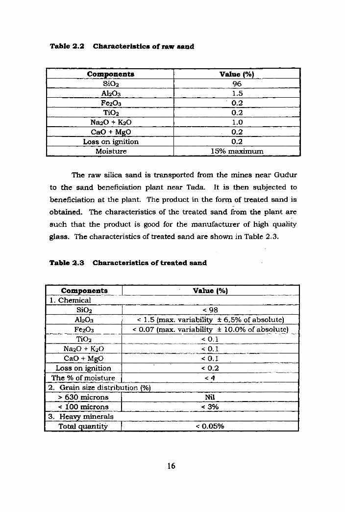
Table 2.2 Characterhtics of raw sand
The raw silica sand is transported from the mines near Gudur
SiOz A h 0 3 Fez03 Ti02
NazO + K2O CaO + MgO
Loss on ignition Moisture
i
to the sand beneficiation plant near Tada. It is then subjected to
96 1.5 0.2 0.2 1 .o 0.2 0.2
15% maximurn
beneficiation at the plant. The product in the form of treated sand is
obtained. The characteristics of the treated sand fmm the plant are
such that the product is good for the manufacturer of high quality
glass. The characteristics of treated sand are shown in Table 2.3.
Table 2.3 Characteristics of treated sand
Components I Value (YO) 1. Chemical
SiO2 A1203 Fez03 Ti02
NazO + K2O CaO + MgO
< 98 < 1.5 (max. variability * 6.5% of absolute)
< 0.07 (wax. variability f 10.0% of absolute) < 0.1 < 0.1 < 0.1 < 0.2
The % of moisture < 4 2. Grain size distribution (%)
> 630 microns < 100 microns
Nil < 3%
3. Heavy minerals Total quantity < 0.05%
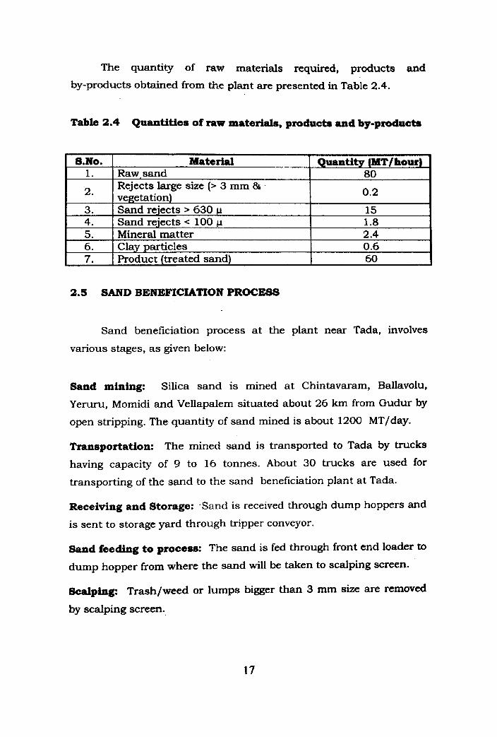
The quantity of raw materials required, products and
by-products obtained from the plant are presented in Table 2.4.
Table 2.4 Quantities of raw materials, products and by-products
2.5 SAND BENEFICIATION PROCESS
&No. 1.
2.
3. 4. 5. 6. 7.
Sand beneficiation process at the plant near Tada, involves
various stages, as given below:
Sand mining: Silica sand is mined at Chintavaram, Ballavolu,
Yeruru, Momidi and Vellapalem situated about 26 km from Gudur by
open stripping. The quantity of sand mined is about 1200 MT/day.
Material Raw,sand Rejects large size (> 3 mm 86 vegetation) Sand rejects > 630 p Sand rejects < 100 p Mineral matter Clay particles Product (treated sand)
Transportation: The mined sand is transported to Tada by trucks
having capacity of 9 to 16 tonnes. About 30 trucks are used for
transporting of the sand to the sand beneficiation plant at Tada.
Quantity (MT/ hour) 80
0.2
15 1.8 2.4 0.6 60
Receiving and Storage: .Sand is received through dump hoppers and
is sent to storage yard through tripper conveyor.
Sand feeding to process: The sand is fed through front end loader to
dump hopper from where the sand will be taken to scalping screen.
Scalping: Trash/weed or lumps bigger than 3 mm size are removed
by scalping screen.

Controlled silos: Screened sand is fed to control silos for feeding
uniformly at a rate of 75 to 80 tonnes/hour to sand beneficiation
plant. Two silos of 200 tonnes each are provided. This storage of
400 tonnes, will cater for nearly 5 hours of plant operation.
Sand Benefichation: The sand beneficiation process mainly
consists of
i) Over size removal
ii) Attrition of washing
iii) Heavy mineral separation and
iv) Dewatering and quality check
Over she removal: For the purpose of removing over size, unisizer is
used which works on the principle of hindered settlement. Water jets
acting from below, whose velocity can be adjusted, is used to separate
the sand into two fractions. The fraction greater than 630 j . ~ will settle
in the unisizer and discharged from below and the undersize less than
630 1 will overflow. This is achieved by setting the upward water
current in the controller of the unisizer. The under flow from the
unisizer having particle size greater than 630 p will be dewatered in a
dewatering screen and stored on a open pad for ,natural drying. The
overflow containing less than 630 p sand particles is fed into a vat and
pumped to a hydrocyclone for dewatering.
Attrition and washing: The sand slurry from the underflow of the
hydrocyclcone is fed into an Attritor wherein the clay adhering to the
sand particles will be separated. The attrited sand is pumped to a
hydrocyclone for the removal of clay and fines less than 100 y size.
Heavy mineral separation: The underflow of the hydrocyclone is fed
into the distribution box of the Rougher Spirals for removal of heavy
minerals. This works on the principle of density separation. Heavy
minerals having a specific gravity of greater than 2.6 will get separated
from sand having a specific gravity of 2.6. The good material is
collected in a vat and this slurry is again fed into Cleaner Spirals ibr
further separation of heavy minerals.
Dewatering: The good product from the spiral is fed into a vat, water
is added in the required quantity, and pumped through a slurry pump
to a hydrocyclone. Here the level of moisture is reduced to 25%. The
underflow from hydrocyclone is further dewatered in a Vibrating
Dewatering Screen down to 15% moisture.
Natural drying and storage of products. The treated sand coming
out of the processed plant at 60 tonnes/hour is dewatered using
dewatering screen to reduce moisture to less than 15% and is
conveyed and stored in a product storage shed.
Treated sand handling: The dried sand after inspection and
clearance is loaded on to trucks for dispatch for float plant at
Sriperambudur .
The schematic manufacturing process flow diagram is presented
in Fig. 2.4.
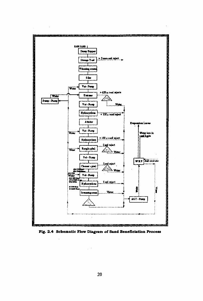
Fig. 2.4 Schematic Flow Diagram of Sand Beneficiation Process
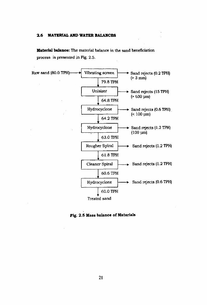
2.6 MATrCRUL AND WATER BALANCES
Material balance: The material balance in the sand beneficiation
process is presented in Fig. 2.5.
Raw sand (80.0 TPH) Sand rejects (0.2 TPH) (> 3 mm)
uni-b Sand rejects (15 TPH) (> 630 pm)
Hydrocyclone ---+ Sand rejects (0.6 TPH) (< 100 pm)
Hydrocyclone ----+ Sand rejects (1.2 TPH) (100 pm) 1 63.0 TPH
Rougher Spiral Sand rejects (1.2 TPH)
I Cleaner Spiral Sand rejects (1.2 TPH)
Sand rejects (0.6 TPH)
Treated sand
Fig. 2.5 Mass balance of Materials
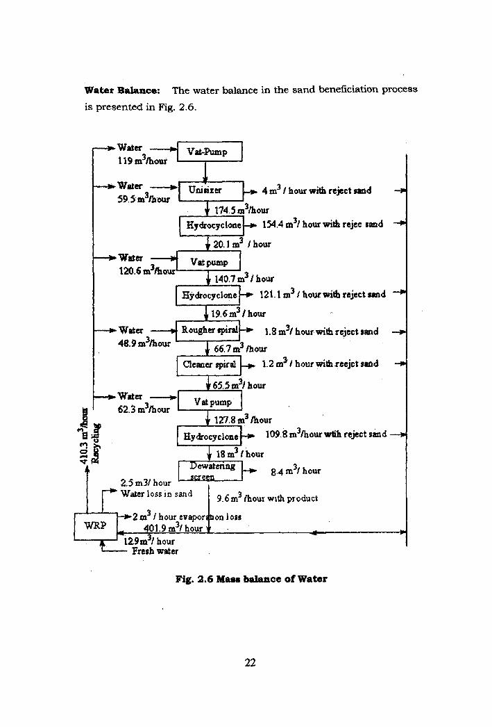
Water Balance: The water balance in the sand beneficiation process
is presented in Fig. 2.6.
4 -1 ~nisizcr 4 d , hour aih reject rand -I 59.5 m3bow I
m3/ hour with rcjcc sand +
120.6 m3hour 140.7 m3 I how
Hydrocyclone 121.1 m3 I hour with reject rand
m31 hour with reject sand -4
! hour with reejct rand -r
127.8 m3 hour - 1 0 9 3 m 3 a w
*.~m31h,r 2.5 m31 hour
reject sand
k 2 m3 ! hour cvaporrtron loas W 401.9m3/hourw . -.. 4
'E *12.9 rn3/ hour Fresh water
Fig. 2.6 Mass balance of Water
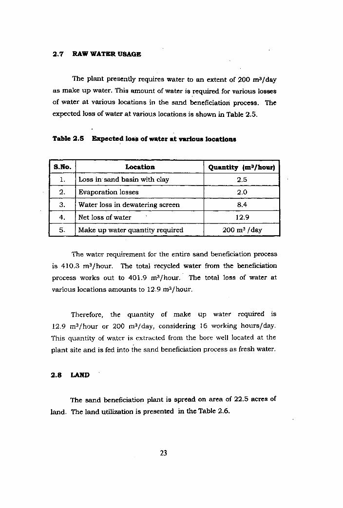
2.7 RAW WATER USAGE
The plant presently requires water to an extent of 200 m3/day
as make u p water. This amount of water is required for various losses
of water a t various locations in the sand beneficiation process. The expected loss of water at various locations is shown in Table 2.5.
Table 2.5 Expected loss of water at various location8
The water requirement for the entire sand beneficiation process
is 410.3 m3/hour. The total recycled water from the beneficiation
process works out to 401.9 m3/hour. The total loss of water at
various locations amounts to 12.9 m3/ hour.
. S.No.
1.
2.
3.
4.
5.
Therefore, the quantity of make up water required is
12.9 m3/hour or 200 m3/day, considering 16 working hours/day.
This quantity of water is extracted from the bore well located at the
plant site and is fed into the sand beneficiation process as fresh water.
2.8 LAND
Location
Loss in sand basin with clay
Evaporation losses
Water loss in dewatering screen
Net loss of water .
Make up water quantity required
The sand beneficiation plant is spread on area of 22.5 acres of
land. The land utilization is presented in the Table 2.6.
?
Quantity (m3fhour)
2.5
2.0
8.4
12.9
200 m3 /day
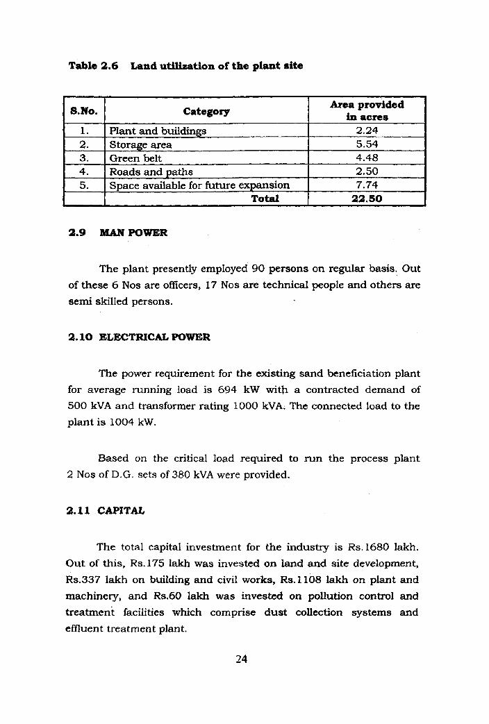
Table 2.6 Land utilization of the plant site
The plant presently employed 90 persons on regular basis. Out
of these 6 Nos are officers, 17 Nos are technical people and others are semi skilled persons.
2.10 ELECTRICAL POWER
Area provided In acres
2.24 5.54 4.48 2.50 7.74 22.50
&No.
1. 2. 3. 4. 5.
C
The power requirement for the existing sand beneficiation plant
for average running load is 694 kW with a contracted demand of
500 kVA and transformer rating 1000 kVA. The connected load to the
plant is 1004 kW.
Category
Plant and buildings Storage area Green belt Roads and paths Space available for future expansion
Total
Based on the critical load required to run the process plant
2 Nos of D.G. sets of 380 kVA were provided.
2.11 CAPITAL
The total capital investment for the industry is Rs. 1680 lakh.
Out of this, Rs.175 lakh was invested on land and site development,
Rs.337 lakh on building and civil works, Rs.1108 lakh on plant and
machinery, and Rs.60 lakh was invested on pollution control and
treatment facilities which comprise dust collection systems and
effluent treatment plant.