Bending Stress - University of Southern Californiasubhayad/bending.pdf · 2018-02-25 · Bending...
14
Bending Stress Sign convention The positive shear force and bending moments are as shown in the figure. Figure 40: Sign convention followed. Centroid of an area If the area can be divided into n parts then the distance ¯ Y of the centroid from a point can be calculated using ¯ Y =  n i=1 A i ¯ y i  n i=1 A i where A i = area of the ith part, ¯ y i = distance of the centroid of the ith part from that point. Second moment of area, or moment of inertia of area, or area moment of inertia, or second area moment For a rectangular section, moments of inertia of the cross-sectional area about axes x and y are Figure 41: A rectangular section. I x = 1 12 bh 3 I y = 1 12 hb 3 Parallel axis theorem This theorem is useful for calculating the moment of inertia about an axis parallel to either x or y. For example, we can use this theorem to calculate I x 0 .
Transcript of Bending Stress - University of Southern Californiasubhayad/bending.pdf · 2018-02-25 · Bending...

Bending Stress
Sign convention
The positive shear force and bending moments are as shown in thefigure.
Scanned by CamScanner
Figure 40: Sign convention followed.Centroid of an area
If the area can be divided into n parts then the distance Y of thecentroid from a point can be calculated using
Y =Ân
i=1 Aiyi
Âni=1 Ai
where Ai = area of the ith part, yi = distance of the centroid of the ithpart from that point.
Second moment of area, or moment of inertia of area, or areamoment of inertia, or second area moment
For a rectangular section, moments of inertia of the cross-sectionalarea about axes x and y are
Scanned by CamScanner
Figure 41: A rectangular section.
Ix =1
12bh3
Iy =1
12hb3
Parallel axis theorem
This theorem is useful for calculating the moment of inertia about anaxis parallel to either x or y. For example, we can use this theorem tocalculate Ix0 .

Ix0 = Ix + Ad2
Bending stress
Bending stress at any point in the cross-section is
s = �MyI
where y is the perpendicular distance to the point from the centroidalaxis and it is assumed +ve above the axis and -ve below the axis. Thiswill result in +ve sign for bending tensile (T) stress and -ve sign forbending compressive (C) stress.
Largest normal stress
Largest normal stress
sm =|M|max · c
I=
|M|maxS
where S = section modulus for the beam.For a rectangular section, the moment of inertia of the cross-
sectional area I = 112 bh3, c = h/2, and S = I/c = 1
6 bh2.We require sm sall (allowable stress)This gives
Smin =|M|max
sall
The radius of curvature
The radius of curvature r in the bending of a beam can be estimatedusing
1r=
MEI
Problem 1.
Draw the bending moment and shear force diagram of the followingbeam.
Subhayan De, USC
Scanned by CamScanner
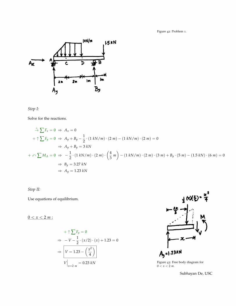
Figure 42: Problem 1.
Step I:
Solve for the reactions.
+! Â Fx = 0 ) Ax = 0
+ " Â Fy = 0 ) Ay + By �12· (1 kN/m) · (2 m)� (1 kN/m) · (2 m) = 0
) Ay + By = 3 kN
+ x  MA = 0 ) � 12· (1 kN/m) · (2 m) ·
✓43
m◆� (1 kN/m) · (2 m) · (3 m) + By · (5 m)� (1.5 kN) · (6 m) = 0
) By = 3.27 kN
) Ay = 1.23 kN
Step II:
Use equations of equilibrium.
0 < x < 2 m :
Scanned by CamScanner
Figure 43: Free body diagram for0 < x < 2 m.
+ " Â Fy = 0
) � V � 12· (x/2) · (x) + 1.23 = 0
) V = 1.23 �✓
x2
4
◆
V���x=2 m
= 0.23 kN
Subhayan De, USC
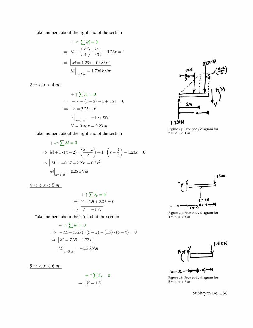
Take moment about the right end of the section
+ x  M = 0
) M +
✓x2
4
◆·⇣ x
3
⌘� 1.23x = 0
) M = 1.23x � 0.083x3
M���x=2 m
= 1.796 kNm
2 m < x < 4 m :
Scanned by CamScanner
Figure 44: Free body diagram for2 m < x < 4 m.
+ " Â Fy = 0
) � V � (x � 2)� 1 + 1.23 = 0
) V = 2.23 � x
V���x=4 m
= �1.77 kN
V = 0 at x = 2.23 m
Take moment about the right end of the section
+ x  M = 0
) M + 1 · (x � 2) ·✓
x � 22
◆+ 1 ·
✓x � 4
3
◆� 1.23x = 0
) M = �0.67 + 2.23x � 0.5x2
M���x=4 m
= 0.25 kNm
4 m < x < 5 m :
Scanned by CamScanner
Figure 45: Free body diagram for4 m < x < 5 m.
+ " Â Fy = 0
) V � 1.5 + 3.27 = 0
) V = �1.77
Take moment about the left end of the section
+ x  M = 0
) � M + (3.27) · (5 � x)� (1.5) · (6 � x) = 0
) M = 7.35 � 1.77x
M���x=5 m
= �1.5 kNm
Scanned by CamScanner
Figure 46: Free body diagram for5 m < x < 6 m.
5 m < x < 6 m :
+ " Â Fy = 0
) V = 1.5
Subhayan De, USC

Take moment about the left end of the section
+ x  M = 0
) � M � (1.5) · (6 � x) = 0
) M = 1.5x � 9
Note: V =dMdx
The BMD and SFD are drawn next.
Scanned by CamScanner
Figure 47: Bending moment and shearforce diagrams.
Subhayan De, USC

Note: Maximum bending moment occurs at x⇤ where
dMdx
���x=x⇤
= 0
V = 0
2.23 � x⇤ = 0
x⇤ = 2.23 m
Problem 2.
(a) Draw the bending moment and shear force diagram of the follow-ing beam.
Scanned by CamScanner
�
�
Figure 48: Problem 2.
Step I:
Solve for the support reactions.
+! Â Fx = 0 ) Ax = 0
+ " Â Fy = 0 ) Ay + By = 4 kN
+ x  MA = 0 ) � (4 kN) · (1 m) + 2.8 kNm + By · (3 m) = 0
) By = 0.4 kN
) Ay = 3.6 kN
Step II:
Use equations of equilibrium.
Subhayan De, USC

0 < x < 1 m :
Scanned by CamScanner
�
�
Figure 49: Free body diagram for0 < x < 1 m.
+ " Â Fy = 0
) V = 3.6
Take moment about the right end of the section
+ x  M = 0
) M � (3.6) · x = 0
) M = 3.6x
M���x=1 m�Dx
= 3.6 kNm
1 m < x < 2 m :
Scanned by CamScanner
�
�
Figure 50: Free body diagram for1 m < x < 2 m.
+ " Â Fy = 0
) � V � 4 + 3.6 = 0
) V = �0.4
Take moment about the right end of the section
+ x  M = 0
) M + 4 · (x � 1)� (3.6) · x = 0
) M = 4 � 0.4x
M���x=1 m+Dx
= 3.6 kNm
M���x=2 m�Dx
= 3.2 kNm
2 m < x < 3 m :
Scanned by CamScanner
�
�
Figure 51: Free body diagram for2 m < x < 3 m.
+ " Â Fy = 0
) V = �0.4
Take moment about the left end of teh section
+ x  M = 0
) M = 0.4(3 � x)
M���x=2 m+Dx
= 0.4 kNm
(b) Check the required section for this beam with sall = 25 MPa.Here, |M|max = 3.6 kNm.
Smin =|M|max
sall=
3.6 ⇥ 103 Nm25 ⇥ 106 N/m2
= 1.44 ⇥ 10�4m3
= 144 ⇥ 103 mm3
Subhayan De, USC
Scanned by CamScanner
�
�
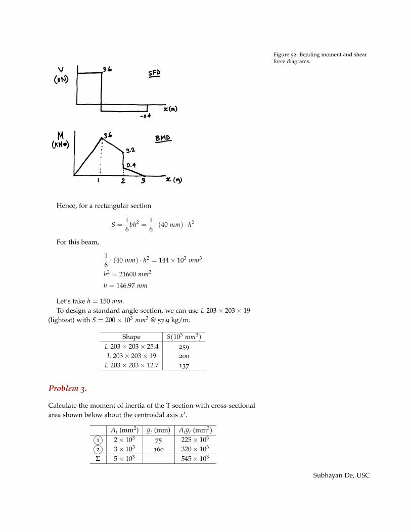
Figure 52: Bending moment and shearforce diagrams.
Hence, for a rectangular section
S =16
bh2 =16· (40 mm) · h2
For this beam,
16· (40 mm) · h2 = 144 ⇥ 103 mm3
h2 = 21600 mm2
h = 146.97 mm
Let’s take h = 150 mm.To design a standard angle section, we can use L 203 ⇥ 203 ⇥ 19
(lightest) with S = 200 ⇥ 103 mm3 @ 57.9 kg/m.
Shape S(103 mm3)
L 203 ⇥ 203 ⇥ 25.4 259
L 203 ⇥ 203 ⇥ 19 200
L 203 ⇥ 203 ⇥ 12.7 137
Problem 3.
Calculate the moment of inertia of the T section with cross-sectionalarea shown below about the centroidal axis x0.
Ai (mm2) yi (mm) Aiyi (mm3)1 2 ⇥ 103
75 225 ⇥ 103
2 3 ⇥ 103160 320 ⇥ 103
S 5 ⇥ 103 545 ⇥ 103
Subhayan De, USC
Scanned by CamScanner
" 1 "
-
9 9
'"
�
Ą 9
@ @ � � ��
2 1 4
2 9 ( 9ã 2 9
� = 0 9
ļ "
� 9
. " .
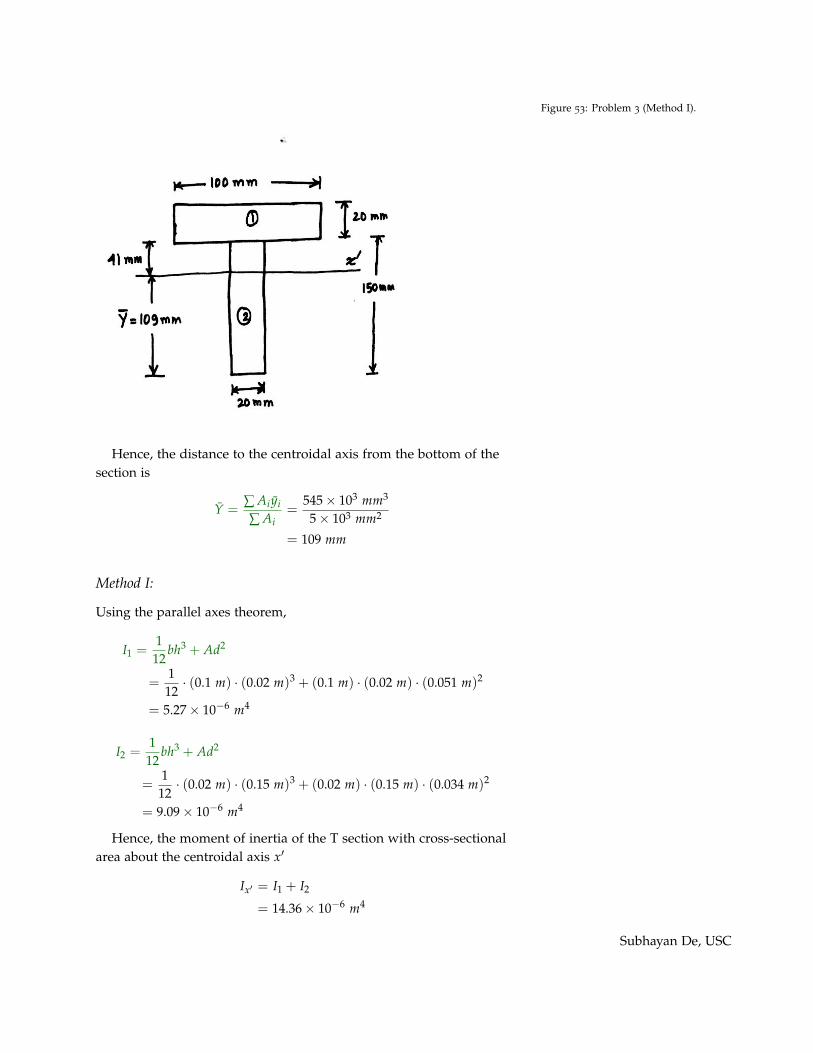
Figure 53: Problem 3 (Method I).
Hence, the distance to the centroidal axis from the bottom of thesection is
Y =Â Aiyi
 Ai=
545 ⇥ 103 mm3
5 ⇥ 103 mm2
= 109 mm
Method I:
Using the parallel axes theorem,
I1 =112
bh3 + Ad2
=1
12· (0.1 m) · (0.02 m)3 + (0.1 m) · (0.02 m) · (0.051 m)2
= 5.27 ⇥ 10�6 m4
I2 =1
12bh3 + Ad2
=112
· (0.02 m) · (0.15 m)3 + (0.02 m) · (0.15 m) · (0.034 m)2
= 9.09 ⇥ 10�6 m4
Hence, the moment of inertia of the T section with cross-sectionalarea about the centroidal axis x0
Ix0 = I1 + I2
= 14.36 ⇥ 10�6 m4
Subhayan De, USC
Method II:
Scanned by CamScanner
" 1 "
-
9 9
'"
�
Ą 9
@ @ � � ��
2 1 4
2 9 ( 9ã 2 9
� = 0 9
ļ "
� 9
. " .
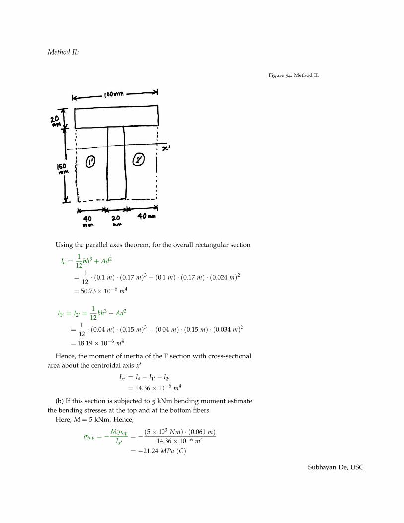
Figure 54: Method II.
Using the parallel axes theorem, for the overall rectangular section
Io =112
bh3 + Ad2
=1
12· (0.1 m) · (0.17 m)3 + (0.1 m) · (0.17 m) · (0.024 m)2
= 50.73 ⇥ 10�6 m4
I10 = I20 =112
bh3 + Ad2
=112
· (0.04 m) · (0.15 m)3 + (0.04 m) · (0.15 m) · (0.034 m)2
= 18.19 ⇥ 10�6 m4
Hence, the moment of inertia of the T section with cross-sectionalarea about the centroidal axis x0
Ix0 = Io � I10 � I20
= 14.36 ⇥ 10�6 m4
(b) If this section is subjected to 5 kNm bending moment estimatethe bending stresses at the top and at the bottom fibers.
Here, M = 5 kNm. Hence,
stop = �Mytop
Ix0= � (5 ⇥ 103 Nm) · (0.061 m)
14.36 ⇥ 10�6 m4
= �21.24 MPa (C)
Subhayan De, USC
sbot = �MybotIx0
= � (5 ⇥ 103 Nm) · (�0.109 m)
14.36 ⇥ 10�6 m4
= 37.95 MPa (T)
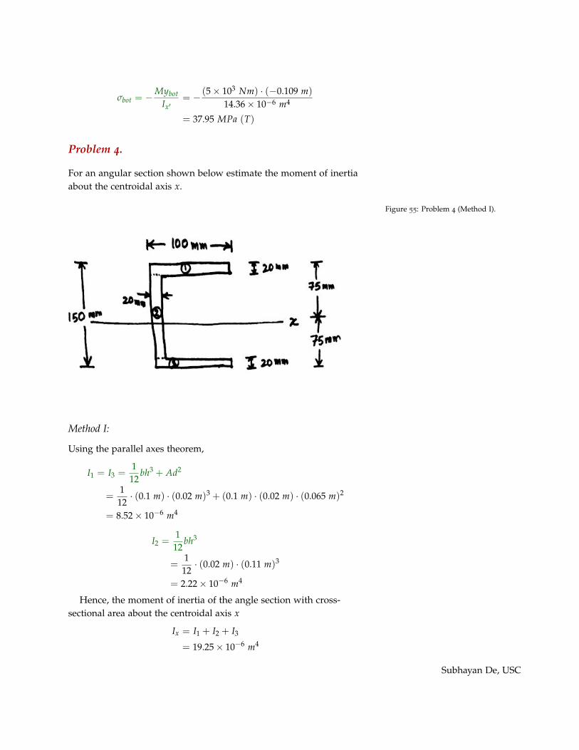
Problem 4.
For an angular section shown below estimate the moment of inertiaabout the centroidal axis x.
Scanned by CamScanner
ļ
Figure 55: Problem 4 (Method I).
Method I:
Using the parallel axes theorem,
I1 = I3 =112
bh3 + Ad2
=1
12· (0.1 m) · (0.02 m)3 + (0.1 m) · (0.02 m) · (0.065 m)2
= 8.52 ⇥ 10�6 m4
I2 =112
bh3
=112
· (0.02 m) · (0.11 m)3
= 2.22 ⇥ 10�6 m4
Hence, the moment of inertia of the angle section with cross-sectional area about the centroidal axis x
Ix = I1 + I2 + I3
= 19.25 ⇥ 10�6 m4
Subhayan De, USC

Method II:
Scanned by CamScanner
ļFigure 56: Method II.
For the overall rectangular section
Io =1
12bh3
=1
12· (0.1 m) · (0.15 m)3
= 28.13 ⇥ 10�6 m4
I10 =112
bh3
=112
· (0.08 m) · (0.11 m)3
= 8.87 ⇥ 10�6 m4
Hence, the moment of inertia of the angle section with cross-sectional area about the centroidal axis x
Ix = Io � I10
= 19.25 ⇥ 10�6 m4
Problem 5.
Calculate (a) maximum bending stress in the section, (b) bendingstress at point B in the section, and (c) the radius of curvature.
Using the parallel axes theorem,
I1 = I3 =1
12bh3 + Ad2
=1
12· (0.25 m) · (0.02 m)3 + (0.25 m) · (0.02 m) · (0.16 m)2
= 128.17 ⇥ 10�6 m4
I2 =1
12bh3
=1
12· (0.02 m) · (0.3 m)3
= 45 ⇥ 10�6 m4
Hence, moment of inertia of the cross-sectional area about thecentroidal axis x
Ix = I1 + I2 + I3
= 301.33 ⇥ 10�6 m4
(a) Maximum bending stress
sm =|M|max · c
Ix= � (45 ⇥ 103 Nm) · (0.17 m)
301.33 ⇥ 10�6 m4
= 25.4 MPa
Subhayan De, USC

Scanned by CamScanner
" 1 "
-
9 9
'"
�
Ą 9
@ @ � � ��
2 1 4
2 9 ( 9ã 2 9
� = 0 9
ļ "
� 9
. " .
Figure 57: Problem 5.
(b) Bending stress at B
sB = �MyBIx
= � (45 ⇥ 103 Nm) · (�0.15 m)
301.33 ⇥ 10�6 m4
= 22.4 MPa
(c)
1r=
MEIx
=(45 ⇥ 103 Nm)
(200 ⇥ 109 Pa) · (301.33 ⇥ 10�6 m4)
= 7.47 ⇥ 10�4 m�1
Hence, the radius of curvature
r = 1339 m
(d) If a rolled steel section W 200 ⇥ 86 is used then we have
Ix = 94.9⇥ 106 m4 = 94.9⇥ 10�6 m4, c = 0.111 m, yB = �(0.111� 0.0206) m = �0.0904 m
Maximum bending stress
sm =|M|max · c
Ix= � (45 ⇥ 103 Nm) · (0.111 m)
94.9 ⇥ 10�6 m4
= �52.63 MPa (C)
Subhayan De, USC

Bending stress at B
sB = �MyBIx
= � (45 ⇥ 103 Nm) · (�0.0904 m)
94.9 ⇥ 10�6 m4
= 42.87 MPa (T)
1r=
MEIx
= 2.37 ⇥ 10�3 m�1
The radius of curvaturer = 421.8 m
Subhayan De, USC